

Page 1

9087A – 198th Street, Langley, BC Canada V1M 3B1 Telephone (604) 888-0110
TSC 900
TRANSFER SWITCH CONTROLLER
INSTALLATION, OPERATING &
SERVICE MANUAL
Part ID PM151 REV 5 16/04/19
Page 2

TSC 900 TRANSFER SWITCH CONTROLLER
PM 151 REV 5 16/04/19 Thomson Power Systems
Page 3

TSC 900 TRANSFER SWITCH CONTROLLER
PM 151 REV 5 16/04/19 Thomson Power Systems
TABLE OF CONTENTS
1. INTRODUCTION 1
1.1. PRODUCT REVISION HISTORY 1
1.2. GENERAL DESCRIPTION 2
2. INSTALLATION 2
2.1. GENERAL INFORMATION 3
2.2. NOTES TO INSTALLER 3
2.3. TSC 900 GHC MOUNTING 4
2.4. AC VOLTAGE SENSING INPUT 5
2.5. AC CURRENT SENSING INPUT 7
2.6. AC CONTROL POWER INPUT 8
2.7. AUXILIARY DC CONTROL POWER INPUT 8
2.8. PROGRAMMABLE INPUTS 8
2.9. OUTPUTS 8
2.10. EXTERNAL ATS CONTROL WIRING 8
2.11. REMOTE START CONTACT FIELD WIRING 9
2.12. COMMUNICATION CABLE INSTALLATION 10
2.13. DIELECTRIC TESTING 10
3. DESCRIPTION 11
3.1. GRAPHICAL HMI CONTROLLER (GHC) DISPLAY HARDWARE 12
3.2. SWITCH CONTROL UNIT (SCU) HARDWARE 13
3.3. ATS OPERATION MODE DESCRIPTIONS 15
3.4. AUTOMATIC SEQUENCE OF OPERATION 17
3.4.1. OPEN TRANSITION TRANSFER 17
3.4.2. CLOSED TRANSITION TRANSFER 17
3.4.3. DUAL SOURCE ATS 19
3.4.4. AUTOMATIC LOAD SHED OPERATION 22
3.4.5. TEST MODE 23
3.4.6. ABNORMAL SEQUENCE OF OPERATION 24
Page 4

TSC 900 TRANSFER SWITCH CONTROLLER
PM 151 REV 5 16/04/19 Thomson Power Systems
3.5. GHC DISPLAY MAIN MENU PAGE DESCRIPTIONS 25
3.5.1. HOME PAGE 26
3.5.2. UTILITY METERING PAGE 27
3.5.3. GENERATOR METERING PAGE 27
3.5.4. LOAD METERING PAGE 28
3.5.5. ALARMS PAGE 28
3.5.6. ALARMS LOG PAGE 29
3.5.7. EVENTS LOG PAGE 31
3.5.8. SYNC PAGE 32
3.5.9. SCHEDULER PAGE 33
3.5.10. SETTINGS PAGE 33
3.5.11. SYSTEM PAGE 34
3.6. GHC DISPLAY SYSTEM SUBMENU PAGE DESCRIPTIONS 35
3.6.1. IMPORT/EXPORT DATA 35
3.6.2. DATE / TIME SETUP 35
3.6.3. MANAGE USERS 36
3.6.4. SYSTEM INFORMATION 36
3.6.5. INPUT MAPPING 37
3.6.6. OUTPUT MAPPING 37
3.6.7. LOGS 38
3.6.8. COMMUNICATION STATUS 38
3.6.9. MIMIC BUS CUSTOMIZATION 39
3.6.10. FIRMWARE UPDATES 39
3.6.11. GHC HEALTH 39
4. OPERATING INSTRUCTIONS 40
4.1. GHC SCREEN PAGE NAVIGATION 40
4.2. HELP INFORMATION 40
4.3. ON LOAD TEST INSTRUCTIONS (UTILITY POWER FAIL SIMULATION) 41
4.4. OFF LOAD TEST INSTRUCTIONS (GENERATOR NO LOAD TEST) 42
4.5. TIMED TEST INSTRUCTION 43
4.6. OPEN/CLOSED TRANSITION TRANSFER OPERATION 45
4.6.1. OPEN TRANSITION IN-SYNC TRANSFER OPERATION (MODEL X) 46
4.6.2. CLOSED TRANSITION OPERATION (FAST TRANSFER MODEL 3) 46
4.6.3. CLOSED TRANSITION OPERATION (SOFT-LOAD TRANSFER MODEL 4) 47
4.7. DUAL SOURCE ATS OPERATION 50
4.7.1. DUAL SOURCE - CHANGING PREFERRED UNITS (GHC CONTROL) 51
4.8. TRANSFER FAIL ALARM RESET 52
Page 5

TSC 900 TRANSFER SWITCH CONTROLLER
PM 151 REV 5 16/04/19 Thomson Power Systems
4.9. TIMER BYPASS 52
4.10. MANUAL UTILITY RETRANSFER CONTROL 53
4.11. SERVICE DISCONNECT MODE 53
4.12. PHASE UNBALANCE PROTECTION ALARM RESET 54
4.13. TRANSFER HALTED ALARM RESET 55
4.14. ABNORMAL SOURCE ALERT 56
5. PROGRAMMING INSTRUCTIONS 57
5.1. PASSWORD SECURITY DESCRIPTION (USERS ADMIN) 57
5.2. USER LOGIN PROCEDURE 58
5.3. ADMINISTRATOR PASSWORD MANAGEMENT PROCEDURE 59
5.4. SYSTEM TIME/DATE ADJUSTMENT 60
5.5. VOLTAGE CHANGE PROCEDURE 61
5.6. REMOTE COMMUNICATION SETUP 63
5.7. EXERCISE TIMER SETUP 63
5.7.1. ADDING NEW EXERCISE SCHEDULE EVENT 63
5.7.2. EDITING EXISTING EXERCISE SCHEDULE EVENT 64
5.8. PROGRAMMABLE DIGITAL INPUT MAPPING 65
5.8.1. TS 870 STANDARD/SERVICE ENTRANCE INPUT DEFAULTS: 65
5.8.2. TS 870 DUAL SOURCE INPUT DEFAULTS: 65
5.8.3. TS 880 (ICS) STANDARD/SERVICE ENTRANCE INPUT DEFAULTS: 66
5.8.4. TS 880 (ICS) CLOSED TRANSITION INPUT DEFAULTS: 66
5.8.5. PROGRAMMABLE INPUT FUNCTION LIST 67
5.8.6. PROGRAMMABLE INPUT FUNCTION MAPPING 69
5.8.7. PROGRAMMABLE INPUT USER DEFINED CUSTOM NAME MAPPING 70
5.9. PROGRAMMABLE OUTPUT MAPPING 72
5.9.1. TS 870 STANDARD/SERVICE ENTRANCE OUTPUT DEFAULTS: 72
5.9.2. TS 870 DUAL SOURCE OUTPUT DEFAULTS: 72
5.9.3. TS 880 (ICS) STANDARD/SERVICE ENTRANCE OUTPUT DEFAULTS: 72
5.9.4. TS 880 (ICS) CLOSED TRANSITION OUTPUT DEFAULTS: 72
5.9.5. PROGRAMMABLE OUTPUT FUNCTION LIST 73
5.9.6. PROGRAMMABLE OUTPUT FUNCTION MAPPING 76
5.10. SYSTEM SETTINGS 77
5.10.1. SYSTEM PHASES 78
5.10.2. SYSTEM VOLTAGE 78
5.10.3. SYSTEM FREQUENCY 78
Page 6

TSC 900 TRANSFER SWITCH CONTROLLER
PM 151 REV 5 16/04/19 Thomson Power Systems
5.10.4. PHASE ROTATION REVERSED 78
5.10.5. RATED GENERATOR POWER 78
5.10.6. CT RATIO (CURRENT TRANSFORMER) 78
5.10.7. PT RATIO (POTENTIAL TRANSFORMER) 78
5.10.8. LOAD NAME 79
5.10.9. SOURCE 1 (UTILITY) NAME 79
5.10.10. SOURCE 2 (GEN) NAME 79
5.10.11. APPLICATION MODEL 79
5.10.12. SWITCH OPERATION 79
5.10.13. SWITCH MODEL 79
5.11. OPTION SETTINGS 79
5.11.1. SRC 2 (GEN) COMMIT TO TRANSFER 79
5.11.2. ENABLE LOAD SHED ON UNDER FREQUENCY 80
5.11.3. ENABLE LOAD SHED ON OVER POWER 80
5.11.4. HALT OPERATION ON PHASE REVERSAL 80
5.11.5. MANUAL SRC 1 (UTILITY) RETRANSFER CONTROL 80
5.11.6. FORCE TRANSFER 81
5.11.7. GHC SLEEP MODE TIMEOUT 81
5.11.8. LOAD POWER METERING 81
5.11.9. MODBUS RTU 81
5.11.10. MODBUS TCP/IP 82
5.11.11. ENABLE SECURITY BYPASS 82
5.11.12. ENABLE NEUTRAL DELAY BYPASS 82
5.11.13. ENABLE TRANSFERS TO SRC 1 (UTILITY) 82
5.11.14. ENABLE TRANSFERS TO SRC 2 (GENERATOR) 83
5.11.15. ENABLE FAIL TO AUTO SYNC ALARM 83
5.11.16. ENABLE HALT TRANSFER ON FAIL TO EXTERNAL SYNC CHECK 83
5.11.17. ENABLE CLOSED TRANSITION TRANSFER (CTTS MODEL 3 & 4) 83
5.11.18. REVERT TO OPEN TRANSITION 84
5.11.19. ENABLE FAIL TO UNLOAD ALARM (CTTS MODEL 4) 84
5.11.20. ENABLE EXTENDED PARALLEL MODE (CTTS MODEL 4) 85
5.11.21. ENABLE SOFT-LOAD TRANSFER (CTTS MODEL 4) 85
5.11.22. ENABLE START OF MULTIPLE GENS WHEN RESUMING FROM STANDBY 85
5.11.23. PREFERRED SOURCE ALTERNATION INTERVAL 86
5.11.24. TRIP UTILITY (SRC 1) WHEN CLOSED TRANSITION INHIBIT ACTIVATED 86
5.11.25. CURRENT METERING 86
5.11.26. ENABLE OPEN TRANSITION IN-SYNC TRANSFER (ATS MODEL X) 86
5.12. DELAY SETTINGS 87
5.12.1. UTILITY (SRC 1) RETURN DELAY 87
5.12.2. GEN (SRC 2) COOL DOWN DELAY 87
5.12.3. GEN (SRC 2) START DELAY 87
Page 7

TSC 900 TRANSFER SWITCH CONTROLLER
PM 151 REV 5 16/04/19 Thomson Power Systems
5.12.4. GEN (SRC 2) WARM UP DELAY 87
5.12.5. TRANSFER NEUTRAL DELAY 88
5.12.6. TRANSFER PRE DELAY (LDC) 88
5.12.7. TRANSFER POST DELAY (LDC) 88
5.12.8. SRC 2 (GEN) GEN COMMIT TO TRANSFER DELAY 88
5.12.9. TRANSFER FAIL DELAY 88
5.12.10. TRANSFER MAX ERROR CONDITION DELAY 88
5.12.11. GEN (SRC 2) FAILED TO START DELAY 89
5.12.12. DISCONNECTION RESUME TIME 89
5.12.13. TRIP RETRY ON/OFF PULSE TIME (SRC1&2) 89
5.12.14. TRIP RETRY DURATION TIMER (SRC1&2) 89
5.12.15. CLOSE RETRY ON/OFF PULSE TIME (SRC1&2) 89
5.12.16. CLOSE RETRY DURATION TIMER (SRC1&2) 90
5.12.17. TIMER GUARD DELAY 90
5.12.18. FIND NEUTRAL DELAY 90
5.12.19. RETURN TO PREFERRED SOURCE DELAY 91
5.12.20. WAIT FOR PREFERRED SOURCE DELAY 91
5.12.21. TRANSFER FROM PREFERRED SOURCE DELAY 91
5.13. UTILITY/GEN SET POINTS (VOLTAGE/FREQUENCY) 91
5.13.1. UNDER VOLTAGE DELAY (DROPOUT) 92
5.13.2. UNDER VOLTAGE DROPOUT 92
5.13.3. UNDER VOLTAGE PICKUP 92
5.13.4. OVER VOLTAGE DELAY (PICKUP) 92
5.13.5. OVER VOLTAGE DROPOUT 92
5.13.6. OVER VOLTAGE PICKUP 92
5.13.7. PHASE UNBALANCED VOLTAGE LATCH 92
5.13.8. PHASE UNBALANCE DELAY (PICKUP) 93
5.13.9. PHASE UNBALANCE DROPOUT 93
5.13.10. PHASE UNBALANCE PICK UP 93
5.13.11. UNDER FREQUENCY DELAY (DROPOUT) 93
5.13.12. UNDER FREQUENCY DROPOUT 93
5.13.13. UNDER FREQUENCY PICKUP 94
5.13.14. OVER FREQUENCY DELAY (PICKUP) 94
5.13.15. OVER FREQUENCY DROPOUT 94
5.13.16. OVER FREQUENCY PICKUP 94
5.13.17. VOLTAGE SOURCE BLACKOUT DELAY (DROPOUT) 94
5.13.18. VOLTAGE SOURCE BLACKOUT DROPOUT 94
5.13.19. VOLTAGE SOURCE BLACKOUT PICKUP 94
5.13.20. VOLTAGE ROTATION REVERSAL DELAY (PICKUP) 95
5.13.21. VOLTAGE ROTATION REVERSAL DROP OUT 95
5.13.22. VOLTAGE ROTATION REVERSAL PICK UP 95
Page 8

TSC 900 TRANSFER SWITCH CONTROLLER
PM 151 REV 5 16/04/19 Thomson Power Systems
5.14. LOAD VOLTAGE SET POINTS 95
5.14.1. LOAD VOLTAGE BLACKOUT DELAY (DROPOUT) 95
5.14.2. LOAD VOLTAGE BLACKOUT DROPOUT 95
5.14.3. LOAD VOLTAGE BLACKOUT PICKUP 95
5.15. LOAD SHED FREQUENCY & POWER SET POINTS 96
5.15.1. LOAD SHED INITIATE DELAY 96
5.15.2. LOAD SHED UNSHED DELAY 96
5.15.3. LOAD SHED FREQUENCY DELAY (PICKUP) 97
5.15.4. LOAD SHED FREQUENCY PICK UP 97
5.15.5. LOAD SHED FREQUENCY DROP OUT 97
5.15.6. LOAD SHED POWER (kW) DELAY (PICKUP) 97
5.15.7. LOAD SHED POWER (kW) DROP OUT 97
5.15.8. LOAD SHED POWER (kW) PICK UP 97
5.16. IN-SYNC TRANSFER SET POINTS 97
5.16.1. IN-SYNC WAIT DELAY 97
5.16.2. EXTERNAL SYNC CHECK WAIT DELAY 98
5.16.3. FAIL TO UNLOAD TIMER (CTTS MODEL 4) 98
5.16.4. CLOSED TRANSITION MAX OVERLAP TIMER 98
5.16.5. SOURCE FREQUENCY DIFFERENTIAL HIGHER THRESHOLD 98
5.16.6. SOURCE FREQUENCY DIFFERENTIAL LOWER THRESHOLD 99
5.16.7. SOURCE VOLTAGE DIFFERENTIAL HIGHER THRESHOLD 99
5.16.8. SOURCE VOLTAGE DIFFERENTIAL LOWER THRESHOLD 99
5.16.9. TRANSFER SWITCH MECHANISM OPERATION TIME 99
6. FACTORY DEFAULT PROGRAMMING 100
7. TSC 900 TYPICAL CONNECTION DIAGRAM 104
8. TSC 900 WIRING PIN CONNECTIONS 105
9. TROUBLESHOOTING 106
10. REPLACEMENT PARTS 110
11. PRODUCT RETURN POLICY 111
12. NOTES 112
Page 9

TSC 900 TRANSFER SWITCH CONTROLLER
PM 151 REV 5 16/04/19 Thomson Power Systems
1
1. INTRODUCTION
1.1. PRODUCT REVISION HISTORY
The following information provides an historical summary of changes made to this product since
the original release.
SCU Firmware Version
621, 15/04/07
Original Release
867, 15/10/03
Add Closed Transition Transfer Capability, Misc.
Feature Enhancements & Bug Fixes
888, 15/10/28
Add Dual Source Capability, Misc. Feature
Enhancements & Bug Fixes
902, 15/11/18
Add Remote Load Dump Control (RLDC) feature
capability
GHC Firmware Version
1.0.0.0 15/04/07
Original Release
1.1.0.xxxxx 15/10/03
Add Closed Transition Transfer Capability, Misc.
Feature Enhancements & Bug Fixes
1.1.0.16017 15/10/30
Add Dual Source Capability, Misc. Feature
Enhancements & Bug Fixes
1.1.5805.19916 15/11/18
Add Remote Load Dump Control (RLDC) feature
capability
1.1.5952.22994 16/04/19
Update Alarm Tag Names, add GHC Firmware
Update, Misc. Feature Enhancements & Bug Fixes
Operating & Service Manual Version
Rev 0 15/04/07
Original release
Rev 1 15/10/08
Add Closed Transition Transfer Capability, Misc.
Feature Enhancements & Bug Fixes
Rev 2 15/11/11
Add Dual Source Capability, Misc. Feature
Enhancements & Bug Fixes
Rev 3 15/11/24
Add Remote Load Dump Control (RLDC) Feature
capability
Rev 4 16/01/15
Update Alarm Tag Names, add GHC Firmware
Update, Add TSC 900 Faceplate mounting
information
Rev 5 16/04/19
Miscellaneous minor manual revisions
Related Product Instruction Manuals
• TSC 900 ModbusTM Communication, PM152
• TS 870 Instruction Manual, PM062
• TS 870 Quick Start Manual, PM150
• TS 880 Instruction Manual, PM064
Contact Thomson Power Systems, to obtain these instruction manuals. A soft-copy of the most
current versions of these manuals are available at www.thomsonps.com.
Page 10

TSC 900 TRANSFER SWITCH CONTROLLER
PM 151 REV 5 16/04/19 Thomson Power Systems
2
1.2. GENERAL DESCRIPTION
The TSC 900 controller utilizes multiple 32-bit microprocessor-based design technology, which
provides high accuracy for all voltage sensing and timing functions. Digital Signal Processing
(DSP) technology is utilized for all voltage, frequency and current sensing. The TSC 900 is
factory configured to control all the operational functions and display features of the automatic
transfer switch. All features of the TSC 900 are fully programmable from the front panel color
graphical touchscreen display and are security password protected. The graphical touchscreen
display screen provides a user-friendly operator interface with many display options available.
2. INSTALLATION
CAUTION!!!
This equipment contains static-sensitive parts. Please observe the following
anti-static precautions at all times when handling this equipment. Failure to
observe these precautions may cause equipment failure and/or damage.
The following precautions must be observed:
• Discharge body static charge before handling the equipment (maintain exposed body contact
with a properly grounded surface while handling the equipment, a grounding wrist strap
can/should also be utilized).
• Do not touch any components on the printed circuit board with your hands or any other
conductive equipment.
• Do not place the equipment on or near materials such as Styrofoam, plastic and vinyl. Place
the equipment on properly grounded surfaces and only use an anti-static bag for transporting
the equipment.
Page 11

TSC 900 TRANSFER SWITCH CONTROLLER
PM 151 REV 5 16/04/19 Thomson Power Systems
3
2.1. GENERAL INFORMATION
NOTE:
Installations should be done in accordance
with all applicable electrical regulation
codes as required.
The following installation guidelines are provided for general information only pertaining to
typical site installations. For specific site installation information, consult Thomson Power
Systems as required. NOTE: Factory installations of THOMSON POWER SYSTEMS supplied
transfer switches that have been tested and proven may deviate from these recommendations.
2.2. NOTES TO INSTALLER
If the transfer switch has programmable/multi-tap system voltage capability (refer to electrical
schematic), confirm the transfer switch has been configured for the system voltage.
WARNING
Failure to confirm and match transfer
switch voltage with the system voltage
could cause serious equipment damage.
If the transfer switch requires reconfiguring, the TSC 900 controller will also require
reprogramming.
CAUTION!!!
Qualified personnel must complete all installation and/or service work performed
only. Failure to do so may cause personal injury or death.
Page 12

TSC 900 TRANSFER SWITCH CONTROLLER
PM 151 REV 5 16/04/19 Thomson Power Systems
4
2.3. TSC 900 GHC MOUNTING
When the TSC 900 display (GHC) is supplied as part of a Thomson Power System automatic
transfer switch, the GHC is mounted on the ATS door with PEM studs as part of the door design.
When the TSC 900 GHC is supplied loose for door mounting, it can be supplied with a door
mounting faceplate with Lexan overlay (PART No’s 014222, 014221) which requires a
rectangular door cut-out and mounting holes to be drilled as per the following drawings.
GHC
SCU
(Optional
Mounting)
Page 13

TSC 900 TRANSFER SWITCH CONTROLLER
PM 151 REV 5 16/04/19 Thomson Power Systems
5
2.4. AC VOLTAGE SENSING INPUT
The TSC 900 can accept direct AC voltage sensing inputs on the generator, utility and load from
120-600VAC (nominal). Sources up to 600VAC (phase to phase) can be connected wye or delta
with grounded or ungrounded neutral without the need for additional sensing transformers. The
TSC 900 voltage sensing can support the following types of electrical systems:
Refer to Section 5.10.2 for system voltage programing instructions.
Page 14

TSC 900 TRANSFER SWITCH CONTROLLER
PM 151 REV 5 16/04/19 Thomson Power Systems
6
Voltage sensing connections for the most common applications are shown in the following
diagrams.
Page 15

TSC 900 TRANSFER SWITCH CONTROLLER
PM 151 REV 5 16/04/19 Thomson Power Systems
7
2.5. AC CURRENT SENSING INPUT
The TSC 900 can accept 4 x 0-5Aac current inputs from the secondary windings of current
transformers (CT’s). CT’s are to be connected on the load side of the ATS (Phase A, B, C & N).
Wiring of CT primary and secondary windings must be done in strict accordance with schematic
diagram to ensure the correct phasing on 3 phase systems.
WARNING
Do not unplug any current transformer inputs while
energized as severe high voltages can develop which may
cause personal injury or death.
Current sensing connections for the most common applications are shown in the following
diagrams.
Page 16

TSC 900 TRANSFER SWITCH CONTROLLER
PM 151 REV 5 16/04/19 Thomson Power Systems
8
2.6. AC CONTROL POWER INPUT
The TSC 900 requires 120VAC (nominal) control power input voltage. Independent AC control
power is required from both utility and generator supplies via potential transformers. AC control
power is utilized for internal TSC 900 control circuits and external control device loads. The
TSC 900 typically requires approximately 12VA AC power for internal control circuits but may
draw up to 30VA dependent upon external loads connected. The maximum external load is
limited by output contact ratings (i.e. 10A resistive, 120/250VAC). Total AC control power
requirements for each supply must be determined by adding both internal and external load
requirements.
2.7. AUXILIARY DC CONTROL POWER INPUT
The TSC 900 can be optionally supplied with 24VDC auxiliary control power input voltage for
applications requiring continuously energized control and display features. The maximum input
power draw is 25W. The 24VDC power must be from a regulated/filtered DC supply with
maximum +-10% voltage range.
2.8. PROGRAMMABLE INPUTS
The TSC 900 provides Qty 16 Programmable Inputs. Each input is activated by external contact
closure to common (i.e. DC Negative ground). Each programmable input can be independently
programmed to different functions. Refer to Programming section for available features.
2.9. OUTPUTS
The TSC 900 provides the following types of output circuits:
Engine Start Contacts
Qty 2
Isolated Form B contacts (10A, 250VAC Resistive)
Programmable Output Contacts
Qty 8
Isolated Form C contacts (2A, 250VAC Resistive)
Close to Utility (SRC1) Supply
Qty 1
120VAC1, 10A (Resistive) powered output contact
Close to Gen (SRC2) Supply
Qty 1
120VAC1, 10A (Resistive) powered output contact
Trip Utility (SRC1) Supply
Qty 1
120VAC1, 10A (Resistive) powered output contact
Trip Gen (SRC2) Supply
Qty 1
120VAC1, 10A (Resistive) powered output contact
1
NOTE: Output voltage is dependent upon AC control power input voltage.
Interposing relays are required between the TSC 900 outputs and the end device if loads exceed
the output current rating.
2.10. EXTERNAL ATS CONTROL WIRING
As a minimum, all external control wiring to/from the ATS must conform to the local regulatory
authority having jurisdiction on electrical installations. Specific wire sizes listed below are for
typical circuits of distances up to 500ft (150m)1, are as follows:
Utility or Generator Voltage Sensing #14 AWG (2.5mm2)
Page 17

TSC 900 TRANSFER SWITCH CONTROLLER
PM 151 REV 5 16/04/19 Thomson Power Systems
9
Transfer output signals #14 AWG (2.5mm2)
Remote Start Contact for Engine Controls #14 AWG (2.5mm2)
NOTE: For long control wire runs or noisy electrical environments the control wires
should be twisted & shielded with a suitable drain wire. The shielded cable drain wire
must be grounded at one end only. The drain wire grounding location may vary as microprocessor controllers generally exist at both ends (engine generator set & transfer
switch) and one may be more susceptible depending on the level of induced noise. The
most susceptible controller will require the shield ground point as close as possible to
the controller. Wire runs from 500ft to 1000ft should be twisted and shielded and
increased to #12 AWG where total loop resistance is greater than 5 ohms.
1
For distances exceeding 1000ft. (300m) consult Thomson Power Systems
2.11. REMOTE START CONTACT FIELD WIRING
Field wiring of a remote start contact from a transfer switch to a control panel should conform to
the following guidelines to avoid possible controller malfunction and/or damage.
2.8.1. Remote start contact wires (2 #14 AWG (2.5mm2)) should be run in a separate
conduit (ferromagnetic type) and in all cases separated from any AC wiring.
2.8.2. Avoid wiring near AC power cables to prevent pick-up of induced voltages.
2.8.3. An interposing relay may be required if field-wiring distance is excessively long
(i.e. greater than 1000 feet (300m)) and/or if a remote contact has a resistance
of greater than 5.0 ohms. In extremely noisy environments, the wire run lengths
indicated may not provide reliable operation and can only be corrected by the
use of an interposing relay. The interposing relay is generally installed at the
engine controls and utilizes DC power. It is strongly suggested that the ground
return wire of the interposing relay be used for the interface to the TSC 900
remote start contact, this will ensure integrity of the DC power supply to the
engine generator set controls in the event of a shorted or grounded wire remote
start interface wire.
2.8.4. The remote start contact provided is voltage free (i.e. dry contact). Exposing the
remote start contact to voltage or current levels in excess of its rating will damage
the transfer controller.
Page 18

TSC 900 TRANSFER SWITCH CONTROLLER
PM 151 REV 5 16/04/19 Thomson Power Systems
10
2.12. COMMUNICATION CABLE INSTALLATION
Communication cable wiring from the controller’s communication port must be suitably routed
to protect it from sources of electrical interference. Guidelines for protection against possible
electrical interference are as follows:
• Use high quality, shielded cable only with drain wire grounded at the controller end
only.
• Route the communication cable at least 3 M (10’) away from sources of electrical
noise such as variable speed motor drives, high voltage power conductors, UPS
systems, transformers, rectifiers etc.
• Use separate, dedicated conduit runs for all communication cables. Do not tightly
bundle communication cables together in the conduit. Conduit should be
ferromagnetic type near sources of possible electrical interference. The entire length
of conduit should be grounded to building earth ground.
• When communication cables must cross over low or high voltage AC power
conductors, the communication cables must cross at right angles and not in parallel
with the conductors.
For additional information on protection against electrical interference, contact
THOMSON POWER SYSTEMS factory.
2.13. DIELECTRIC TESTING
Do not perform any high voltage dielectric testing on the transfer switch with the TSC 900
controller connected into the circuit, as serious damage will occur to the controller. All AC control
fuses or control/sensing circuit isolation plugs connected to the TSC 900 must be
removed/disconnected if high voltage dielectric testing is performed on the transfer switch.
Page 19

TSC 900 TRANSFER SWITCH CONTROLLER
PM 151 REV 5 16/04/19 Thomson Power Systems
11
3. DESCRIPTION
The TSC 900 controller consists of two parts; a front door mounted graphical touch screen display
(GHC), and a switch control unit (SCU) which is mounted inside the transfer switch door. The two parts
are interconnected via a USB 3.0A-to-micro-B high speed communication cable which includes DC
power.
USB 3.0 Cable
GHC
SCU
Page 20

TSC 900 TRANSFER SWITCH CONTROLLER
PM 151 REV 5 16/04/19 Thomson Power Systems
12
3.1. GRAPHICAL HMI CONTROLLER (GHC) DISPLAY HARDWARE
The GHC Display is shown as in FIGURE 7. The GHC is interconnected to the SCU via a plugin USB cable. The main features of the GHC Display are described as follows with reference to
FIGURE 7.
FIGURE# 7
1. RS232 Communication Port #1: This port is utilized for Modbus RTU Serial communication
2. RS232 Communication Port #2: This port is utilized RS232 Serial communication
3. USB Communication Port #1: This port is utilized for communication from GHC to TSC 900 SCU
module.
4. Ethernet Communication Port: This port is utilized for Modbus TCP Ethernet communication
5. USB Communication Port #2: This port is utilized for customer use.
6. USB Communication Port #3: This port is utilized for customer use.
7. SD Memory Card Slot: This is used for program operation and memory storage
1
5
6
7
Page 21

TSC 900 TRANSFER SWITCH CONTROLLER
PM 151 REV 5 16/04/19 Thomson Power Systems
13
3.2. SWITCH CONTROL UNIT (SCU) HARDWARE
The Switch Control Unit internal PCB is shown in the following diagram:
2 1 4
3
5
8
9
11
12
13
14
15
16
6
10
17
18
Page 22

TSC 900 TRANSFER SWITCH CONTROLLER
PM 151 REV 5 16/04/19 Thomson Power Systems
14
The Switch Control Unit (SCU) with case and main I/O connections are detailed in the following
diagram:
1. J9 – 24VDC Auxiliary Control Power
2. J2 – Utility Voltage Sensing (PH A, B, C, N)
3. J3 – Generator Voltage Sensing (PH A, B, C, N)
4. J4 – Load Voltage Sensing (PH A, B, C, N)
5. J5,6,7,8 – Load Current Sensing (PH A, B, C, N)
6. J21 –SCU SD Memory Card (Card Located inside case-not shown)
7. J11a Programmable Output Contacts #1-4
8. J11b Programmable Output Contacts #5-8
9. J12a Programmable Inputs #1-8
10. J12b Programmable Inputs #9-16
11. J10a Engine Start 2 Contact (Single Gen SRC 2)
12. J10b Engine Start 1 Contact (Dual Gen SRC 1)
13. J13 – GHC Aux 5VDC Power
14. J14- GHC USB Port
15. J15 – RS232 Programming Port
16. J1 – ATS Control
17. SCU Healthy Diagnostic LED
18. Engine Start Outputs On Diagnostic LED
12
10
9
7
11
8
6
18
1 2 3 4 5
16
15
14
13
17
Page 23

TSC 900 TRANSFER SWITCH CONTROLLER
PM 151 REV 5 16/04/19 Thomson Power Systems
15
3.3. ATS OPERATION MODE DESCRIPTIONS
The TSC 900 has the following main operating modes as described per the table below:
Mode
Description
ATS Mechanism
Control Outputs
Engine Start Output
AUTO
ATS automatically transfers to generator
(source 2) during a utility (source 1) failure and
automatically returns power to utility once
restored
Outputs automatically
operate ATS
mechanism per
automatic sequence of
operation
Output contact closes to start
engine during a utility (source 1)
failure and opens to stop engine
once utility power has transferred
back on load.
OFF
ATS is Out of Service - will not automatically
operate during a utility power failure
Outputs remain in their
last state to keep ATS
in its current position
Output is disabled - engine will not
start during a utility power failure
1
Engine will stop if it was previously
running
MANUAL
ATS is Out of Service -will not automatically
operate during a utility power failure. ATS can
be operated manually for testing or emergency
operation
Outputs de-energize to
allow ATS to be
operated manually
Output is disabled - engine will not
start during a utility power failure1.
Engine will stop if it was previously
running
SERVICE
DISCONNECT
ATS transfers to neutral position to disconnect
power to the load. ATS will not automatically
operate during a utility power failure.
Outputs momentarily
energize to move ATS
mechanism to the
neutral position
Output is disabled - engine will not
start during a utility power failure1.
Engine will stop if it was previously
running
ON LOAD
TEST
When ONLOAD TEST mode is initiated, a utility
power failure condition will be simulated which
will cause engine to start and ATS will transfer
to generator supply. When TEST mode is
terminated, ATS will transfer back to utility
supply and engine will stop
Outputs automatically
operate ATS
mechanism per
automatic sequence of
operation
Output contact closes to start
engine during the ONLOAD TEST
mode. Output automatically opens
when test mode is terminated and
ATS is back on utility power
OFF LOAD
TEST
When OFF LOAD TEST mode is initiated,
engine will start and run off load. When OFF
LOAD TEST mode is terminated, engine will
stop
Outputs do not change
state unless utility or
generator supply fails
in Off Load test mode
Output automatically closes to start
engine during the OFF LOAD test
mode. Output automatically opens
when test mode is terminated
TIMED TEST
When a TIMED TEST is initiated, the ATS will
perform test per the selected type (i.e. on load
or off load) and time period. The Generator, will
continue to run for the TIMED TEST duration,
then will automatically stop.
Outputs operate ATS
mechanism per
automatic sequence of
operation if
programmed for ON
LOAD TEST operation.
Output contact closes to start
engine during the TIMED TEST
mode. Output automatically opens
when exercise mode is terminated
EXERCISE
SCHEDULE
When an EXERCISE SCHEDULE occurs, the
ATS will perform exercise test on the preselected calendar date and time. The
Generator will operate on load or off load as
selected, and will continue to run for the
Exercise duration period as selected. If a reoccurring Exercise mode is selected, ATS will
repeat an exercise test based on the calendar
dates and times as selected.
Outputs operate ATS
mechanism per
automatic sequence of
operation if
programmed for ON
LOAD TEST operation.
Output contact closes to start
engine during the EXERCISE test
mode. Output automatically opens
when exercise mode is terminated
1
The TSC 900 requires continuous control power (i.e. utility/gen power on, or 24VDC aux power on) to keep the automatic engine start
output disabled. If control power is de-energized, the engine start output will close in approximately 3 minutes, once its internal control
power reservoir de-energizes. This in turn will cause a repeating engine start/stop event every 3-4 minutes. To prevent engine start/stop
cycling condition upon loss of control power, the local engine control panel should be selected for the OFF operating mode.
Page 24

TSC 900 TRANSFER SWITCH CONTROLLER
PM 151 REV 5 16/04/19 Thomson Power Systems
16
Operating modes for the ATS are selected either via the TSC 900 GHC Home page screen (using
the “Change Mode” button) as shown on the screen images below or can be selected via external
control switches as optionally connected to the TSC 900 Programmable inputs.
Refer to Section 4 - Operating Instructions for further information.
Page 25

TSC 900 TRANSFER SWITCH CONTROLLER
PM 151 REV 5 16/04/19 Thomson Power Systems
17
3.4. AUTOMATIC SEQUENCE OF OPERATION
3.4.1. OPEN TRANSITION TRANSFER
Note: For specific device settings and ranges, refer to Section 6 - Factory Default
Programming.
Under normal operating conditions, the transfer switch operates automatically during a
failure and restoration of utility power and does not require operator intervention.
When utility supply voltage drops below a preset nominal value on any phase, an engine
start delay circuit will be initiated. Following expiry of the engine start delay period an
engine start signal (contact closure) will be given.
Once the engine starts, the transfer switch controller will monitor the generators voltage
and frequency levels. Once the generator voltage and frequency rises above preset
values, a warm up time delay will be initiated. Once the warm up timer expires, the
transfer to utility supply signal will be removed (i.e. contact opening) and the transfer to
generator supply signal (contact closure) will be given to the transfer switch mechanism.
The load will then transfer from the utility supply (i.e. opening the utility power switching
device) to the generator supply (closing the generator power switching device) to
complete a break-before-make open transition transfer sequence.
The generator will continue to supply the load until the utility supply has returned and the
retransfer sequence is completed as follows: When the utility supply voltage is restored
to above the preset values on all phases, a utility return delay circuit will be initiated.
Following expiry of the utility return timer, the transfer to generator supply signal will be
removed (contact opening), the transfer to utility supply signal (contact closure) will be
given to the transfer switch mechanism. The load will then be transferred from the
generator supply back to the utility supply. During the utility re-transfer sequence, a
neutral position delay circuit can be employed which will cause the transfer mechanism
to pause in the “neutral position (i.e. with both transfer power switching devices open)
for the duration of the neutral delay timer setting, once the time delay expires, the retransfer sequence will be completed.
An engine cooldown timer circuit will be initiated once the load has successfully retransferred back onto the utility supply. Following expiry of the cooldown delay period
the engine start signal will be removed (remote start contact opened) to initiate stopping
of the generator set.
3.4.2. CLOSED TRANSITION TRANSFER
For transfer switches equipped with the closed transition transfer option (i.e. ATS Model
Code Digit #13 “Operation Type” 3 or 4), the TSC 900 is configured to provide additional
Page 26

TSC 900 TRANSFER SWITCH CONTROLLER
PM 151 REV 5 16/04/19 Thomson Power Systems
18
logic for this application. When the TSC 900 controller receives an input signal for
Closed Transition Transfer Mode, the TSC 900 is configured to operate as follows:
Under normal closed transition operating conditions, the transfer switch operates
automatically during a failure and restoration of utility power and does not require
operator intervention.
When utility supply voltage drops below a preset nominal value on any phase, an engine
start delay circuit will be initiated. Following expiry of the engine start delay period an
engine start signal (contact closure) will be given.
Once the engine starts, the transfer switch controller will monitor the generator voltage
and frequency levels. When the generator voltage and frequency rises above preset
values, a warm up time delay will be initiated. When the warm up timer expires the
transfer to utility supply signal will be removed (logic contact(s) opening) and the transfer
to generator supply signal (logic contact(s) closure) will be given to the transfer switch
Power Switching Devices. The load will then transfer from the utility supply (i.e. opening
the utility power switching device) to the generator supply (closing the generator power
switching device) to complete a break-before-make open transition transfer sequence.
The generator will continue to supply the load until the utility supply has returned and the
retransfer sequence is completed as follows: When the utility supply voltage is restored
to above the preset values on all phases, a utility return delay circuit will be initiated.
Following expiry of the utility return timer, the utility power-switching device will close
when it is in synchronism with the generator supply. If the transfer switch is supplied with
a Fast (Momentary) Closed Transition transfer control option, the generator power
switching device will immediately trip within ~100 milliseconds after the utility power
switching device closes to complete the “make-before-break” re-transfer sequence. If the
transfer switch is supplied with a “Soft-Load” Closed Transition transfer control option,
the generator power switching device will remain closed for a longer time period to allow
a soft-load power transfer sequence to be completed via external loading controller. The
generator power switching device will then trip open to complete the “make-before-
break” re-transfer sequence.
An engine cooldown timer circuit will be initiated once the load has successfully retransferred back onto the utility supply. Following expiry of the cooldown delay period,
the engine start signal will be removed (remote start contact opened) to initiate stopping
of the generator set.
Page 27

TSC 900 TRANSFER SWITCH CONTROLLER
PM 151 REV 5 16/04/19 Thomson Power Systems
19
3.4.3. DUAL SOURCE ATS
ATS may be supplied with the following 3 types of optional Dual Source system
configurations:
• DU - Dual Utility ATS: Used for systems consisting of one ATS connected to two
utilities with at least one source continually energized to the ATS. ATS will
automatically switch to the alternate source upon failure of the preferred source.
• DPG - Dual Prime Gen ATS: Used for systems consisting of one ATS connected to
two generators with one generator continually energized to the ATS. ATS will
automatically switch to the alternate generator upon failure of the preferred source.
• DSG - Dual Standby Gen ATS (Slave ATS): Used for systems consisting of two
ATS's in a Master/Slave Configuration. Refer to the following diagram. Only the
"Slave" ATS is to be ordered and configured with the “DSG” option. The Master ATS
is to be ordered as a standard ATS. The "Slave" ATS will be connected to two
generators which are normally de-energized and are signaled to start from the Master
ATS.
3.4.3.1. DUAL UTILITY ATS
A Dual Utility application allows an operator to select which source is “preferred”
(i.e. Either source may be selected as Preferred), therefore, the alternate source
will act as the standby source. The “PREFERRED” selected source will
continuously operate on load. The non-selected preferred source (standby) will
Page 28

TSC 900 TRANSFER SWITCH CONTROLLER
PM 151 REV 5 16/04/19 Thomson Power Systems
20
remain off load. The standby source will automatically transfer on load should
the “Preferred” source fail once the “Transfer From Preferred Source Delay”
timer expires. When the “Preferred” selected source is returned to normal
operating status, the load will automatically retransfer back to the “Preferred”
selected source once the “Return to Preferred Source Delay” timer expires. If the
PREFERRED SOURCE selector switch is turned to the non-operating source,
the load will automatically transfer to this new “Preferred” source once the
“Transfer From Preferred Source Delay” timer expires.
3.4.3.2. DUAL PRIME GENERATOR ATS
A Dual Prime Generator application allows an operator to select which generator
is “preferred” (i.e. Either generator may be selected as Preferred), therefore, the
alternate generator will act as the standby source. The “PREFERRED” selected
generator will continuously operate on load with an engine start signal
maintained. The non-selected preferred generator (standby) will remain off load.
The standby generator will be signaled to automatically start the engine and
transfer on load (following its warm up delay period) should the “Preferred”
generator fail once the “Transfer From Preferred Source Delay” timer expires.
When the “Preferred” selected generator is returned to normal operating status,
the load will automatically retransfer back to the “Preferred” selected generator
once the “Return to Preferred Source Delay” timer expires. If the PREFERRED
SOURCE selector switch is turned to the non-operating generator, the load will
automatically transfer to this new “Preferred” generator once the “Transfer From
Preferred Source Delay” timer expires. The originally selected “Preferred” unit
will continue to operate for its cool down period then stop. An automatic Engine
Run-Hour balancing program is provided for configuration/use in the Dual Prime
Mode. When enabled it will automatically start/stop and transfer each engine
(Genset) on/off load to try to balance engine running hours as stored in memory.
Refer to programming section 5 for further details. Should a “trouble alarm” occur
on the operating “Preferred” source, the ATS will automatically transfer to the
“Standby Source until the trouble alarm condition is reset. Note: the “trouble
alarm” operation feature requires a digital programmable inputs (i.e. Default
inputs Source 1 –IP13, Source 2 –IP14) to be pre-configured and wired to the
appropriate engine-generator set controller.
Page 29

TSC 900 TRANSFER SWITCH CONTROLLER
PM 151 REV 5 16/04/19 Thomson Power Systems
21
3.4.3.3. DUAL STANDBY GENERATOR ATS
Under normal Utility Power operation, power to the load will be fed from the
Master ATS via closed Utility power switching device. The Dual Standby (“Slave”)
ATS remains de-energized with both generators stopped. Should the utility
power fail, the Master ATS will send a common gen start signal to the Dual
Standby ATS. The Dual Standby ATS will then send a start signal to one or both
Gensets (programmable) to start. The Dual Standby ATS will transfer to the
"Preferred” selected generator position. Once generator voltage is established
back to the Master ATS, the load will automatically transfer onto the operating
generator. The “Standby” Gen will automatically stop if selected to do so. The
"Preferred” selected generator will be continuously connected to the load via the
Master ATS until Utility Power is re-established. Should the "Preferred” generator
fail while on load, the "standby" selected generator set will automatically start and
the load will be automatically transferred to the "standby" generator. When the
utility power returns to normal, the Master ATS will transfer the load back to the
utility supply and will send a signal to the Dual Standby ATS to stop the operating
generator. The operating generator unit will continue to run for its cool down
period then stop. An automatic Engine Run-Hour balancing program is provided
for configuration/use in the Dual Prime Mode. When enabled it will automatically
start/stop and transfer each engine (Genset) on/off load to try to balance engine
running hours as stored in memory. Refer to programming section 5 for further
details. Note: the “trouble alarm” operation feature requires a digital
programmable inputs (i.e. Default inputs Source 1 –IP13, Source 2 –IP14) to be
pre-configured and wired to the appropriate engine-generator set controller.
Page 30

TSC 900 TRANSFER SWITCH CONTROLLER
PM 151 REV 5 16/04/19 Thomson Power Systems
22
3.4.4. AUTOMATIC LOAD SHED OPERATION
The TSC 900 can be configured for automatic Load Shedding operation by use of a
programmable output contact. Under normal utility power conditions, the Load Shed
control is not activated. When a utility power failure occurs and the ATS transfers to the
generator supply, the Load Shed circuit is automatically initiated for a pre-programmed
time delay setting. Once the Load Shed initiate timer expires, the Load Shed circuit is
reset. Automatic Load Shed can also be configured for automatic Load Shed based on
generator under frequency and/or ATS load kW (over power) set points. The automatic
sequence of operation is further described as per the following state diagram.
Note: to disable Load Shed feature, Load Shed Initiate and Reset timers must be set to
zero. Refer to Section 5.15 for programming instructions
Page 31

TSC 900 TRANSFER SWITCH CONTROLLER
PM 151 REV 5 16/04/19 Thomson Power Systems
23
3.4.5. TEST MODE
3.4.5.1. ON LOAD TEST (OPEN TRANSITION TRANSFER)
When an operator selects an ON LOAD TEST mode, the ATS controller will
initiate a simulated utility power failure condition. The transfer switch will operate
as per a normal utility power fail condition with all normal time delays enabled.
The neutral delay circuit logic will be active during transfer to and from the
generator supply (i.e. when both sources of power are available). The transfer
switch will remain on generator supply while in the Test mode. When the Test
mode is manually canceled, the ATS will re-transfer back to the utility supply
following the utility return delay, then the generator will cooldown before stopping.
3.4.5.2. ON LOAD TEST (CLOSED TRANSITION TRANSFER)
When a load test is initiated in the closed transition transfer mode, the generator
will start and following its warm up delay, the generator will close its powerswitching device when it is in synchronism with the utility supply. If the transfer
switch is supplied with a “Momentary” Closed Transition transfer control option,
the utility power switching device will immediately trip open within ~100
milliseconds after the generator power switching device closes to complete the
“make-before-break” transfer sequence. If the transfer switch is supplied with a
“Soft-Load” Closed Transition transfer control option, the utility power switching
device will remain closed long enough to allow a soft-load power transfer
sequence to be completed as controlled by an external device. The utility power
switching device will then trip open to complete the “make-before-break” transfer
sequence. The generator will continue to supply the load until the test mode has
been removed and the re-transfer sequence is completed as follows: The utility
power-switching device will close when it is in synchronism with the generator
supply via external logic device. If the transfer switch is supplied with a
“Momentary” Closed Transition transfer control option, the generator power
switching device will immediately trip open within ~100 milliseconds after the
utility power switching device closes to complete the “make-before-break” retransfer sequence. If the transfer switch is supplied with a “Soft-Load” Closed
Transition transfer control option, the generator power switching device will
remain closed long enough to allow a soft-load power transfer sequence to be
completed as controlled by an external device. The generator power switching
device will then trip open to complete the “make-before-break” re-transfer
sequence.
Page 32
TSC 900 TRANSFER SWITCH CONTROLLER
PM 151 REV 5 16/04/19 Thomson Power Systems
24
3.4.6. ABNORMAL SEQUENCE OF OPERATION
3.4.6.1. GENERATOR FAILURE ON LOAD
Should the generator set fail while on load, the transfer switch will automatically
re-transfer the load back to the utility supply if within nominal limits. The utility
return timer will be bypassed in this condition.
NOTE:
This operating condition applies to a normal utility failure as well
as any test condition.
3.4.6.2. TRANSFER SWITCH FAIL ALARM LOGIC
The TSC 900 controller contains logic to detect a transfer mechanism failure.
Should a failure be detected, a forced transfer to the alternate supply will be
initiated if the TSC 900 is programmed for force transfer. Refer to the
programming Section 5.11.6 for further information in Force Transfer operation.
3.4.6.3. SERVICE ENTRANCE ATS
Service Entrance Rated ATS’s provide a manually initiated operation sequence
which signals the ATS mechanism to transfer from either connected source to
the neutral position to de-energize the ATS Load. This operation mode is
activated by the Service Disconnect control switch. Once in the Service
Disconnected mode, the TSC 900’s transfer control outputs and engine start
circuits are disabled. When the Service Disconnect control switch is de-activated,
the ATS will transfer back to the available source to re-energize the ATS Load.
Note: the TSC 900 programmable digital input for Service Disconnect mode must
be used in conjunction with a Service Disconnect control switch which changes
the source of control power to the TSC 900 output contacts to enable transfer to
the neutral position.
Page 33
TSC 900 TRANSFER SWITCH CONTROLLER
PM 151 REV 5 16/04/19 Thomson Power Systems
25
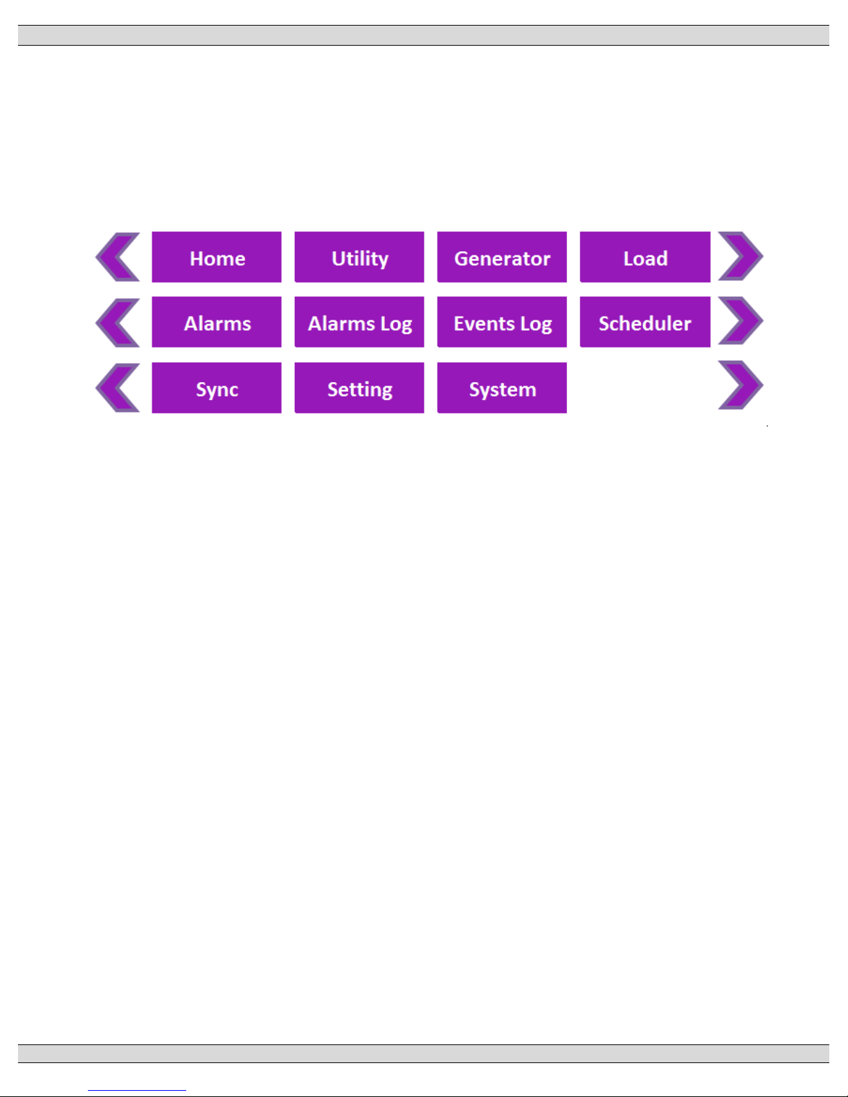
3.5. GHC DISPLAY MAIN MENU PAGE DESCRIPTIONS
The GHC software provides the TSC 900 control and monitoring information which is visible on
the GHC Display or remote PC. All screen page navigation is controlled by a touchscreen display
using a “finger swipe” motion and/or button press actions. The GHC has pre-programmed
display pages which are selected manually using the touchscreen display. The display pages
are organized into the following main menu pages in software:
Note: the “Sync” page will only be visible for ATS applications that are capable of fast in-sync
transfer
Page 34
TSC 900 TRANSFER SWITCH CONTROLLER
PM 151 REV 5 16/04/19 Thomson Power Systems
26
3.5.1. HOME PAGE
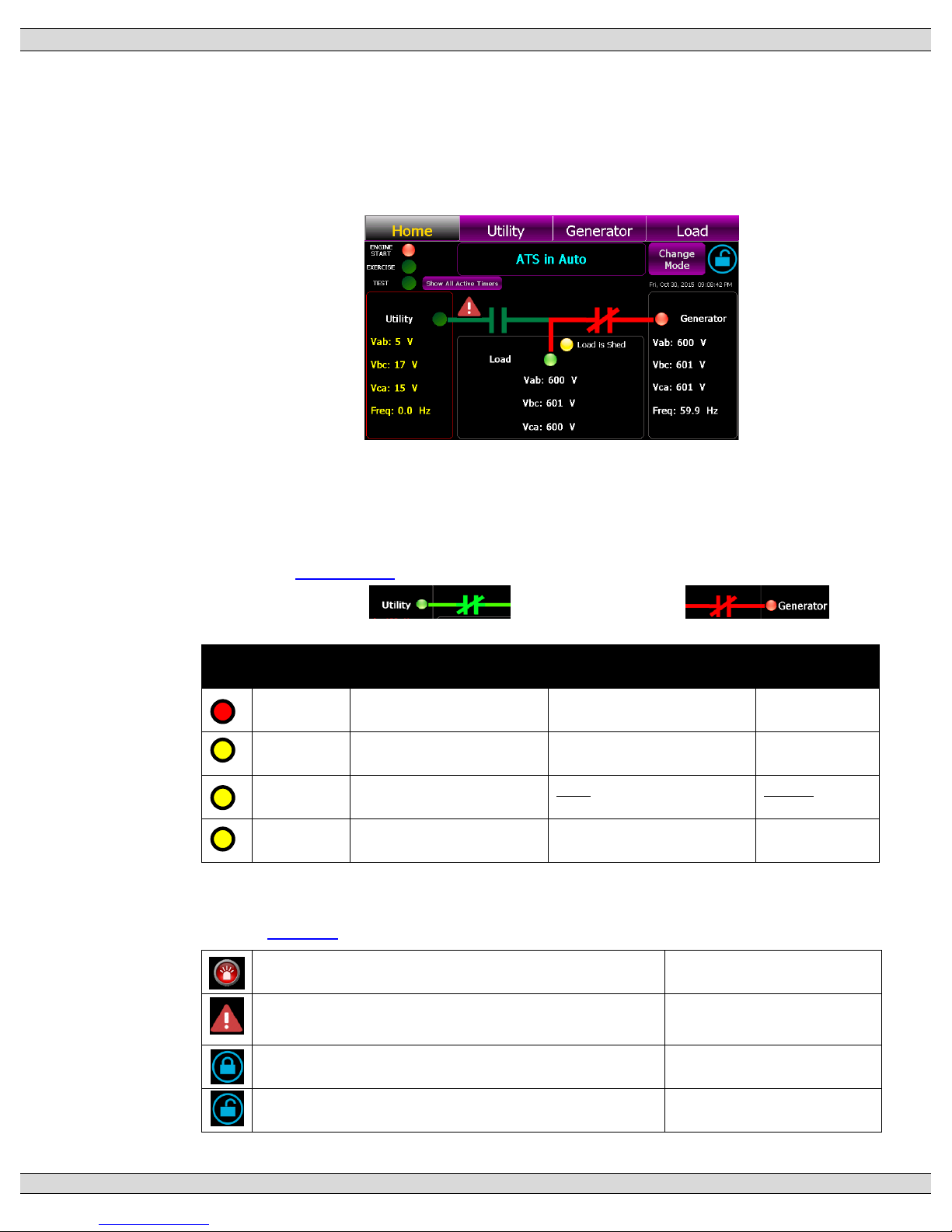
The Home Page is utilized as a summary control and monitoring screen for the ATS.
This screen provides a mimic bus showing current ATS position, identifies which sources
are energized, voltage levels and overall ATS operating mode. Phase to phase system
voltages will be displayed for each source and load.
The standard default mimic bus will automatically change color as follows:
• Utility –dark green = de-energized, light green = energized
• Generator - dark green = de-energized, red = energized
Note: Mimic Bus colors maybe customized to alternate colors.
Refer to Section 3.6.9 Power Switching Device status is depicted as follows:
• Utility Closed: Generator Closed:
The following Status LEDs are shown on the Home page:
LED
Label
Light Off
Light On
Light Flashing
Engine
Start (RED)
Engine is not commanded to
start/run
Engine is commanded to
start/run
n/a
Exercise
(Yellow)
Exercise Schedule is not
enabled or active
Exercise Schedule is enabled
but not currently active
Exercise is
currently active
Test
(Yellow)
Test is not active
Local Test is active (On Load
or Off Load)
Remote Test is
active
Load Shed
(Yellow)
Load Shed is not active
Load Shed is activated
n/a
Test or Timed test modes can be activated from the Home page by press of the “Change
Mode” button which activates a pull down menu.
Refer to Section 5 of this manual for operating procedures.
Alarm Icon –flashes when a new Alarm has been activated
Press to view active alarms
Alert Icon -flashes when a source changes to an abnormal
condition
Press to view active voltage
source alerts
Security Icon - Settings Locked (Read only mode)
Press to access security login
Security Icon - Settings Un-Locked (Read/write mode)
Press to access security login
Page 35
TSC 900 TRANSFER SWITCH CONTROLLER
PM 151 REV 5 16/04/19 Thomson Power Systems
27
3.5.2. UTILITY METERING PAGE
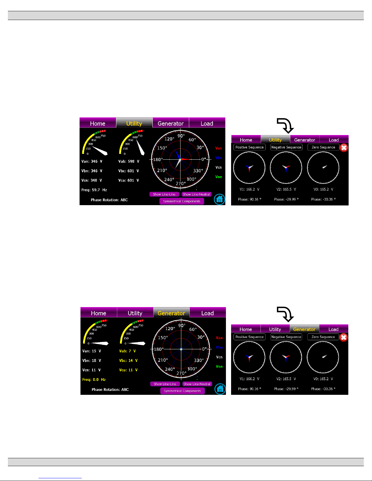
The utility metering page provides detailed voltage and frequency metering data for the
utility supply. Metering data is displayed in both text and graphical representation. Phase
to phase and phase to neutral voltages are displayed as well as a Phasor diagram
showing relative phase angles and magnitudes between phases. A shortcut button is
provided to access the Utility Symmetrical components information screen as follows:
3.5.3. GENERATOR METERING PAGE
The generator metering page provides detailed voltage and frequency metering data for
the generator supply. Metering data is displayed in both text and graphical
representation. Phase to phase and phase to neutral voltages are displayed as well as
a Phasor diagram showing relative phase angles and magnitudes between phases. A
shortcut button is provided to access the Generator Symmetrical components
information as shown for Utility Metering.
Page 36
TSC 900 TRANSFER SWITCH CONTROLLER
PM 151 REV 5 16/04/19 Thomson Power Systems
28
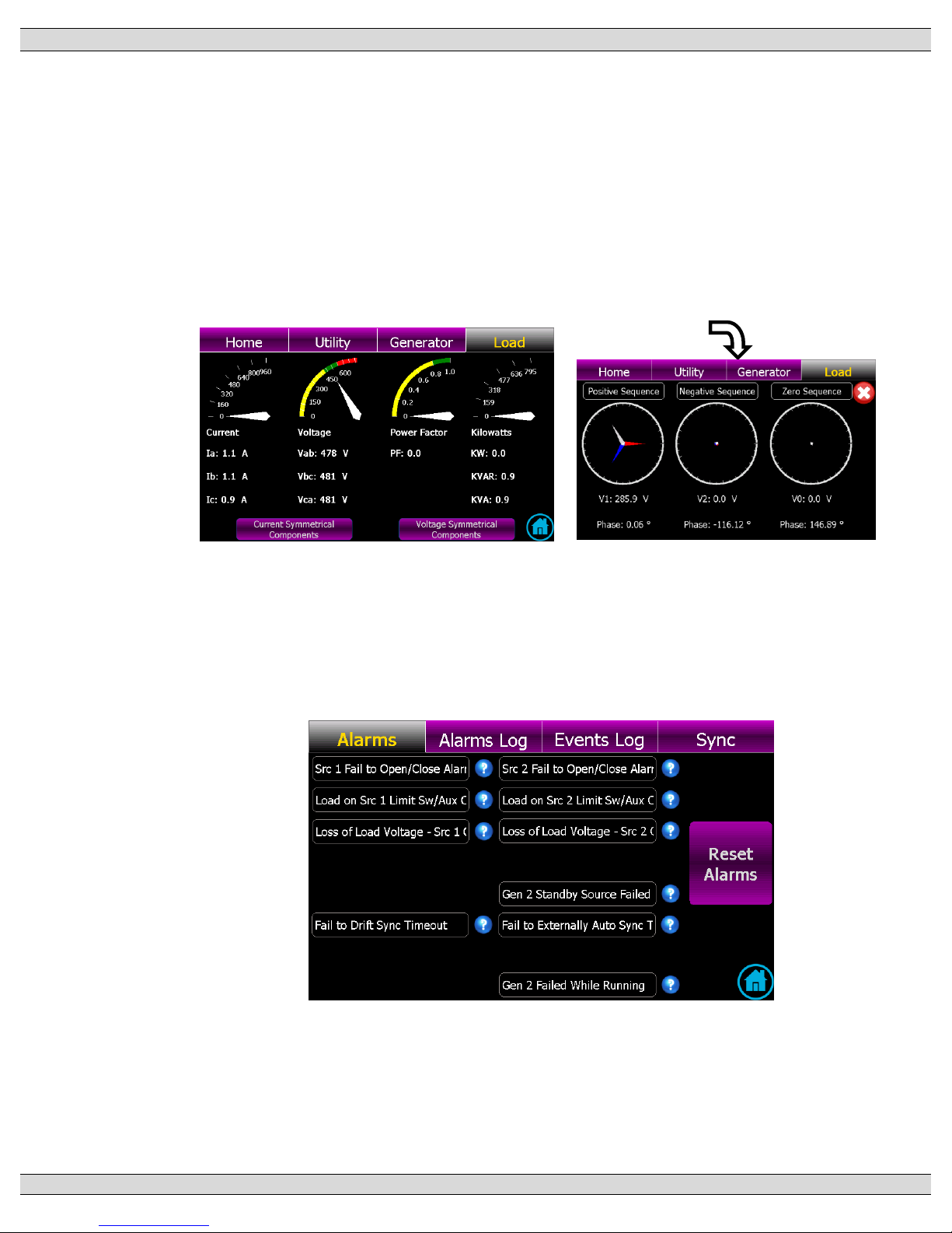
3.5.4. LOAD METERING PAGE
The load metering page provides detailed voltage, current and power metering data for
the ATS load bus. Metering data is displayed in both text and graphical representation.
Phase to phase voltages are displayed. A shortcut button is provided to access the Load
Bus Symmetrical components information.
Note: Load CT and/or Load Power Metering options must be supplied with the ATS to
provide load current and power data.
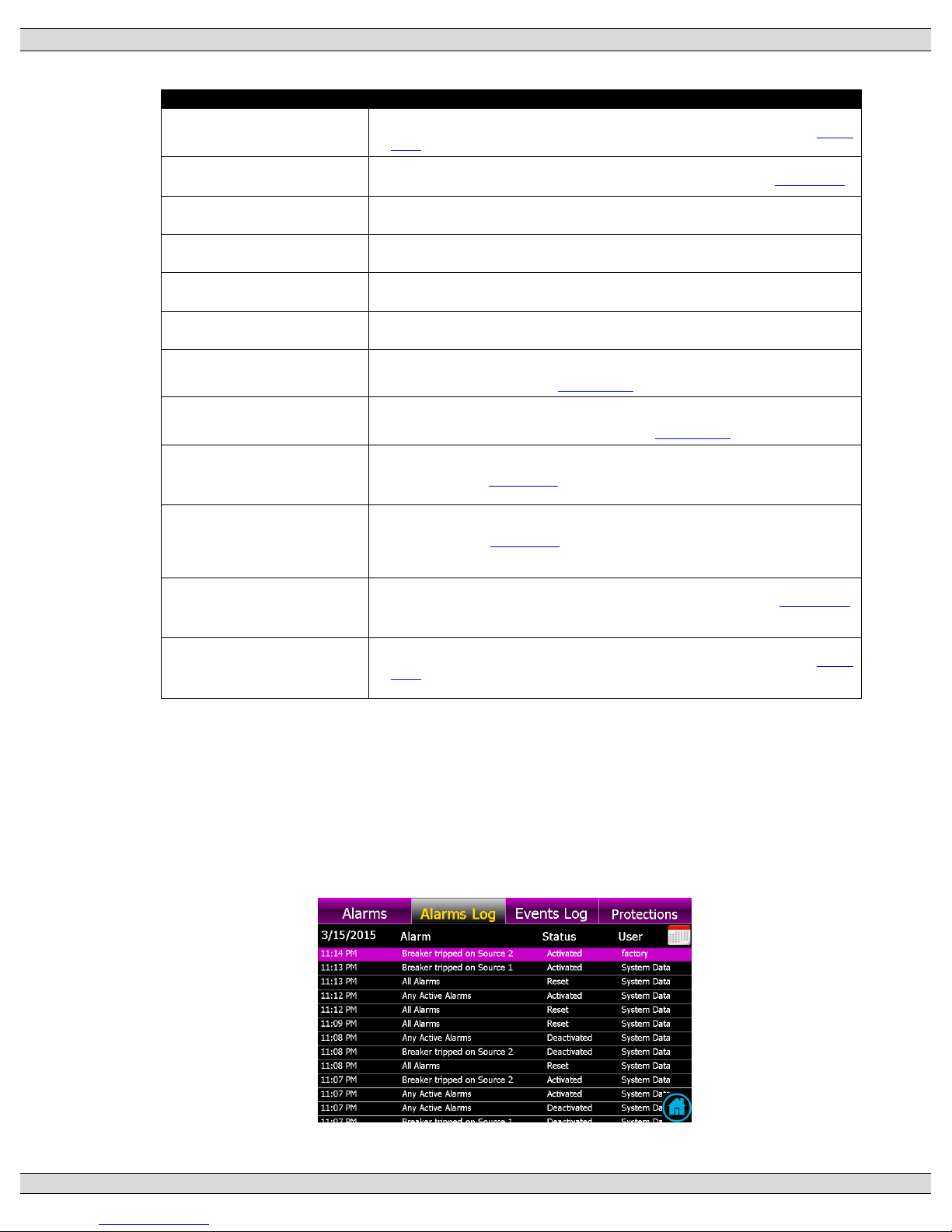
3.5.5. ALARMS PAGE
The TSC 900 alarms page displays available alarms based on the model type of ATS
supplied. Any active alarms will be highlighted with Red background fill. A reset button
is provided on this page to reset all activated alarms. The following is a screen shot for
a standard open transition ATS.
Page 37
TSC 900 TRANSFER SWITCH CONTROLLER
PM 151 REV 5 16/04/19 Thomson Power Systems
29
The following Alarms are provided on the TSC 900
ALARM NAME
ALARM DESCRIPTION
Src 1 Fail to Open/Close Alarm
TAG: alm.xfr.mech.1
Alarm is activated if the Src 1 (Utility) power switching device fails to open or close during a
transfer sequence within the pre-defined time period. Time delay is programmable –see Section
5.12.9.
Src 2 Fail to Open/Close Alarm
TAG: alm.xfr.mech.2
Alarm is activated if the Src 2 (Gen) power switching device fails to open or close during a transfer
sequence within the pre-defined time period. Time delay is programmable –see Section 5.12.9.
Load on Src 1 Limit Sw/Aux Contact
Failure
TAG: alm.xfr.detect.1
Alarm is activated if the “Load On Utility” (Src 1) input signal to the TSC 900 is lost during normal
operation, while the Utility is supplying the load.
Load on Src 2 Limit Sw/Aux Contact
Failure
TAG: alm.xfr.detect.2
Alarm is activated if the “Load On Generator” (Src 2) input signal to the TSC 900 is lost while the
Generator is running and is supplying the load.
Loss of Load Voltage -SRC 1
Contacts Open
TAG: alm.xfr.trip.1
Alarm is activated if the ATS is in the Utility (SRC 1) position and its power switching device
contacts open causing a loss of ATS load voltage.
Loss of Load Voltage -SRC 2
Contacts Open
TAG: alm.xfr.trip.2
Alarm is activated if the ATS is in the Generator (SRC 2) position and its power switching device
contacts open causing a loss of ATS load voltage.
Gen 2 Standby Source Failed to
Start
TAG: alm.gen.muststart.2
Alarm is activated if the standby selected genset (Gen 2) fails to start and reach nominal voltage
and frequency within a pre-defined time period from when an engine start signal was initiated.
Time delay is programmable –see Section 5.12.11.
Gen 1 Standby Source Failed to
Start
TAG: alm.gen.muststart.1
On Dual Gen systems, alarm is activated if the standby selected genset (Gen 1) fails to start and
reach nominal voltage and frequency within a pre-defined time period from when an engine start
signal was initiated. Time delay is programmable –see Section 5.12.11.
Fail to Drift Sync Timeout
TAG: alm.xfr.sync
Alarm is activated if a transfer to alternate source is initiated and the two sources fail to Draft Sync
and reach acceptable synchronization limits within the pre-defined time period. Time delay is
programmable –see Section 5.16.1. Alarm is only active on Transfer switches configured for Open
Transition-in Sync (Model X) or Closed Transition (Fast or Soft-load Models 3 / 4)
Fail to Externally Auto Sync Timeout
TAG: alm.xfr.sync.ext
Alarm is activated if a transfer to alternate source is initiated and the two sources fail to Auto Sync
and reach acceptable synchronization limits within the pre-defined time period. Time delay is
programmable –see Section 5.16.2. Alarm is only active on Transfer switches configured with an
external automatic synchronizer used in Closed Transition (Fast or Soft-load (Models 3 / 4)
applications.
Src 1 Fail to Unload
TAG: alm.xfr.unload.1
Alarm is activated if during a Closed Transition Transfer sequence, the utility supply (SRC 1) fails
to unload within the pre-defined time period. Time delay is programmable –see Section 5.16.3.
Alarm is only active on Transfer switches configured with an external load sharing controller used
in Closed Transition Soft-load (Model 4) applications.
Src 2 Fail to Unload
TAG: alm.xfr.unload.2
Alarm is activated if during a Closed Transition Transfer sequence, the generator supply (SRC 2)
fails to unload within the pre-defined time period. Time delay is programmable –see Section
5.16.3. Alarm is only active on Transfer switches configured with an external load sharing
controller used in Closed Transition Soft-load (Model 4) applications.
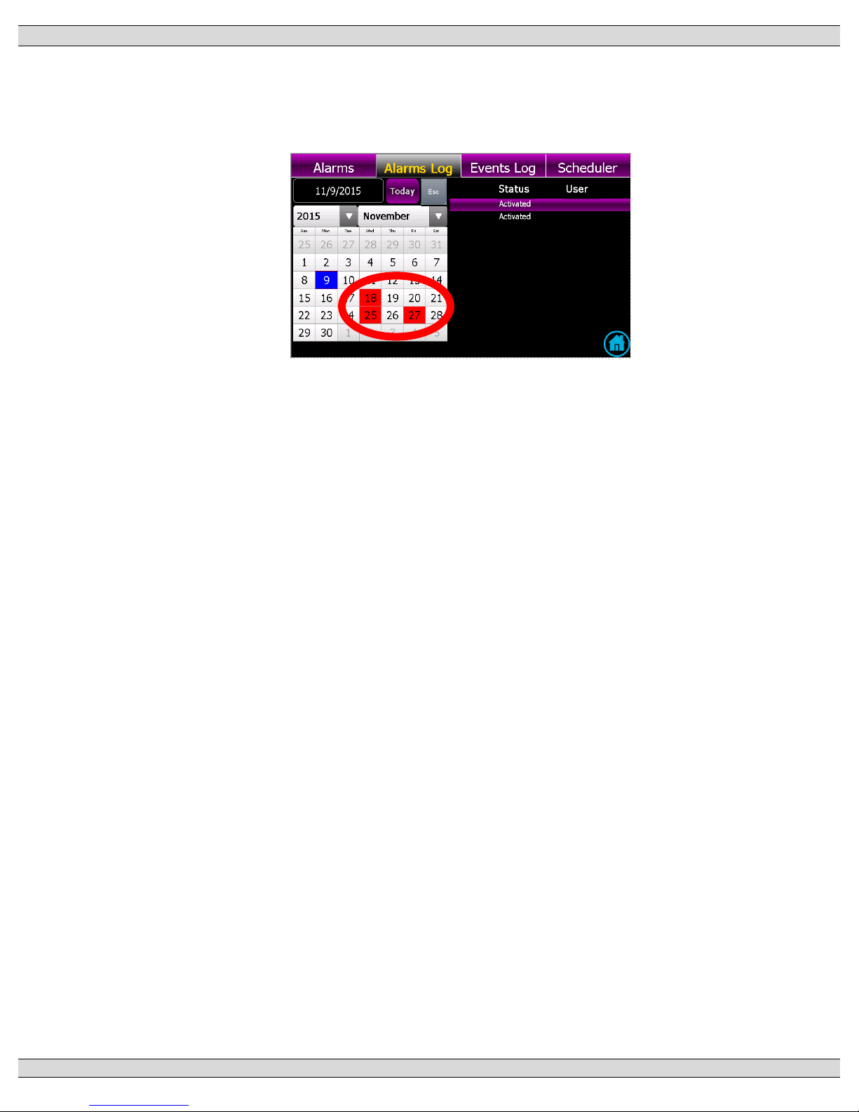
3.5.6. ALARMS LOG PAGE
The alarms log page shows time/date stamped information as to when alarms have
occurred. A drop down menu is provided to select a desired filter to view the logs.
Note: A calendar date must be selected for the desired date to determine if any logs are
visible on that date.
Page 38
TSC 900 TRANSFER SWITCH CONTROLLER
PM 151 REV 5 16/04/19 Thomson Power Systems
30
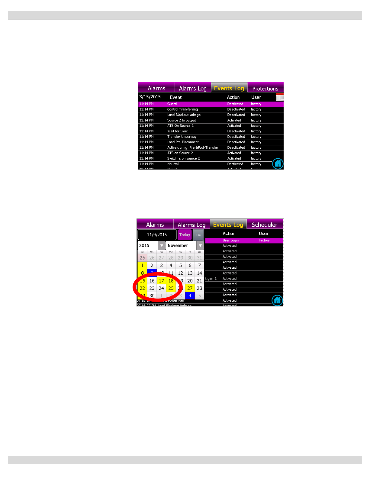
When the Calendar pop-up is selected, any calendar dates with alarm logs present will
be highlighted by a “red” box on that date as per the following display.
Page 39
TSC 900 TRANSFER SWITCH CONTROLLER
PM 151 REV 5 16/04/19 Thomson Power Systems
31
3.5.7. EVENTS LOG PAGE
The events log page shows time/date stamped information as to when events have
occurred. A drop down menu is provided to select a desired filter to view the logs.
Note: A calendar date must be selected for the desired date to determine if any logs are
visible on that date.
When the Calendar pop-up is selected, any calendar dates with Event logs present will
be highlighted by a “yellow” box on that date as per the following display.
Page 40
TSC 900 TRANSFER SWITCH CONTROLLER
PM 151 REV 5 16/04/19 Thomson Power Systems
32
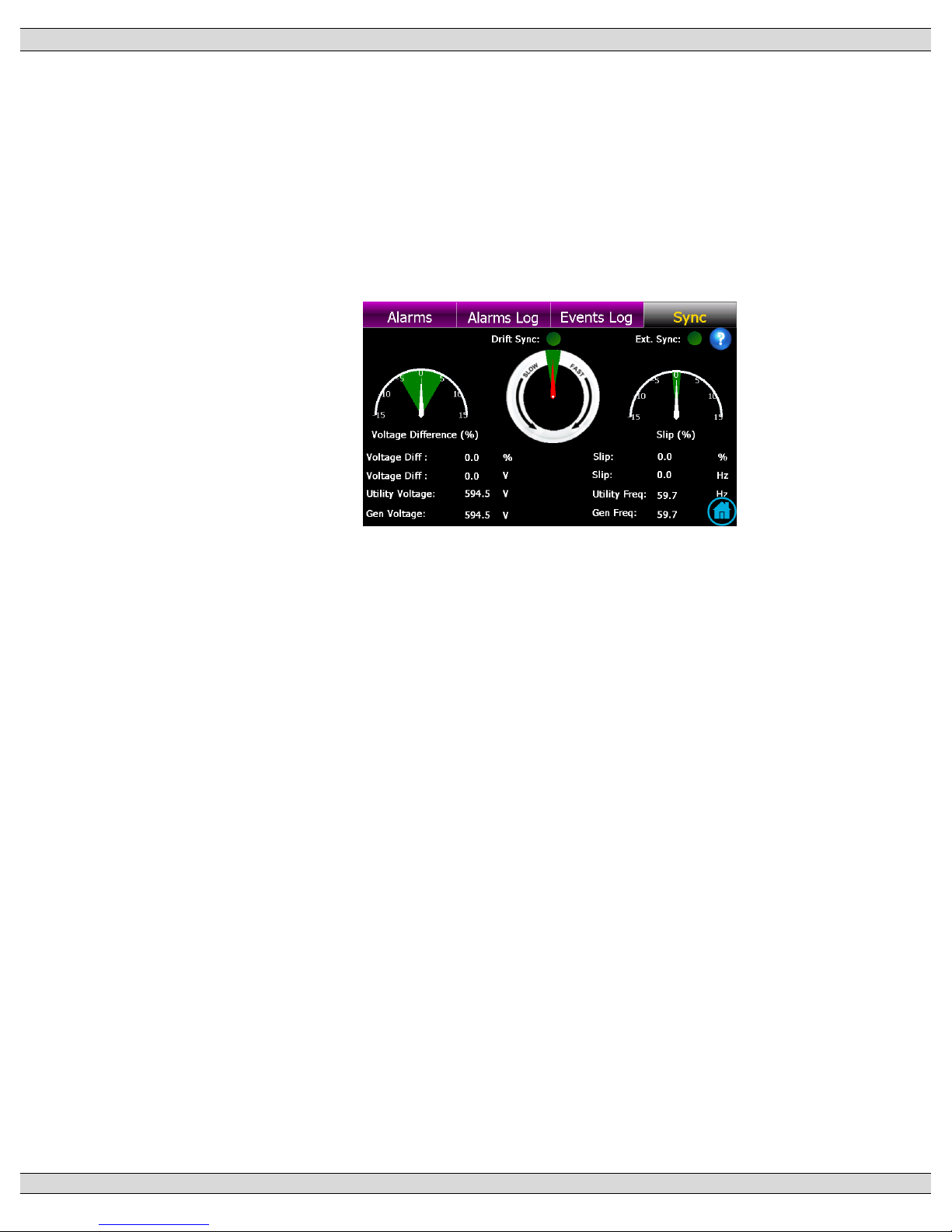
3.5.8. SYNC PAGE
The SYNC page is utilized for applications when the ATS is provided with closed
transition or open transition in-sync transfer capability. This page will display the phase
angle difference, voltage difference and slip frequency difference between two available
sources.
Note: The Sync page is only visible if the ATS model is capable of closed transition
transfer operation or open transition in-sync transfer operation.
Page 41
TSC 900 TRANSFER SWITCH CONTROLLER
PM 151 REV 5 16/04/19 Thomson Power Systems
33
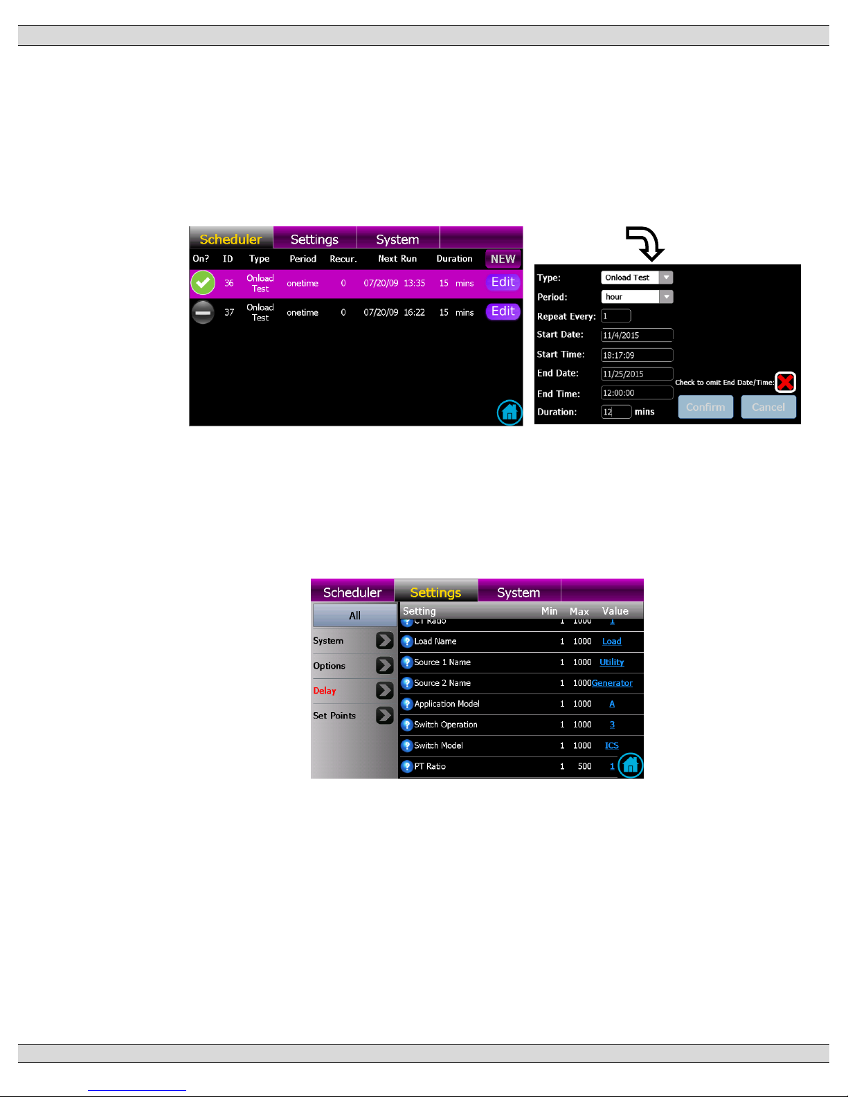
3.5.9. SCHEDULER PAGE
The scheduler page is utilized to set on load or off-load Exercise events using a calendar
based scheduler. Multiple exercise events, dates and times can be selected. By
pressing the “New” or “Edit” buttons a pop-up menu will appear as shown below. Refer
to Operating Instruction section of this manual for further details on how to configure the
Exercise Scheduler.
3.5.10. SETTINGS PAGE
The settings page is utilized for programming or configuring any timer, voltage set point,
frequency set point, I/O mapping or optional features in the controller. The settings can
be viewed via different filter settings based on function. Refer to the Programming section
of this manual for further details on function programming.
Page 42
TSC 900 TRANSFER SWITCH CONTROLLER
PM 151 REV 5 16/04/19 Thomson Power Systems
34
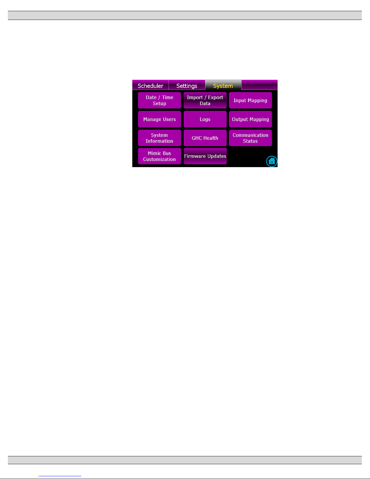
3.5.10 SYSTEM PAGE
The System Page is utilized for viewing or programming specific settings based on the
application. Each System sub-menu page can be viewed by selecting the specific button.
Refer to Section 3.6 for description of each submenu.
Page 43
TSC 900 TRANSFER SWITCH CONTROLLER
PM 151 REV 5 16/04/19 Thomson Power Systems
35
3.6. GHC DISPLAY SYSTEM SUBMENU PAGE DESCRIPTIONS
The system page is utilized for viewing and/or programming site specific settings based on the
application. Different sub-menu pages are available as shown below. Each System sub-menu
pages can be viewed by selecting the specific button. Refer to Section 5 for programming
description of each submenu. Note: To exit any submenu, press the red x icon.
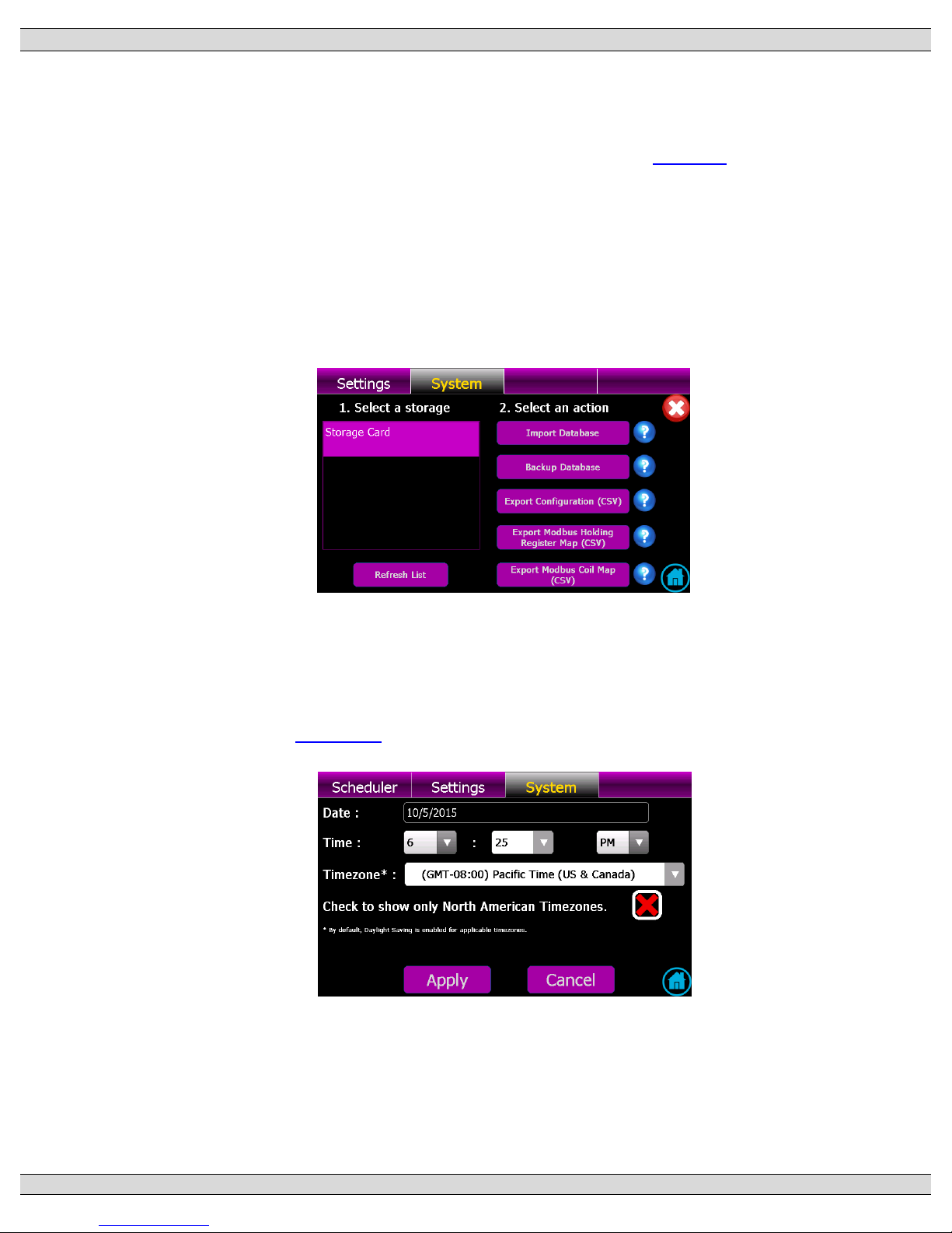
3.6.1. IMPORT/EXPORT DATA
The import/back-up data page is utilized for importing either new program settings or
updated firmware. Current controller settings can also be backed-up or restored from the
GHC SD memory card. Refer to the Programming section of this manual for further
details on import/back-up operating procedures.
3.6.2. DATE / TIME SETUP
The date/time setup page is utilized for changing the TSC 900 real time clock settings to
match the installed location.
Refer to the Section 5.4 for further details on time/date change procedures.
Page 44
TSC 900 TRANSFER SWITCH CONTROLLER
PM 151 REV 5 16/04/19 Thomson Power Systems
36
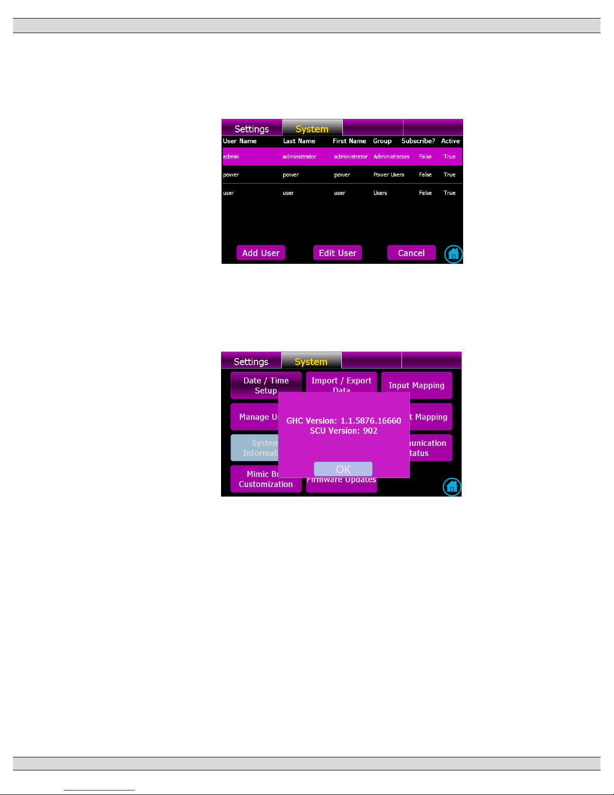
3.6.3. MANAGE USERS
The manage users page shows what users currently exist in the controller and allows
new users to be added as required. Refer to the Programming section of this manual for
further details on editing or adding new users.
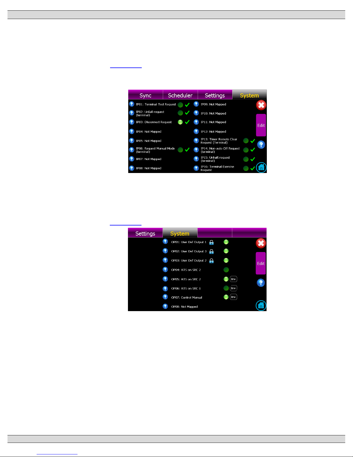
3.6.4. SYSTEM INFORMATION
The System page shows what current firmware versions are installed on the TSC 900
controller.
Page 45
TSC 900 TRANSFER SWITCH CONTROLLER
PM 151 REV 5 16/04/19 Thomson Power Systems
37
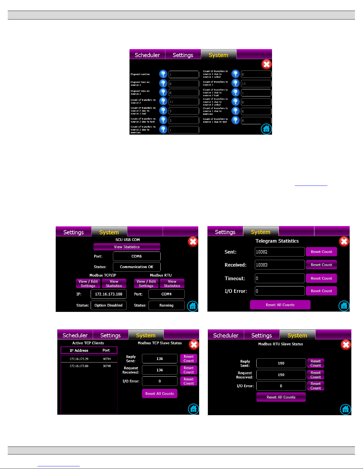
3.6.5. INPUT MAPPING
The input mapping page shows what functions the TSC 900 programmable digital inputs
are configured for and which inputs are currently activated.
Refer to the Section 5.8 of this manual for further details on configuring the digital input
mappings.
3.6.6. OUTPUT MAPPING
The output mapping page shows what functions the TSC 900 programmable relay output
are configured for and which outputs are currently activated.
Refer to the Section 5.9 of this manual for further details on configuring the relay output
mappings.
Page 46
TSC 900 TRANSFER SWITCH CONTROLLER
PM 151 REV 5 16/04/19 Thomson Power Systems
38
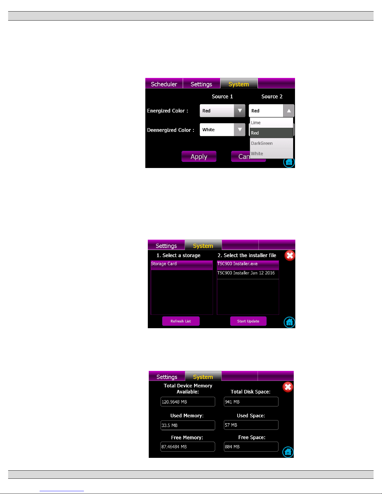
3.6.7. LOGS
The logs page shows the available data logs the controller is logging on a real-time basis.
3.6.8. COMMUNICATION STATUS
The communication status page shows status of all TSC 900 controller communication ports
including Serial (RS232) port, Ethernet (TCP/RTU) ports and the SCU-GHC USB ports. Specific
com port settings and operating statistics can be accessed via this screen. Refer to Section 5.6
for remote communication set-up programming information. For further information on remote
com settings and/or Modbus data addressing, refer to separate product manual PM0152 “TSC
900 MODBUS COMMUNICATION MANUAL”.
Page 47
TSC 900 TRANSFER SWITCH CONTROLLER
PM 151 REV 5 16/04/19 Thomson Power Systems
39
3.6.9. MIMIC BUS CUSTOMIZATION
The mimic bus customization page allows the colors of the Home Page mimic bus to be
changed to a different color scheme as desired. Changing mimic bus colors requires
login security level of “Power” or higher.
3.6.10. FIRMWARE UPDATES
The firmware updates page allows the user to update new firmware in the GHC display
and/or the SCU controller. Contact Thomson Power Systems for applicable Service
Bulletin which details the GHC and SCU firmware update procedure.
3.6.11. GHC HEALTH
The GHC health page provides diagnostic information for the GHC with regards to
memory utilization.
Page 48
TSC 900 TRANSFER SWITCH CONTROLLER
PM 151 REV 5 16/04/19 Thomson Power Systems
40
4. OPERATING INSTRUCTIONS
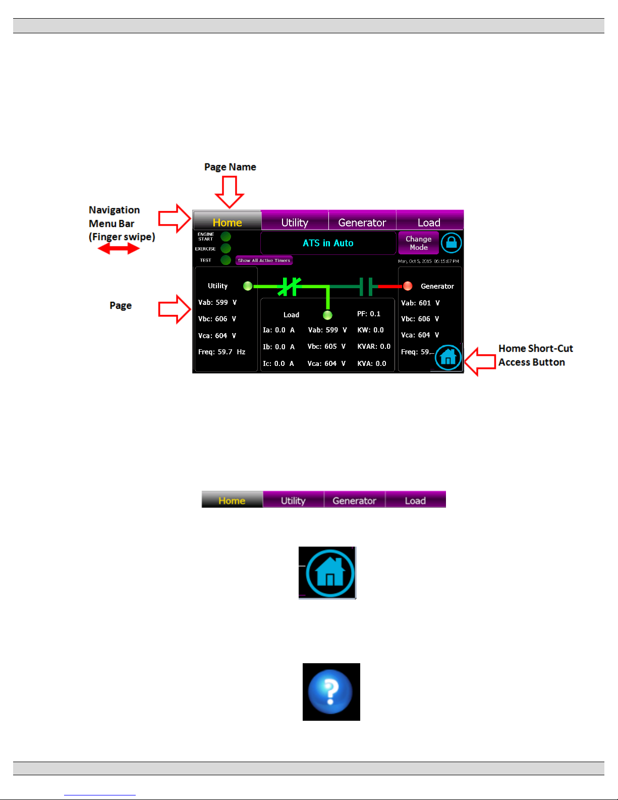
The GHC software provides the TSC 900 control and monitoring information which is visible on the
GHC Display or remote PC. All screen page navigation is controlled by a touchscreen display using a
“finger swipe” motion and/or button press actions. The GHC has pre-programmed display pages which
are selected manually using the touchscreen display. The following screen naming conventions will be
used throughout the document when describing the GHC software screens:
4.1. GHC SCREEN PAGE NAVIGATION
Two methods are available to manually select a desired screen page as follows:
1) Navigation Menu Bar –a finger swipe motion can be used (swipe left or right) on the
menu bar itself.
2) Home Short-Cut Button - To directly access the Home Page from any screen press
the following ICON:
4.2. HELP INFORMATION
Help Information screens are available whenever a question mark Icon is displayed. Press the
Icon to open up further information on the specific item.
Page 49
TSC 900 TRANSFER SWITCH CONTROLLER
PM 151 REV 5 16/04/19 Thomson Power Systems
41
4.3. ON LOAD TEST INSTRUCTIONS (UTILITY POWER FAIL SIMULATION)
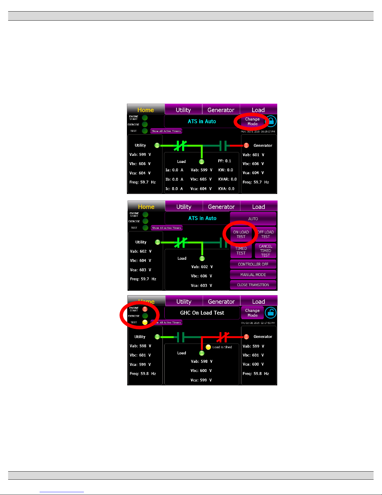
To perform an On Load Test and simulate a utility power fail condition, press the “Change Mode”
control button on the GHC Home Page and select “ON LOAD TEST” mode from the available
list of modes as shown below. The “TEST” light on the upper left-hand corner of the screen will
turn Yellow to indicate mode is activated and the “ENGINE START” light will turn Red. The
generator will start and transfer on load per Automatic Sequence.
Page 50
TSC 900 TRANSFER SWITCH CONTROLLER
PM 151 REV 5 16/04/19 Thomson Power Systems
42
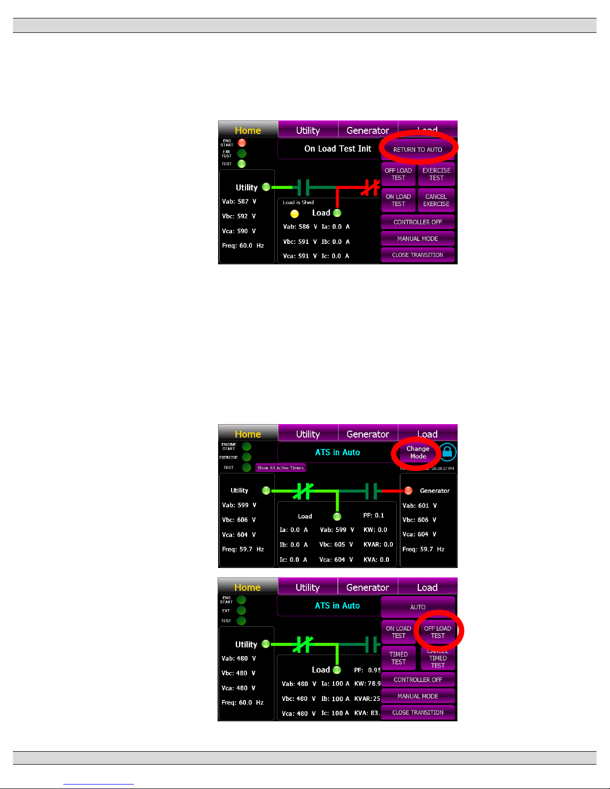
To cancel On Load Test, press the “Change Mode” control button on the GHC Home Page and
select “RETURN TO AUTO” mode from the available list of modes as shown below. The “Test”
and “Engine Start” lights on the upper left-hand corner of the screen will go off and the load will
re-transfer back to the utility power per Automatic Sequence.
4.4. OFF LOAD TEST INSTRUCTIONS (GENERATOR NO LOAD TEST)
To perform an “Off Load” Test mode to run the generator set without transferring on load, press
the “Change Mode” control button on the GHC Home Page and select “OFF LOAD TEST” mode
from the available list of modes as shown below. The “TEST” light on the upper left-hand corner
of the screen will turn Yellow to indicate mode is activated and the “ENGINE START” light will
turn Red. The generator will start and transfer on load per Automatic Sequence. The generator
will start and will run continuously.
Page 51
TSC 900 TRANSFER SWITCH CONTROLLER
PM 151 REV 5 16/04/19 Thomson Power Systems
43
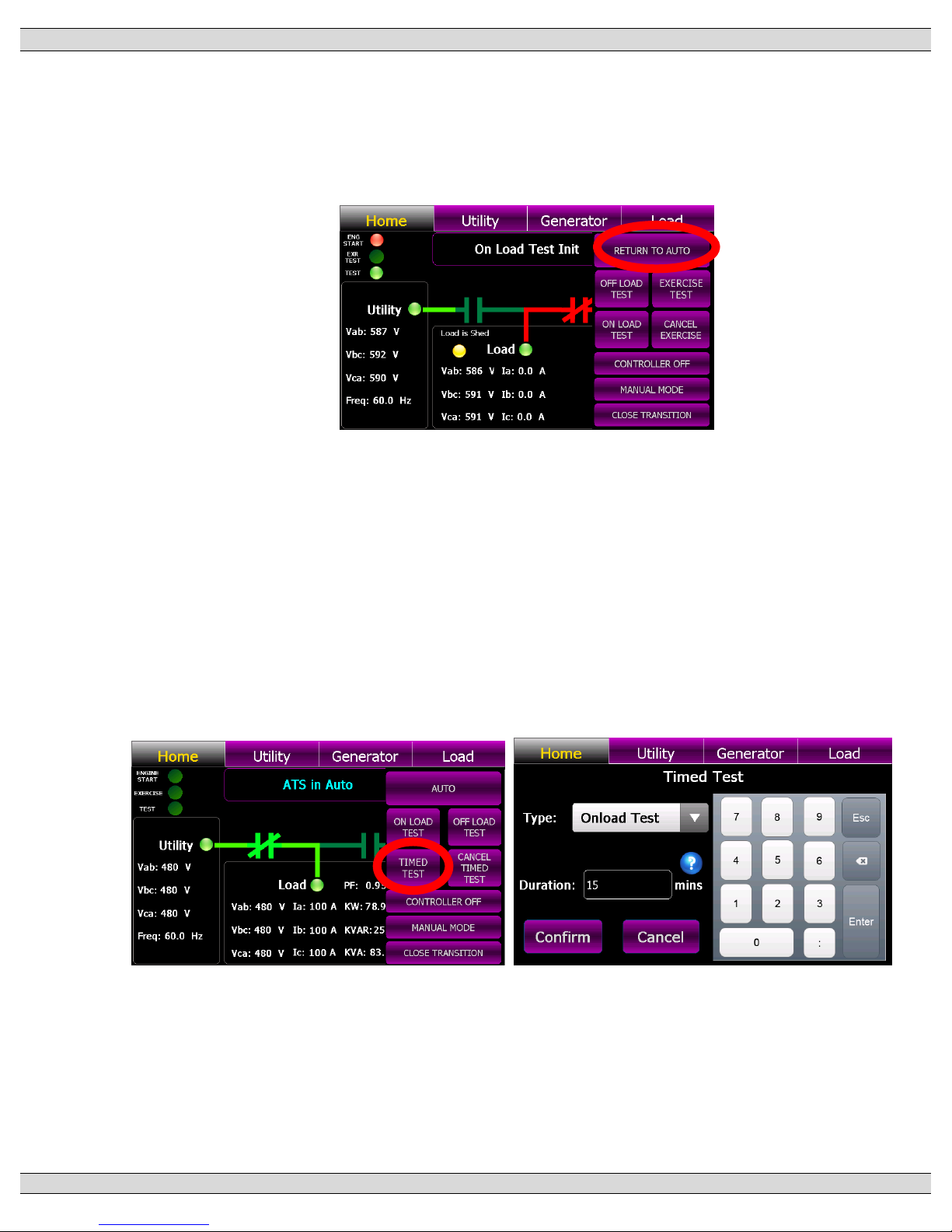
To cancel the “Off load” Test, press the “Change Mode” control button on the GHC Home Page
and select “RETURN TO AUTO” mode from the available list of modes as shown below. The
“Engine Start” light on the upper left-hand corner of the screen will go off and the generator set
will stop.
4.5. TIMED TEST INSTRUCTION
To perform a TIMED TEST, press the “Change Mode” control button on the GHC Home Page
and select “TIMED TEST” mode from the available list of modes as shown below. A Pop-up
screen will appear as shown below. Enter in desired type of test (i.e. ONLOAD or OFFLOAD)
and the duration time in minutes. Once the “Confirmed” button is pressed, the “TEST” light on
the upper left-hand corner of the screen will turn Yellow to indicate mode is activated and the
“ENGINE START” light will turn Red. The generator will start and if selected for On Load test,
the generator will transfer on load per automatic sequence and remain operating on load for the
duration of time entered, then will automatically re-transfer back to the utility supply.
Page 52
TSC 900 TRANSFER SWITCH CONTROLLER
PM 151 REV 5 16/04/19 Thomson Power Systems
44
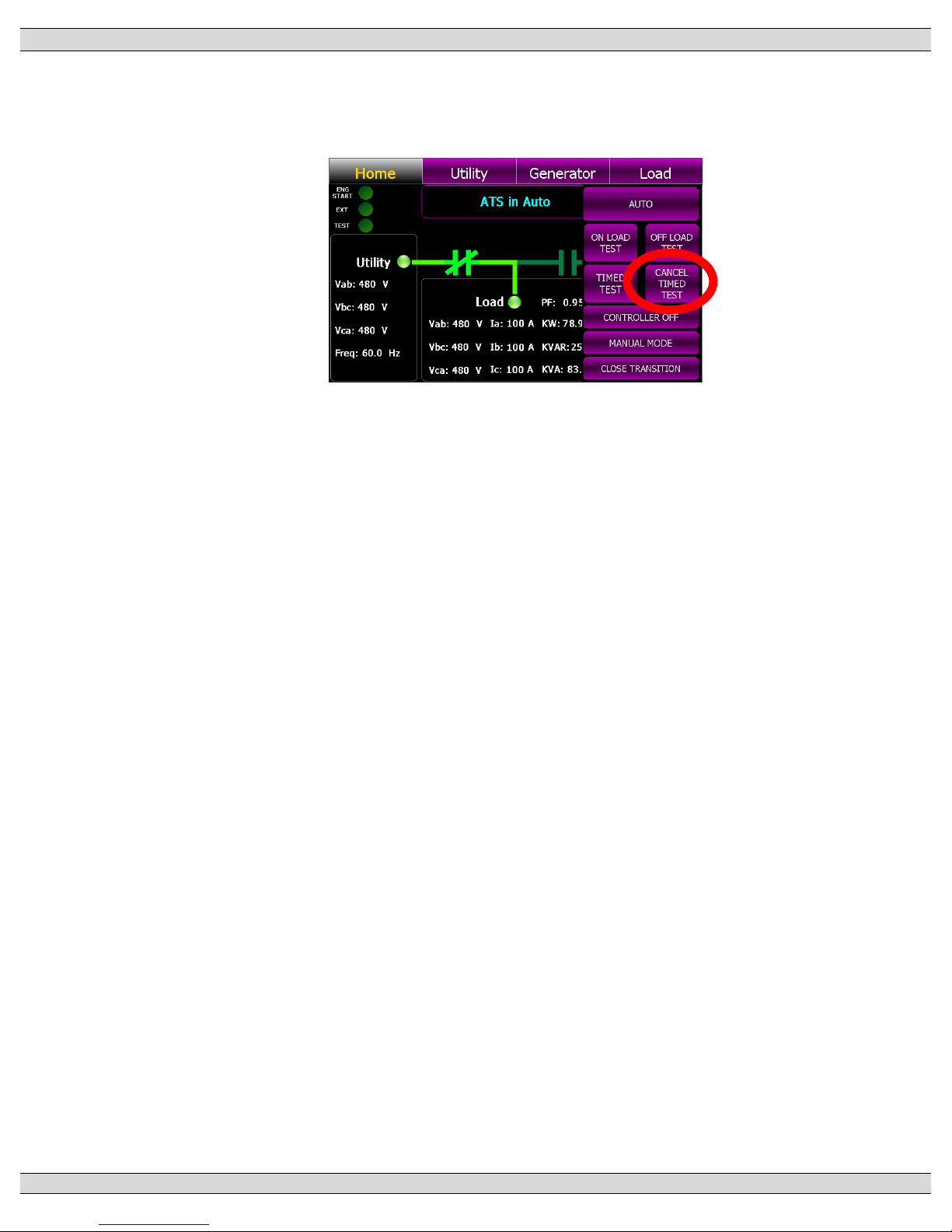
To cancel TIMED TEST mode, press the “Change Mode” control button on the GHC Home Page
and select “CANCEL TIMED TEST” mode from the available list of modes as shown below.
Page 53
TSC 900 TRANSFER SWITCH CONTROLLER
PM 151 REV 5 16/04/19 Thomson Power Systems
45
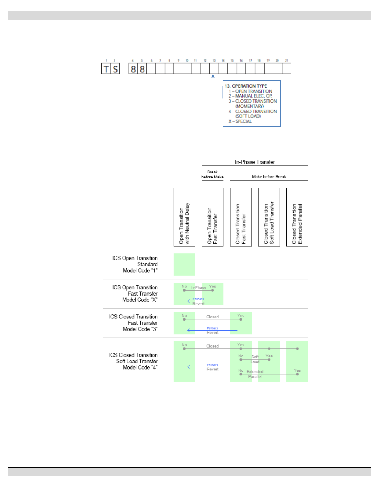
4.6. OPEN/CLOSED TRANSITION TRANSFER OPERATION
The ATS may be supplied with a number of different Open or Closed Transition Transfer
operational features. The ATS model code depicts the options available as shown below:
Operational behavior of an ATS equipped with these different features is depicted in the
following diagram:
Page 54
TSC 900 TRANSFER SWITCH CONTROLLER
PM 151 REV 5 16/04/19 Thomson Power Systems
46
4.6.1. OPEN TRANSITION IN-SYNC TRANSFER OPERATION (MODEL X)
If the ATS is supplied with ATS Model X feature (i.e. Open Transition – In-sync Transfer),
the ATS will operate as per automatic sequence of operation (open transition) however
all transfers will occur using in-sync transfer control sensing instead of neutral delay
control logic. All In-sync transfer operations will occur only when both sources of power
are available and within normal operating limits. Note: Open Transition In-sync Transfer
operation is only possible if the ATS mechanism is equipped for in-sync operation and
optional feature is enabled in Settings. Refer to Section 5.11.26 for further details.
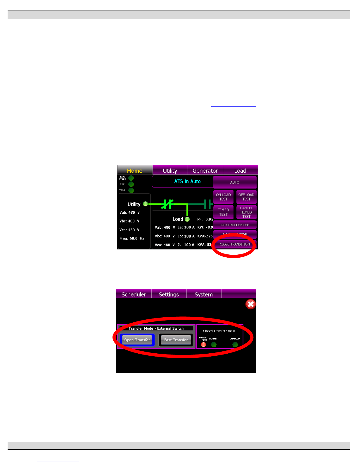
4.6.2. CLOSED TRANSITION OPERATION (FAST TRANSFER MODEL 3)
If the ATS is supplied with Closed Transition Transfer –Fast Transfer (i.e. Model 3)
features, the CLOSED TRANSITION control selection will be provided on the GHC
display via the Change Mode button selection.
When the CLOSED TRANSITION button is selected, a pop-up screen will appear
showing operation mode selections as shown below;
The left-hand side of the display shows the current position of the ATS control modes
(i.e. Open Transfer or Fast (Closed) Transfer) based on current selection of the internal
GHC display buttons or external control switch as maybe provided. To change between
operating modes, select desired operation using the GHC display buttons or external
switch as provided.
Page 55
TSC 900 TRANSFER SWITCH CONTROLLER
PM 151 REV 5 16/04/19 Thomson Power Systems
47
The right-hand side of the display shows the status of the Closed Transition Transfer
“Permit” or Inhibit” signals. Depending on the operating status of the ATS, Closed
Transition Transfer will be inhibited should only 1 source of supply be available or
Protection Lock-out relay has been activated. Note: Closed Transfer operation is only
possible if the optional feature is enabled in Settings. Refer to Section 5.11.17 for further
details.
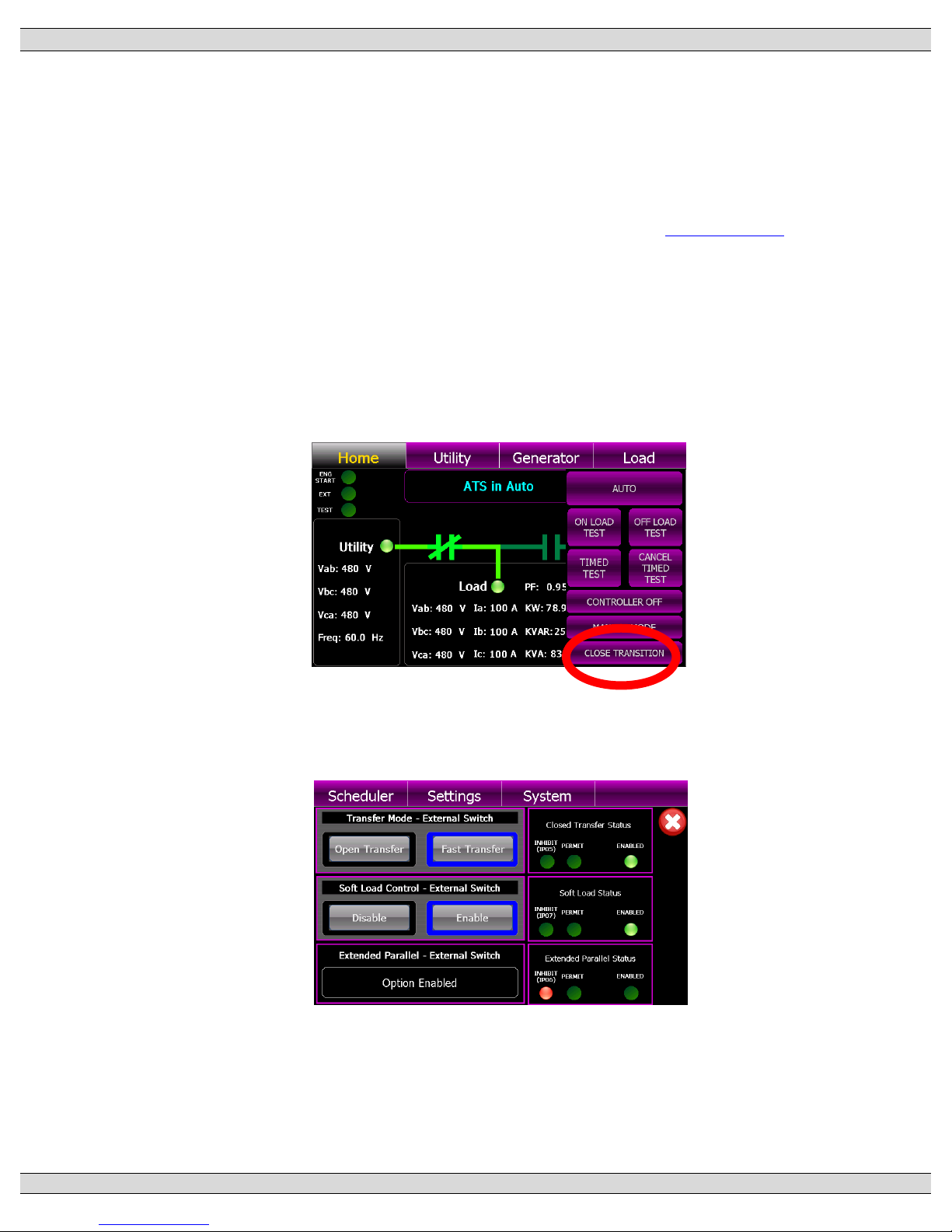
4.6.3. CLOSED TRANSITION OPERATION (SOFT-LOAD TRANSFER
MODEL 4)
If the ATS is supplied with Closed Transition Transfer Soft-load Transfer (i.e. Model 4)
features, the CLOSED TRANSITION control selection will be provided on the GHC
display via the Change Mode button selection.
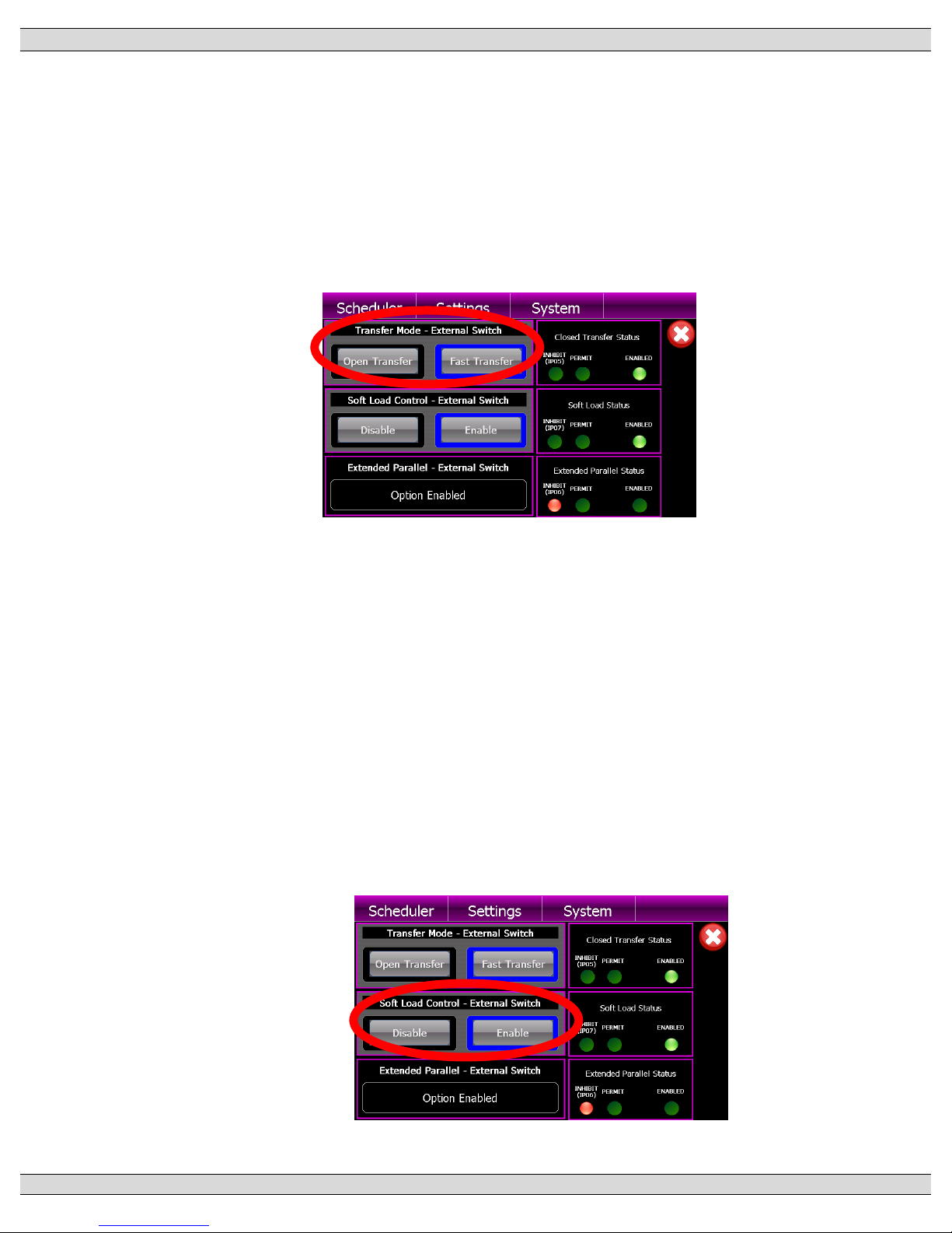
When the CLOSED TRANSITION button is selected, a pop-up screen will appear
showing operation mode selections as shown below;
Page 56
TSC 900 TRANSFER SWITCH CONTROLLER
PM 151 REV 5 16/04/19 Thomson Power Systems
48
The left-hand side of the display shows the current position of the ATS control modes.
Model 4 ATS provides 3 different operating mode via GHC Display button or external
control switches as follows:
4.6.3.1. TRANSFER MODE SELECTION
Transfer mode selection may be done via internal GHC display buttons, or
external control switch. This selection is shown on the GHC display as indicated
below.
This provides operator selection of desired transfer modes as follows;
• OPEN TRANSFER: The ATS will only operate in an Open Transition
transfer (i.e. break-before-make) sequence. The two sources will not be
permitted to operate in parallel under any circumstance.
• FAST TRANSFER: The ATS will operate in a Fast (Closed) Transition
transfer sequence if both sources are available. The two sources will be
permitted to stay in parallel for a maximum of 100 milliseconds only.
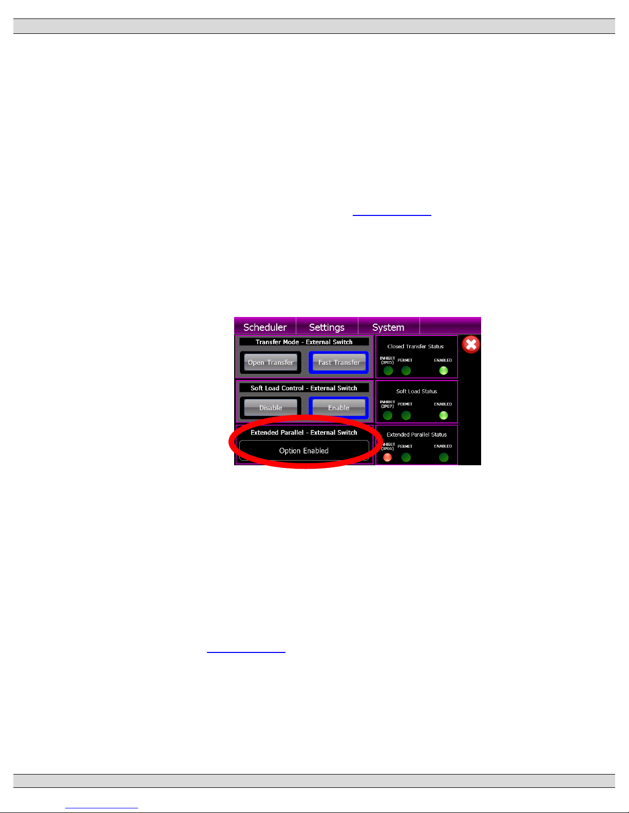
4.6.3.2. SOFT-LOAD CONTROL SELECTION
Soft-Load transfer mode selection may be done via internal control push buttons,
or external control switch. This selection is shown on the GHC display as
indicated below.
This provides operator selection of desired operating modes as follows;
Page 57
TSC 900 TRANSFER SWITCH CONTROLLER
PM 151 REV 5 16/04/19 Thomson Power Systems
49
• DISABLE: The Soft-Load operating mode is disabled in this mode. The
ATS will operate in either Open or Closed Transition Fast Transition as
selected.
• ENABLE: The ATS will operate in a Soft-Load Closed Transition transfer
sequence if both sources are available. The two sources will be permitted
to stay in parallel for a maximum of 10 seconds only to allow loads to be
ramped between the sources by an external controller. Note: Soft-Load
Closed Transition operation is only possible if the optional feature is
enabled in Settings. Refer to Section 5.11.21 for further details.
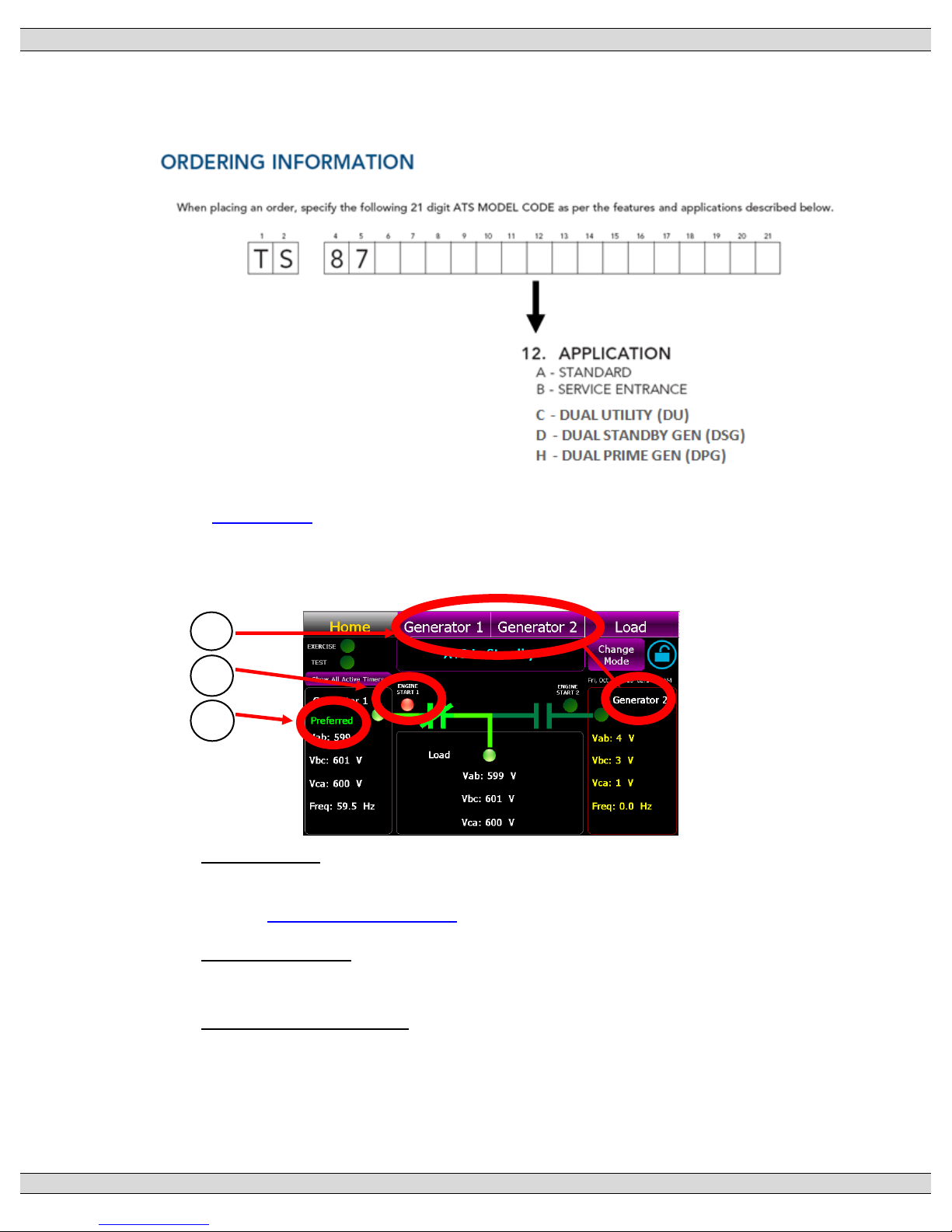
4.6.3.3. EXTENDED PARALLEL SELECTION
Extended Parallel operating mode selection may be done via internal control
push buttons, or external control switch. This selection is shown on the GHC
display as indicated below.
This provides operator selection of desired operating modes as follows;
• OPTION DISABLE: The Extended Paralleling operating mode is
disabled in this mode. The ATS will operate in either Open or Closed
Transition transfer as selected.
• OPTION ENABLED: The ATS will operate with both sources closed to
the ATS load bus for an extended period of time as controlled by an
external device. Note: Extended Parallel Closed Transition operation is
only possible if the optional feature is enabled in Settings. Refer to
Section 5.11.20 for further details.
Page 58
TSC 900 TRANSFER SWITCH CONTROLLER
PM 151 REV 5 16/04/19 Thomson Power Systems
50
4.7. DUAL SOURCE ATS OPERATION
The ATS may be supplied with three different Dual Source Transfer operational features. The
ATS model code depicts the options available as shown below:
Refer to Section 3.4.3 for automatic sequence of operation descriptions for the 3 types of dual
source systems.
Dual source systems will have a unique GHC home page display as shown below:
1. Source Names: Each source will have its unique name displayed on the top navigation
bar as well as adjacent to the mimic bus source inputs. These names are configurable.
Refer to Sections 5.10.9 - 5.10.10 for programming information
2. Engine Start Status: For dual generator applications, two engine start status lights are
provided as indicated above. Red indicates when an engine start is activated.
3. Preferred Source Indication: When a source is selected as the “Preferred source”, it will
be indicated via text as indicated above. Preferred source selection maybe via External
control switch or TSC 900 GHC display.
3
1
2
Page 59
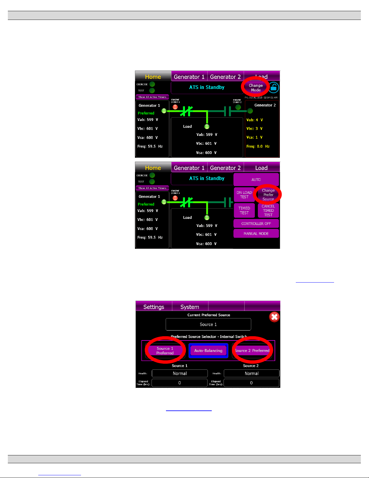
TSC 900 TRANSFER SWITCH CONTROLLER
PM 151 REV 5 16/04/19 Thomson Power Systems
51
4.7.1. DUAL SOURCE - CHANGING PREFERRED UNITS (GHC CONTROL)
To change the “Preferred Source” on an ATS using the GHC screen source selection,
press the “Change Mode” control button on the GHC Home Page and select “CHANGE
PREFER SOURCE” from the available list of modes as shown below.
A Preferred Source selection screen will pop-up as shown below. Using the buttons
provided, select the desired source. Once the new preferred source is selected, the
transfer switch will automatically transfer to the new source as described in Section 3.4.3
provided it is operating at normal voltage and frequency.
To operate the ATS in AUTO-BALANCING operation mode, select the AUTOBALANCING button. Refer to Section 5.11.23 for programming details.
To exit the Preferred Source selection screen, press the Red X icon.
Page 60
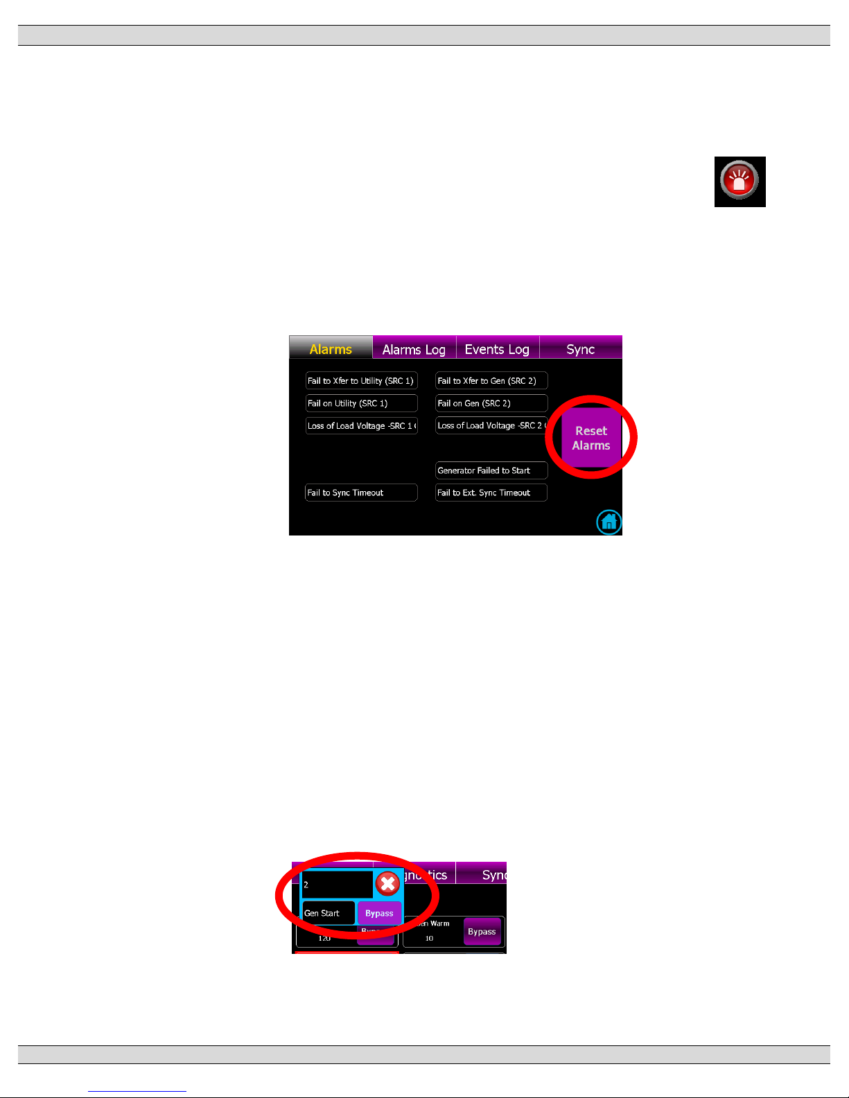
TSC 900 TRANSFER SWITCH CONTROLLER
PM 151 REV 5 16/04/19 Thomson Power Systems
52
4.8. TRANSFER FAIL ALARM RESET
Should a Transfer fail alarm occur, the flashing ALARM ICON will appear on the GHC Home
page as shown below. If the transfer switch is pre-programmed as Force Transfer, the ATS will
automatically transfer to the alternate source (if available) and will still stay locked onto the
alternate source unit the Transfer Fail alarm is manually reset by the ATS operator.
To determine which transfer alarm condition has been triggered, press the ALARM ICON to
navigate to the ALARMS Page as shown below. Once the specific alarm condition has been
determined and the necessary corrective action has been implemented, the alarm can be reset
by pressing the “RESET ALARMS” button.
4.9. TIMER BYPASS
The following automatic sequencing time delays can be temporarily bypassed when the time
function is active as shown on the TSC 900 GHC display:
• Utility Return Timer
• Cooldown Timer
• Warm up Timer
• Neutral Delay Timer
• Pre and Post Transfer Delay
This feature is typically used when testing to avoid waiting for the complete duration of the time
period. To activate the bypass function, press the BYPASS button when the timer is in operation
as displayed on the screen.
NOTE: The Time delay functions will return to the normal time settings on the subsequent
automatic operating sequence.
Page 61
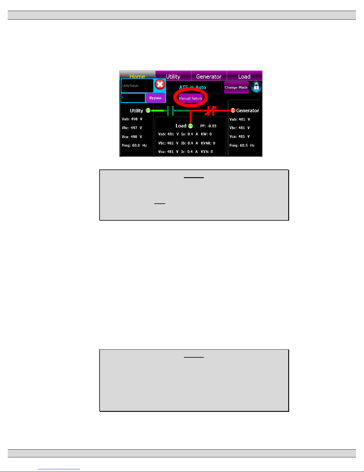
TSC 900 TRANSFER SWITCH CONTROLLER
PM 151 REV 5 16/04/19 Thomson Power Systems
53
4.10. MANUAL UTILITY RETRANSFER CONTROL
If the TSC 900 is pre-programmed to provide a Manual return to the utility supply following a
utility power failure, an operator can decide when to initiate the re-transfer sequence by pressing
the “MANUAL RETURN” button when displayed on the GHC Home page as shown below.
NOTE:
The manual re-transfer sequence will only be initiated if the
button is pressed and the utility supply (source 1) is at nominal
voltage and frequency levels.
4.11. SERVICE DISCONNECT MODE
For transfer switches equipped with the Service Entrance Mode option, the TSC 900 is
configured to provide additional logic for the application. When the TSC 900 controller receives
an input signal from the door mounted Service Disconnect switch to transfer to the neutral
position, the TSC 900 control outputs will change state to cause the ATS mechanism to move
to the neutral position. The ATS operator must wait ~2 seconds to allow the ATS to move to the
neutral position before selecting the “Disconnected” position. When the Service Disconnect
switch is moved to the “Disconnected” position, all transfer logic control outputs from the TSC
900 are disconnected and the engine start signal is disabled. When the Service Disconnect
switch is returned to the “Energized position, the TSC 900 control outputs are re-connected and
will change state to cause the ATS mechanism to transfer back to the Utility position.
NOTE:
For Transfer Switches equipped with the Remote Load Dump
Control (RLDC) feature, Digital input DI03 will be mapped to
Service Disconnect Mode Initiated which is utilized to move the
ATS to the neutral position when RLDC is activated.
Page 62

TSC 900 TRANSFER SWITCH CONTROLLER
PM 151 REV 5 16/04/19 Thomson Power Systems
54
4.12. PHASE UNBALANCE PROTECTION ALARM RESET
When the TSC 900 is programmed with Phase Unbalance protection enabled, should a transfer
occur due to an out of limit phase unbalance condition, an alarm message will be shown on the
TSC 900 GHC display “UTILITY (or GEN) UNBALANCED”. The Phase unbalance feature may
be user programmed to provide two different re-transfer operating sequences (i.e. AUTO or
MANUAL RETRANSFER). When the “AUTO” re-transfer mode is selected, the load will be
automatically re-transferred back to the original source and does not require operator
intervention. When the “MANUAL” retransfer mode is selected, a re-transfer back to the original
source will not occur until the ALARM RESET button is pressed by ATS operator. For further
details on phase unbalance programming refer to Section 5.13.7 up to 5.13.10.
NOTE: When in the MANUAL RETRANSFER mode, if the alternate source fails, the alarm
lockout will not be bypassed inhibiting the load to re-transfer back to the original source even if
within limits. The reason the re-transfer is inhibited is phase unbalance is generally only
detected when load is applied to the source and the condition will appear to clear when the load
is removed, as such allowing a re-transfer to the failed source previously determined to have a
phase balance fault will only result in multiple unnecessary transfers of the load between
sources. Retransfer is set to lockout and requires operator intervention.
Page 63
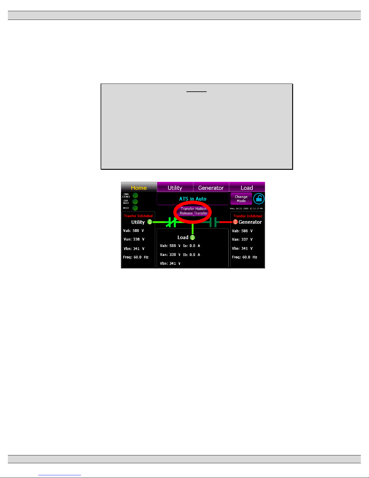
TSC 900 TRANSFER SWITCH CONTROLLER
PM 151 REV 5 16/04/19 Thomson Power Systems
55
4.13. TRANSFER HALTED ALARM RESET
Should a transfer switch failure occur during a transfer to a new intended source, a “TRANSFER
HALTED” alarm will be posted to the GHC home screen as shown below. The transfer switch
will remain in this current position until the Transfer Halted condition is manually reset by ATS
operator utilizing the RELEASE TRANSFER reset button on the GHC home page.
NOTE:
The TRANSFER HALTED condition will be initiated by one of the
following operating conditions:
- Power Switching Device fail to close or open
- Reverse Phase Rotation between connected sources
- Phase unbalance alarm
Page 64
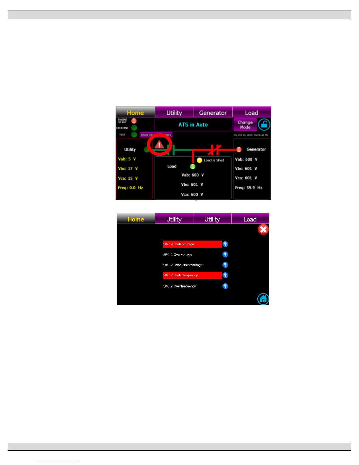
TSC 900 TRANSFER SWITCH CONTROLLER
PM 151 REV 5 16/04/19 Thomson Power Systems
56
4.14. ABNORMAL SOURCE ALERT
Should an abnormal source condition be detected by the TSC 900, a red Source Alert triangle
Icon will automatically start flashing on the home screen as shown below. To view which specific
condition has triggered the alert, press the alert Icon and a pop-up screen will be displayed as
shown below. The Abnormal Source Alert is provided for both Utility (SRC 1) or Gen (SRC 2)
and will automatically reset should the source return to within normal limits. The alert does not
require resetting for automatic operation to resume.
Page 65
TSC 900 TRANSFER SWITCH CONTROLLER
PM 151 REV 5 16/04/19 Thomson Power Systems
57
5. PROGRAMMING INSTRUCTIONS
5.1. PASSWORD SECURITY DESCRIPTION (USERS ADMIN)
To prevent un-authorized access, users are required to “Login” in order to:
• Acknowledge and reset alarms
• Change operating modes
• Change Configuration settings
• Manage Users
• Map Inputs/Outputs
The device security is organized in groups. Using the Users Management screen, a device
Administrator can create new users, enable and disable access for existing users. There is one
default user created for every group: admin, power and user. It is the responsibility of the
installer to ensure the default passwords are changed during ATS commissioning.
Group Name
Rights
Default
User Login
Default
Password
Administrators
Allowed to manage users
admin
pass
Power Users
Allowed to change ATS mode, send
commands in the system and modify
settings
power
pass
Users
Acknowledge and reset alarms,
Manual Return and Un-halt the switch after
a failure
user
pass
Once a user logs in they are not automatically logged out. Action attempts to functions that require
elevated rights will trigger a pop-up message box
Note on Privacy: The GHC is not storing user passwords. Using an encryption mechanism, a
hash of the UserID + Password+ encryption key is created and stored. During the login process
the UserID + the provided password + key is used to rebuild the hash and compare with the stored
one.
Page 66
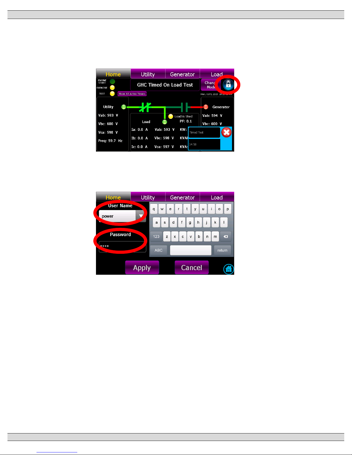
TSC 900 TRANSFER SWITCH CONTROLLER
PM 151 REV 5 16/04/19 Thomson Power Systems
58
5.2. USER LOGIN PROCEDURE
With the transfer switch energized, follow the procedure below to Login to the TSC 900
controller:
• Navigate to the “Home” Page below and select the Locked Icon as shown below
• The Login entry screen automatically pops-up as shown below. Select User Name drop
down box and choose desired group, then type in password, then select “Apply” button.
Note: Initial Factory Default Password is “pass”
• A Login confirmation screen will pop-up if attempt was successful. Select Return to go
back to the Home Page.
Page 67
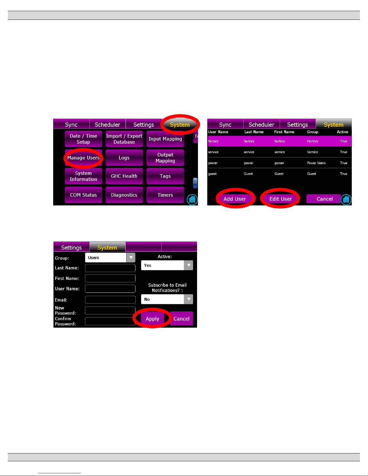
TSC 900 TRANSFER SWITCH CONTROLLER
PM 151 REV 5 16/04/19 Thomson Power Systems
59
5.3. ADMINISTRATOR PASSWORD MANAGEMENT PROCEDURE
With the transfer switch energized, follow the procedure below to add or edit a list of ATS
users.
• Navigate to the “System” Page and select “Manage Users” as shown below
• When the “Manager Users” button is pressed, the following pop-up screen will appear.
This page will indicate which existing users have been entered already and new users to
be added or existing users to be edited. Select desired action button (i.e. Add User or Edit
User)
• To Add a user, press “Add User” button and the following pop-up screen will appear. Complete
the information as listed, then press Apply to accept the change.
Page 68
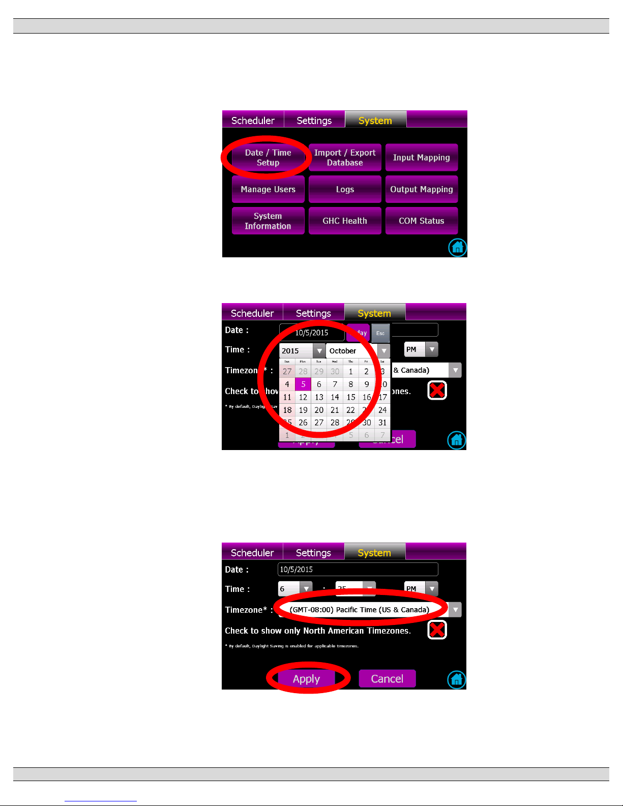
TSC 900 TRANSFER SWITCH CONTROLLER
PM 151 REV 5 16/04/19 Thomson Power Systems
60
5.4. SYSTEM TIME/DATE ADJUSTMENT
To adjust the TSC 900 controller’s internal time clock, follow the detailed procedure below.
• Navigate to SYSTEM screen and press TIME/DATE SETUP button as shown below.
• Select Date field and a calendar will automatically pop-up to allow selection of day, month
and year as shown below.
• Select Time fields and drop down lists will appear to allow selection of desired hour, minute
and AM/PM settings.
• Select Time zone field and a drop down list will appear to allow selection of desired time
zone. Note: To show only North American Time Zones, select check box as shown below
• Once correct time/date & time zone is entered, then use the Apply button to accept the
change.
Page 69
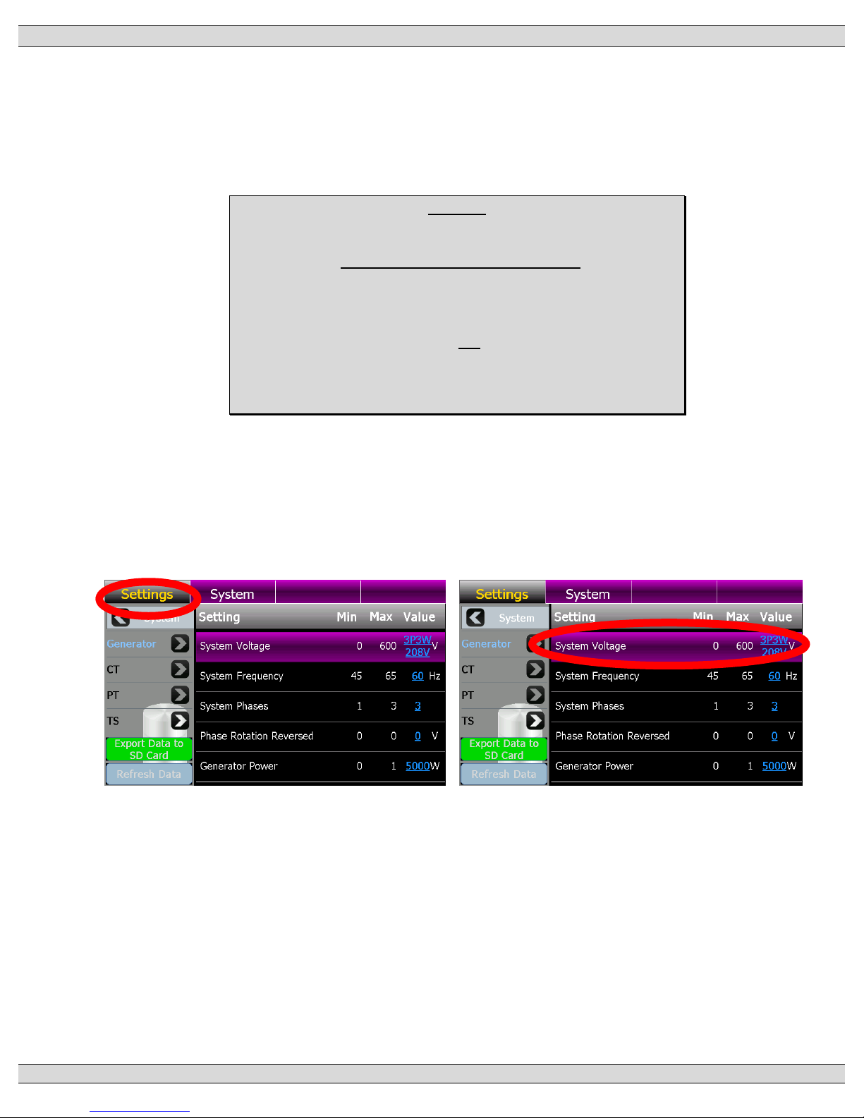
TSC 900 TRANSFER SWITCH CONTROLLER
PM 151 REV 5 16/04/19 Thomson Power Systems
61
5.5. VOLTAGE CHANGE PROCEDURE
To change system voltage on the TSC 900 controller, the transfer switch must be energized
to provide control power to the controller to allow software programming. If safe to do so,
energize Transfer Switch on either Utilty or Generator sources and follow the programming
procedure shown below.
NOTES:
1. The following instructions detail re-programming the TSC 900
controller only. Additional procedures are required to change the
voltage sensing transformer taps inside the ATS. Refer to
separate ATS model instructions.
2. The TSC 900 controller does not contain any voltage jumpers
on the printed circuit board. All voltage changes are done via
software programming only.
• Login to the TSC 900 with a level of “POWER” or “ADMIN” as described in Section 5.2.
Note: Initial Factory Default Password is “pass”
• Once successfully logged in, From the TSC 900 DISPLAY Home Page, navigate to the
“Settings” Page shown below and select “System Voltage” parameter as shown below.
2.
Page 70
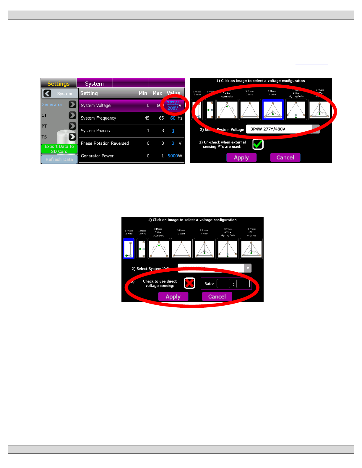
TSC 900 TRANSFER SWITCH CONTROLLER
PM 151 REV 5 16/04/19 Thomson Power Systems
62
• On the System Voltage Row, select the type of system configuration (i.e. wye or delta) per
voltage diagrams provided, then select the applicable voltage from the drop down list as
shown below. If the desired voltage is not listed, select “Custom” and enter the Line to Line
System voltage. For a complete list of voltage configurations supported, refer to Section 2.4
• If utilizing external voltage sensing potential transformers, un-check the identified PT box,
then enter the applicable PT primary and secondary winding voltages as shown below. The
controller will calculate the required PT ratio for the application.
• To confirm the change, press the “Apply” button.
Page 71
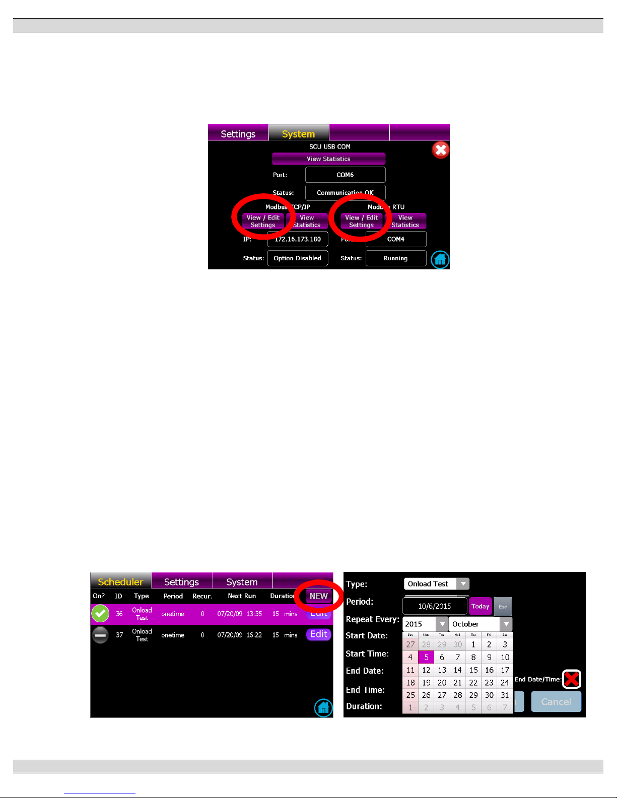
TSC 900 TRANSFER SWITCH CONTROLLER
PM 151 REV 5 16/04/19 Thomson Power Systems
63
5.6. REMOTE COMMUNICATION SETUP
To adjust the TSC 900 controller’s remote communication settings, navigate to the Systems
Page, then select the Communication Status page. The following page will be displayed. To
change settings, select the required “View / Edit Settings” buttons as indicated below.
For further information on remote com settings and/or Modbus data addressing, refer to
separate product manual PM0152 “TSC 900 MODBUS COMMUNICATION MANUAL”.
5.7. EXERCISE TIMER SETUP
The TSC 900 controller has a built-in calendar based programmable exercise timer. The
exercise timer is fully programmable for, day of week, time of day, duration of the test and type
of test mode (i.e. On Load or Off Load). The exercise timer utilizes the TSC 900 GHC internal
real-time clock for referencing all timing functions. The GHC real-time clock utilizes a battery
back-up power source to retain correct time/date settings during short duration utility power
failures.
5.7.1. ADDING NEW EXERCISE SCHEDULE EVENT
• From the GHC Home Page, navigate to the GHC “Scheduler” Page and select NEW
as shown below;
Page 72
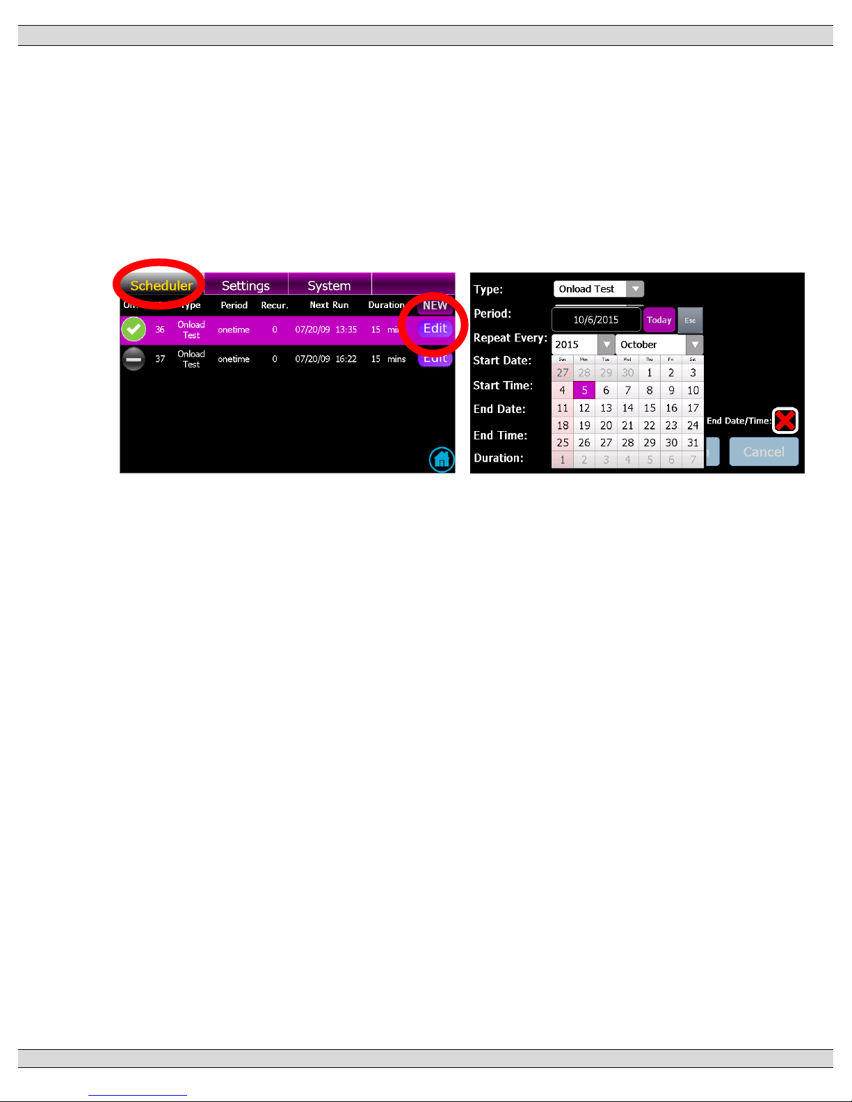
TSC 900 TRANSFER SWITCH CONTROLLER
PM 151 REV 5 16/04/19 Thomson Power Systems
64
• Once in the Scheduler Editor page, select desired Exercise type (on load or off load),
then select desired Exercise schedule (i.e. period, reoccurrence, start time, stop time,
end date, end time and exercise duration).
5.7.2. EDITING EXISTING EXERCISE SCHEDULE EVENT
• From the GHC Home Page, navigate to the GHC “Scheduler” Page, select desired
schedule (row) to be edited, then select EDIT button on the selected item as shown
below;
• Once in the Scheduler Editor page, select desired Exercise type (on load or off load),
then select desired Exercise schedule (i.e. period, reoccurrence, start time, stop time,
end date, end time and exercise duration).
Page 73
TSC 900 TRANSFER SWITCH CONTROLLER
PM 151 REV 5 16/04/19 Thomson Power Systems
65
5.8. PROGRAMMABLE DIGITAL INPUT MAPPING
All 16 Programmable inputs can be mapped to a number of different parameters to suit the
application. In addition, programmable inputs may be programmed with custom names to suit a
specific application. The TSC 900 is provided with factory programmed default settings based
upon the ATS configuration. Refer to the following sections for specific default program tables.
5.8.1. TS 870 STANDARD/SERVICE ENTRANCE INPUT DEFAULTS:
5.8.2. TS 870 DUAL SOURCE INPUT DEFAULTS:
Inputs GHC Descriptions SCU TAG Names
IP01
Remote Test - Utility Power Fail Simulate
test.req.remote.a
IP02
Remote Alarm Reset
ctl.reset.req
IP03
Service Disconnect Mode Activated
ctl.discon.req.a
IP04
Utility Power Switching Device (USD) Tripped
tip.switch.tripped.1
IP05
Generator Power Switching Device (GSD) Tripped
tip.switch.tripped.2
IP06
Transfer Control in Manual
ctl.man.req.a
IP07
Not mapped
IP08
Not mapped
IP09
Not mapped
IP10
Not mapped
IP11
Not mapped
IP12
Not mapped
IP13
Not mapped
IP14
Not mapped
IP15
Inhibit Transfer to Utility (Source 1)
ilk.xfr.tosrc.1.inhibit
IP16 Inhibit Transfer to Generator (Source 2) ilk.xfr.tosrc.2.inhibit
Inputs GHC Descriptions SCU TAG Names
IP01
Remote Test - Source 1 Power Fail Simulate
test.req.remote.a
IP02
Remote Alarm Reset
ctl.reset.req
IP03
Service Disconnect Mode Activated
ctl.discon.req.a
IP04
SRC 1 Power Switching Device Tripped
tip.switch.tripped.1
IP05
SRC 2 Power Switching Device Tripped
tip.switch.tripped.2
IP06
Transfer Control in Manual
ctl.man.req.a
IP07
Not mapped
IP08
Not mapped
IP09
Not mapped
IP10
Not mapped
IP11
Not mapped
IP12
Not mapped
IP13
Source 1 Alarm Input
pfs.trouble.1
IP14
Source 2 Alarm Input
pfs.trouble.2
IP15
Source 1 Prime Unit Selected
pfs.req.1
IP16 Source 2 Prime Unit Selected pfs.req.2
Page 74
TSC 900 TRANSFER SWITCH CONTROLLER
PM 151 REV 5 16/04/19 Thomson Power Systems
66
5.8.3. TS 880 (ICS) STANDARD/SERVICE ENTRANCE INPUT DEFAULTS:
5.8.4. TS 880 (ICS) CLOSED TRANSITION INPUT DEFAULTS:
Inputs GHC Descriptions SCU TAG Names
IP01
Remote Test - Utility Power Fail Simulate
test.req.remote.a
IP02
Remote Alarm Reset
ctl.reset.req
IP03
Service Disconnect Mode Activated
ctl.discon.req.a
IP04
Utility Power Switching Device (USD) Tripped
tip.switch.tripped.1
IP05
Not mapped
IP06
Transfer Control in Manual (External Control
ctl.man.req.a
IP07
Not mapped
IP08
Utility Power Switching Device (USD) Open*
tip.switch.opened.1
IP09
Generator Power Switching Device (GSD) Open*
tip.switch.opened.2
IP10
Not mapped
IP11
Not mapped
IP12
Not mapped
IP13
Not mapped
IP14
Not mapped
IP15
Closed Transition Extended Parallel
ilk.xfr.tosrc.1.inhibit
IP16 Inhibit Transfer to Generator (Source 2) ilk.xfr.tosrc.2.inhibit
Inputs GHC Descriptions SCU TAG Names
IP01
Remote Test - Utility Power Fail Simulate
test.req.remote.a
IP02
Remote Alarm Reset
ctl.reset.req
IP03
Service Disconnect Mode Activated
ctl.discon.req.a
IP04
Utility Power Switching Device (USD) Tripped
tip.switch.tripped.1
IP05
Closed Transition Extended Parallel
ilk.xfr.parallel.permit
IP06
Transfer Control in Manual
ctl.man.req.a
IP07
Transfer Control in Closed Transition Mode
ilk.xfr.closed.permit
IP08
Utility Power Switching Device (USD) Open*
tip.switch.opened.1
IP09
Generator Power Switching Device (GSD) Open*
tip.switch.opened.2
IP10
Closed Transition Inhibit (Utility Protection Relay
ilk.xfr.closed.inhibit.prot
IP11
Gen (Source 2) Unloaded
ctl.unloaded.2
IP12
Utility (Source 1) Unloaded
ctl.unloaded.1
IP13
In-Sync Transfer Permit
ctl.synced.ext
IP14
Closed Transition Soft-Load
ilk.xfr.soft.permit
IP15
Inhibit Transfer to Utility (Source 1)
ilk.xfr.tosrc.1.inhibit
IP16 Inhibit Transfer to Generator (Source 2) ilk.xfr.tosrc.2.inhibit
Page 75
TSC 900 TRANSFER SWITCH CONTROLLER
PM 151 REV 5 16/04/19 Thomson Power Systems
67
5.8.5. PROGRAMMABLE INPUT FUNCTION LIST
The following input functions can be mapped to any programmable input. Note: inputs
can be programmed only once (i.e. same input type cannot be utilized on multiple
programmable inputs).
TagName TagDescription
ctl.discon.req.a Service Disconnect Mode Activated
ctl.inputs.i01 User Def Input 1
ctl.inputs.i02 User Def Input 2
ctl.inputs.i03 User Def Input 3
ctl.inputs.i04 User Def Input 4
ctl.inputs.i05 User Def Input 5
ctl.inputs.i06 User Def Input 6
ctl.inputs.i07 User Def Input 7
ctl.inputs.i08 User Def Input 8
ctl.inputs.i09 User Def Input 9
ctl.inputs.i10 User Def Input 10
ctl.inputs.i11 User Def Input 11
ctl.inputs.i12 User Def Input 12
ctl.inputs.i13 User Def Input 13
ctl.inputs.i14 User Def Input 14
ctl.inputs.i15 User Def Input 15
ctl.inputs.i16 User Def Input 16
ctl.man.req.a Transfer Control in Manual
ctl.off.req.a Non-Auto Off Request (Remote)
ctl.reset.req Reset Alarm Request
ctl.rtn.req.a Manual Return Request (Remote)
ctl.start.1.remote.a Off Load Test Request (GEN 1)
ctl.start.2.remote.a Off Load Test Request (Remote)
ctl.stdby.req Standby Request
ctl.sync.ext.fail Ext. Sync Check Failed
ctl.synced.ext Ext. Sync Check Permitted
ctl.unfail.req.a Unfail Request (Remote)
ctl.unhalt.req.a Unhalt Request (Remote)
ctl.unloaded.1 SRC 1 Unload Permitted
ctl.unloaded.2 SRC 2 Unload Permitted
Page 76
TSC 900 TRANSFER SWITCH CONTROLLER
PM 151 REV 5 16/04/19 Thomson Power Systems
68
TagName TagDescription
ilk.xfr.closed.inhibit Closed Transition Mode Inhibit
ilk.xfr.closed.inhibit.prot Closed Transition Inhibit Prot
ilk.xfr.closed.permit Closed Transition Mode Permit
ilk.xfr.inphase.inhibit In-Phase Transfer Inhibit
ilk.xfr.inphase.permit In-Phase Transfer Permit
ilk.xfr.ndtbypass.inhibit NDT Bypass Inhibit
ilk.xfr.ndtbypass.permit NDT Bypass Permit
ilk.xfr.parallel.inhibit Enable Extended Parallel Transfer Inhibit (CTTS Model 4)
ilk.xfr.parallel.permit Enable Extended Parallel Transfer Permit (CTTS Model 4)
ilk.xfr.revert.inhibit Revert to Open Transition Inhibited
ilk.xfr.revert.permit Revert to Open Transition Permited
ilk.xfr.soft.inhibit Soft Load ATS Mode Inhibit
ilk.xfr.soft.permit Soft Load ATS Mode Permit
ilk.xfr.tosrc.1.inhibit Inhibit Transfer to SRC 1
ilk.xfr.tosrc.1.permit Permit Transfer to SRC 1
ilk.xfr.tosrc.2.inhibit Inhibit Transfer to SRC 2
ilk.xfr.tosrc.2.permit Permit Transfer to SRC 2
pfs.pause Pause Automatic Source Alternation
pfs.req.1 SRC 1 Prime Unit Selected
pfs.req.2 SRC 2 Prime Unit Selected
pfs.trouble.1 SRC 1 Alarm Input
pfs.trouble.2 SRC 2 Alarm Input
test.req.remote.a Remote Test Request
tip.switch.opened.1 SRC 1 Power Switching Device Opened
tip.switch.opened.2 SRC 2 Power Switching Device Opened
tip.switch.tripped.1 SRC 1 Power Switch. Device Tripped
tip.switch.tripped.2 SRC 2 Power Switch. Device Tripped
tmr.clr.remote.a Clear Timers Request (Remote)
Page 77
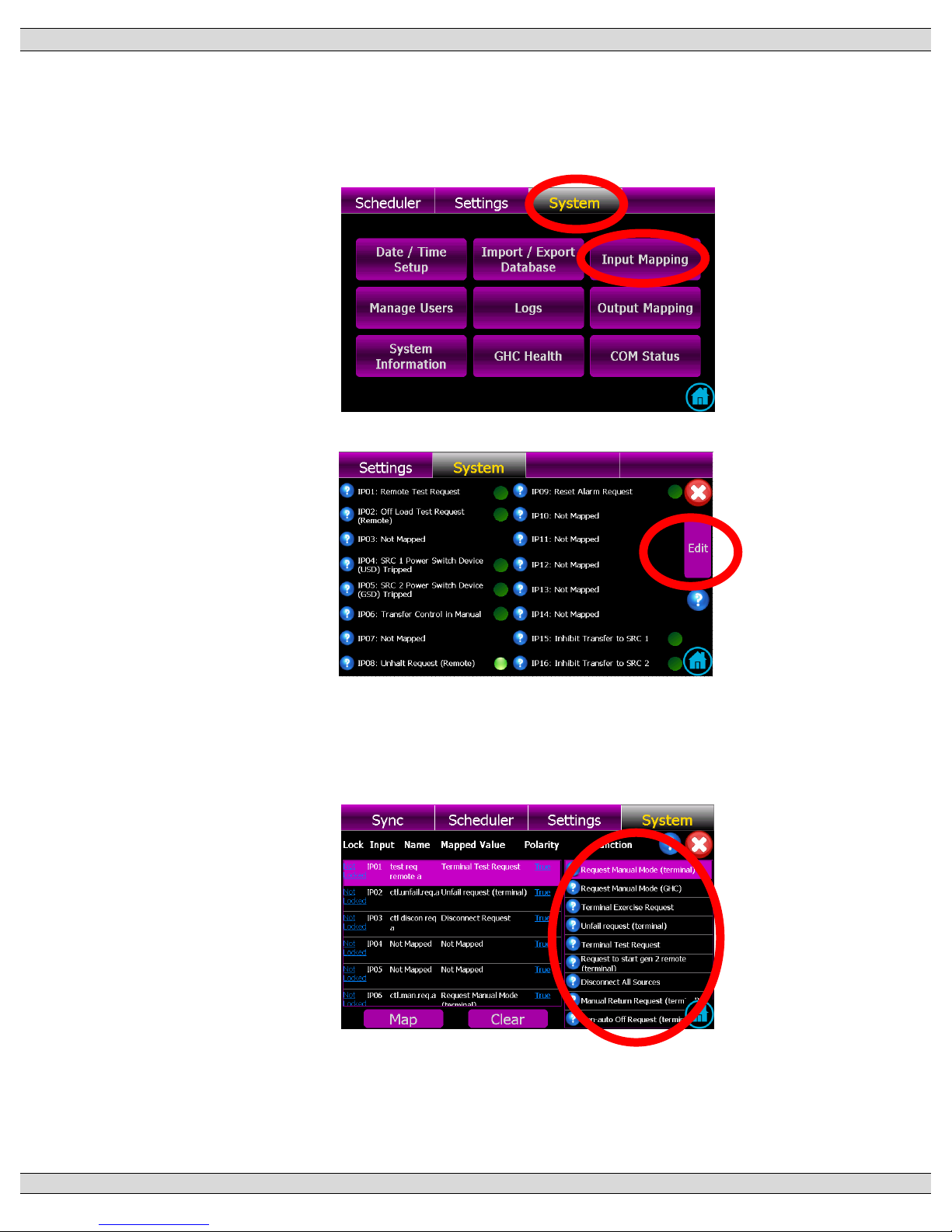
TSC 900 TRANSFER SWITCH CONTROLLER
PM 151 REV 5 16/04/19 Thomson Power Systems
69
5.8.6. PROGRAMMABLE INPUT FUNCTION MAPPING
To edit programmable inputs, follow the procedure listed below:
a) From the GHC Home Page, navigate to the “SYSTEM” Page and select “Input
Mapping” as shown below:
b) With the Input Mapping page displayed, press the EDIT button as shown below:
c) With the Input Mapping page displayed, select the desired programmable input # (row)
to be edited, then select the desired function for mapping (scroll up or down to navigate
to desired function):
d) Once desired function is selected, press Map button to accept the change.
Page 78
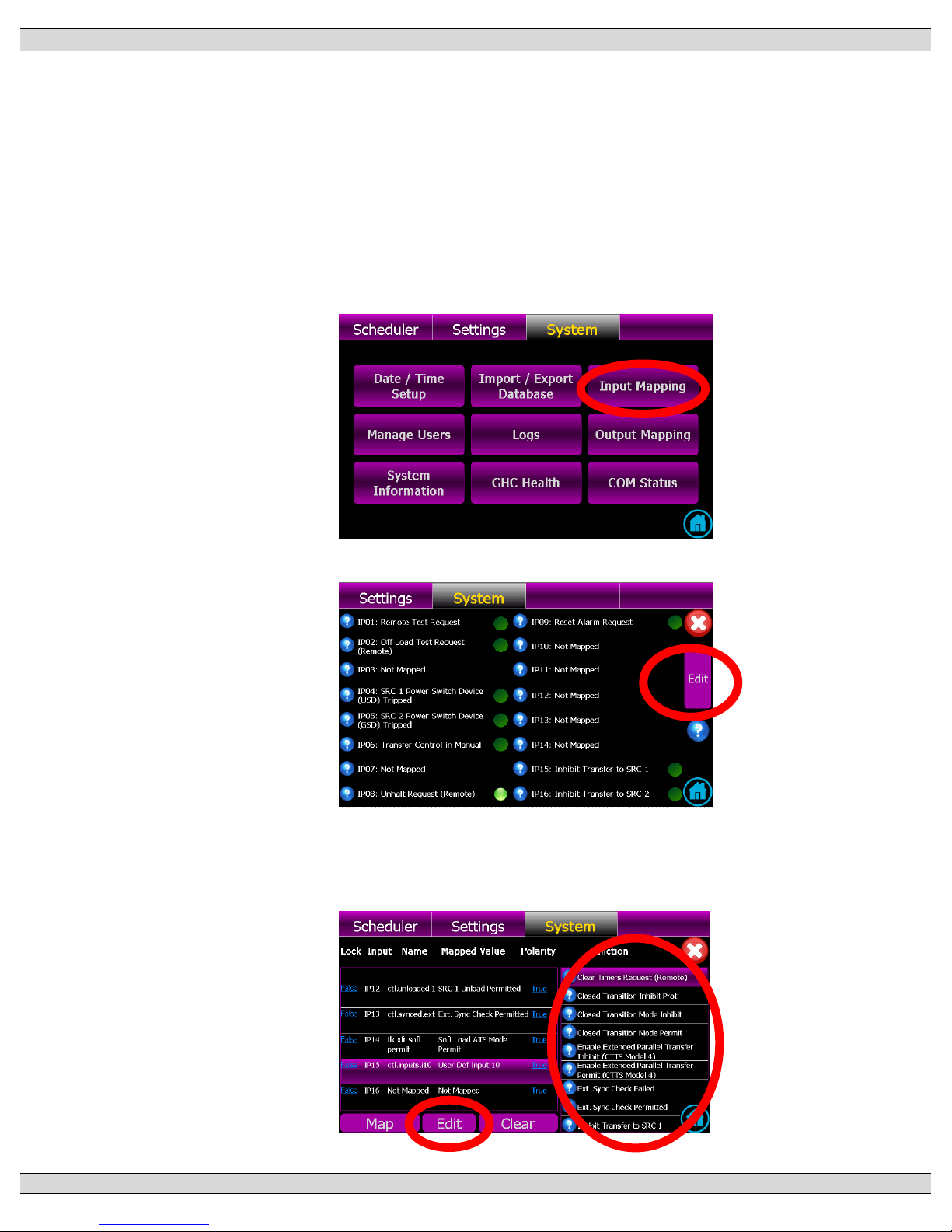
TSC 900 TRANSFER SWITCH CONTROLLER
PM 151 REV 5 16/04/19 Thomson Power Systems
70
e) To return to the input mapping page once the change is accepted, press red X icon
on the screen.
5.8.7. PROGRAMMABLE INPUT USER DEFINED CUSTOM NAME MAPPING
Up to 16 Programmable inputs may be programmed with custom names to suit specific
applications (e.g. Low Fuel Level Alarm). To edit or add custom names to a
programmable input, follow the procedure listed below:
a) From the GHC Home Page, navigate to the “SYSTEM” Page and select “Input
Mapping” as shown below:
b) With the Input Mapping page displayed, press the EDIT button as shown below:
c) With the Input Mapping page displayed, select the desired programmable input # (row)
to be edited, then select one of the available USER DEFINED 1-16 functions listed on
the right-hand side of the screen. Once selected, use the “Edit” button as shown below.
Page 79
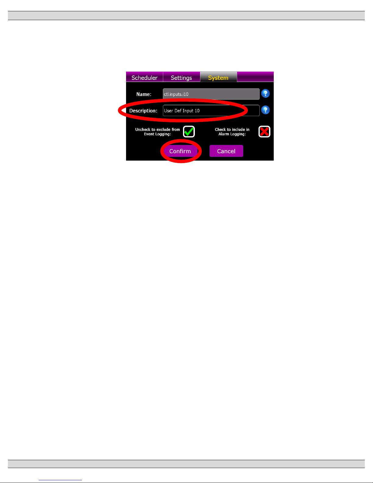
TSC 900 TRANSFER SWITCH CONTROLLER
PM 151 REV 5 16/04/19 Thomson Power Systems
71
d) The following Edit input screen will pop-up to allow entering a custom name into the
description field. Once the custom name is entered, you can select if the programmable
input is to be included or excluded from the TSC 900 alarms feature. Select the required
check box as shown. Once complete, press the “Confirm” but to complete the entry.
Page 80
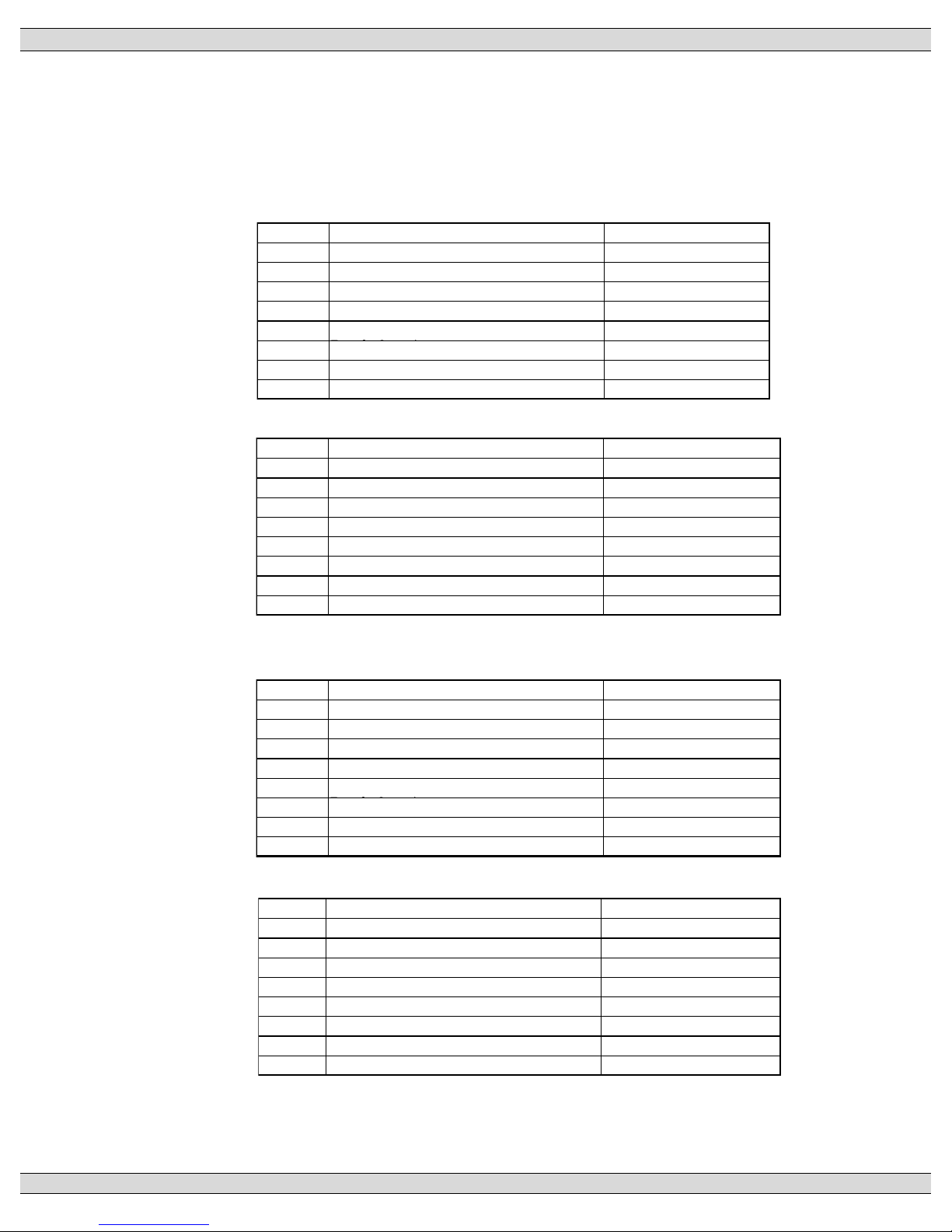
TSC 900 TRANSFER SWITCH CONTROLLER
PM 151 REV 5 16/04/19 Thomson Power Systems
72
5.9. PROGRAMMABLE OUTPUT MAPPING
All 8 Programmable outputs can be mapped to a number of different parameters to suit the
application. The TSC 900 is provided with factory programmed default settings based upon the
ATS configuration. Refer to the following sections for specific default program tables.
5.9.1. TS 870 STANDARD/SERVICE ENTRANCE OUTPUT DEFAULTS:
5.9.2. TS 870 DUAL SOURCE OUTPUT DEFAULTS:
5.9.3. TS 880 (ICS) STANDARD/SERVICE ENTRANCE OUTPUT
DEFAULTS:
5.9.4. TS 880 (ICS) CLOSED TRANSITION OUTPUT DEFAULTS:
Outputs GHC Descriptions SCU TAG Names
OP01
Load on Source 1
ctl.onsrc.1
OP02
Load on Source 1
ctl.onsrc.1
OP03
Load on Source 2
ctl.onsrc.2
OP04
Load on Source 2
ctl.onsrc.2
OP05
Load Disconnect Contact (LDC) (Pre/Post
ctl.ldc
OP06
Transfer Fail Alarm
alm.any
OP07
ATS Not in Auto
!ctl.auto
OP08
Source 1 Power Fail (UPF) trp.src.1.any
Outputs GHC Descriptions SCU TAG Names
OP01
Load on Utility
ctl.onsrc.1
OP02
Load on Utility
ctl.onsrc.1
OP03
Load on Generator
ctl.onsrc.2
OP04
Load on Generator
ctl.onsrc.2
OP05
Load Disconnect Contact (LDC) (Pre/Post
ctl.ldc
OP06
Transfer Fail Alarm
alm.any
OP07
ATS Not in Auto
!ctl.auto
OP08
Utility Power Fail (UPF) trp.src.1.any
Outputs GHC Descriptions SCU TAG Names
OP01
Load on Utility
ctl.onsrc.1
OP02
Load on Utility
ctl.onsrc.1
OP03
Load on Generator
ctl.onsrc.2
OP04
Load on Generator
alm.any
OP05
Load Disconnect Contact (LDC) (Pre/Post
ctl.ldc
OP06
Not Mapped
OP07
Not Mapped
OP08
Not Mapped
Outputs GHC Descriptions SCU TAG Names
OP01
Load on Utility
ctl.onsrc.1
OP02
Load on Utility
ctl.onsrc.1
OP03
Load on Generator
ctl.onsrc.2
OP04
Transfer Fail Alarm
alm.any
OP05
Load Disconnect Contact (LDC) (Pre/Post
ctl.ldc
OP06
Automatic Sync Initiate
ctl.sync.ext
OP07
Generator (Source 2) Unload
ctl.unload.2
OP08
Utility (Source 1) Unload clt.unload.1
Page 81
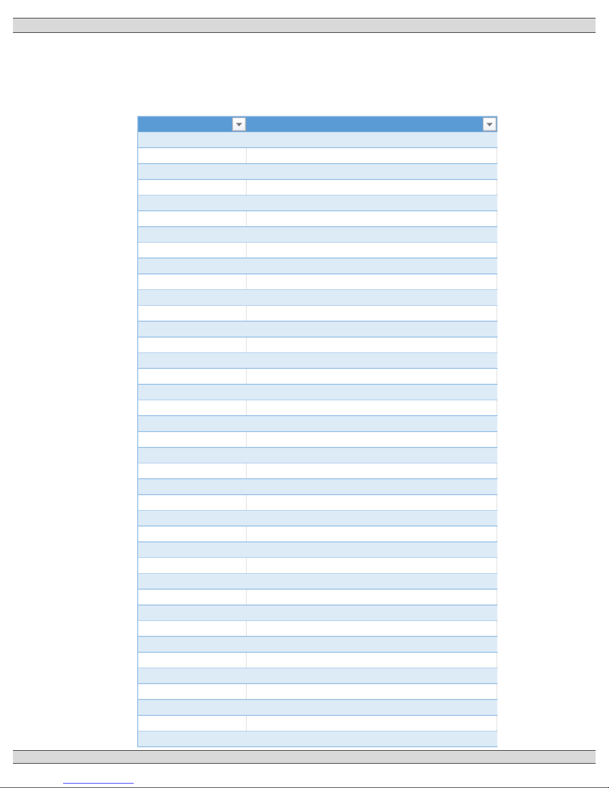
TSC 900 TRANSFER SWITCH CONTROLLER
PM 151 REV 5 16/04/19 Thomson Power Systems
73
5.9.5. PROGRAMMABLE OUTPUT FUNCTION LIST
The following output functions can be mapped to any programmable output. Note:
outputs can be programmed multiple times to provide additional output contacts of same
type.
TagName TagDescription
alm.any ATS Common Fail Alarm
alm.gen.failtorun.1 Gen 1 Failed While Running
alm.gen.failtorun.2 Gen 2 Failed While Running
alm.gen.muststart.1 Gen 1 Standby Source Failed to Start
alm.gen.muststart.2 Gen 2 Standby Source Failed to Start
alm.onsrc.1 Src 1 Fail to Transfer Common Alarm
alm.onsrc.2 Src 2 Fail to Transfer Common Alarm
alm.xfr.detect.1 Load on Src 1 Limit Sw/Aux Contact Failure
alm.xfr.detect.2 Load on Src 2 Limit Sw/Aux Contact Failure
alm.xfr.fail ATS Fail to Transfer Common Alarm
alm.xfr.mech.1 Src 1 Fail to Open/Close Alarm
alm.xfr.mech.2 Src 2 Fail to Open/Close Alarm
alm.xfr.sync Fail to Drift Sync Timeout
alm.xfr.sync.ext Fail to Externally Auto Sync Timeout
alm.xfr.trip.1 Loss of Load Voltage - Src 1 Contacts Open
alm.xfr.trip.2 Loss of Load Voltage - Src 2 Contacts Open
alm.xfr.unload.1 Src 1 Fail to Unload
alm.xfr.unload.2 Src 2 Fail to Unload
ctl.auto Controller in Auto
ctl.breaker.1.trip SRC 1 Trip Breaker
ctl.breaker.2.trip SRC 2 Trip Breaker
ctl.discon.req.a Service Disconnect Mode Activated
ctl.discon.req.b Disconnect Request (GHC)
ctl.disconnected Service Entrance Disc. Init
ctl.goto.discon Disconnect All Sources
ctl.goto.man De-Energize All Sources
ctl.halted System Halted
ctl.ldc Load Disconnect Contact (Pre/Post Transfer)
ctl.ldc.post Load Post-Disconnect
ctl.ldc.pre Load Pre-Disconnect
ctl.manual Control Manual
ctl.off Control Off
ctl.off.req.a Non-Auto Off Request (Remote)
ctl.off.req.b Non-Auto Off Request (GHC)
ctl.onsrc Load on Either Source
ctl.onsrc.1 Load on SRC 1
ctl.onsrc.2 Load on SRC 2
ctl.outputs.o01 User Def Output 1
ctl.outputs.o02 User Def Output 2
Page 82

TSC 900 TRANSFER SWITCH CONTROLLER
PM 151 REV 5 16/04/19 Thomson Power Systems
74
TagName TagDescription
ctl.outputs.o03 User Def Output 3
ctl.outputs.o04 User Def Output 4
ctl.outputs.o05 User Def Output 5
ctl.outputs.o06 User Def Output 6
ctl.outputs.o07 User Def Output 7
ctl.outputs.o08 User Def Output 8
ctl.reset.req Reset Alarm Request
ctl.rtn.req.a Manual Return Request (Remote)
ctl.rtn.req.b Manual Return Request (GHC)
ctl.shed Load is Shed
ctl.src.1.avail SRC 1 Available
ctl.src.2.avail SRC 2 Available
ctl.start.2.remote.a Off Load Test Request (Remote)
ctl.start.2.remote.b Off Load Test Request (GHC)
ctl.stdby.req Standby Request
ctl.sync.ext Auto Sync Initiate
ctl.sync.ext.fail Ext. Sync Check Failed
ctl.synced.ext Ext. Sync Check Permitted
ctl.transferring Control Transferring
ctl.underway Transfer Underway
ctl.unload.1 SRC 1 Unload Initiate
ctl.unload.2 SRC 2 Unload Initiate
ctl.unloaded.1 SRC 1 Unload Permitted
ctl.unloaded.2 SRC 2 Unload Permitted
ctl.waiting Wait for Sync
ena.xfr.closed Closed Transfer (Model 3/4)
ena.xfr.inphase In-Phase Transfer (Model X)
ena.xfr.ndtbypass Neutral delay timer bypass
ena.xfr.parallel Enable Extended Parallel Transfer (CTTS Model 4)
ena.xfr.revert Revert to Open Transfer
ena.xfr.soft Enable Soft Load Transfer (CTTS Model 4)
ena.xfr.tosrc.1 Enable Transfer to SRC 1
ena.xfr.tosrc.2 Enable Transfer to SRC 2
exr.active Exercise Active
exr.active.offload Exercise Active Offload
exr.active.onload Exercise Active Onload
exr.req.local Local Exercise Request
exr.req.remote.a Terminal Exercise Request
exr.req.remote.man Manual Exercise Request (GHC)
ilk.xfr.tosrc.1.inhibit Inhibit Transfer to SRC 1
Page 83

TSC 900 TRANSFER SWITCH CONTROLLER
PM 151 REV 5 16/04/19 Thomson Power Systems
75
TagName TagDescription
ilk.xfr.tosrc.1.permit Permit Transfer to SRC 1
ilk.xfr.tosrc.2.permit Permit Transfer to SRC 2
sync.xfr.trigger Sources are In-Phase
test.active Test Active
test.active.local Local Test Active
test.active.remote Remote Test Active
test.req.remote.a Remote Test Request
test.req.remote.b GHC Test Request
tip.switch.onsrc.1 ATS on SRC 1
tip.switch.onsrc.2 ATS on SRC 2
tip.switch.opened.1 SRC 1 Power Switching Device Opened
tip.switch.opened.2 SRC 2 Power Switching Device Opened
tip.switch.tripped.1 SRC 1 Power Switch. Device Tripped
tip.switch.tripped.2 SRC 2 Power Switch. Device Tripped
tmr.rtn Return to Preferred Source
tmr.stdby.pref Wait for Preferred Source
tmr.util.rtn UTIL Return
top.start.2 Engine Start Request SRC 2
top.switch.bksrc.1 Breaker 1 to output
top.switch.bksrc.2 Breaker 2 to output
top.switch.tosrc.1 SRC 1 to output
top.switch.tosrc.2 SRC 2 to output
trp.load.volt.black Load Blackout Voltage
trp.shed.freq Load Shed Freq Active
trp.shed.power Load Shed kW Active
trp.src.1.any SRC 1 Power Fail
trp.src.1.freq.over SRC 1 Overfrequency
trp.src.1.freq.undr SRC 1 Underfrequency
trp.src.1.volt.over SRC 1 Overvoltage
trp.src.1.volt.reverse SRC 1 Voltage Rotation Reversed
trp.src.1.volt.unbal SRC 1 Unbalancedvoltage
trp.src.1.volt.undr SRC 1 Undervoltage
trp.src.2.any SRC 2 Power Fail
trp.src.2.freq.over SRC 2 Overfrequency
trp.src.2.freq.undr SRC 2 Underfrequency
trp.src.2.volt.over SRC 2 Overvoltage
trp.src.2.volt.reverse SRC 2 Voltage Rotation Reversed
trp.src.2.volt.unbal SRC 2 Unbalancedvoltage
trp.src.2.volt.undr SRC 2 Undervoltage
trp.sync.any Synchronization Out-of-Spec
Page 84
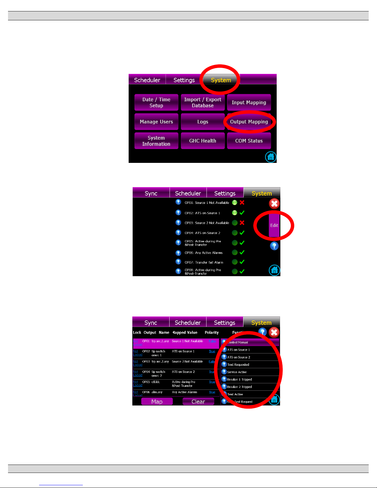
TSC 900 TRANSFER SWITCH CONTROLLER
PM 151 REV 5 16/04/19 Thomson Power Systems
76
5.9.6. PROGRAMMABLE OUTPUT FUNCTION MAPPING
The edit the programmable outputs, follow the procedure listed below:
a) From the GHC Home Page, navigate to the “SYSTEM” Page and select Output
Mapping as shown below
b) With the Output Mapping page displayed, press the EDIT button as shown below:
c) With the Output Mapping page displayed, select the desired programmable output #
(row) to be edited, then select the desired function for mapping (scroll up or down to
navigate to desired function):
d) Once desired function is selected, press Map button to accept the change.
e) To return to the output mapping page once the change is accepted, press red X icon
on the screen.
Page 85
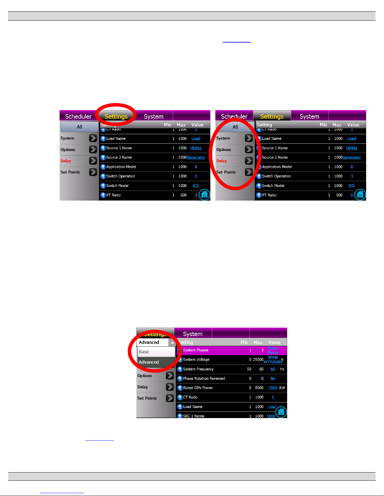
TSC 900 TRANSFER SWITCH CONTROLLER
PM 151 REV 5 16/04/19 Thomson Power Systems
77
5.10. SYSTEM SETTINGS
Note: For specific device settings and ranges, refer to Section 6 - Factory Default Programming.
The TSC 900 controller provides a flexible control system to allow specific operation for a wide
range of applications. To program settings, navigate to the “Settings” page as shown below.
Once on the Settings Page, select the group of Settings by adjusting the filter and scroll through
available list of functions as available.
System settings are organized into the following 3 main groups as selected by drop-down list
selection shown below:
• Basic - The Basic group contains the most commonly used settings to configure a
standard transfer switch.
• Advanced – Advanced settings group contains less commonly used features which
allow users to customize the operation of the transfer switch to suit the application.
• Factory - The Factory group of settings are only accessible through a Factory
password and allow the ATS to be configured for specific applications.
Refer to Section 6 for a complete list of all Settings and their associated groups.
Page 86

TSC 900 TRANSFER SWITCH CONTROLLER
PM 151 REV 5 16/04/19 Thomson Power Systems
78
5.10.1. SYSTEM PHASES
Set to match the power distribution system used on the automatic transfer switch (i.e.
either single phase or 3 phase system).
5.10.2. SYSTEM VOLTAGE
Set to nominal system voltage as expressed in “phase to phase” voltage. (E.g. A
347/600-volt system would be entered as “600”.) A drop down list of common voltages
appears when the blue underlined value is selected. Refer to Section 2.4 for a listing of
available AC system voltage sensing configurations possible with a TSC 900.
5.10.3. SYSTEM FREQUENCY
Set to nominal system frequency of either 50Hz or 60Hz.
5.10.4. PHASE ROTATION REVERSED
The Transfer switch is configured from the factory to operate on a normal A-B-C
(Positive) phase rotating system (i.e. Option Feature set for “NO”). This allows for correct
operation of voltage sensing and power metering option (if equipped) utilizing the TSC
900’s internal symmetrical component algorithms (i.e. positive/negative/zero sequence
components). If the system is to operate on a C-B-A (Reverse) phase rotating system,
set this feature to “YES”. Note: Automatic transfers between sources will be halted (i.e.
blocked) if both source phase rotations are not matched. Refer to Section 4.13 for further
operating information on Transfer Halt conditions.
5.10.5. RATED GENERATOR POWER
Set to match the 100% power rating of the connected Generator set in kilowatts. This
setting is utilized for the kW Load Shed set point calculations.
5.10.6. CT RATIO (CURRENT TRANSFORMER)
When load bus current transformers (CTs) are utilized in the ATS, set to value of the
specific ratio of the CT size being used (e.g. If using 400:5 rated CT’s, enter a value of
80).
5.10.7. PT RATIO (POTENTIAL TRANSFORMER)
For direct voltage sensing wiring connections from 208 to 600 volts, enter a value of
“1.0”. When potential transformers are utilized for voltage sensing, enter the transformer
ratio. (E.g. When using 600:120 potential transformers, enter a value of “5.0”). The ratio
is programmable in tenths to allow minor correction factors to be used for non-standard
potential transformer ratios.
Page 87

TSC 900 TRANSFER SWITCH CONTROLLER
PM 151 REV 5 16/04/19 Thomson Power Systems
79
5.10.8. LOAD NAME
The GHC Display can be configured to display a unique name in place of the text “Load”
as desired. When a new text name is entered, it will be utilized throughout the GHC
display in place of where the text “Load” was previously utilized.
5.10.9. SOURCE 1 (UTILITY) NAME
The GHC Display can be configured to display a unique name in place of the text “Source
1” (i.e. Utility) as desired. When a new text name is entered, it will be utilized throughout
the GHC display in place of where the text “Source 1” was previously utilized.
5.10.10. SOURCE 2 (GEN) NAME
The GHC Display can be configured to display a unique name in place of the text “Source
2” (i.e. Gen) as desired. When a new text name is entered, it will be utilized throughout
the GHC display in place of where the text “Source 2” was previously utilized.
5.10.11. APPLICATION MODEL
The GHC Display will display the ATS application model type it is configured to (i.e. STD,
SE, DS etc.). This is a “read-only” parameter and cannot be changed.
5.10.12. SWITCH OPERATION
The GHC Display will display the Switch Operation type it is configured to (i.e. Open
Transition, Closed Transition, Manually Operated, etc.). This is a “read-only” parameter
and cannot be changed.
5.10.13. SWITCH MODEL
The GHC Display will display the Switch Model type it is configured to (i.e. ATS
Mechanism Type S, T or ICS). This is a “read-only” parameter and cannot be changed.
5.11. OPTION SETTINGS
The TSC 900 has a number of options which can be set depending on type. To program Options,
navigate to the “Settings” page. Once on the Settings Page, select the “OPTIONS” on the left
side menu bar, and scroll through available list of functions as available.
5.11.1. SRC 2 (GEN) COMMIT TO TRANSFER
The TSC 900 transfer switch controller contains a “SRC 2 (GEN) COMMIT TO
TRANSFER” logic selection feature. This feature is user programmable and allows 2
different functional settings which are described below:
NO (DISABLED): The transfer switch will not commit to transfer to the generator
(SRC 2) after the engine start delay has expired, but will return to the utility supply
if immediately restored.
Page 88

TSC 900 TRANSFER SWITCH CONTROLLER
PM 151 REV 5 16/04/19 Thomson Power Systems
80
YES (ENABLED): The transfer switch will commit to transfer to the generator
(SRC 2) after the engine start delay has expired. “Selecting” the “ENABLED”
mode will prevent numerous engine starting and stopping sequences if the utility
supply is continuously fluctuating beyond the pre-set limits. The feature is
automatically cancelled after expiry of the Gen Commit to Transfer timer (5 mins
adjustable) should the generator fail to start.
5.11.2. ENABLE LOAD SHED ON UNDER FREQUENCY
When the Load Shed under frequency feature is enabled, the Load Shed control logic
will utilize load frequency threshold set points to determine when a Load Shed condition
is activated. Refer to Section 5.15 for programming the Load Shed frequency threshold
set points.
5.11.3. ENABLE LOAD SHED ON OVER POWER
When the Load Shed over power feature is enabled, the Load Shed control logic will
utilize load power (i.e. kW) threshold set points to determine when a Load Shed condition
is activated. Refer to Section 5.15 for programming the Load Shed power threshold set
points.
5.11.4. HALT OPERATION ON PHASE REVERSAL
When the Halt Operation on Reversed Phase Reversal is enabled, the ATS will not
transfer between sources unless both sources match the selected phase rotation (i.e.
both positive or negative rotation).
5.11.4.1. MANUAL SRC 1 (UTILITY) RETRANSFER CONTROL
The TSC 900 transfer switch controller contains a “MANUAL SRC 1 (UTILITY)
RETRANSFER CONTROL” feature, which allows an operator initiated re-transfer
sequence to occur when utility power has returned following a power failure. This feature
is user programmable and allows 2 different functional settings which are described
below:
NO (DISABLED): The transfer switch will automatically re-transfer back to the
utility supply if within nominal pre-programmed limits and following expiry of the
Utility Return Timer.
YES (ENABLED): The transfer switch will remain on the generator supply until
system operators manually initiate the re-transfer sequence by utilizing the
Manual Re-Transfer button on the GHC display home screen or utilizing a remote
input push button wired into a programmable input configured for manual
Page 89

TSC 900 TRANSFER SWITCH CONTROLLER
PM 151 REV 5 16/04/19 Thomson Power Systems
81
re-transfer. NOTE: The transfer switch will automatically re-transfer back to the
utility supply if the generator supply fails.
5.11.5. FORCE TRANSFER
The TSC 900 transfer switch controller contains a “FORCE TRANSFER” feature which
can be enabled to allow the ATS to automatically force a transfer to the alternate source
should an abnormal operating condition be detected with the ATS. The TSC 900
controller will detect abnormal conditions such as loss of ATS load voltage due to a
tripped power switching device or the transfer mechanism limit switch is not in the correct
state. The Force Transfer feature is user programmable and allows 2 different functional
settings as described below:
NO (DISABLED): Force transfer to alternate source is disabled in this mode. If
an abnormal operating condition is detected by the TSC 900 controller, a Transfer
Switch Fail Alarm will be posted on the GHC display. The TSC 900 controller will
keep the ATS mechanism in the current position and will take no further action.
The alarm condition may be reset utilizing the Reset button on the GHC Alarm
page.
YES (ENABLED): If an abnormal operating condition is detected by the TSC
900 controller, a Transfer Switch Fail Alarm will be posted on the GHC display
and the controller will immediately force a transfer to the alternate source if
available and within nominal limits. Note: “The transfer switch will remain on the
alternate source indefinitely until the “Transfer Fail” alarm condition is manually
reset on the GHC Alarm page”.
5.11.6. GHC SLEEP MODE TIMEOUT
The GHC display will automatically turn off and go in to a “sleep” mode to preserve
display operating lifetime. The sleep mode will be activated if a key press is not activated
within the pre-set time period. Touching the “Resume” button on the display will
automatically reactivate the GHC display screen to full brilliance.
5.11.7. LOAD POWER METERING
If the ATS was purchased with the LPM (Load Power Metering) Option, the power
metering can be enabled for display on the GHC by setting the value to YES.
5.11.8. MODBUS RTU
If the ATS was purchased with the Modbus serial (RTU) remote communication Option,
the com port on the GHC can be enabled by setting the value to YES.
Page 90

TSC 900 TRANSFER SWITCH CONTROLLER
PM 151 REV 5 16/04/19 Thomson Power Systems
82
5.11.9. MODBUS TCP/IP
If the ATS was purchased with the Modbus TCP/IP Ethernet remote communication
Option, the com port on the GHC can be enabled by setting the value to YES.
5.11.10. ENABLE SECURITY BYPASS
When the security bypass feature is enabled, it allows the ATS to be operated without a
security login. The TSC 900 is supplied from the factory with this feature enabled to allow
initial ATS operation during commissioning without the need for a security login. It is
recommended to disable this feature once the ATS is turned over to the end user so that
desired security passwords can be used. To enable the security bypass feature set the
value to YES.
5.11.11. ENABLE NEUTRAL DELAY BYPASS
The TSC 900 transfer switch controller contains “NEUTRAL DELAY BYPASS” logic,
which allows a shorter neutral delay timer period during transfer if the load bus voltage
falls to safe levels before the transfer sequence is completed. This feature is user
programmable and allows 2 different functional settings which are described below:
NO (DISABLED): The transfer switch neutral delay period will operate as per
the Neutral Delay Timer setting.
YES (ENABLED): The transfer switch neutral delay period will be bypassed if
the load bus voltage falls to safe levels before the transfer sequence is
completed.
Note: the neutral delay timer will be bypassed in either “Enabled” or “Disabled” modes
should the originating source voltage be in a de-energized (i.e. blackout) state prior to
transfer.
5.11.12. ENABLE TRANSFERS TO SRC 1 (UTILITY)
The TSC 900 transfer switch controller contains “ENABLE TRANSFERS TO UTILITY”
logic. This feature is user programmable and allows 2 different functional settings which
are described below:
NO (DISABLED): The transfer switch will be inhibited from transferring to the
Utility position.
YES (ENABLED): The transfer switch will be permitted to transfer to the Utility
position.
Page 91

TSC 900 TRANSFER SWITCH CONTROLLER
PM 151 REV 5 16/04/19 Thomson Power Systems
83
5.11.13. ENABLE TRANSFERS TO SRC 2 (GENERATOR)
The TSC 900 transfer switch controller contains “ENABLE TRANSFERS TO GEN” logic.
This feature is user programmable and allows 2 different functional settings which are
described below:
NO (DISABLED): The transfer switch will be inhibited from transferring to the
Generator position.
YES (ENABLED): The transfer switch will be permitted to transfer to the
Generator position.
5.11.14. ENABLE FAIL TO AUTO SYNC ALARM
When the ATS is ordered with a Closed Transition option (i.e. ATS Model Code Digit #13
“Operation Type” 3 or 4), and an external synchronizer is supplied, a fail to auto sync
alarm feature is available. When set to “YES” (i.e. enabled), it will post an alarm should
the sources fail to auto synchronize after expiry of the Fail to Auto Sync timer (i.e.
programmable per Section 5.16.2). The alarm will also activate the common TSC 900
"Transfer Fail" alarm output.
5.11.15. ENABLE HALT TRANSFER ON FAIL TO EXTERNAL SYNC
CHECK
The TSC 900 transfer switch controller contains a “HALT TRANSFER ON FAIL TO
EXTERNAL SYNC CHECK” logic selection feature. This feature is user programmable
and controls how the external automatic synchronizer initiate output is controlled.
NO (DISABLED): The Automatic Sync Initiate Output will stay energized to
continue an auto synchronizing operation irrespective if the “Fail to Auto Sync”
timer expires or not.
YES (ENABLED): The Automatic Sync Initiate Output will be de-energized upon
expiry of the “Fail to Auto Sync” time delay setting to halt further auto sync
operation.
5.11.16. ENABLE CLOSED TRANSITION TRANSFER (CTTS MODEL 3 &
4)
When the ATS is ordered with a Closed Transition Transfer option (i.e. ATS Model Code
Digit #13 “Operation Type” 3 or 4) the ATS can be selected for closed transition
operation. When the option is set to YES, the ATS will operate in a Closed Transition
transfer sequence dependent upon if both sources are available and the specific setting
of the GHC Home Page or via external control switch (if fitted). Three operation mode
settings are provided as follows:
Page 92

TSC 900 TRANSFER SWITCH CONTROLLER
PM 151 REV 5 16/04/19 Thomson Power Systems
84
• Fast Transfer: The two sources will be permitted to stay in parallel for a maximum
of 100 milliseconds only. Note: the ATS will automatically revert to open transition
transfer mode should only 1 source of power be available at time of transfer.
• Soft-Load: The two sources will be permitted to stay in parallel for a maximum of 10
seconds only to allow loads to be ramped between the sources by an external
controller Note: the ATS will automatically revert to open transition transfer mode
should only 1 source of power be available at time of transfer.
• Extended Parallel: Under normal operation, the two sources will be permitted to stay
in parallel continuously following a closed transition transfer operation. Note: the ATS
will automatically revert to open transition transfer mode should only 1 source of
power be available at time of transfer.
When the option is set to NO, the ATS will only operate in Open Transition transfer mode,
irrespective of GHC Home Page or via external control switch settings.
5.11.17. REVERT TO OPEN TRANSITION
For transfer switches equipped with closed transition transfer feature, the TSC 900
controller contains “REVERT to OPEN TRANSITION” logic. This logic allows the user to
select how the ATS operates should the closed transition transfer operation fail to
achieve an “in-sync” condition. This feature is user programmable and allows 2 different
functional settings which as described below:
NO (DISABLED): The ATS will not automatically revert to open-transition
transfer should the closed transition transfer operation fail to achieve an “in-sync”
condition. The ATS will remain in its last position in an alarmed state. If the alarm
is reset, the ATS will re-attempt a closed transition transfer operation sequence.
YES (ENABLED): The ATS will automatically revert to open-transition transfer
should the closed transition transfer operation fail to achieve an “in-sync”
condition for the allowed “in-sync wait” time delay period.
5.11.18. ENABLE FAIL TO UNLOAD ALARM (CTTS MODEL 4)
When the ATS is ordered with a Closed Transition soft-load option (i.e. ATS Model Code
Digit #13 “Operation Type” 4), a fail to unload alarm feature is available. When feature is
set to “Yes”, the TSC 900 controller will monitor the status of programmable inputs
configured for Utility unloaded (DI-12) and Generator unloaded (DI-13). When enabled,
it will post an alarm when the selected source fails to unload after expiry of the Fail to
Unload timer (programmable per Section 5.16.3) following a soft-load power transfer.
The alarm will also activate the common TSC 900 "Transfer Fail" alarm output.
Page 93

TSC 900 TRANSFER SWITCH CONTROLLER
PM 151 REV 5 16/04/19 Thomson Power Systems
85
5.11.19. ENABLE EXTENDED PARALLEL MODE (CTTS MODEL 4)
When the ATS is ordered with a Closed Transition soft-load option (i.e. ATS Model Code
Digit #13 “Operation Type” 4), the ATS can be operated in Extended Parallel mode.
NO (DISABLED): The transfer switch will be inhibited from operating in
Extended Parallel mode.
YES (ENABLED): The transfer switch will be permitted to operate in Extended
Parallel mode provided the Option is set for YES or designated programmable
input (i.e. default input IP05) is activated and both power sources are available
at time of desired operation. Note: the ATS will automatically revert to open
transition transfer mode should only 1 source of power be available at time of
transfer.
5.11.20. ENABLE SOFT-LOAD TRANSFER (CTTS MODEL 4)
When the ATS is ordered with a Closed Transition soft-load option (i.e. ATS Model Code
Digit #13 “Operation Type” 4), the ATS can be operated in Soft-Load mode.
NO (DISABLED): The transfer switch will be inhibited from operating in SoftLoad mode and will operate in either Open transition or Closed Transition Fast
transfer modes.
YES (ENABLED): The transfer switch will be permitted to operate in Soft-Load
closed transition mode provided the Option is set for YES or designated
programmable input (i.e. default input IP14) is activated and both power sources
are available at time of desired operation. Note: the ATS will automatically revert
to open transition transfer mode should only 1 source of power be available at
time of transfer.
5.11.21. ENABLE START OF MULTIPLE GENS WHEN RESUMING
FROM STANDBY
When the ATS is ordered with a Dual Standby Generator (DSG) option, a control feature
is provided to selection if one or both generators are to start when signaled during a
utility power failure condition from the Master ATS.
NO (DISABLED): Only the “Preferred” selected Generator will be signaled to
start from the Master ATS during a utility power failure condition.
YES (ENABLED): Both “Preferred” and “Standby” generator sets will be signaled
to start from the Master ATS during a utility power failure condition.
Page 94

TSC 900 TRANSFER SWITCH CONTROLLER
PM 151 REV 5 16/04/19 Thomson Power Systems
86
5.11.22. PREFERRED SOURCE ALTERNATION INTERVAL
When the ATS is ordered with a Dual Source option, a control feature is provided to allow
automatic changing of “Preferred” sources to balance operating hours. The feature
allows a programmable time interval between 1 - 672 hours. Note: This control feature
is only operational when the “Preferred” source selector is in the “AUTO” position. Refer
to Section 4.7.1 for further details on Dual Source Operation.
5.11.23. TRIP UTILITY (SRC 1) WHEN CLOSED TRANSITION INHIBIT
ACTIVATED
When the ATS is ordered with a Closed Transition option (i.e. ATS Model Code Digit #13
“Operation Type” 3 or 4), a control feature is provided which will trip open the selected
source power switching device should an inhibit operation signal be activated by an
external Utility supply protection relay (i.e. programmable digital input DI-10).
NO: The generator power switching device will immediately trip open if both
power switching devices are closed during a closed transition transfer sequence
and the Closed Transition Inhibit digital input is activated.
YES: The utility power switching device will immediately trip open if both power
switching devices are closed during a closed transition transfer sequence and
the Closed Transition Inhibit digital input is activated.
5.11.24. CURRENT METERING
If the ATS was purchased with the LPM (Load Power Metering Option) or CT kit option,
the current metering can be enabled by setting the value to YES.
5.11.25. ENABLE OPEN TRANSITION IN-SYNC TRANSFER (ATS
MODEL X)
The Open Transition Transfer setting will appear if the ATS is ordered with an Open
Transition Transfer option (i.e. ATS Model Code Digit #13 “Operation Type” X, Open
Transition In-sync Transfer).
NO: When the option is set to NO, the ATS will only operate in Open Transition
transfer with neutral delay mode.
YES: When the option is set to YES, the ATS will operate in an Open Transition
In-sync transfer sequence dependent upon if both sources are available. Note:
the ATS will automatically revert to open transition transfer with neutral delay
should only 1 source of power be available at time of transfer.
Page 95

TSC 900 TRANSFER SWITCH CONTROLLER
PM 151 REV 5 16/04/19 Thomson Power Systems
87
5.12. DELAY SETTINGS
The TSC 900 provides the following programmable time delay features:
5.12.1. UTILITY (SRC 1) RETURN DELAY
The utility return delay period will be initiated once the utility supply has returned within
limits following a utility power failure condition. Select desired utility return delay time in
seconds. If no delay is required, set this time delay to zero. The utility return delay will
be bypassed should the generator fail during the time delay period.
Note: This time delay setting is only applicable for Standard/Service Entrance rated ATS
with a Utility and Generator source connected. For ATS ordered with the Dual Source
Option, refer to timer labeled as “RETURN TO PREFERRED SOURCE DELAY” per
Section 5.12.19.
5.12.2. GEN (SRC 2) COOL DOWN DELAY
The generator (i.e. engine) cool down period will be initiated once the load has
transferred from the generator supply. The engine start signal will be maintained until
expiry of the cool down delay timer. Select desired generator cool down delay time in
seconds. If no delay is required, set this time delay to zero. Cool down time is posted
in 1-second decrements when active.
5.12.3. GEN (SRC 2) START DELAY
If the utility source power fails and its transient delay timers expire (e.g. 1 second UV,
UF timers etc.), the "GEN START Delay" timer will start timing. Once it expires, the
engine start output contact will close and the Generator will transfer on load once its
Warm-up delay has expired. If a Generator was started and was running for longer than
its Warm-up Timer setting, it will wait for the GEN START delay timer to time out before
it transfers on load following the Utility source power failure. Select desired generator
start delay time in seconds. If no delay is required, set this time delay to zero. The
engine start output relay is normally energized when the utility power is within limits and
de-energizes to start the generator.
Note: This time delay setting is only applicable for Standard/Service Entrance rated ATS
with a Utility and Generator source connected. For ATS ordered with the Dual Source
Option, refer to timer labeled as “TRANSFER FROM PREFERRED SOURCE
DELAY” per Section 5.12.21.
5.12.4. GEN (SRC 2) WARM UP DELAY
A transfer to the generator supply will be initiated when the voltage and frequency are
within limits and upon expiry of the warm-up delay timer. Select desired generator warmup delay time in seconds. If no delay is required, set this time delay to zero.
Page 96

TSC 900 TRANSFER SWITCH CONTROLLER
PM 151 REV 5 16/04/19 Thomson Power Systems
88
5.12.5. TRANSFER NEUTRAL DELAY
The neutral delay time period will be initiated once both of the power-switching devices
are in the open position during a transfer sequence. Select desired neutral delay time in
seconds. If no delay is required, set this time delay to zero.
Note: The Neutral Delay timer maybe automatically bypassed subject to the setting of
the “Neutral Bypass” feature (per Section 5.11.12) based on operating conditions or if
the originating source voltage is in a de-energized (i.e. blackout) state prior to transfer.
5.12.6. TRANSFER PRE DELAY (LDC)
The pre-transfer delay period will be initiated upon an impending transfer in either
direction when both sources of power are available. The pre-transfer output relay will
energize “x” seconds prior to a load transfer based on the setting of the pre-transfer delay
timer. The pre-transfer output relay will stay energized until the post-transfer delay time
commences. If no delay is required, set this time delay to zero.
5.12.7. TRANSFER POST DELAY (LDC)
Immediately following a transfer in either direction, a post-transfer timer will start timing
and the post-transfer output relay will energize. Once the post-transfer delay timer
expires the post-transfer output relay will de-energize. If no delay is required, set this
time delay to zero.
5.12.8. SRC 2 (GEN) GEN COMMIT TO TRANSFER DELAY
Should the generator fail to transfer on load with the “commit to transfer” feature enabled,
the ATS will automatically re-transfer back to the utility supply if within nominal limits
following expiry of the “Commit to Transfer” timer.
5.12.9. TRANSFER FAIL DELAY
The transfer fail timer is activated whenever a transfer sequence is initiated. The timer
will activate a fail alarm condition if the transfer switch fails to successfully transfer within
the transfer fail time delay setting.
5.12.10. TRANSFER MAX ERROR CONDITION DELAY
The TSC 900 controller continuously monitors the status of ATS mechanism position
inputs (i.e. on source 1 and on source 2). If an abnormal condition is detected, the
Transfer Max Error Condition Delay timer is activated. If the abnormal condition exists
for longer than the time setting, a Transfer Fail alarm condition will be activated. This
parameter will be factory set for the specific ATS mechanism type.
Page 97

TSC 900 TRANSFER SWITCH CONTROLLER
PM 151 REV 5 16/04/19 Thomson Power Systems
89
5.12.11. GEN (SRC 2) FAILED TO START DELAY
The TSC 900 controller monitors the status of the Generator voltage and frequency when
the Engine Start output is activated. If the Generator voltage does not reach rated voltage
& frequency within a pre-set time delay after the engine start out is activated, the GEN
FAIL TO START alarm will be activated. Select desired time in seconds.
5.12.12. DISCONNECTION RESUME TIME
When the TSC 900 is signaled to return to an Automatic mode of operation, it will
suspend any actions for the time setting of the DISCONNECTION RESUME timer to
allow for operation states, alarms etc., to resume normal operation. This timer will be
factory set for the specific ATS mechanism type.
5.12.13. TRIP RETRY ON/OFF PULSE TIME (SRC1&2)
The “Trip Retry On/Off Pulse Time” feature is utilized for ATS mechanisms which contain
separate open and close coils to operate the power switching devices. When a power
switching device fails to trip open for any reason, the TSC 900 will attempt to re-open it
by providing an on/off pulse signal. The duration of the on/off pulse signal is set by the
Trip Retry On/Off Pulse Time setting. The Trip Retry On/Off Pulse Time will be factory
set for 100 milliseconds. Note: The duration of each on and off pulse signal is
symmetrical (e.g. a Pulse time setting of 100 milliseconds will provide a 100 millisecond
“on” pulse and 100 milliseconds “off” pulse. One Trip Retry ON/OFF pulse timer is
provided for each source (i.e. Source 1 (Utility) and Source 2 (Gen) power switching
devices.
5.12.14. TRIP RETRY DURATION TIMER (SRC1&2)
The “Trip Retry Duration Timer” is utilized for ATS mechanisms which contain separate
open and close coils to operate the power switching devices. When a power switching
device fails to open for any reason, the TSC 900 will attempt to re-open it by providing
an on/off pulse signal. If a retry is unsuccessful, the TSC 900 will continue retrying until
expiry of the Trip Retry Duration Timer. The Trip Retry Duration Timer will be factory set
to allow 3 retry attempt cycles to occur. Based on a Retry Pulse timer setting of 100
milliseconds a Trip Retry Duration Timer is set for 600 milliseconds (i.e. (100 milliseconds
On pulse + 100 milliseconds Off pulse) x 3 cycles). One Trip Retry Duration Timer is
provided for each source (i.e. Source 1 (Utility) and Source 2 (Gen) power switching
devices. These timers will be factory set for the specific ATS mechanism type.
5.12.15. CLOSE RETRY ON/OFF PULSE TIME (SRC1&2)
The “Close Retry On/Off Pulse Time” feature is utilized for ATS mechanisms which
contain separate open and close coils to operate the power switching devices. When a
Page 98

TSC 900 TRANSFER SWITCH CONTROLLER
PM 151 REV 5 16/04/19 Thomson Power Systems
90
power switching device fails to close for any reason, the TSC 900 will attempt to re-close
it by providing an on/off pulse signal. The duration of the on/off pulse signal is set by the
Close Retry On/Off Pulse Time setting. The Close Retry On/Off Pulse Time will be
factory set for 100 milliseconds. Note: The duration of each on and off pulse signal is
symmetrical (e.g. a Pulse time setting of 100 milliseconds will provide a 100 millisecond
“on” pulse and 100 milliseconds “off” pulse. One Close Retry ON/OFF pulse timer is
provided for each source (i.e. Source 1 (Utility) and Source 2 (Gen) power switching
devices.
5.12.16. CLOSE RETRY DURATION TIMER (SRC1&2)
The “Close Retry Duration Timer” is utilized for ATS mechanisms which contain separate
open and close coils to operate the power switching devices. When a power switching
device fails to close for any reason, the TSC 900 will attempt to re-close it by providing
an on/off pulse signal. If a retry is unsuccessful, the TSC 900 will continue retrying until
expiry of the Trip Retry Duration Timer. The Close Retry Duration Timer will be factory
set to allow 3 retry attempt cycles to occur. Based on a Retry Pulse timer setting of 100
milliseconds a Close Retry Duration Timer is set for 600 milliseconds (i.e. (100
milliseconds On pulse + 100 milliseconds Off pulse) x 3 cycles). One Close Retry
Duration Timer is provided for each source (i.e. Source 1 (Utility) and Source 2 (Gen)
power switching devices. These timers will be factory set for the specific ATS mechanism
type.
5.12.17. TIMER GUARD DELAY
The “Guard” Time delay is utilized for ATS mechanisms which contain separate open
and close coils to operate the power switching devices. The Guard time is the intentional
time delay in between the open and close signals from the TSC 900 controller during
transfer. This is to ensure there is adequate time for the “open” coil to successfully
release prior to initiating the signal to the associated “close” coil and vice versa. This
parameter will be factory set for the specific ATS mechanism type.
5.12.18. FIND NEUTRAL DELAY
For transfer switches equipped with type “S”, “T” or “M” operating mechanisms, the ATS
neutral position is obtained by powering the gear motor drive for a specific time period
to move the power switching device toggles to the open (i.e. “neutral”) position. The
“Find Neutral” timer is the setting in the TSC 900 controller period which controls the
length of time the ATS motor is powered during transfer to the neutral position. This
parameter will be factory set for the specific ATS mechanism type.
Page 99

TSC 900 TRANSFER SWITCH CONTROLLER
PM 151 REV 5 16/04/19 Thomson Power Systems
91
5.12.19. RETURN TO PREFERRED SOURCE DELAY
Note: this time delay setting is only applicable for ATS ordered with the Dual Source
Option.
When the “Preferred” power source returns to normal following a power failure condition,
the ATS will automatically re-transfer back to the “Preferred” source following expiry of
the RETURN TO PREFERRED SOURCE DELAY timer. This timer is provided to
ensure the source is stable for a desired period of time prior to resuming load supply.
Select desired source return delay time in seconds. If no delay is required, set this time
delay to zero. NOTE: This time delay will be bypassed should the “Standby” source fail
during the time delay period.
5.12.20. WAIT FOR PREFERRED SOURCE DELAY
Note: this time delay setting is only applicable for ATS ordered with the Dual Gen
Standby (DSG) Option.
When the ATS is ordered with a Dual Gen Standby option, a control feature is provided
to allow the “Preferred” selected Generator to transfer on load before the “Standby”
source is allowed to transfer for a pre-determined time delay. The “Standby” generator
will automatically transfer on load should the “Preferred” generator fail to transfer on load
once the WAIT FOR PREFERRED SOURCE DELAY timer expires. Select desired time
in seconds. If no delay is required, set this time delay to zero.
5.12.21. TRANSFER FROM PREFERRED SOURCE DELAY
Note: this time delay setting is only applicable for ATS ordered with the Dual Source
Option.
If the “Preferred” source power fails, and its transient delay timers expire (e.g. 1 second
UV, UF timers etc.), the "TRANSFER FROM PREFERRED SOURCE DELAY” timer
will start timing. Once it expires, the “Standby” source will transfer on load once its Warm-
up delay has expired. Note: If the “Standby” source was previously energized at normal
voltage and frequency levels for longer than its Warm-up Timer setting, it will wait for the
"TRANSFER FROM PREFERRED SOURCE DELAY” timer to time out before it
transfers on load following a “Preferred” source power failure. Select desired time in
seconds. If no delay is required, set this time delay to zero.
5.13. UTILITY/GEN SET POINTS (VOLTAGE/FREQUENCY)
The TSC 900 controller provides 3-phase over voltage and under voltage sensing on both utility
and generator supplies. Each sensor is individually programmable for pickup and dropout
voltage set points (i.e. adjustable hysteresis) in addition to transient time delay settings. The
TSC 900 controller also provides under and over frequency sensing on both utility and generator
Page 100

TSC 900 TRANSFER SWITCH CONTROLLER
PM 151 REV 5 16/04/19 Thomson Power Systems
92
supplies. Each sensor is individually programmable for pickup and dropout frequency set points
(i.e. adjustable hysteresis) in addition to transient time delay settings. To program the voltage
and frequency sensing features, refer to the following descriptions: Note: each of the following
set points are programmable for each source (e.g. Utility -Source 1 and Generator - Source 2).
5.13.1. UNDER VOLTAGE DELAY (DROPOUT)
Select the desired source under voltage time delay setting. The setting is entered in
seconds. If no delay is required, set this time delay to zero.
5.13.2. UNDER VOLTAGE DROPOUT
Set to the desired source under voltage drop out set point as expressed in percentage
of nominal system voltage. The dropout set point is the value which the internal sensor
de-energizes to an abnormal state when any one phase of the source falls below the set
point. An under voltage condition will be triggered following expiry of the under voltage
time delay setting.
5.13.3. UNDER VOLTAGE PICKUP
Set to the desired source under voltage pick-up set point as expressed in percentage of
nominal system voltage. The pick-up set point is the value which the internal sensor
energizes to a normal state when all phases of the source rise above the set point.
5.13.4. OVER VOLTAGE DELAY (PICKUP)
Select the desired source over voltage time delay setting. The setting is entered in
seconds. If no delay is required, set this time delay to zero.
5.13.5. OVER VOLTAGE DROPOUT
Set to the desired source over voltage drop out set point as expressed in percentage of
nominal system voltage. The dropout set point is the value which the internal sensor deenergizes to a normal state when all phases of the source falls a below the set point.
5.13.6. OVER VOLTAGE PICKUP
Set to the desired source over voltage pick-up set point as expressed in percentage of
nominal system voltage. The pick-up set point is the value which the internal sensor
energizes to an abnormal state when any one phase of the supply rises above the set
point. An over voltage condition will be triggered following expiry of the over voltage time
delay setting.
5.13.7. PHASE UNBALANCED VOLTAGE LATCH
When the phase unbalance latch feature is enabled, this programming prompt will affect
operation of the retransfer sequence following an abnormal phase balance condition.
Two retransfer modes of operation are selectable as follows:
 Loading...