

Page 1
MEC 310 Quick Start Guide
Click on “Batch read and write”
MEC 310 Quick Start Guide
1. Disclaimer
A detailed review of all the controller settings is required to ensure these are suitable
for the intended use. Failure to act in accordance with may result in equipment failure,
personal injury or death. The MEC 310 program must be confirmed utilizing a PC
interface using TPS300 utility software.
Refer to the “MEC 310 Installation and Operation Manual” (PM075) for detailed
operating and programming instructions. For additional information also review the
“Operator’s Manual” (PM089) - download from: www.thomsontechnology.com .
2. Initial Field Setup
Use TPS300 utility software to upload, view and modify the controller application
program. If software is not provided please visit our website at
www.thomsontechnology.com to download the latest version. Connection to the
controller requires the SSP (Service Setup Port) communication cable.
• Click the toolbar button to connect to the MEC 310 controller via the SSP.
The MEC 310 is delivered with default factory settings, some of which
may be disabled to aid in initial startup. Note the default settings are
based on typical values, and cannot be assumed to be correct. The
MEC 310 settings must be configured for the specific equipment prior
to commissioning. Precautions must be taken to confirm the settings
before running the engine.
Thomson Technology assumes no responsibility for the installation or
operation of the generator set. If there is any doubt about how to install
or operate the generator set controlled by the unit, the company
responsible for the installation or the operation of the set must be
contacted.
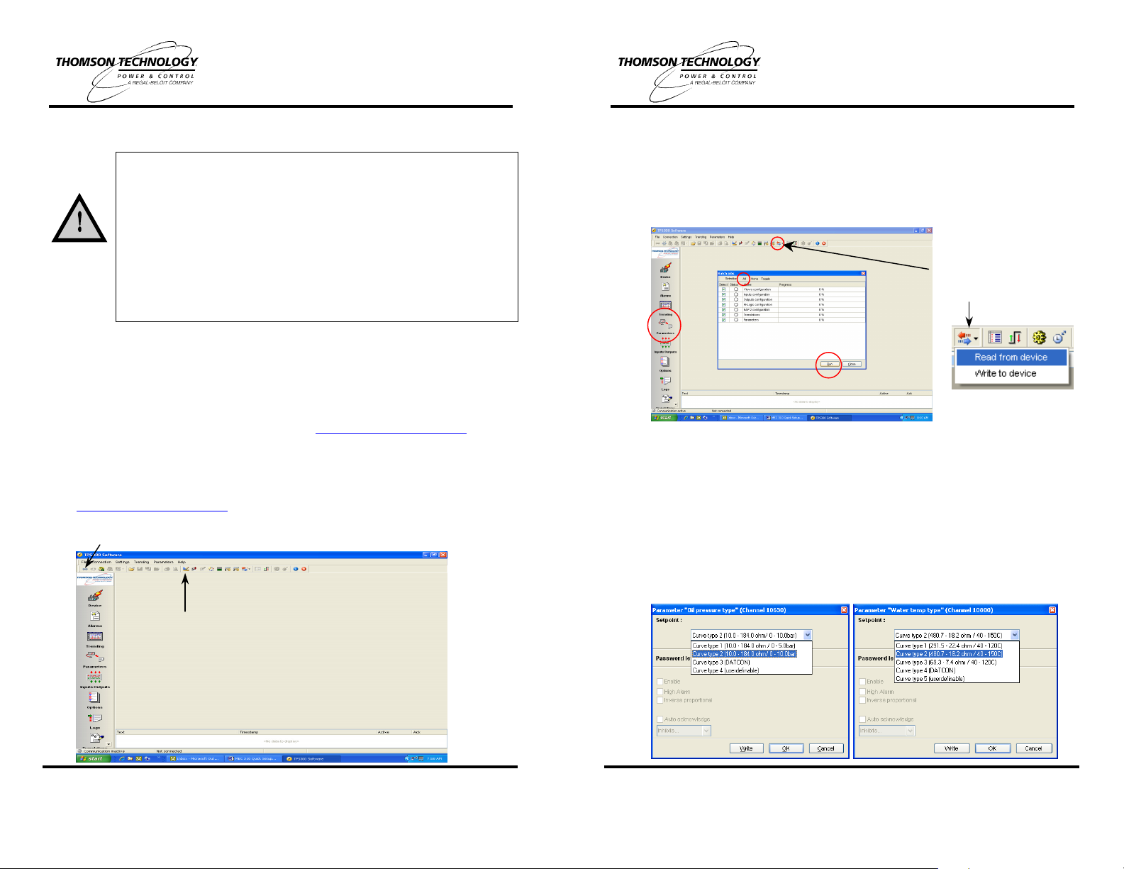
• Click on the ”Batch read and write” Icon and select,” Read from device”. The
“Batch jobs” window will appear (shown below). Select “All” at the top of this
window, then click “Run” at the bottom, a “Save As” window will be presented,
provide a location and file name to save the file. All controller files will be uploaded
so they can be viewed, modify and saved as a common backup file. Once the
upload is complete click the close button, then click on the Parameter ICON on the
left side of the window.
ICON, from drop down menu
select “Read from device”
• Prior to modifying the settings it is recommended to select the type of units of
measurement and the type of configuration each of the 3 multifunction inputs will
used as. These few settings will affect the setpoints and programming fields once
changed. These can be found at Channels 10970 – 11000. Once these have been
changed to the desired type, write these changes to the controller then upload the
Parameter settings again to update the fields in the program menu.
• Select the appropriate curve for the installed VDO oil pressure sensor Parameter
“Oil pressure type” (Channel 10630), then press the “Write” button to send it to
the unit (Curve type 2 Default).
• Select the appropriate curve for the installed VDO water temperature sender
Parameter “Water temp type” (Channel 10800), then press the “Write” button to
send it to the unit (Curve type 2 Default).
THOMSON TECHNOLOGY • 9087A - 198th STREET, LANGLEY, BC, CANADA V1M 3B1
TELEPHONE: (604) 888-0110 • FAX: (604) 888-3381 • E-MAIL: info@thomsontechnology.com •
PM078 REV 2 08/12/02 1
Note: If communications cannot be
achieved the communication port can be
modified by clicking on the application
settings ICON.
www.thomsontechnology.com
THOMSON TECHNOLOGY • 9087A - 198th STREET, LANGLEY, BC, CANADA V1M 3B1
TELEPHONE: (604) 888-0110 • FAX: (604) 888-3381 • E-MAIL: info@thomsontechnology.com •
PM078 REV 2 08/12/02 2
www.thomsontechnology.com
Page 2
MEC 310 Quick Start Guide
Utility/Mains V/f OK
MEC 310 Quick Start Guide
• Set the Alarm and Shutdown Oil Pressure setpoint as recommended by the engine
manufacturer:
o Channel 4310 “Oil pressure 2.1” - Low Oil Pressure Alarm Level.
o Channel 4320 “Oil pressure 2.2” - Low Oil Pressure Shutdown Level.
• Set the Alarm and Shutdown Water Temperature setpoint as recommended by the
engine manufacturer:
o Channel 4460 “Water temp. 3.1” - High Water Temperature Alarm Level.
o Channel 4470 “Water temp. 3.2” - High Water Temperature Shutdown Level.
• Set the Overspeed Shutdown setpoint as recommended by the engine manufacturer:
o Channel 4510 “Overspeed1” - Overspeed1 Shutdown Level.
• Set the Tacho-teeth to match the number of teeth used for the speed sensing device
(typically the number of flywheel teeth):
o Channel 6171 “Tacho-teeth”
• Review, determine protection levels and enable the following protection setpoints;
“Protection” channels 1000 – 1630, “Analogue” channels 4220 - 4970 and “Binary”
channels - 3000 – 3490.
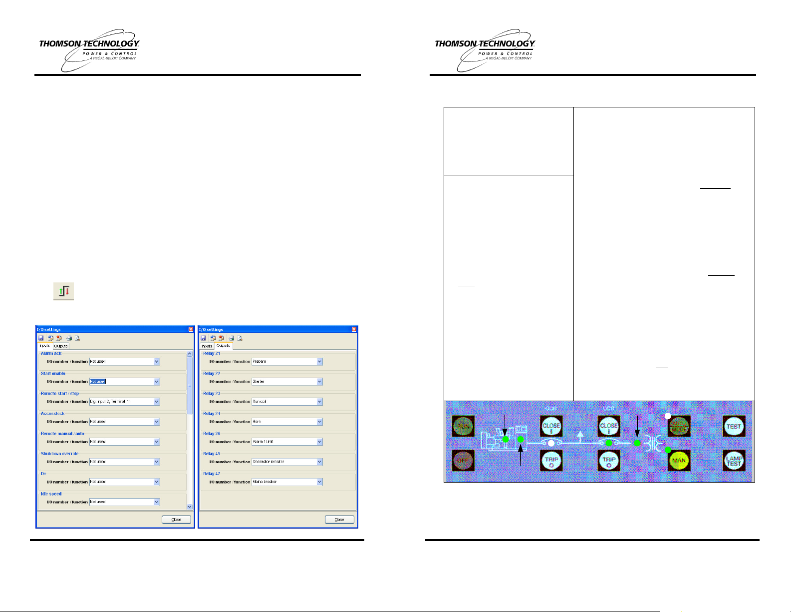
• The “Inputs and Outputs” must be configured to associate each with specific alarms
and control functions. These are setup using the I/O ICON at the top of the window.
• The I/O Setup ICON provides the following screen, which allows setup of the
Inputs under one tab and Outputs under the other (both shown separately). It is
imperative that these be configured to ensure correct input and output operation.
3. Quick Start Operating Instructions for AMF Option
AUTOMATIC OPERATION
Push Green “AUTO/MODE”
button - the Green LED will light
to Indicate the Automatic
Operation Mode is selected.
ON LOAD TEST Feature
(programmable via TPS 300)
• Press the “TEST” button.
• The Generator will start and
the load will transfer to the
generator after preset delays.
• The load will Auto re-transfer
back to Utility/Mains after preprogrammed timed amount Both Channels 7062 “Mains
OK U” and 7072 “Mains OK f”
have 120 sec as default.
• The Generator will continue to
run for programmed Cooldown
Time and stop.
For further detailed information,
refer to the MEC 310 Installation
and Operation Manual.
Speed Detected
MANUAL OPERATION
• Press Yellow “MAN” button - the Green LED
will light to indicate the Manual Operation
Mode is selected.
• Manual Load Transfer to Gen
ο To start Generator press the “RUN” button.
ο Ensure Generator is running normally.
The Green LED on the Engine graphic
symbol will light and the Green LED on the
Alternator graphic symbol will light after a
3 sec delay - Channel 6221 “Hz/V OK”.
ο To transfer the load, first press the UCB
“TRIP(O)” button, then press the GCB
“CLOSE(I)” button.
• Manual Load Re-Transfer to Utility
ο Ensure Utility/Mains Voltage is normal.
All phases “V/f OK” will be indicated by
illumination of the Green LED on the
Transformer graphic symbol.
ο To transfer load, first press the GCB
“TRIP(O)” button, then press the UCB
“CLOSE(I)” button.
Note: LED lights shown on the MEC 310 mimic
bus for the GCB & UCB indicate the position of
output control relays (not the actual position of
the GCB & UCB power switching devices).
PM078 REV 2 08/12/02 3
THOMSON TECHNOLOGY • 9087A - 198th STREET, LANGLEY, BC, CANADA V1M 3B1
TELEPHONE: (604) 888-0110 • FAX: (604) 888-3381 • E-MAIL: info@thomsontechnology.com •
www.thomsontechnology.com
Gen V/f OK
Note: The manual control push buttons, for GCB and UCB (close/trip) controls are not
PM078 REV 2 08/12/02 4
available in non-AMF model controllers.
THOMSON TECHNOLOGY • 9087A - 198th STREET, LANGLEY, BC, CANADA V1M 3B1
TELEPHONE: (604) 888-0110 • FAX: (604) 888-3381 • E-MAIL: info@thomsontechnology.com •
www.thomsontechnology.com
 Loading...