

MEC 310
APPLICATION NOTES
M-Logic
Internal Logic Controller
r. 0556B
PM103 Rev 0 09/08/20
9087A – 198th Street, Langley, BC Canada V1M 3B1 Ÿ Telephone (604) 888-0110
Telefax (604) 888-3381 Ÿ E-Mail: info@thomsontechnology.com Ÿ www.thomsontechnology.com

This document covers the following products:
MEC 310 SW version 1.2X.X
Utility Software TPS300 version 3.10.1 and later.

Table of Contents
MEC 310 APPLICATION NOTES, M-Logic
1. ABOUT THIS DOCUMENT..........................................................................................................1
ENERAL PURPOSE
G
NTENDED USERS
I
2. WARNINGS AND LEGAL INFORMATION...............................................................................2
EGAL INFORMATION AND RESPONSIBILITY
L
LECTROSTATIC DISCHARGE AWARENESS
E
AFETY ISSUES
S
ACTORY SETTINGS
F
EFINITIONS
D
3. GENERAL DESCRIPTION ...........................................................................................................4
NTRODUCTION
I
4. CONFIGURATION ........................................................................................................................5
TARTING
S
EAD/WRITE
R
AVE/OPEN
S
ASIC FUNCTIONS
B
EFINITIONS
D
XAMPLES
E
5. LIST OF EVENTS AND COMMANDS.......................................................................................13
MEC 310 ............................................................................................................................................ 13
..............................................................................................................................................5
.............................................................................................................................................9
.................................................................................................................................1
....................................................................................................................................1
.............................................................................................2
................................................................................................2
.......................................................................................................................................2
................................................................................................................................2
..........................................................................................................................................2
......................................................................................................................................4
..........................................................................................................................................6
............................................................................................................................................6
...................................................................................................................................7
..........................................................................................................................................9
PM103 R0 09/08/20 THOMSON TECHNOLOGY
MEC 310 APPLICATION NOTES, M-Logic
Please make sure to read this handbook before working with the MEC 310
set to be controlled. Failure to do this could result in
1. About this document
General purpose
This document is the M-Logic handbook for Thomson Technology’s MEC 310 Generator
Controller. The document mainly includes a general description, information about programming,
overall configuration and relay configuration.
The general purpose of this handbook is to inform the intended users about programming and
configuration of the M-Logic tool.
Intended users
The handbook is mainly intended for the person responsible for the unit setup. In most cases, this
would be a panel builder designer. Naturally, other users might also find useful information in the
handbook.
controller and the gendamage to the equipment or human injury.
PM103 R0 09/08/20 Page 1 THOMSON TECHNOLOGY
MEC 310 APPLICATION NOTES, M-Logic
ll be helpful for the reader to
Be aware of the hazardous live currents and voltages. Do not touch any AC
2. Warnings and legal information
This chapter includes important information about general legal issues relevant in the handling of
Thomson Technology products. Furthermore, some overall safety precautions will be introduced
and recommended. Finally, the highlighted notes and warnings, which will be used throughout the
document, are presented.
Legal information and responsibility
Thomson Technology takes no responsibility for installation or operation of the generator set. If
there is any doubt about how to install or operate the generator set controlled by the unit, the
company responsible for the installation or the operation of the set must be contacted.
The units are not to be opened by unauthorized personnel. If opened anyway, the
warranty will be lost.
Electrostatic discharge awareness
Sufficient care must be taken to protect the terminals against static discharges during the
installation. Once the unit is installed and connected, these precautions are no longer necessary.
Safety issues
Installing the unit implies work with dangerous currents and voltages. Therefore, the installation
should only be carried out by authorized personnel who understand the risks involved in working
with live electrical equipment.
measurement inputs as this could lead to injury or death.
Factory settings
The unit is delivered with certain factory settings. Given the fact that these settings are based on
average values, they are not necessarily the correct settings for matching the individual engine.
Thus precautions must be taken to check the settings before running the engine.
Definitions
Throughout this document a number of notes and warnings will be presented. To ensure that these
are noticed, they will be highlighted in order to separate them from the general text.
Notes
PM103 R0 09/08/20 Page 2 THOMSON TECHNOLOGY
The notes provide general information which wi
bear in mind.

The warnings indicate a potentially dangerous situation, which could result
in death, personal injury or damaged equipment, if certain guidelines are not
Warnings
followed.
MEC 310 APPLICATION NOTES, M-Logic
PM103 R0 09/08/20 Page 3 THOMSON TECHNOLOGY

MEC 310 APPLICATION NOTES, M-Logic
3. General description
This chapter includes overall product information about the unit in general and its place in the
Thomson Technology product range.
Introduction
The M-Logic is a small logic controller incorporated in the MEC 310 controller. Even though it is a
logic controller, it must not be confused with a PLC. The M-Logic can be compared with a PLC
limited in functionality and can only be used for uncomplicated tasks.
The M-Logic can carry out binary control functions only; there are no possibilities for analogue
reading and/or control functions.
The M-Logic can be programmed from the free PC tool called TPS 300 Utility Software (ver. 3).
The TPS 300 software can be downloaded from:
www.thomsontechnology.com
M-Logic setting is done in command lines. There are 40 lines, and each line contains 3 events, 2
operators and one output with a possibility to make a time delay.
If 3 operators are not enough, a number of virtual events can be used to pass the control on to
another line and carry on there. This makes it possible to build larger event based controls.
PM103 R0 09/08/20 Page 4 THOMSON TECHNOLOGY

MEC 310 APPLICATION NOTES, M-Logic
4. Configuration
Starting
Once TPS 300 has been started, there will be an icon on the lower lefthand side to activate M-Logic.
Click the icon, and the following screen appears:
PM103 R0 09/08/20 Page 5 THOMSON TECHNOLOGY

MEC 310 APPLICATION NOTES, M-Logic
Read/write
When the M-Logic screen is shown, the M-Logic toolbar appears at the top of the screen. The
toolbar has two buttons which are used to write and read the M-Logic configuration to and from the
unit.
The M-Logic configuration can also be saved/opened to/from a file using the default save/open
buttons.
Read M-Logic settings from the unit
Activating this button will read all M-Logic settings from the unit to TPS 300.
Write M-Logic settings to the unit
Activating this button will write the M-Logic settings from TPS 300 to the unit.
Save/open
Save
Activating this button makes it possible to save the M-Logic configuration to file
(part of the general MEC 310 configuration file “.USW”).
Open
Activating this button makes it possible to open a previously saved logics file.
PM103 R0 09/08/20 Page 6 THOMSON TECHNOLOGY
MEC 310 APPLICATION NOTES, M-Logic
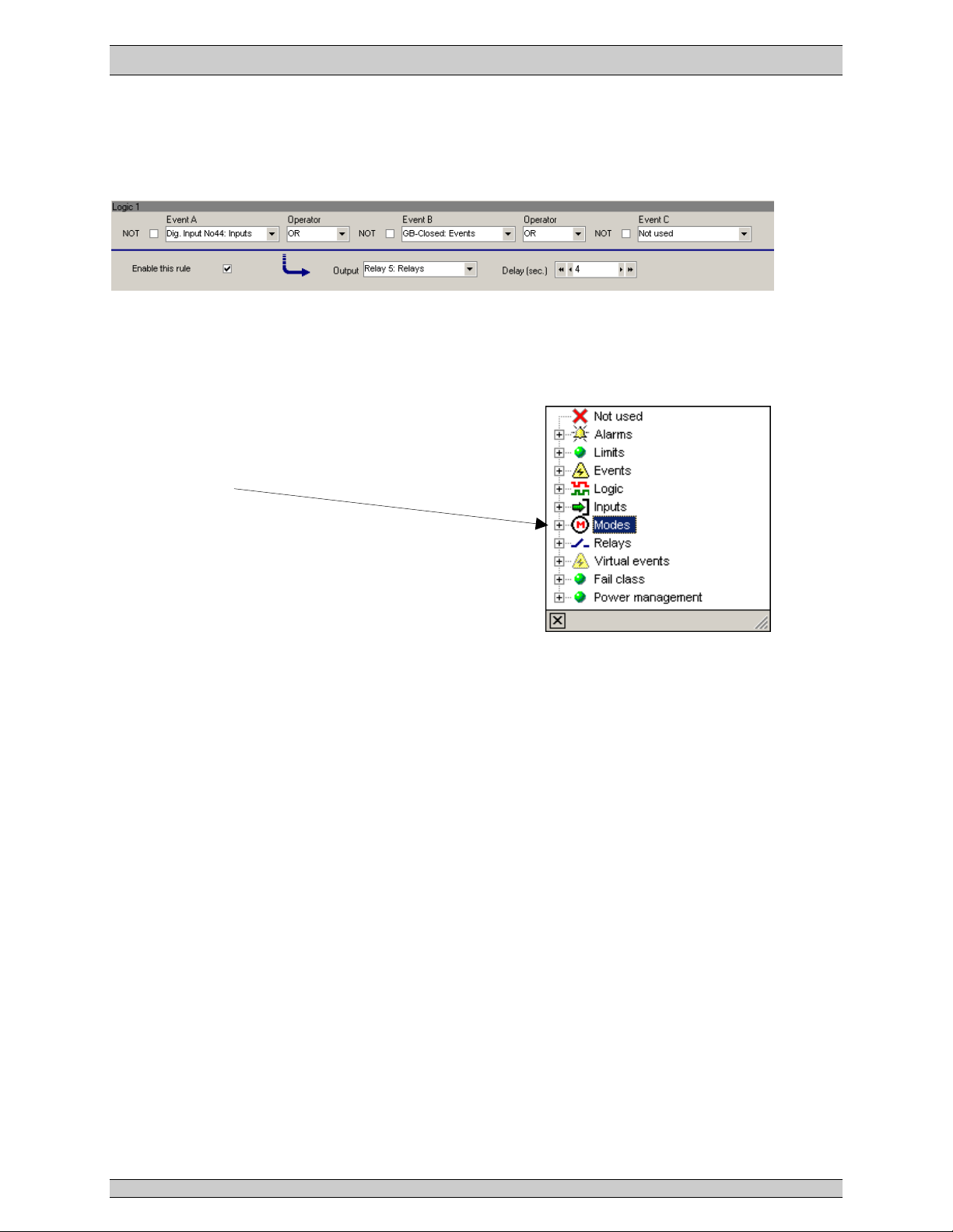
Basic functions
The M-Logic consists of a number of “lines”, Logic 1, Logic 2 and so on. Each of these lines have
3
The available functions are:
Events A, B and C
These are used to trigger the logic.
Note that for each event the function “NOT” can be selected
to get an inverted function.
When opening the roll-down window of the events, this
window appears:
Alarms: Use an alarm to activate.
Limits: Same as alarms, only with no time delay.
Events: Events that are not alarms, e.g.
Logic: Can be TRUE or FALSE. TRUE means always, FALSE means never.
Inputs: Direct activation of a binary input. The availability of binary inputs is
Modes: Are running modes and plant modes, e.g. “AUTO”.
Relays: Activation when a relay activates. The availability of relay outputs is
Virtual
events: Is a number of internal (virtual) events that can be activated from another logic
Fail class: The event activates upon activation of any alarm with the chosen fail class,
Command
timers
1 s pulse: If the activating (triggering) event is required to be a pulse, these can be used.
Power Manage-
ment: Status related to power management, e.g. “Engine 1 running”.
event
settings, 2
operator
settings, an
enable
tick box and one
output
setting.
“Engine running”.
option dependent.
option dependent.
line. By using these virtual events, the number of activating (triggering) events
can be expanded from the 3 available in each logic line to, in theory, an
unlimited number of events.
e.g. “Shutdown”.
PM103 R0 09/08/20 Page 7 THOMSON TECHNOLOGY

MEC 310 APPLICATION NOTES, M-Logic
If a relay output is chosen, the relay in question must be set up to be an
Operators
2 operators are available, and they can be:
“OR” (any operator activates the function output),
“AND” (all activated operators must have status ON to activate the function output).
Enable the rule
If this tick box is not ticked, the logic in question will not operate.
Output
This is the selection of the reaction of the system upon activation of the function. Note that the
output has a delay function. If set to 0 s (default), there is no delay.
Relays: Selection of a relay output. The selection of
these is option-dependent.
Commands: Command to the Multi-line unit, e.g. select
AUTO running mode.
Virtual events: Is a number of internal (virtual) events that
can be activated and used in another logic
line. By using these virtual events, the number
of activating (triggering) events can be
expanded from the 3 available in each logic
line to, in theory, an unlimited number of
events.
Virtual events can also be trigged from Modbus.
Alarm LED: The availability of the alarm LEDs is dependent on the module in question. The
above example comes from a MEC 310 where 4 LEDs are mounted on the display
front.
Inhibits: A selection of inhibit functions for the alarms.
Buzzer: Incorporated buzzer (MEC 310) or buzzer in the additional operator panel (MEC
310/EAP 300). Control of activation and deactivation of the buzzer (e.g. with
alarms).
alarm/limit output (input/output settings, icon in the top of TPS 300).
PM103 R0 09/08/20 Page 8 THOMSON TECHNOLOGY

MEC 310 APPLICATION NOTES, M-Logic
Definitions
The TRUE and FALSE states are explained below.
A TRUE state of an input/event will be detected, if the condition defined in the input/event is met.
Examples given:
Digital input is TRUE when activated (12/24V DC applied)
Alarm condition is TRUE when the alarm is present
Mode condition is TRUE when the mode is selected
A FALSE state of an input event will be detected, if the condition defined in the input event is
met.
Examples given:
Digital input is FALSE when deactivated (12/24V DC not applied)
Alarm condition is FALSE when the alarm is not present
Mode condition is FALSE when the mode is not selected
not
Examples
By using the events, rules can be made for the use of the M-Logic.
Virtual events
Virtual events are used to expand the number of events in a logic sequence.
The following shows how the output of Logic 1 is used to continue the sequence in Logic 2.
The Logic 1 output is set to Virtual Event 1.
The Event A in Logic 2 is Virtual Event 1.
This gives a total of 5 events that can be used in this logic sequence (A + B + C in Logic 1 and B
+ C in Logic 2).
Set/reset function
If you use a single binary input for e.g. selection of AUTO/MANUAL, you need a SET/RESET
function, since 2 binary inputs are normally required for this.
In the following example, binary input no. 10 is used to switch between AUTO (input ON) and
PM103 R0 09/08/20 Page 9 THOMSON TECHNOLOGY

MEC 310 APPLICATION NOTES, M-Logic
MANUAL (input OFF).
First line: If input 10 = ON and AUTO = OFF (NOT Auto operation mode), then set
AUTO mode command.
Second line: If input 10 = OFF and MANUAL = OFF (NOT Manual operation), then set
MANUAL mode command.
In M-Logic, it looks like this:
Toggle function
Using a single button to toggle between 2 running modes.
In this example, the button no. 1 on the EAP-2 (configured in a separate tool) is used to activate
Virtual event 1. Logic 1 selects AMF if the mode is NOT AMF, and Logic 2 selects LTO mode if
the mode is NOT LTO. In this way, one single button can be used for toggling between AMF and
LTO modes.
EAP 300 configurator
The window below appears.
Read the present setting by clicking here:
PM103 R0 09/08/20 Page 10 THOMSON TECHNOLOGY

MEC 310 APPLICATION NOTES, M-Logic
Click button 1 and you select this:
The item text can be written freely and printed, so it can be put in the EAP-2 front pockets.
Click OK and close the EAP-2 window.
Select M-Logic (bottom left-hand side).
PM103 R0 09/08/20 Page 11 THOMSON TECHNOLOGY

MEC 310 APPLICATION NOTES, M-Logic
Controlling a relay output with one single EAP button
In this example, the relay can be replaced by any other output, and the EAP button can be
replaced by e.g. a binary input.
The button of the EAP-2 must be set to activate Virtual Event 1 (VE 1) (in this case).
In Logic 1, the VE 1 will activate the relay output (26). At the same time, the relay output (26) will
remain ON, unless Virtual Event 2 (VE 2) is activated (AND NOT VE 2).
In Logic 2, the VE 1 will activate VE 2 if the relay output (26) is ON (AND Relay output (26)).
The result is that the relay changes position every time the EAO button is activated.
Power up in a specific mode
In the above example, the unit will always power up in manual mode. The timer in Logic 1 sets the
output for 5 s, and this is used to set manual mode in event 2. When the timer expires, you can
freely select any mode since the virtual event 1 turns ON and the Logic 2 says NOT virtual event
1.
PM103 R0 09/08/20 Page 12 THOMSON TECHNOLOGY

MEC 310 APPLICATION NOTES, M-Logic
lists are those used in the Designer’s Reference
Handbook and the description of options. Please refer to these documents for
5. List of events and commands
The terms used in the
detailed explanations.
If there are no references to the function in question, the reference can be
found in the Designer’s Reference Handbook.
MEC 310
Events
Event Description Notes
Alarms All alarms available in the alarm list are
Events
Logic TRUE (= always)
available as events. Note that the list
will show all alarms, also those that are
not available in the present
configuration of basic unit and options.
Mains failure Mains failure relates to option A.
Diesel generator V/Hz OK
Engine running
Ready to auto start
Cranking
Service timer 1
Service timer 2
Engine heater active
Fuel pump active
Lamp test
Nominal settings 1
Nominal settings 2
Nominal settings 3 (single phase) 1 phase + Neutral.
Nominal settings 4 (split phase) 2 phases + Neutral with 180o phase
angle between phases.
Parameter group 1
Parameter group 2
Parameter group 3
Simple test function Simple test relates to option A.
Idle mode
Alarm buzzer on EAP-2-1
Alarm buzzer on EAP-2-2
Access lock
Mute horn button
LTO with AMF active LTO (Load Take Over) relates to option
EAP-300 (Additional Operator Panel)
relates to feature EAP 300.
A.
PM103 R0 09/08/20 Page 13 THOMSON TECHNOLOGY

MEC 310 APPLICATION NOTES, M-Logic
Event Description Notes
Inputs
FALSE(= never)
MB closed MB (Mains Breaker) relates to option A.
MB open
GB closed GB = Generator Breaker.
GB open
Digital input terminal 10-15
Multifunctional input terminal 1-3
Ext. I/O dig. in. 1-16 External I/Os relate to feature EXP.
Modes
Manual operation
Test sequence Test sequence relates to option A.
Auto operation
Island mode
AMF (Automatic Mains Failure) mode AMF mode relates to option A.
LTO mode LTO mode relates to option A.
Relays
Relays no. 21-24
Relay no. 26
Relay no. 45
Relay no. 47
External I/O dig. out. 1-16 External I/O relates to feature EXP.
Virtual
events
Virtual event 1-10
These are used as interconnection
between multiple logics to enhance the
possible number of events in one
sequence.
Fail class
Warning
Trip GB
Trip and stop
Shutdown
Command
timers
Command timer 1-8
The command timers will issue a 1 s
pulse, enough to trigger an event.
Operators
Operator Description Notes
OR Using OR between 2 events means that
the output will activate when one of
these activates.
AND Using AND between 2 operators means
that the output will only activate if both
events are activated.
Outputs
Output Description Notes
Relays Selectable number of relays are option
dependent
The list will show all relays possible
including optional ones. Make sure that
a selected relay is actually present.
PM103 R0 09/08/20 Page 14 THOMSON TECHNOLOGY

MEC 310 APPLICATION NOTES, M-Logic
Output Description Notes
Command
s
AUTO operation
MANUAL operation
Island mode
AMF mode AMF mode relates to option A.
LTO mode
Lamp test
Ack. all alarms
Switch to nominal settings 1
Switch to nominal settings 2
Switch to nominal settings 3
Switch to nominal settings 4
Mute horn relay
Start gen-set Reacts in MANUAL mode only.
Stop gen-set Reacts in MANUAL mode only.
Open GB Reacts in MANUAL mode only.
Close GB Reacts in MANUAL mode only.
Open MB Reacts in MANUAL mode only.
Close MB Reacts in MANUAL mode only.
Virtual
events
Virtual event 1-10
These are used as interconnection
between multiple logics to enhance the
possible number of events in one
sequence.
Alarm LED
Alarm LED 1
Alarm LED 2
Alarm LED 3
Alarm LED 4
The alarm LEDs are placed to the right
of the display on the unit front. Possible
choices are:
- red + blink
- red (steady)
- yellow + blink
- yellow (steady)
- green + blink
- green (steady)
Inhibits
Deactivate mode selection
Deactivates the AUT and MAN mode
buttons on the MEC 310.
Inhibit alarm ack. in auto Prevents the use of the binary input
“alarm ack.” when in AUTO running
mode.
Inhibit ext. comm. Inhibits alarms related to engine
communication (option J).
Buzzer
Inhibit 1
Inhibit 2
Inhibit 3
Activate buzzer on main unit
Inhibit 1, 2 and 3 are used for alarm
inhibit. Remember to activate inhibit in
the alarm in question.
Main unit is the MEC 310 unit.
Deactivate buzzer on main unit
Activate buzzer on EAP-2-1
Deactivate buzzer on EAP-2-1
Activate buzzer on EAP-2-2
Deactivate buzzer on EAP-2-2
Ack. alarm buzzer on EAP-2-1
EAP 300 units are external Additional
Operator Panels. The setup of these is
made in a separate M-Logic-like setting
(EAP-2 configuration icon on top of the
USW screen).
Ack. alarm buzzer on EAP-2-2
PM103 R0 09/08/20 Page 15 THOMSON TECHNOLOGY

MEC 310 APPLICATION NOTES, M-Logic
Thomson Technology reserves the right to change any of the above.
PM103 R0 09/08/20 Page 16 THOMSON TECHNOLOGY
 Loading...