

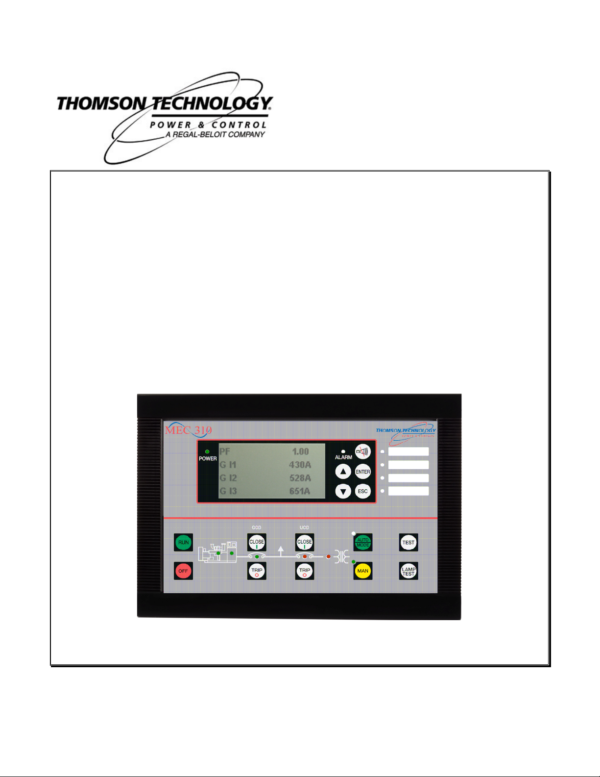
MEC 310
GENSET CONTROLLER
Option M – Modbus Communications
r.0442C
9087A – 198th Street, Langley, BC Canada V1M 3B1 Telephone (604) 888-0110
Fax (604) 888-3381 E-Mail: info@thomsontechnology.com www.thomsontechnology.com
PM080 Rev 0 07/06/18


MEC 310 GENSET CONTROLLER WITH MODBUS
TABLE OF CONTENTS
1. WARNINGS AND LEGAL INFORMATION................................................................... 1
EGAL INFORMATION AND RESPONSIBILITY
L
LECTROSTATIC DISCHARGE AWARENESS
E
AFETY ISSUES
S
EFINITIONS
D
................................................................................................................... 1
....................................................................................................................... 1
............................................................................. 1
............................................................................. 1
2. DESCRIPTION OF OPTION ......................................................................................... 2
ANSI
O
T
H
W
NUMBERS
PTION
ERMINAL DESCRIPTION
ARDWARE SETTINGS
M - M
IRING
.............................................................................................................................. 2
.................................................................................................................. 2
ODBUS
.......................................................................................................... 2
....................................................................................................... 2
......................................................................................................... 2
3. PARAMETER LIST ....................................................................................................... 3
4. DATA TABLES.............................................................................................................. 4
ONFIGURABLE AREA (READ ONLY
C
EASUREMENT TABLE (READ ONLY
M
LARM AND STATUS TABLE (READ ONLY
A
ONTROL REGISTER TABLE READ
C
OMMAND FLAGS TABLE (WRITE ONLY
C
TATUS FLAGS TABLE (READ ONLY
S
FUNCTION CODE 04H
) (
FUNCTION CODE 04H
) (
FUNCTION CODE 04H
) (
(03H)/
WRITE
) (
FUNCTION CODE 02H
) (
(10H) ............................................................ 17
FUNCTION CODE 0FH
) ..................................................... 4
) .................................................... 9
)............................................ 12
).............................................. 18
)................................................... 19
PM080 Rev 0 07/06/18 Thomson Technology
The notes provide general information which will be helpful for the reader to
The warnings indicate a potentially dangerous situation which could result in
t
followed.
Be aware of the hazardous live currents and voltages. Do not touch any AC
1. Warnings and legal information
Legal information and responsibility
Thomson Technology takes no responsibility for installation or operation of the generator set. If there is any
doubt about how to install or operate the generator set controlled by the unit, the company responsible for the
installation or the operation of the set must be contacted.
The units are not to be opened by unauthorised personnel. If opened anyway, the
Sufficient care must be taken to protect the terminals against static discharges during the installation. Once the
unit is installed and connected, these precautions are no longer necessary.
Installing the unit implies work with dangerous currents and voltages. Therefore, the installation should only be
carried out by authorised personnel who understand the risks involved in working with live electrical equipment.
measurement inputs as this could lead to injury or death.
warranty will be lost.
Electrostatic discharge awareness
Safety issues
Definitions
Throughout this document a number of notes and warnings will be presented. To ensure that these are noticed,
they will be highlighted in order to separate them from the general text.
Notes
Warning
bear in mind.
death, personal injury or damaged equipment, if certain guidelines are no
PM080 Rev 0 07/06/18 1 Thomson Technology
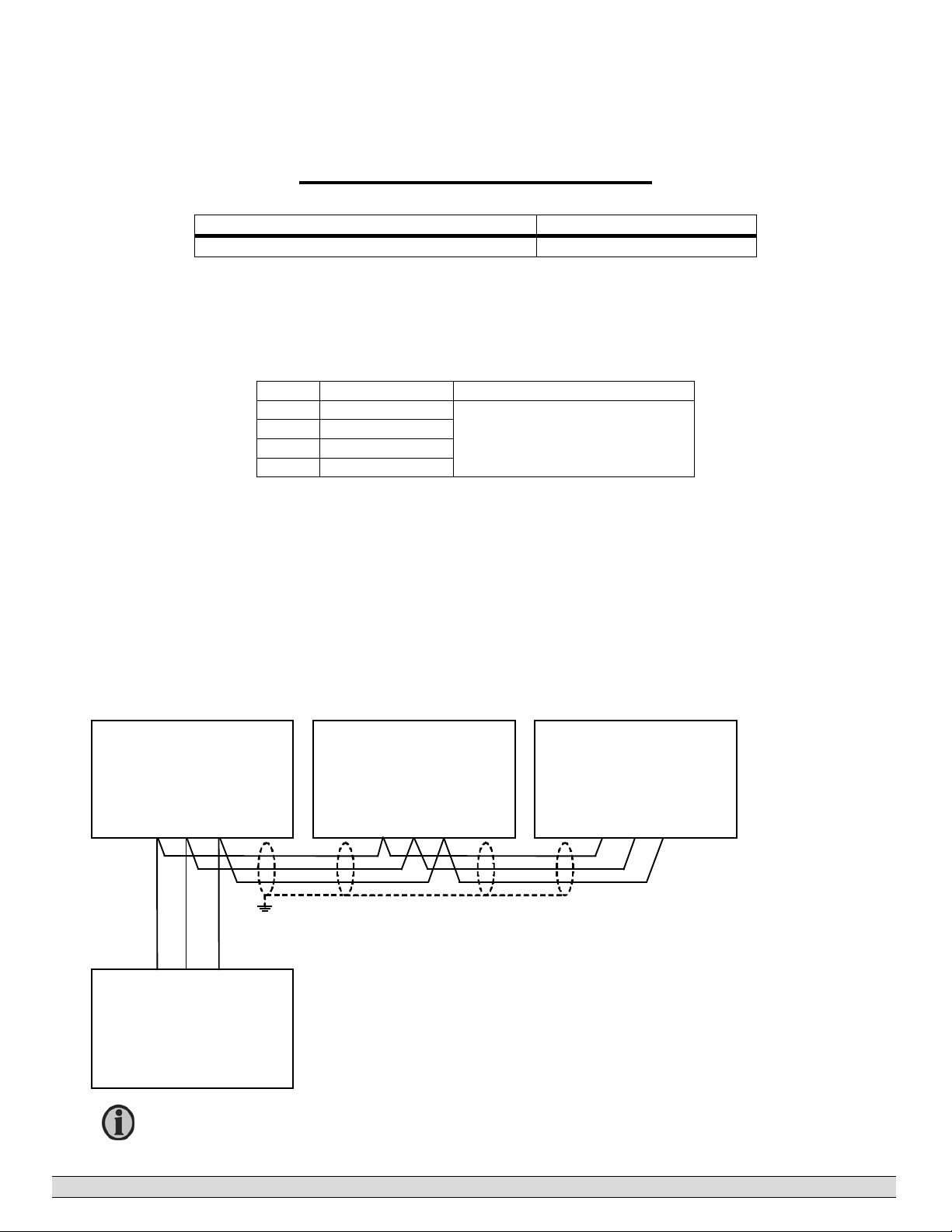
MEC310
MEC310
MEC310
PLC
2
) twisted pair,
shielded, <40 m
/m, min. 95% shield coverage.
2. Description of option
ANSI numbers
Function ANSI no.
RS485 modbus communication -
Option M - Modbus
The Modbus option is a hardware and software option.
Terminal description
Term. Function Description
49 DATA - (Tx)
50 GND
51 DATA + (Rx)
52 Not used
Modbus RTU, RS485
Hardware settings
These are the MEC 310 RS485 hardware settings:
a. 9600 or 19200 bps
b. 8 data bits
c. None parity
d. 1 stop bit
Modbus Slave
GND
Rx
49
50
51
Data
GND
Data
Rx
Tx
Tx
Modbus Slave
GND
Rx
50
51
Wiring
Tx
49
Modbus Slave
Tx
GND
Rx
49
50
51
Modbus Master
PM080 Rev 0 07/06/18 2 Thomson Technology
Cable: Belden 3105A or equivalent. 22 AWG (0.6 mm
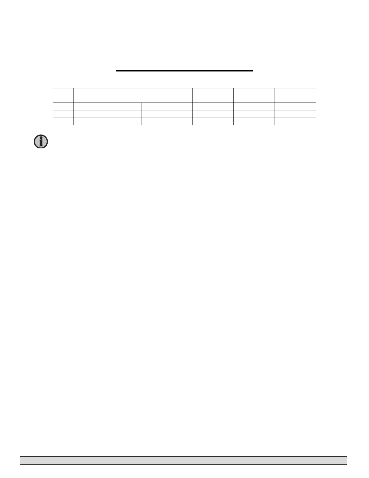
The mode ASCII is used for modem communication (ASCII: 7 data bit. RTU: 8
7510 Ext. communication
No. Setting Min. setting Max. setting Factory
7511 Ext. communication ID 1 247 1
7512 Ext. communication Baud rate 9600 Baud 19200 Baud 9600 Baud
7513 Ext. communication Mode RTU ASCII RTU
data bit).
3. Parameter list
setting
PM080 Rev 0 07/06/18 3 Thomson Technology

4. Data tables
Example:
Read measured Supply Voltage (U
1. Determine required parameters:
MEC 310 ID (default) = 01h
Function Code (Read) = 04h
Offset Address (from table below) = 34d -> 22h
Request length of 1 word = 01h
2. Create and send Modbus command; receive response:
Tx: 01h 04h 00h 22h 00h 01h 91h C0h
Rx: 01h 04h 02h 00h EDh 79h 7Dh
Where the last two words of each message are automatically generated CRC codes
3. Interpret Data:
Read 00 ED h = 237d [V/10] = 23.7 V
Configurable area (read only) (function code 04h)
Address Content Type
0 U
1 U
2 U
3 U
4 U
5 U
6 f
7 IL1 Generator current. Measured in [A]
8 IL2 Generator current. Measured in [A]
9 IL3 Generator current. Measured in [A]
10 P
11 Q
12 S
13 Cos-phi -99...0...100 generator cosinus-phi. Measured in cos-
16 [HI]
17 [LO]
18 U
19 U
20 U
21 U
22 U
23 U
24 F
Generator voltage. Measured in [V]
L1-L2
Generator voltage. Measured in [V]
L2-L3
Generator voltage. Measured in [V]
L3-L1
Generator voltage. Measured in [V]
L1-N
Generator voltage. Measured in [V]
L2-N
Generator voltage. Measured in [V]
L3-N
L1
Generator active power. Measured in [kW]. Negative
GEN
Generator reactive power. Measured in [kVAr]. Positive
GEN
Generator apparent power. Measured in [kVA]
GEN
E
Energy counter. Measured in [kWh]. Max. 300000
GEN
MainsL1-L2
MainsL2-L3
MainsL3-L1
MainsL1-N
MainsL2-N
MainsL3-N
Mains frequency L1. Measured in [Hz/100]
Mains
).
SUPPLY
Generator freq. Measured in [Hz/100]
value means reverse power
value means generated inductive reactive power
phi:100. Negative value means capacitive cos-phi
MWh
Mains voltage. Measured in [V]
Mains voltage. Measured in [V]
Mains voltage. Measured in [V]
Mains voltage. Measured in [V]
Mains voltage. Measured in [V]
Mains voltage. Measured in [V]
PM080 Rev 0 07/06/18 4 Thomson Technology

Address Content Type
27 Alarms Number of alarms
28 Alarms Number of unack. alarms
29 Start attempts Start attempts
30 [HI]
Abs. run. hours Hour
31 [LO]
32 GB
33 MB
34 U
GB operations counter
oper
MB operations counter
oper
Supply voltage. Measured in [V/10]
SUPPLY
36 RPM RPM
37 Multi input term 6, unscaled
38 Multi input term 7, unscaled
39 Multi input term 8, unscaled
48
Protection
alarms
49 Protection
alarms
51 Synchronisation Bit 0
Bit 0
Bit 1
Bit 2
Bit 3
Bit 4
Bit 5
Bit 6
Bit 7
Bit 8
Bit 9
Bit 10
Bit 11
Bit 12
Bit 13
Bit 14
Bit 15
Bit 0
Bit 1
Bit 2
Bit 3
Bit 4
Bit 5
Bit 6
Bit 7
Bit 8
Bit 9
Bit 10
Bit 11
Bit 12
Bit 13
Bit 14
Bit 15
1000 G -P> 1
1030 G I> 1
1040 G I> 2
1150 G U> 1
1170 G U< 1
1210 G f> 1
1240 G f< 1
PM080 Rev 0 07/06/18 5 Thomson Technology

Address Content Type
alarms
Bit 1
Bit 2
Bit 3
Bit 4
Bit 5
Bit 6
Bit 7
Bit 8
Bit 9
Bit 10
Bit 11
Bit 12
Bit 13
Bit 14
Bit 15
53 Digital inputs
Bit 0
Bit 1
Bit 2
Bit 3
Bit 4
Bit 5
Bit 6
Bit 7
Bit 8
Bit 9
Bit 10
Bit 11
Bit 12
Bit 13
Bit 14
Bit 15
54 Digital inputs
Bit 0
Bit 1
Bit 2
Bit 3
Bit 4
Bit 5
Bit 6
Bit 7
Bit 8
Bit 9
Bit 10
Bit 11
Bit 12 3490 Dig. input 19-20, emergency
2150 Phase seq. error
2160 GB open failure
2170 GB close failure
GB pos. failure
2200 MB open failure
2210 MB close failure
MB pos. failure
3000
3010
3020
3030
3040
3050
Dig. input 1
Dig. input 2
Dig. input 3
Dig. input 4
Dig. input 5
Dig. input 6
3400 Dig. multi input 6
3410 Dig. multi input 7
3420 Dig. multi input 8
stop
PM080 Rev 0 07/06/18 6 Thomson Technology

Address Content Type
Bit 13
Bit 14
Bit 15
57
Bit 0
Bit 1
Bit 2
Bit 3
Bit 4
Bit 5
Bit 6
Bit 7
Bit 8
Bit 9
Bit 10
Bit 11
Bit 12
Bit 13
Bit 14
Bit 15
58
Bit 0
Bit 1
Bit 2
Bit 3
Bit 4
Bit 5
Bit 6
Bit 7
Bit 8
Bit 9
Bit 10
Bit 11
Bit 12
Bit 13
Bit 14
Bit 15
59
Bit 0
Bit 1
Bit 2
Bit 3
Bit 4
Bit 5
Bit 6
Bit 7
Bit 8
Bit 9
Multi input 1.1
Multi input 1.2
W. failure, multi input 1
Multi input 2.1
Multi input 2.2
W. failure, multi input 2
Multi input 3.1
Multi input 3.2
W. failure, multi input 3
4510 Overspeed 1
4520 Overspeed 2
4620 VDO fuel level 1.3
4610 Charger generator
4600 V-Belt
4550 Generator Hz/V failure
4570 Start failure
5000 Relay 21
5010 Relay 22
5020 Relay 23
5030 Relay 24
5040 Relay 26
Manual
Auto
Test
Island
AMF
PM080 Rev 0 07/06/18 7 Thomson Technology

Address Content Type
60 Communication
Bit 10
Bit 11
Bit 12
Bit 13
Bit 14
Bit 15
Bit 0
Bit 1
Bit 2
Bit 3
Bit 4
Bit 5
Bit 6
Bit 7
Bit 8
Bit 9
Bit 10
Bit 11
Bit 12
Bit 13
Bit 14
Bit 15
AMF active
7570 EIC comm. error
7580 EIC warning
7590 EIC shutdown
7600 EIC overspeed
7610 EIC coolant temp. 1
7620 EIC coolant temp. 2
7630 EIC oil pressure 1
7640 EIC oil pressure 2
PM080 Rev 0 07/06/18 8 Thomson Technology

Measurement table (read only) (function code 04h)
Address Content Type
Application version
500
U
Generator voltage. Measured in [V]
501
502
503
504
505
506
507
513
514
515
516
517
518
519
520
521
522
523
524
525
526
527
536 [HI]
537 [LO]
538
539
540
541
542
543
544
545
L1-L2
U
Generator voltage. Measured in [V]
L2-L3
U
Generator voltage. Measured in [V]
L3-L1
U
Generator voltage. Measured in [V]
L1-N
U
Generator voltage. Measured in [V]
L2-N
U
Generator voltage. Measured in [V]
L3-N
f
Generator freq.
gen
Measured in [Hz/100]
IL1 Generator current. Measured in [A]
IL2 Generator current. Measured in [A]
IL3 Generator current. Measured in [A]
PL1 Generator active power. Measured in [kW]. Negative value
means reverse power
PL2 Generator active power. Measured in [kW]. Negative value
means reverse power
PL3 Generator active power. Measured in [kW]. Negative value
means reverse power
P
Generator total active power. Measured in [kW]. Negative
GEN
value means reverse power.
QL1 Generator reactive power. Measured in [kVAr]. Positive
value means generated inductive reactive power
QL2 Generator reactive power. Measured in [kVAr]. Positive
value means generated inductive reactive power
QL3 Generator reactive power. Measured in [kVAr]. Positive
value means generated inductive reactive power
Q
Generator total reactive power. Measured in [kVAr].
GEN
Positive value means generated inductive reactive power
SL1 Generator apparent power. Measured in [kVA]. Positive
value means generated inductive reactive power
SL2 Generator apparent power. Measured in [kVA]. Positive
value means generated inductive reactive power
SL3 Generator apparent power. Measured in [kVA]. Positive
value means generated inductive reactive power
S
Generator total apparent power. Measured in [kVA].
GEN
Positive value means generated inductive reactive power
E
Total energy counter. Measured in [kWh]. Max.
GEN
300000MWh
Cos -99...0...100 Generator cos . Measured in cos x 100.
Negative value means capacitive cos
U
Mains voltage. Measured in [V]
L1-L2
U
Mains voltage. Measured in [V]
L2-L3
U
Mains voltage. Measured in [V]
L3-L1
U
Mains voltage. Measured in [V]
L1-N
U
Mains voltage. Measured in [V]
L2-N
U
Mains voltage. Measured in [V]
L3-N
f
Mains freq. Measured in [Hz/100]
Mains
PM080 Rev 0 07/06/18 9 Thomson Technology

Address Content Type
554 [HI]
Running time Absolute running hour counter
555[LO]
Number of alarms
558
Number of unacknowledged alarms
559
Number of acknowledged active alarms
560
GB
Generator/circuit breaker operations counter
563
564
566
567
569
570
571
572
576
580
581
582
583
584
585
593
594
595
596
597
598
599
600
601
602
603
604
605
606
607
608
609
610
611
612
613
614
615
616
617
oper
MB
oper
Mains breaker operation counter
Start attempts Number of start attempts
U
Supply voltage. Measured in [V/10]
SUPPLY
Service timer Service timer 1 (running hours)
Service timer Service timer 1 (days)
Service timer Service timer 2 (running hours)
Service timer Service timer 2 (days)
RPM Running feedback RPM
Multi input Multi input 2, unscaled
Multi input Multi input 3, unscaled
Multi input Multi input 1, unscaled
Multi input Multi input 2, scaled
Multi input Multi input 3, scaled
Multi input Multi input 1, scaled
Engine communication Refer to option J manual
Engine communication Refer to option J manual
Engine communication Refer to option J manual
Engine communication Refer to option J manual
Engine communication Refer to option J manual
Engine communication Refer to option J manual
Engine communication Refer to option J manual
Engine communication Refer to option J manual
Engine communication Refer to option J manual
Engine communication Refer to option J manual
Engine communication Refer to option J manual
Engine communication Refer to option J manual
Engine communication Refer to option J manual
Engine communication Refer to option J manual
Engine communication Refer to option J manual
Engine communication Refer to option J manual
Engine communication Refer to option J manual
Engine communication Refer to option J manual
Engine communication Refer to option J manual
Engine communication Refer to option J manual
Engine communication Refer to option J manual
Engine communication Refer to option J manual
Engine communication Refer to option J manual
Engine communication Refer to option J manual
Engine communication Refer to option J manual
PM080 Rev 0 07/06/18 10 Thomson Technology

Address Content Type
Engine communication Refer to option J manual
618
PM080 Rev 0 07/06/18 11 Thomson Technology

Alarm and status table (read only) (function code 04h)
Address Content Type
1000 Protection
alarms
1001 Protection
alarms
1003 Protection
alarms
1005 Synchronisation
alarms
Bit 0 1000 G -P> 1
Bit 1
Bit 2
Bit 3 1030 G I> 1
Bit 4 1040 G I> 2
Bit 5
Bit 6
Bit 7
Bit 8
Bit 9
Bit 10
Bit 11 1150 G U> 1
Bit 12
Bit 13 1170 G U< 1
Bit 14
Bit 15
Bit 0 1210 G f> 1
Bit 1
Bit 2
Bit 3
Bit 4
Bit 5
Bit 6
Bit 7
Bit 8
Bit 9
Bit 10
Bit 11
Bit 12
Bit 13
Bit 14
Bit 15
Bit 0
Bit 1
Bit 2
Bit 3
Bit 4
Bit 5
Bit 6
Bit 7 1620 Main unbalanced voltage
Bit 8
Bit 9
Bit 10
Bit 11
Bit 12
Bit 13
Bit 14
Bit 15
Bit 0
Bit 1
Bit 2
PM080 Rev 0 07/06/18 12 Thomson Technology

Address Content Type
Bit 3 2150 Phase seq error
Bit 4 2160 GB open failure
Bit 5 2170 GB close failure
Bit 6 GB pos failure
Bit 7 2200 MB open failure
Bit 8 2210 MB close failure
Bit 9 MB pos failure
Bit 10
Bit 11
Bit 12
Bit 13
Bit 14
Bit 15
1007 Digital inputs
Bit 0 3000 Dig. input 10
Bit 1 3010 Dig. input 11
Bit 2 3020 Dig. input 12
Bit 3 3030 Dig. input 13
Bit 4 3040 Dig. input 14
Bit 5 3050 Dig. input 15
Bit 6
Bit 7
Bit 8
Bit 9
Bit 10
Bit 11
Bit 12
Bit 13
Bit 14
Bit 15
1010 Protection
alarms
Bit 0 3400 Dig. multi input term. 7
Bit 1 3410 Dig. multi input term. 8
Bit 2 3420 Dig. multi input term. 6
Bit 3 3404 Wire failure, dig. multi input term. 7
Bit 4 3404 Wire failure, dig. multi input term. 8
Bit 5 3424 Wire failure, dig. multi input term. 6
Bit 6
Bit 7
Bit 8
Bit 9
Bit 10
Bit 11
Bit 12 3490 Dig. input 19-20 / Emergency STOP
Bit 13
Bit 14
Bit 15
1013 Analogue inputs
Bit 0 Multi input 1.1
Bit 1 Multi input 1.2
Bit 2 4240 W. failure, multi input 1
Bit 3 Multi input 2.1
Bit 4 Multi input 2.2
Bit 5 4370 W. failure, multi input 2
Bit 6 Multi input 3.1
Bit 7 Multi input 3.2
PM080 Rev 0 07/06/18 13 Thomson Technology

Address Content Type
Bit 8 4500 W. failure, multi input 3
Bit 9 4510 Overspeed 1
Bit 10 4520 Overspeed 2
Bit 11 4620 VDO fuel level 1.3
Bit 12 4610 Charger generator
Bit 13 4600 V-Belt
Bit 14 4560 Generator Hz/V failure
Bit 15 Start failure
1014 Analogue inputs
Bit 0 4580 Stop failure
Bit 1 4960 U< aux. supply term. 1
Bit 2 4970 U> aux. supply term. 1
Bit 3
Bit 4
Bit 5 4610 Charger Gen
Bit 6
Bit 7
Bit 8
Bit 9
Bit 10
Bit 11
Bit 12
Bit 13
Bit 14
Bit 15
1015 System/general
alarms
Bit 0 6110 Service timer 1
Bit 1 6120 Service timer 2
Bit 2
Bit 3
Bit 4
Bit 5
Bit 6
Bit 7
Bit 8
Bit 9
Bit 10
Bit 11
Bit 12
Bit 13 Fuel fill check
Bit 14
Bit 15
1016 Relay outputs
Bit 0 5000 Relay 21
Bit 1 5010 Relay 22
Bit 2 5020 Relay 23
Bit 3 5030 Relay 24
Bit 4 5040 Relay 26
Bit 5 GB On
Bit 6 MB On
Bit 7
Bit 8
Bit 9
Bit 10
Bit 11
Bit 12
PM080 Rev 0 07/06/18 14 Thomson Technology

Address Content Type
Bit 13
Bit 14
Bit 15
1018 Status
Bit 0 Mains failure
Bit 1 MB pos ON
Bit 2
Bit 3
Bit 4 GB pos ON
Bit 5
Bit 6 Engine running
Bit 7 Running detection, timer expired
Bit 8 DG Hz/V OK, timer expired
Bit 9
Bit 10
Bit 11
Bit 12
Bit 13
Bit 14
Bit 15
1019
Bit 0
Bit 1 Manual
Bit 2
Bit 3 Auto
Bit 4 Test
Bit 5 Island
Bit 6 AMF
Bit 7
Bit 8
Bit 9
Bit 10
Bit 11
Bit 12
Bit 13
Bit 14
Bit 15 AMF active
1020
Engine
communication
Bit 0 EIC comm. error
Bit 1 EIC warning
Bit 2 EIC shutdown
Bit 3 EIC overspeed
Bit 4 EIC coolant temp. 1
Bit 5 EIC coolant temp. 2
Bit 6 EIC oil pressure 1
Bit 7 EIC oil pressure 2
Bit 8
Bit 9
Bit 10
Bit 11
Bit 12
Bit 13
Bit 14
Bit 15
Bit 0 1024 Engine
communication
Bit 1
Refer to option J (CAN) manual for bit
0-13
PM080 Rev 0 07/06/18 15 Thomson Technology

Address Content Type
Bit 2
Bit 3
Bit 4
Bit 5
Bit 6
Bit 7
Bit 8
Bit 9
Bit 10
Bit 11
Bit 12
Bit 13
Bit 14
Bit 15
PM080 Rev 0 07/06/18 16 Thomson Technology

Control register table read(03h)/write(10h)
Address Content Description
5 Control
command
6 Control
command
Bit 0 This bit must be 1 when writing the
command word. If the bit is 0, the
control command is ignored
Bit 1 Start
Bit 2 GB ON
Bit 3 GB OFF
Bit 4 Stop
Bit 5
Bit 6
Bit 7
Bit 8
Bit 9
Bit 10 Alarm ack. This bit is automatically
reset.
Bit 11 Nominal setting 1
Bit 12 Nominal setting 2
Bit 13 Nominal setting 3
Bit 14 Nominal setting 4
Bit 15
Bit 0 This bit must be 1 when writing the
command word. If the bit is 0, the
control command is ignored
Bit 1 Island
Bit 2 Automatic mains failure (AMF)
Bit 3
Bit 4
Bit 5
Bit 6
Bit 7
Bit 8
Bit 9 MB ON
Bit 10 MB OFF
Bit 11
Bit 12 Manual mode
Bit 13
Bit 14 Auto mode
Bit 15 Test
PM080 Rev 0 07/06/18 17 Thomson Technology

Command flags table (write only) (function code 0Fh)
Address Content Description
1 Start
2 GB ON
3 GB OFF
4 Stop
10 Alarm ack.
11 Nominal setting 1
12 Nominal setting 2
13 Nominal setting 3
14 Nominal setting 4
17 Island
18 Automatic mains failure (AMF)
25 MB ON
26 MB OFF
28 Manual mode
30 Auto mode
31 Test
PM080 Rev 0 07/06/18 18 Thomson Technology

Status flags table (read only) (function code 02h)
Address Content Description
0 GB position ON
1 MB position ON
3 Running
4 Generator voltage/frequency OK
5 Mains failure
7 Manual mode
9 Auto mode
10 Test
13 Island
14 Automatic mains failure (AMF)
Thomson Technology reserves the right to change any of the above
PM080 Rev 0 07/06/18 19 Thomson Technology
 Loading...