

Page 1

MEC 310
GENSET CONTROLLER
with Option A - Automatic Mains Failure
OPERATOR’S MANUAL
PM090 Rev 0 08/12/01
9087A – 198th Street, Langley, BC Canada V1M 3B1 Telephone (604) 888-0110
FAX: (604) 888-3381 E-Mail: info@thomsontechnology.com www.thomsontechnology.com
Page 2

MEC 310 OPERATION MANUAL
Table of Contents
1. ABOUT THIS DOCUMENT ..............................................................................................................................2
GENERAL PURPOSE.....................................................................................................................................................2
INTENDED USERS ........................................................................................................................................................2
CONTENTS/OVERALL STRUCTURE...............................................................................................................................2
2. WARNINGS AND LEGAL INFORMATION..................................................................................................3
LEGAL INFORMATION AND RESPONSIBILITY ...............................................................................................................3
ELECTROSTATIC DISCHARGE AWARENESS ..................................................................................................................3
SAFETY ISSUES ...........................................................................................................................................................3
FACTORY SETTINGS....................................................................................................................................................3
DEFINITIONS...............................................................................................................................................................3
Notes......................................................................................................................................................................3
Warnings................................................................................................................................................................3
3. PUSH-BUTTONS, LEDS AND DISPLAY........................................................................................................4
DIMENSIONS...............................................................................................................................................................4
PUSH-BUTTON FUNCTIONS - ISLAND CONTROLLER ....................................................................................................4
LED FUNCTIONS ........................................................................................................................................................6
AMF CONTROLLER OPTION (AUTO MAINS FAILURE)................................................................................................7
AMF PUSH-BUTTON/LED TERMS & FUNCTIONS.......................................................................................................8
AMF LED FUNCTIONS ..............................................................................................................................................8
DISPLAY FUNCTIONS..................................................................................................................................................9
4. DISCLAIMER ...................................................................................................................................................10
5. BASIC OPERATION ........................................................................................................................................11
INITIAL POWER UP AND FAULT CLEARING ...............................................................................................................11
MANUAL OPERATION MODE ....................................................................................................................................12
AUTOMATIC OPERATION MODE ...............................................................................................................................12
AMF - MANUAL OPERATION (OPTIONAL FEATURE).................................................................................................13
AMF - AUTOMATIC OPERATION ..............................................................................................................................13
PM090 Rev 0 08/12/01 Thomson Technology
1
Page 3
MEC 310 OPERATION MANUAL
Please make sure to read this manual bef
ore working with the MEC 310
set to be controlled. Failure to do this could result in
1. About this document
General purpose
This document is the Operator’s Manual for THOMSON TECHNOLOGY’s generator controller MEC 310.
The document includes information about push-buttons, LEDs, display readings, icon list and basic
operational theory.
The general purpose is to give the operator important information to be used in the daily operation of the
unit.
Intended users
This Operator’s Manual is mainly intended for the daily user. On the basis of this document the operator
will be able to carry out simple day-to-day procedures.
controller and the gendamage to the equipment or human injury.
Contents/overall structure
The document is divided into chapters, and in order to make the structure simple and easy to use, each
chapter will begin from the top of a new page.
PM090 Rev 0 08/12/01 Thomson Technology
2
Page 4
MEC 310 OPERATION MANUAL
The notes provide general information, which will be helpful for the reader to
The wa
rnings indicate a potentially dangerous situation, which could result in
death, personal injury or damaged equipment, if certain guidelines are not
Be aware of the hazardous live currents and voltages. Do not touch any AC
The controllers are not to be opened by unauthorized personnel.
2. Warnings and legal information
Legal information and responsibility
THOMSON TECHNOLOGY takes no responsibility for installation or operation of the engine/generator set.
If there is any uncertainty regarding how to install or operate the engine controlled by the MEC 310, the
company responsible for the installation or the operation of the engine/generator set should be contacted.
Electrostatic discharge awareness
Sufficient care must be taken to protect the terminals against static discharges during the installation.
Once the unit is installed and connected, these precautions are no longer necessary.
Safety issues
Installing the MEC 310 controller implies work with dangerous currents and voltages. Therefore, authorized
personnel, who understand the risks involved in working with live electrical equipment, should only
undertake the installation.
If opened / warranty seals broken, the warranty will be void.
measurement inputs as this could lead to injury or death.
Factory settings
The unit is delivered with certain factory settings. Given the fact that these settings are based on generic
values, they are not necessarily the correct settings for matching the individual engine. Therefore
precautions must be taken to ensure the suitability of the settings before running the engine. In some
cases protection settings may be disabled in an effort to allow the commissioning agent ease of initial
startup. As such all alarm/shutdown protection settings must be reviewed to ensure the engine generator
set is adequately protected against catastrophic failure.
Definitions
Throughout this document a number of notes and warnings will be presented. To ensure that these are
noticed, they will be highlighted in order to separate them from the general text.
Notes
Warnings
bear in mind.
followed.
PM090 Rev 0 08/12/01 Thomson Technology
3
Page 5
MEC 310 OPERATION MANUAL
RUN
OFF
will immediately stop.
AUTO
MAN
Start/Run Sequence
ESC
TEST
test (i.e. timed based off load test).
LAMP TEST
ENTER
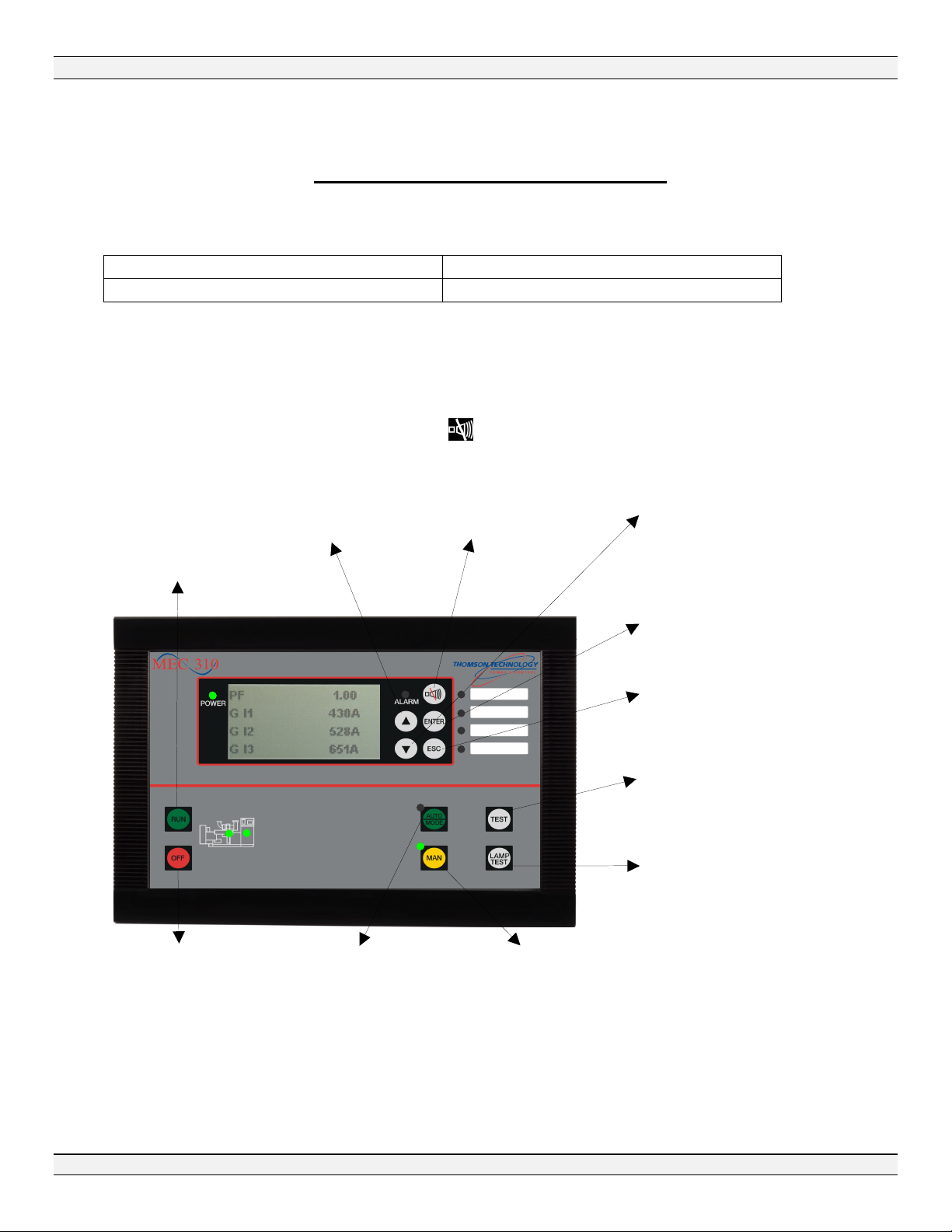
3. Push-buttons, LEDs and Display
Dimensions
Front dimensions H x W
Unit depth
Push-Button Functions - Island Controller
The push-buttons on the unit have the following functions:
160 x 220 mm (6.30” x 8.66”)
54 mm (2.13 “)
:
Permits local
engine Start/Run.
Operation Mode
must be in MAN
to enable this
Push-button.
▲:
Normal Display: Scrolls
the display up once.
Program Menu:
Increases set point
value.
:
Silences Local Horn and
resets horn relay output.
Hold for 2 seconds to
display alarm list.
▼:
Normal display: Scrolls the
display down once.
Program Menu: Decreases
set point value.
:
Enters value or
acknowledges alarm.
:
Escape\Exit from Parameter
Menu, Alarm Lists or Event
Logs to the Normal Display.
:
Activates the programmed timed
:
Activates all LEDs for
3 seconds.
:
Stops the engine
immediately.
If the unit is running in
AUTO, the operation
mode will change to
MAN and the engine
PM090 Rev 0 08/12/01 Thomson Technology
:
Automatic Operation
Mode selector.
Requires a Remote
Start Input to Initiate
Start/Run Sequence.
4
:
Manual Operation Mode
selector.
Requires RUN Push-button
be depressed to initiate
Page 6

MEC 310 OPERATION MANUAL
RUN: Permits local engine start and run. Mode Selection must be in MAN to enable this push-button.
OFF: Stops the engine instantaneously. If the unit is in AUTO mode, the mode will change to MAN and
the engine will immediately stop.
Note: For Shutdown fault clearing the OFF button must 1st be depressed before pressing the
ENTER button. If the condition is still present the shutdown is acknowledged and will self–clear
when the field device or programming logic permits a return to the none-fail state.
AUTO: AUTO running mode selector.
MAN: Manual Operation Mode selector. Requires RUN Push-button be depressed to initiate Start/Run
Sequence
TEST: Initiates the test sequence selected for the push-button. Test type only programmable using
TPS300 utility software.
LAMP TEST: Lamp test. One push will illuminate all LEDs for 3 seconds.
ESC: Escape\Exit from Parameter Menu, Alarm Lists, Event Logs or Fault Banner to the Normal
Display. Hides pop-up messages.
: Resets horn relay. Extra function: Press and hold button 2 sec. to see alarm list.
▲: Normal display: Scrolls the display up once. Programming: Increases set point value.
▼: Normal display: Scrolls the display down once. Programming: Decreases set point value.
ENTER: Enters value/acknowledges alarm.
PM090 Rev 0 08/12/01 Thomson Technology
5
Page 7

MEC 310 OPERATION MANUAL
Power LED
:
Alarm LED
Generator Voltage and Frequency OK
Additional alarm indication LEDs:
LED Functions
The LEDs provide the following status:
Flashing: Active, non-acknowledged alarm(s) present.
Steady: Active, acknowledged alarm(s) present.
Running feedback present
(selectable in program)
• Oil Pressure
• Magnetic Pickup
• DC Charging Alternator
• AC Voltage
• AC Frequency
• Illuminates after Voltage & Frequency
are within limit for programmed delay
(channel 6221)
Power: Power OK indicator.
Alarm LED: Flashing: Active, non-acknowledged alarm(s) present.
Steady: Active, acknowledged alarm(s) present.
Amber: Alarm only condition
Red: Shutdown condition present, alarm condition may be present but
shutdowns have higher precedent.
Additional alarm
Indication LEDs: Flashing: Active, non-acknowledged alarm(s) where output A or B is configured to
LED 1, 2, 3 or 4.
Steady: Active, acknowledged alarm(s) where output A or B is configured to LED
1, 2, 3 or 4.
:
LED on when the configured alarm
or condition is present
(For more information, see relay
configuration in the “Installation and
Operators Manual”).
LED ON – Auto Mode selected
LED ON – Manual Mode selected
Running Feedback: Provides crank disconnect or backup means and visual indication of engine running.
More than type one can be used at the same time.
Generator Volts/Hz Ok: Illuminates once generator voltage & frequency have been within acceptable
PM090 Rev 0 08/12/01 Thomson Technology
limits for a programmed period of time.
6
Page 8

MEC 310 OPERATION MANUAL
Utility Supply Status LED
GCB CLOSE
GCB Close Push
-
button
UCB Close Pu
sh-button
GCB Trip Push
-
button
UCB Trip Push
-
button
AMF Controller Option (Auto Mains Failure)
The AMF controller has the following push-buttons in addition to the those on the Island Controller:
The AMF breaker control push-buttons are only active in the Manual Operation Mode.
UCB = Utility Circuit
• Active only when the generator
voltage & Hz are within programmed
limits, associated delays expired and
USB close removed.
• Always active when in Manual
Operation Mode.
• Always active when the manual mode
is selected, not dependant on voltage
and Hz within programmed limits
GCB = Generator Circuit
Breaker
Breaker
• Always active when the manual mode is
selected, not dependant voltage & Hz
within programmed limits
AMF Status LEDs
LED illuminates (delay programmable - channel 6221)
The GCB and UCB breaker status LEDs are only illuminated when the breaker close output
contact is closed. When either of the trip push-button is depressed its associated the LED is
immediately extinguished.
PM090 Rev 0 08/12/01 Thomson Technology
, only permitted once Gen Volts & Hz Ok
7
Flashing Red LED = Utility out of limits
delay, inhibit engine start.
Solid Red LED = Utility out of limits
delay complete, engine start sequence
and transfer blocks removed.
Flashing Green LED = Utility healthy
and in Transfer Return Delay.
Solid Green LED = Utility healthy and
transfer to generator initiated or complete
Page 9

MEC 310 OPERATION MANUAL
AMF Push-button/LED Terms & Functions
GCB = Generator Circuit Breaker
UCB = Utility Circuit Breaker
GCB Trip: Generator or automatic transfer switch breaker trip/open push-button. This push-button is
always active when the Manual Operation Mode is selected.
GCB Close: Generator or automatic transfer switch breaker close push-button. This push-button is only
active if the generator is running, its voltage and frequency are within acceptable limits for the set delay
time as defined in programming and the USB Close has been removed (press UCB Trip to remove GCB
close inhibit condition).
UCB Trip: Utility or automatic transfer switch breaker trip/open push-button. This push-button is always
active when the Manual Operation Mode is selected.
UCB Close: Utility or automatic transfer switch breaker close push-button. This push-button is always
active when the Manual Operation Mode is selected. GCB close must be removed to permit operation.
Changing the operating mode from Manual to Auto will not cause opertional errors. Making this
change will only revert automatic breaker and generator control to the MEC 310. Mode changes
can be made at anytime, however if changing from Automatic to Manual all operational
sequences must be carried out manually. Automatic generator starting and transferring of
essential loads will not occur.
AMF LED Functions
GCB LED: Green LED illuminates when generator circuit breaker is closed.
UCB LED: Green LED illuminates when utility circuit breaker is closed.
Utility Supply Status LED: Provides at a glance health status of the utility supply, these are:
Flashing Red LED = Utility out of limits delay, inhibit engine start.
Solid Red LED = Utility out of limits delay complete, engine start sequence and transfer
blocks removed.
Flashing Green LED = Utility healthy and in Transfer Return Delay.
Solid Green LED = Utility healthy and transfer to generator initiated or complete
PM090 Rev 0 08/12/01 Thomson Technology
8
Page 10

MEC 310 OPERATION MANUAL
RPM
0
2 alarm(s)
Display Functions
The display indicates both analog readings and alarms messages. Illustrated below are examples:
MEC 310
HW 1.02
SW 1.20.5
Fuel level 80 %
Oil press 2.0 bar
Water 90°C
1 0 d 0 h
2 0 d 0 h
Run hours 24 h
Alarm list
2 alarm(s)
Controller type, Hardware and Software Version.
Various analog values can be displayed, shown are:
Fuel Level, Oil Pressure, Water Temp. & RPM.
Others values, which can be displayed, are: AC & DC
voltage, AC current, frequency, kW, kVA, kVAR & Power
Factor
Service Timer 1 and 2.
Run hours.
Press ENTER to enter the list of active alarms.
High Battery
Acknowledged
Parameter
D+ delay
0.0 s 10.0 s 100.0 s
Min. value Actual value Max. value
Active alarm list. The alarm list pops up automatically,
when an alarm appears. When the arrow is present, more
alarms are active. Press ▲or▼ to scroll through the list.
Exit the list by pressing ESC.
Press ENTER to gain access to the parameter setting
Menu.
Parameter example: D+ delay setting. Use ▲ or ▼ to
scroll through the settings list. If a change of settings is
necessary, press ENTER and enter the password. Then
use ▲ or ▼ to change values. Use ESC to leave
settings.
PM090 Rev 0 08/12/01 Thomson Technology
9
Page 11

Disclaimer
The Product is delivered with certain factory setting. The factory settings are based on typical
values and not to be considered acceptable for the equipment it is intended to operate and
protect. Thus precautions must be taken to confirm all settings meet the requirements of the
equipment being put into service.
Thomson Technology takes no responsibility for the installation or operation of the enginegenerator set controls. If there is any doubt about how to install or operate the engine-generator
set controlled by this unit, the company responsible for the installation or the operation of the
equipment must be contacted.
To better understand the programming and methods of programming please refer to the MEC310
Installation and Operation manual.
MEC 310 OPERATION MANUAL
4. Disclaimer
PM090 Rev 0 08/12/01 Thomson Technology
10
Page 12

MEC 310 OPERATION MANUAL
5. Basic Operation
Basic Operational Theory
The operation instructions provided are based on the assumption the controller has been
previously reviewed, programs modified and the controls and engine generator set
commissioned as acceptable for it’s intended use. It is also assumed the engine generator set
is ready to operate and all necessary house keeping has been completed such as, checking oil
and coolant levels, all mechanical and electrical fundamentals proven to be in good working
order.
Initial Power up and Fault Clearing
On initial power up of the controller it is probable that various alarms or shutdowns may be presented.
These will need to be cleared prior to placing the equipment into service or operation.
Fault alarms can only be cleared if the alarm message appears on the display, the field device causing
the fault has returned to the non-fail state or the associated alarm is programmed to be ignored during
initial start up (bypassed on start) and the ENTER push-button depressed. If the field device remains in
its fault state during the reset process and its fault condition is not programmed to be ignored during initial
start up pressing the ENTER push-button will only result in acknowledging the alarm.
Shutdown states require the OFF push-button be depressed prior to the ENTER push-button to
allow fault clearing. This ensures the engine generator set cannot unintentionally restart after the
fault is cleared if an automatic start is being requested.
Previously acknowledged alarms or shutdowns will clear automatically when its associate field
device returns to its non-fail state.
Shutdown conditions differ from Alarm conditions in that only one shutdown can exist at a time, 1st
shutdown in locks out subsequent shutdowns. If multiple shutdowns were permitted it would be
impossible to determine which state was the actual cause making troubleshooting a nearly impossible
task.
The controller provides a quick reference as to the alarm state level. The alarm LED on the controller can
change between an amber or red state. If both alarms and a shutdown are present the LED will be red
indicating the highest level of alarm, this being a shutdown condition. When there are only alarms
present, the alarm LED will be amber. Multiple alarms are permitted and will be displayed on the alarm
list with an up/down arrow advising to scroll through the list to view all. Only the displayed alarm can be
cleared, unviewed alarms cannot be cleared unless displayed or previously acknowledged.
A flashing alarm LED is an indication of a new alarm/shutdown, which is unacknowledged. Pressing the
ENTER push-button will acknowledge and/or clear the alarm if the associated field device or program
permits. If not permitted the alarm LED will change to a solid state, if multiple new alarms are present the
LED will continue to flash until all new alarms are acknowledged or cleared.
The Horn Silence push-button only silences the local controller horn and reset the horn relay
output, it will not acknowledge or clear alarm states. The MEC310 internal alarm horn must be
enabled using M-Logic if desired.
The Horn Silence push-button provides a secondary function, by holding this push-button for
greater than 2 seconds the alarm list is displayed.
PM090 Rev 0 08/12/01 Thomson Technology
11
Page 13

MEC 310 OPERATION MANUAL
Manual Operation Mode
Pressing either the MAN or OFF push-buttons will select Manual Operation Mode.
In the Manual Operation Mode the remote start input is ignored, starting and stopping of the engine
generator can only be achieved with the RUN and OFF push-buttons on the left side of the controller.
Once a manual RUN is initiated the engine generator set will continue to operate until manually
requested to stop by pressing the OFF push-button (immediately stops without cooldown) or by
pressing the AUTO push-button (the cooldown sequence will be initiated prior to the engine
stopping), the fuel supply blocked/exhausted or a shutdown action resulting from a protection
setting.
With the Manual Operation mode selected, pressing the RUN push-button initiates the start sequence.
The start sequence is as follows:
1. Preheat delay is posted if programmed (also pre-start delay for preheat, prelube, etc…)
2. Initiate starter motor engagement and cranking of engine.
3. Disengages the starter motor automatically once the speed of the engine rises above the run
setpoint. Additional crank and rest cycles are added if the engine fails to start in its first attempt.
Fail to Start shutdown protection is activated should the engine not start after the programmed
number of attempts has been exceeded.
4. All protection and alarm functions, which were bypassed when not running, are enabled after the
engine starts (generally within 10 – 20 seconds of the starter motor being disengaged).
5. Engine generator set continues to operate until requested to stop.
The stop sequence is as follows:
1. Press the OFF push-button. The engine generator set stops immediately without a cooldown
sequence.
2. Press the AUTO push-button. The engine generator continues to operate and will include a
cooldown sequence before stopping the engine generator set. The stop/cooldown sequence is
not initiated until the remote start input is removed.
Automatic Operation Mode
Pressing the AUTO push-button selects Automatic Operation Mode.
The start sequence is as follows:
1. When a remote start contact is closed to a binary input configured for remote start the Preheat
delay is posted (if programmed).
2. Initiates starter motor engagement and cranking of engine
3. Disengages the starter motor automatically once the speed of the engine rises above the run
setpoint. Additional crank and rest cycles are added if the engine fails to start in its first attempt.
Fail to Start shutdown protection is activated should the engine not start after the programmed
number of attempts has been exceeded.
4. All protection and alarm functions, which were bypassed when not running, are enabled after the
engine starts (generally within 10 – 20 seconds of the starter motor being disengaged).
5. The engine generator set will continue to operate until requested to stop.
The stop sequence is as follows:
1. When the remote start contact opens the engine generator set will continue to operate for it’s
programmed cooldown period and then stop.
PM090 Rev 0 08/12/01 Thomson Technology
12
Page 14

MEC 310 OPERATION MANUAL
AMF - Manual Operation (optional feature)
Pressing either the MAN or OFF push-buttons selects Manual Operation Mode and enables the AMF
breaker control push-buttons.
The start sequence for the generator is covered under manual operation mode as previously described.
The following describes the AMF operation utilizing the push-buttons provided:
1. With the engine generator set operational and producing acceptable voltage and frequency the
generator volts/frequency ok LED will illuminate after a programmed time delay
(programmable in TPS300 - channel 6221). Once the V/Hz Ok LED lights and the UCB Trip is
given the GCB close push-button inhibit is removed and the GCB Close push-button becomes
operational.
2. Press the UCB Trip push-button to release the UCB and enable the GCB Close push-button.
This action may move the transfer mechanism to the off/open state or have no effect (operation
will vary based on logic design).
3. Press the GCB Close push-button. This will move the essential load from the utility/mains
supply to the generator supply. Note: The GCB LED may light prior to the breaker closing if
switch position indication is not used, typically no breaker position feed back is incorporated and
the LED follows the output contact action (breaker auxiliary contacts can be monitored, in this
case the LEDs will follow the breaker action).
4. The transfer mechanism will remain in this position even if the generator stops for any reason.
The stop sequence is as follows:
1. Press the GCB Trip push-button. This releases the GCB breaker and enables the UCB Close
push-button.
2. Press the UCB Close push-button. The transfer mechanism will open the generator breaker
and close the utility/mains breaker.
3. To stop the generator press OFF after the generator has operated without load for a
reasonable period of time. Alternatively the Auto Operation Mode can be selected by pressing
AUTO. With the load on the utility/mains and within proper limits the engine cooldown will be
initiated, the generator will continue to run until the cooldown timer expires then stop.
AMF - Automatic Operation
Pressing the AUTO Mode push-button selects Automatic Operation Mode; in Auto Operation Mode the
AMF breaker control push-buttons are disabled.
The basic start/stop sequence for the generator is covered under automatic operation mode as
previously described, the only exception is, the AMF feature starts and stops the engine generator set
based on monitoring of the utility/main sensing voltage.
The following describes the automatic AMF operation:
1. On detection of utility/mains out of limits the engine generator starts, once producing acceptable
voltage and frequency for a period of time as defined in program the generator volts/frequency
ok LED will illuminate. (V/Hz delay time is programmable only using TPS300 software - channel
6221).
PM090 Rev 0 08/12/01 Thomson Technology
13
Page 15

MEC 310 OPERATION MANUAL
2. Once the V/Hz Ok LED illuminates the UCB Closed LED will extinguish and the GCB Closed LED
will illuminate. This is the indication the transfer mechanism is in transition or transferred to the
generator supply.
Note: Breaker auxiliary contacts can be added to permit the LED indicators to only illuminate
once the breaker closes.
3. The MEC 310 will maintain generator operation until the load is retransferred to the utility/mains.
4. When the utility/mains voltage returns within acceptable limits the retransfer to utility/mains is
inhibited is maintained until the transfer return delay timer has expired. This ensures the load is
not returned to an unstable supply. Once the transfer return timer expires, the GCB close is
removed and the UCB close permit given.
5. The transfer mechanism moves the essential load from the generator supply to the utility/mains
supply.
6. Once the load transfer has occurred the generator continues to run for the programmed cooldown
time then stops.
THOMSON TECHNOLOGY reserves the right to change any of the above.
PM090 Rev 0 08/12/01 Thomson Technology
14
 Loading...