

Page 1
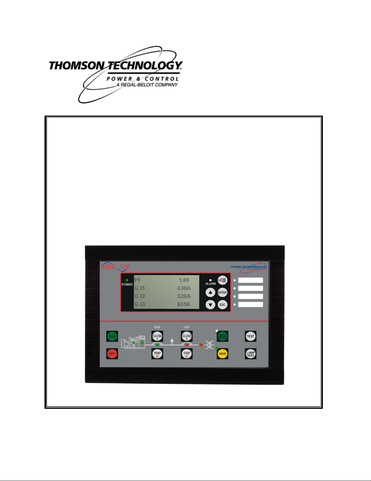
MEC 310
APPLICATION NOTES
FEATURE (EXP)
External I/O modules
r. 0524B
PM0104 Rev 0 09/08/20
9087A – 198th Street, Langley, BC Canada V1M 3B1 Telephone (604) 888-0110
Telefax (604) 888-3381 E-Mail: info@thomsontechnology.com www.thomsontechnology.com
Page 2

This description of options covers the following products:
MEC 310 SW version 1.2X.X
Page 3

Table of Contents
MEC 310 APPLICATION NOTES - External I/O Modules
1. WARNINGS AND LEGAL INFORMATION .................................................................................... 1
EGAL INFORMATION AND RESPONSIBILITY
L
LECTROSTATIC DISCHARGE AWARENESS
E
AFETY ISSUES
S
ACTORY SETTINGS
F
EFINITIONS
D
2. DESCRIPTION OF OPTION .............................................................................................................. 2
EATURE
F
MEC 310
NSTALLATION OF BECKHOFF CONTROLLER (BUS COUPLER
I
3. FUNCTIONAL DESCRIPTION .......................................................................................................... 5
UPPORTED MODULES
S
UNCTIONAL CHECK OF EXTERNAL
F
4. PARAMETER LIST.............................................................................................................................. 9
OMMUNICATION SETUP
C
XTERNAL
E
5. FAULT FINDING ................................................................................................................................. 12
IAGNOSTIC
D
.............................................................................................................................................1
...................................................................................................................................... 1
.................................................................................................................................................1
EXP .............................................................................................................................................. 2
INTERFACE
I/O
LEDS..................................................................................................................................... 13
................................................................................................................................... 2
.................................................................................................................................. 5
I/O
............................................................................................................................... 9
SETUP
................................................................................................................................. 10
.................................................................................................. 1
....................................................................................................1
).........................................................................3
MODULES
........................................................................................ 6
PM104 R0 09/08/20 THOMSON TECHNOLOGY
Page 4
MEC 310 APPLICATION NOTES - External I/O Modules
The notes provide general information, which will be helpful for the reader to
ly dangerous situation, which could result in
lines are not
currents and voltages. Do not touch any AC
1. Warnings and legal information
Legal information and responsibility
Thomson Technology takes no responsibility for installation or operation of the generator set. If there
is any doubt about how to install or operate the engine controlled by the unit, the company responsible
for the installation or the operation of the set must be contacted.
The units are not to be opened by unauthorized personnel. If opened anyway, the
Electrostatic discharge awareness
Sufficient care must be taken to protect the terminals against static discharges during the
installation. Once the unit is installed and connected, these precautions are no longer necessary.
Installing the unit implies work with dangerous currents and voltages. Therefore, the installation should
only be carried out by authorised personnel who understand the risks involved in working with live
electrical equipment.
Be aware of the hazardous live
measurement inputs as this could lead to injury or death.
warranty will be lost.
Safety issues
Factory settings
The unit is delivered with certain factory settings. Given the fact that these settings are based on
average values, they are not necessarily the correct settings for matching the individual engine.
Thus precautions must be taken to check the settings before running the engine.
Definitions
Throughout this document a number of notes and warnings will be presented. To ensure that these
are noticed, they will be highlighted in order to separate them from the general text.
Notes
Warning
bear in mind.
The warnings indicate a potential
death, personal injury or damaged equipment, if certain guide
followed.
PM104 R0 09/08/20 Page 1 THOMSON TECHNOLOGY
Page 5
MEC 310 APPLICATION NOTES - External I/O Modules
cia.com to download a detailed
Wiring details: Please refer to the document ‘Installation Instructions and
2. Description of option
Feature EXP
EXP is a CANbus based serial interface for external I/O controllers. This option gives the possibility
to add more inputs and outputs to MEX 310 controllers via the CANbus.
MEC 310 controllers support the CANopen protocol. This protocol is based on the CANopen
Application Layer and Communication Profile Specification CiA Draft Standard 301 Version 4.02. It
is not the purpose of this document to describe all the functionalities of the CANopen
communication. The CANopen is implemented and runs according to the CANopen standards and
needs no special attention from the user.
Please use the website http://www.canexplanation of the CANopen description.
MEC 310 interface
Reference Handbook’.
Terminal description
The CAN #2 terminals 57(H) and 59(L) are also used for EAP 300 (see feature EAP 300).
Terminals Function Description
57 CAN-H
58 CAN-GND
59 CAN-L
CAN #2: Terminals for CAN
communication
PM104 R0 09/08/20 Page 2 THOMSON TECHNOLOGY
Page 6

MEC 310 APPLICATION NOTES - External I/O Modules
MEC 310: Please refer to the document ‘Installation Instructions and
Communication fault: In case any LEDs on the Beckhoff controller are
flashing continuously for more than 5s, please refer to the chapter ‘Fault
Installation of Beckhoff controller (bus coupler)
The following is a step-by-step guide to set up the communication between the MEC 310 unit and
the Beckhoff modules.
Beckhoff controller setup
CANbus wiring
Documentation regarding Beckhoff modules can be found at www.beckhoff.com.
1. Set the Baud rate to ‘AUTO’.
2. Set the Node ID to a value between 10 and 64.
3. Connect the required I/O modules to the controller.
4. Mount the ‘End Bus Terminal’: KL9010 module.
5. Disconnect power to the MEC 310 and the Beckhoff controller.
6. Connect the CANbus wires to the Beckhoff controller according to the ‘Installation
Instructions’.
Reference Handbook’.
MEC 310 unit
7. Connect power to the MEC 310 unit and the Beckhoff controller.
8. Set CAN1 type (menu 7971 = H8.2 or menu 7981 = H8.8) to 'Beckhoff comm.'.
9. Set the Baud rate (default: 125kbit/s).
10. Set the Node ID (menu 7973/7983) to the same value as selected on the Beckhoff
11. Communication between the MEC 310 unit and the Beckhoff controller is now established.
MEC 310: Menu 7971 and 7981 are not available.
MEC 310: The Baud rate is fixed at 50kbit/s.
controller.
MEC 310: Menu 7973 is not available.
finding’ in this document.
PM104 R0 09/08/20 Page 3 THOMSON TECHNOLOGY
Page 7

MEC 310 APPLICATION NOTES - External I/O Modules
12. To see the available external I/Os, retrieve the parameters from the MEC 310 unit with the
TPS 300 software.
13. Click on ‘External I/O’ in the TPS 300 software to see or change settings for external I/O
modules.
PM104 R0 09/08/20 Page 4 THOMSON TECHNOLOGY
Page 8

MEC 310 APPLICATION NOTES - External I/O Modules
Detailed specification of the Beckhoff modules can be found at the website
3. Functional description
Supported modules
The MEC 310 supports communication with the Beckhoff CANopen I/O modules. The following
CANopen modules are available from Thomson Technology:
Controller (bus coupler) – MANDATORY COMPONENT
Type Numbers of I/Os supported by MEC 310
EXP-BM (BK5150) 8 analogue inputs, 8 analogue outputs, 16 digital inputs and 16
digital outputs
Analogue Input Modules – Order as required
EXP-AI4 (KL3444) 4-ch. analog input terminals 0…20 mA
Digital Input Modules – Order as required
EXP-I4 (KL1104) 4-ch. digital input terminals 24 V DC
EXP-I8 (KL1408) 8-ch. digital input terminals 24 V DC
EXP-I16 (KM1002) 16-ch. digital input 24 V DC
Digital Output Modules – Order as required
EXP-O4 (KL2114) 4-ch. digital output terminals 24 V DC/0.5A
EXP-O8 (KL2408) 8-ch. digital output terminals 24 V DC/0.5A
EXP-O16 (KM2002) 16-ch. digital output 24 V DC/0.5A
End Bus Terminal – MANDATORY COMPONENT
EXP-EBT (KL9010) End bus terminal
Contact Thomson Technology for information on other modules.
www.beckhoff.com.
BK5150
MANDATORY
PM104 R0 09/08/20 Page 5 THOMSON TECHNOLOGY
KL1104 KL1408 KM1002 KL2114 KL2408 KM2002 KL3444
ORDER AS REQUIRED
LK9010
MANDATORY
Page 9

MEC 310 APPLICATION NOTES - External I/O Modules
Functional check of external I/O modules
Alarm messages in display
Alarm message Description
Ext. I/O unk. module The module used is not supported by the MEC 310 unit.
Ext. I/O new setup If modules are changed or have changed place in the row of
modules, this error message will be active. Can be removed by reset
in menu 7974 ‘Reset’.
Module check
The module check can only take place using the TPS 300 software.
Modules are presented in the order by which they are mounted, counting from the CANbus controller
side.
External I/Os will only be shown in the TPS 300 software if they are present.
The result of the check can be read in status channels 12950-12983.
The Beckhoff module transmits a status message to the unit. This message is a HEX value for digital
I/O units and decimal for controllers/analogue I/O units.
PM104 R0 09/08/20 Page 6 THOMSON TECHNOLOGY
Page 10

Digital I/O
MEC 310 APPLICATION NOTES - External I/O Modules
1. digit: 8 for digital
2. digit: Number of input/output (2, 4 or 8)
3. digit: Not used (0)
4. digit: Input [1] or output [2]
In the TPS 300 software, all values are presented as decimal values, so the HEX values for the
digital I/O modules are translated as follows:
Inputs:
0x8201h = -32255d
0x8401h = -31743d
0x8801h = -30719d
Outputs:
0x8202h = -32254d
0x8402h = -31742d
0x8802h = -30718d
PM104 R0 09/08/20 Page 7 THOMSON TECHNOLOGY
Page 11

MEC 310 APPLICATION NOTES - External I/O Modules
The module check is only carried out when resetting the communication
Examples for digital I/O modules
Module Hex value Dec value
EXP-O4 (KL2114) 8402 -31742
EXP-O8 (KL2408) 8802 -30718
EXP-I16 (KM1002) 8201 -32255
EXP-I4 (KL1104) 8401 -31743
Analogue I/O
A 4-digit decimal value is presented.
This number represents the module version used.
Examples for analogue I/O modules
Module Value
EXP-AI4 (KL3444) 3204
(parameter 7974 or 7984).
PM104 R0 09/08/20 Page 8 THOMSON TECHNOLOGY
Page 12

MEC 310 APPLICATION NOTES - External I/O Modules
uploaded again.
4. Parameter list
Communication setup
7940 CAN2 comm error
No. Setting Min.
setting
7941 CAN2 comm error Delay 2.0 s 600.0 s 10.0 s
7942 CAN2 comm error Relay output A Not used R0 (none)
7943 CAN2 comm error Relay output B Not used
7944 CAN2 comm error Enable OFF ON OFF
7980 CAN2
No. Setting Min.
setting
7981 CAN2 Type OFF
EAP-2
Beckhoff
7982 CAN2 Baud 50 k
125 k
250 k
7983 CAN2 ID 10 64 1
7984 CAN2 Reset NO YES NO
MEC 310: Menu 7981 and 7982 are not available.
Menu 7984 is for re-establishing communication after a fault/disconnection.
After changing type, the parameter list in the TPS 300 software must be
Max.
setting
Option
dependent
Max.
setting
Factory
setting
R0 (none)
Factory
setting
OFF
125 k
7950 KL320x config
No. Setting Type
7951 KL320x config Module 1
7952 KL320x config Module 2
7953 KL320x config Module 3
7954 KL320x config Module 4
PM104 R0 09/08/20 Page 9 THOMSON TECHNOLOGY
The above selections for KL3202/3204 cannot be changed.
After changing module type, the parameter list in the TPS 300 software must be
uploaded again.
PT100 (2/3-wire)
PT1000 (2/3-wire)
10-3200 ohm (2-wire)
10-1200 ohm (2-wire)
Factory
setting
PT100
(2/3-wire)
Page 13

MEC 310 APPLICATION NOTES - External I/O Modules
The external analogue outputs are used as transducer outputs in menu 5820 to
External I/O setup
Analogue inputs
12000 Ext. an. in 1.1
No. Setting Min.
setting
12000 Ext. an. in 1.1
12010 Ext. an. in 1.2
No. Setting Min.
12010 Ext.an. in 1.2
Same order for settings 12030-12230.
Set point -20000 20000 10
Delay 2.0 s 600.0 s 10.0 s
Fail class MEC 310 unit dependent Warning
Relay output A Not used Not used
Relay output B Not used
Enable OFF ON OFF
setting
Set point -20000 20000 10
Delay 2.0 s 600.0 s 10.0 s
Fail class MEC 310 unit dependent Warning
Relay output A Not used Not used
Relay output B Not used
Enable OFF ON OFF
Max.
setting
Option
dependent
Max.
setting
Option
dependent
Factory
setting
Not used
Factory
setting
Not used
Analogue outputs
5970. Please refer to the description of option E+F.
MEC 310 does not support analogue outputs.
PM104 R0 09/08/20 Page 10 THOMSON TECHNOLOGY
Page 14

MEC 310 APPLICATION NOTES - External I/O Modules
Digital inputs
12540 Ext. dig. in 1
No. Setting Min.
setting
12540 Ext. dig. in 1
Delay 2.0 s 600.0 s 10.0 s
Fail class MEC 310 unit dependent Warning
Relay output A Not used Not used
Relay output B Not used
Enable OFF ON OFF
Same order for settings 12560-12690.
Digital outputs
Max.
setting
Option
dependent
Factory
setting
Not used
12790 Ext. dig. out 1
No. Setting Min.
setting
12790 Ext digital output 1
Delay 2.0 s 600.0 s 10.0 s
Fail class MEC 310 unit dependent Warning
Relay output A Not used Not used
Relay output B Not used
Enable OFF ON OFF
Same order for settings 12810-12940.
Max.
setting
Option
dependent
Factory
setting
Not used
PM104 R0 09/08/20 Page 11 THOMSON TECHNOLOGY
Page 15

MEC 310 APPLICATION NOTES - External I/O Modules
5. Fault finding
Beckhoff controllers
LC5100 BK5120
BK5150
PM104 R0 09/08/20 Page 12 THOMSON TECHNOLOGY
Page 16

MEC 310 APPLICATION NOTES - External I/O Modules
Diagnostic LEDs
The Beckhoff controllers have LEDs for display of status. They can be used for fault finding.
CAN ERR blink code
CAN ERR Meaning
Off
Fast blinking
(Approx. 50ms on, approx. 50ms off;
alternating with RUN LED).
1 x flash
(Approx. 200ms on, 1s off).
2 x blinking
(Each approx. 200ms on, 200ms off, followed
by a 1s pause).
3 x blinking
(Each approx. 200ms on, 200ms off, followed
by a 1s pause).
4 x blinking
(Each approx. 200ms on, 200ms off, followed
by a 1s pause).
CANbus
has no errors
Automatic Baud rate detection has
found a valid Baud rate
.
not yet
. Not enough
telegrams on the bus yet.
CAN warning limit exceeded.
There are too
many error frames on the bus. Please check
the wiring (e.g. termination resistors, screens,
conductor length, stubs). Other possible
causes for exceeding the warning limit: There
are no other participating devices in the
network (occurs e.g. when the first node is
started).
The
guarding or heartbeat monitor
alerted, because neither guarding telegrams
nor heartbeat telegrams are received.
Precondition for guarding monitoring: Guard
time and life time factors are > 0.
Precondition for heartbeat monitoring:
Consumer heartbeat > 0).
The bus coupler is pre-operational (PDOs
switched off), and the outputs are in the error
state.
A
synchronisation error
has occurred. No
sync. telegrams have been received during the
set monitoring time (object 0x1006 x 1.5). The
bus node is pre-operational (PDOs switched
off), and the outputs are in the error state.
Event timer error
: The bus coupler has not
received an RxPDO within the set event time
(0x1400ff sub-index 5). The bus node is preoperational (PDOs switched off), and the
outputs are in the error state.
has
RUN blink code
RUN Meaning
Off
Firmware status < C0: Bus node is in
. No communication is possible with SDO
state
stopped
or PDO.
Fast blinking
(Approx. 50ms on, approx. 50ms off;
alternating with CAN ERR LED).
1 x blinking
(Approx. 200ms on, 1s off).
Blinking cyclically
(Approx. 200ms on, 200ms off).
On
PM104 R0 09/08/20 Page 13 THOMSON TECHNOLOGY
Automatic Baud rate detection has
found a valid Baud rate
. Not enough
not yet
telegrams on the bus yet.
Bus node is in
stopped state
. No
communication is possible with SDO or PDO.
Bus node is in
pre-operational state
. The
node has not yet started.
Bus node is in
operational state
.
Page 17

MEC 310 APPLICATION NOTES - External I/O Modules
Tx overflow blink code
Tx overflow Meaning
On
A
transmit queue overflow
The bus coupler could not send its messages.
Cause: E.g. excessive bus loading. A bus
coupler reset must be carried out.
Blinking cyclically
(Approx. 200ms on, 200ms off).
Logical Tx queue overflow: SYNC interval too
short. The coupler could not deliver all the
TxPDOs before the following SYNC telegram.
The TxPDOs are then e.g. delivered in every
second SYNC interval.
Remedy: Lengthen the SYNC interval or raise
the transmission type. In some cases it may be
appropriate to reduce the I/O count at this bus
station (e.g. by moving I/Os to the
neighbouring station).
Note: The logical Tx queue overflow is
signalled for approx. 10s and then reset. If it
keeps recurring, signalling is maintained.
has occurred.
Rx overflow blink code
Rx overflow Meaning
On
A
receive queue overflow
has occurred. The
bus coupler loses messages.
Cause: E.g. bursts of short telegrams.
A bus coupler reset must be carried out.
Blinking cyclically
(Approx. 200ms on, 200ms off)
A
receive queue overflow
has occurred. The
bus coupler has lost messages, but the
overflow condition is no longer current.
Cause: E.g. bursts of short telegrams, perhaps
during a status transition (e.g. very short
SYNC interval during transition after
operational).
Signalling is reset during a bus coupler reset.
K-bus LEDs (local errors)
Two LEDs, the K-bus LEDs, indicate the operational state of the bus terminals and the connection
to these bus terminals. The green LED (I/O RUN) lights up in order to indicate fault-free operation.
The red LED (I/O ERR) flashes with two different frequencies in order to indicate an error. The
errors are displayed in the blink code in the following way:
Blink code
Fast blinking Start of the error code
First slow sequence
Second slow sequence
Error code
Error argument (error location)
PM104 R0 09/08/20 Page 14 THOMSON TECHNOLOGY
Page 18

MEC 310 APPLICATION NOTES - External I/O Modules
Continuous
Error type
Error code Error code
Description
Remedy
argument
General K-bus error - Check terminal strip.
flashing
1 pulse
0 EEPROM check sum error
1 Inline code buffer overflow
2 Unknown data type
- Set manufacturer’s setting with the
KS2000 software.
- Connect fewer terminals; too many
entries in the table for the
programmed configuration.
- Software update required for the
coupler.
2 pulses
0 Programmed configuration
incorrect table entry/bus
coupler
- Check programmed configuration for
correctness.
- Incorrect table entry/bus coupler.
(n>0) Incorrect table comparison
(terminal n)
3 pulses
0 K-bus command error - No terminal connected; attach
terminals.
- One of the terminals is defective;
halve the number of terminals
attached and check whether the
error is still present with the
remaining terminals. Repeat until the
defective terminal is located.
4 pulses
0
n
K-bus data error, break
behind bus terminal n
- Check whether the n+1 terminal is
correctly connected; replace if
necessary.
- Check whether the end terminal
9010 is connected.
5 pulses
n K-bus error during register
- Replace terminal n.
communication with
terminal
7 pulses
n BK5110 or LC5110:
Unsupported terminal
- Only use digital terminals or bus
coupler BK5120.
detected at location n
All information regarding error codes is related to the documentation from:
http://www.beckhoff.com/
Thomson Technology reserves the right to change any of the above
PM104 R0 09/08/20 Page 15 THOMSON TECHNOLOGY
 Loading...