

Page 1
SERVICE MANUAL
DOCUMENTATION TECHNIQUE
TECHNISCHE DOKUMENTATION
DOCUMENTAZIONE TECNICA
DOCUMENTACION TECNICA
No copying, translation, modification on other use authorized. All rights reserved worldwide. • Tous droits de reproduction, de traduction, d'adaptation et d'exécution réservés pour tous les pays. • Sämtliche Urheberrechte an diesen Texten und Zeichnungen stehen uns zu. Nachdrucke,
Vervielfältigungen - auch auszugsweise - nur mit unserer vorherigen Zustimmung zulässig. Alle Rechte vorbehalten. • I diritti di riproduzione, di traduzione, e esecuzione sono riservati per tutti i paesi. • Derechos de reproduccion, de traduccion, de adaptacion y de ejecucion reservados para todos los paises.
WARNING : Before servicing this chassis please read the safety recommendations.
ATTENTION : Avant toute intervention sur ce châssis, lire les recommandations de sécurité.
ACHTUNG : Vor jedem Eingriff auf diesem Chassis, die Sicherheitsvorschriften lesen.
ATTENZIONE : Prima di intervenire sullo chassis, leggere le norme di sicurezza.
IMPORTANTE : Antes de cualquier intervención, leer las recomendaciones de seguridad.
Code : 35884160 -0105 / 4,8M - DTH8040 Print.
VIDEO
DTH8040
DTH8040E
DTH8040U
Page 2
Indicates critical safety components, and identical components should be used for replacement. Only then can the
operational safety be garanteed.
Le remplacement des éléments de sécurité (repérés avec le symbole ) par des composants non homologués selon la
Norme CEI 65 entraine la non-conformité de l'appareil. Dans ce cas, la responsabilité du fabricant n'est plus engagée.
Wenn Sicherheitsteile (mit dem Symbol gekennzeichnet) nicht durch Original - Ersatzteile ersetzt werden, erlischt die
Haftung des Herstellers.
La sostituzione dei componenti di sicurezza (evidenziati con il segno ) con componenti non omologati secondo la
norma CEI 65 comporta la non conformitá dell'apparecchio. In tal caso è "esclusa la responsabilità " del costruttore.
La sustitución de elementos de seguridad (marcados con el simbolo ) por componentes no homologados segun la
norma CEI 65, provoca la no conformidad del aparato. En ese caso, el fabricante cesa de ser responsable.
MEASUREMENT CONDITIONS - CONDITIONS DE MESURES - MESSBEDINGUNGEN
CONDIZIONI DI MISURA - CONDICIONES DE MEDIDAS
RICEVITORE :
In UHF, livello d'entrata 1 mV, monoscopio barre :
- PAL, norma G. bianco 100%.
Via SCART, livello d'entrata 1 Vpp, monoscopio barre :
Colore, Contrasto, Luminositá media, Suono minimo.
Programma selezionato PR 01.
Tensioni continue rilevate rispetto alla massa con un voltmetro digitale.
RECEIVER :
On UHF,input level : 1 mV, bar test pattern :
- PAL, I standard, 100% white.
Via the scart socket, input level : 1 Vpp, bar test pattern :
Colour, contrast and brightness at mid-position, sound at minimum.
Programme selected : PR 01.
DC voltages measured between the point and earth using a digital
voltmeter.
EMPFÄNGER :
Bei UHF Eingangspegel 1 mV, Farbbalken :
- PAL, Norm G, Weiss 100%.
Über die Scartbuchse : Eingangspegel 1 Vss, Farbbalken :
Farbe, Kontrast, Helligkeit in der Mitte des Bereichs, Ton auf Minimum.
Zugeordnetes Programm PR 01.
Gleichspannungen mit einem digitalen Voltmeter zur Masse gemessen.
RECEPTEUR :
En UHF, niveau d'entrée 1 mV mire de barres
- SECAM, Norm L, Blanc 100%.
Par la prise Péritélévision, niveau d'entrée 1 Vcc, mire de barres .
Couleur, contraste, lumière à mi-course, son minimum.
Programme affecté PR 01.
Tensions continues relevées par rapport à la masse avec un
voltmètre numérique.
RECEPTOR :
En UHF, nivel de entrada 1 mV, mira de barras :
- PAL, norma G, blanco 100%.
Por la toma Peritelevision, nivel de entrada 1 Vpp mira de barra.
Color, Contraste, luz a mitad de carrera, Sonido minimo.
Programa afectado PR 01.
Tensiones continuas marcadas en relacion a la masa con un voltimetro digital.
MAIN
FRANÇAIS ESPAÑOLDEUTSCHENGLISH ITALIANO
1
2
3
4
5
6
7
8
9
10
11
12
13
14
15
16
17
18
19
20
21
NC
21
17
19
15
13
20
18
16
14
12
11
9
10
8
7
5
3
1
6
4
2
NC
AUDIO "R"
AUDIO "R"
AUDIO "L"
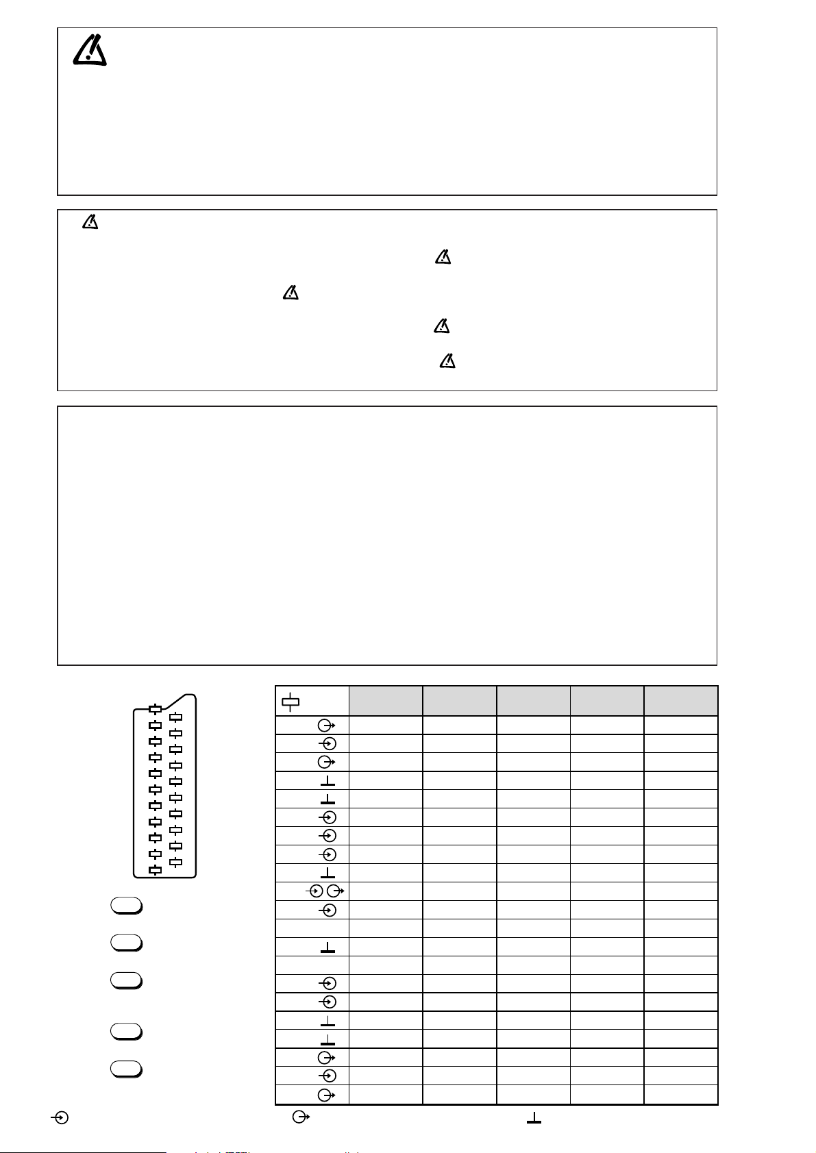
NOTE :
... etc. identifies each
pcb module.
AUDIO "D"
AUDIO "D"
AUDIO "G"
AUDIO
"BLEU"
AUDIO "G" MONO
"BLEU"
COMMUT. LENTE
"VERT"
"VERT"
"ROUGE"
COMMUT. RAPIDE
COMMUT. RAPIDE
VIDEO
VIDEO SYNCHRO
BLINDAGE PRISE
AUDIO "R"
AUDIO "R"
AUDIO "L"
AUDIO
"BLAU"
AUDIO "L" MONO
"BLAU"
AV
UMSCHALTUNG
"GRÜN"
"GRÜN"
"ROT"
AUSTASTUNG
AUSTASTUNG
VIDEO
VIDEO ODER
SYNCHRO
ABSCHIRMUNG
DES STECKERS
AUDIO "D"
AUDIO "D"
AUDIO "I"
AUDIO
"AZUL"
AUDIO "I" MONO
AZUL
"CONMUTACION
LENTA"
"VERDE"
"VERDE"
"ROJA"
"CONMUTACION
RAPIDA"
"CONMUTACION
RAPIDA"
VIDEO
VIDEO O SINCRO
BLINDAJE
DEL ENCHUFE
AUDIO "D"
AUDIO "D"
AUDIO "S"
AUDIO
"BLU"
AUDIO "S" MONO
BLU
"COMMUTAZIONE
LENTA"
"VERDE"
"VERDE"
"ROSSO"
"COMMUTAZIONE
RAPIDA"
"COMMUTAZIONE
RAPIDA"
VIDEO
VIDEO O SINCRO
INVOLUCRO METAL-
LICO DELLA PRESA
AUDIO "L" MONO
"BLUE"
"GREEN"
AV LINK AV LINK AV LINK AV LINK AV LINK
"GREEN"
"RED"
"ROUGE" "ROT" "ROJA""ROSSO""RED"
SLOW SWITCH
FAST SWITCH
VIDEO
VIDEO VIDEO VIDEOVIDEOVIDEO
PLUG SCREEN
BOX
VIDEO OR "SYNC"
FAST SWITCH
AUDIO
"BLUE"
: OUTPUT - SORTIE - AUSGANG - USCITA - SALIDA •
: EARTH - MASSE - MASSE - MASSA - MASA
MAIN
NOTE :
... etc. repères des
platines constituant l'appareil.
MAIN
NOTA :
... etc. marcas de las
placas que constituyen el
aparato.
MAIN
NOTA :
... ecc. sigla delle
piastre dell' apparecchio.
MAIN
HINWEIS :
... usw. Kennzeichnung
der Platinen, aus denen das
Gerät zusammengesetzt ist.
: INPUT - ENTRÉE - EINGANG - ENTRATA - ENTRADA •
Do not disconnect modules when they are energized!
Repairs on power supply section are to be carried out only with isolating transformer.
Ne pas retirer les modules lorsqu' ils sont sous tension. N'effectuer les travaux de maintenance sur la partie reliée
au secteur (Switch Mode) qu'au travers d'un transformateur d'isolement.
Module nicht bei eingeschaltetem Gerät entfernen!
Servicearbeiten am Netzteil nur unter Verwendung eines Regeltrenntrafos durchführen.
Non scollegare le piastre quando sono alimentate!
Per le riparazioni sulla sezione alimentatore, utilizzare un trasformatore isolatore.
No desconectar los módulos cuando están activados. Las reparaciones en la sección de alimentación de energía
deben ser ejecutadas solamente con un transformador de separación.
Page 3

DTH8005
First issue 12/ 04 3
SOMMAIRE
Page
CARACTERISTIQUES TECHNIQUES . . . . . . . . . . . . . . . . .4
PROCEDURE DE REGLAGES . . . . . . . . . . . . . . . . . . . .7 - 8
SCHEMA D' INTERCONNEXION . . . . . . . . . . . . . . . . .9 - 10
SCHEMA DES CIRCUITS D’ALIMENTATIONS . . . . . .11 - 12
SCHEMA DES CIRCUITS COMMANDES . . . . . . . . . .13 - 14
PLATINE PRISES CASQUE / NAVICLICK . . . . . . . . . .15 / 16
SCHEMA DE L’INTERFACE PERITELEVISION . . . . . . .17 - 28
SCHEMA DE LA PLATINE PRINCIPALE . . . . . . . . . . .29 - 46
Page
CIRCUIT IMPRIME DE L’ALIMENTATION . . . . . . . . .47 - 48
CIRCUITS IMPRIMES PLATINES COMMANDES . . . . .49 - 50
PLATINE INTERFACE PERITELEVISION . . . . . . . . . .51 - 54
CIRCUIT IMPRIME PLATINE PRINCIPALE . . . . . . . .55 - 58
ABREVIATIONS . . . . . . . . . . . . . . . . . . . . . . . . . .59 - 61
CONTENTS
Page
TECHNICAL DATA . . . . . . . . . . . . . . . . . . . . . . . . . . . . . .4
ADJUSTMENT PROCEDURES . . . . . . . . . . . . . . . . . . .7 - 8
WIRING DIAGRAM . . . . . . . . . . . . . . . . . . . . . . . . . .9 - 10
POWER SUPPLY SCHEMATIC DIAGRAM . . . . . . . . . .11 - 12
KEYBOARD SCHEMATIC DIAGRAM . . . . . . . . . . . . .13 - 14
POWER AMPLIFIER HEADPHOPNE / NAVICLICK . . . . 15 / 16
SCART INTERFACE SCHEMATIC DIAGRAM . . . . . . . .17 - 28
MAIN SCHEMATIC DIAGRAM . . . . . . . . . . . . . . . . .29 - 46
Page
POWER SUPPLY CIRCUIT BOARD . . . . . . . . . . . . . . . .47 - 48
KEYBOARD CIRCUIT BOARDS . . . . . . . . . . . . . . . . . .49 - 50
SCART INTERFACE CIRCUIT BOARD . . . . . . . . . . . . . .51 - 54
MAIN PRINTED CIRCUIT BOARD . . . . . . . . . . . . . . . . .55 - 58
ABBREVIATIONS . . . . . . . . . . . . . . . . . . . . . . . . . . .59 - 61
INHALT
Page
TECHNISCHE DATEN . . . . . . . . . . . . . . . . . . . . . . . . . . .4
ABGLEICH . . . . . . . . . . . . . . . . . . . . . . . . . . . . . . . .7 - 8
BLOCKSCHATBILD ALLGEMEIN . . . . . . . . . . . . . . . .9 - 10
SCHALTBILD NETZTEIL . . . . . . . . . . . . . . . . . . . . .11 - 12
SCHALTBILD BEDIENTEIL . . . . . . . . . . . . . . . . . . . .13 - 14
LTPL KOPFHÖRERBUCHSE / NAVICLICK . . . . . . . . . .15 / 16
SCHALTBILD EUROPA NORMBUCHSE . . . . . . . . . . .17 - 28
SCHALTBILD HAUPTPLATINE . . . . . . . . . . . . . . . . .29 - 46
Page
LEITERPLATTE NETZTEIL . . . . . . . . . . . . . . . . . . . . . .47 - 48
LEITERPLATTE BEDIENTEIL . . . . . . . . . . . . . . . . . . . .49 - 50
LEITERPLATTE EUROPA NORMBUCHSE . . . . . . . . . . .51 - 54
GRUNDPLATTE . . . . . . . . . . . . . . . . . . . . . . . . . . . . .55 - 58
ABKÜRZUNGEN . . . . . . . . . . . . . . . . . . . . . . . . . . .59 - 61
SOMMARIO
Page
DATI TECNICI . . . . . . . . . . . . . . . . . . . . . . . . . . . . . . . .4
PROCEDIMENTO REGOLAZIONI . . . . . . . . . . . . . . . . .7 - 8
DIAGRAMMA DELLE INTERCONNESSIONI . . . . . . . . .9 - 10
SCHEMA DEI CIRCUITI DI ALIMENTAZIONE . . . . . . .11 - 12
SCHEMA DEI CIRCUITI TASTIERA . . . . . . . . . . . . . .13 - 14
PIASTRA PRESE PER CUFFIA / NAVICLICK . . . . . . . .15 / 16
SCHEMA DELLA PRESA PERITEL . . . . . . . . . . . . . .17 - 28
SCHEMA DELLA PIASTRA PRINCIPALE . . . . . . . . . .29 - 46
Page
PIASTRA DEI CIRCUITI DI ALIMENTAZIONE . . . . . . . . .47 - 48
PIASTRE TASTIERA . . . . . . . . . . . . . . . . . . . . . . . . . .49 - 50
PIASTRA PRESA PERITEL . . . . . . . . . . . . . . . . . . . . .51 - 54
PIASTRA PRINCIPALE . . . . . . . . . . . . . . . . . . . . . . . .55 - 58
ABBREVIAZIONI . . . . . . . . . . . . . . . . . . . . . . . . . . .59 - 61
SUMARIO
Page
DATOS TECNICOS . . . . . . . . . . . . . . . . . . . . . . . . . . . . .4
PROCEDIMIENTOS DE AJUSTES . . . . . . . . . . . . . . . .7 - 8
ESQUEMA DE INTERCONEXIONES . . . . . . . . . . . . . .9 - 10
ESQUEMA DE LOS CIRCUITOS DE ALIMENTACIÓN . .11 - 12
ESQUEMA DE LOS CIRCUITOS MANDOS . . . . . . . . .13 - 14
PLATINAS TOMAS AURICULARES / NAVICLICK . . . . .15 / 16
ESQUEMA INTERFAZ EUROTOMA . . . . . . . . . . . . . . . .17 - 28
PLATINA PRINCIPAL . . . . . . . . . . . . . . . . . . . . . . .29 - 46
Page
PLATINA ALIMENTACIÓN . . . . . . . . . . . . . . . . . . . . . .47 - 48
PLATINAS MANDOS . . . . . . . . . . . . . . . . . . . . . . . . .49 - 50
PLATINA INTERFAZ EUROTOMA . . . . . . . . . . . . . . . .51 - 54
PLATINA PRINCIPAL . . . . . . . . . . . . . . . . . . . . . . . . .55 - 58
ABREVIACIONES . . . . . . . . . . . . . . . . . . . . . . . . . . .59 - 61
EN
FR
DE
IT
ES
Page 4

PLAYABLE DISK TYPE
Clock setting Auto(TXT/UTC)+manual
Video DVD-RW/-R/+R/+RW+S-VCD/VCD
Power back-up (min) Product life with auto reset
Audio CD audio + most of CD-R/CD-RW
TIMER
Regional code 2
Timer capacity 8 events / 1 year
Disk sizes 8 + 12 cm
Daily / weekly repeat Mo-Fr/Yes
VIDEO
Power back-up Product life
Output signal PAL / PAL 60 Hz / NTSC
VPS decoder Yes
Digital to analog converter 10 Bit / 27 MHz
PDC decoder Yes
Easy programming Naviclick
AUDIO
Digital to analog converter 96 kHz / 24 bits
Program guide Naviclick with NextView
Signal to Noise ratio 100 dB (Playback)
Dolby Digital 5.1 Passthrough
Instant recording Yes
DTS Passthrough
NextView Link Yes (No TV timer download)
MPEG 2 audio Passthrough
DISPLAY
Graphical user interface Yes
MP3 decoder built in / WMA Yes / No
Menu langages 6 (F/GB/D/E/I/S)
Virtual surround TruSurround
Front display technology Fluorescent
FRONT CONNECTORS
RCA Audio IN 2
RECORD FEATURES
RCA video IN 1
Hard Disk capacity (GB) NA
Y/C IN (HOSIDEN) 1
Recording Quality Levels Selection 6 levels (8h/6h/4h/3h/2h/1h)
Bit Rate Recording Based on Time 1 / 1.7 / 2.5 / 3.3 / 4 / 9.7 Mbps
One Touch Record from Front Panel or Rem Yes
REAR CONNECTORS
Number of scart sockets 2
… of which Y/C input 1
…of which RGB input 1
Scart AV2 with RGB loop 1
RCA video in 1
16/9 identification record / playback Yes
RCA video out 1
PAL Recording from PAL/SECAM signal Yes
Y/C in (Hosiden) 1
Y/C out (Hosiden) 1
RCA Audio IN 2
Disc library Yes (up to 400 titles)
RCA Audio OUT 2
Optimum Recording Level Yes
PLAYBACK FEATURES
Digital audio out Coaxial & Optical
Still picture Yes
Frame advance Yes
REMOTE CONTROL
Model RCT311DBM1
Repeat function DVD Disk / Title / A -B
Type 3 in 1 multibrand TV/SAT/DVD
Repeat function CD Disk/Track/A-B/Program
SUPPLIED ACCESSORIES
Repeat MP3
Song / Folder
RCU battery 2 x AAA
Program play Yes
Power cable / Plug CEE
Random play Yes
Scart cable Yes
Dealers mode Yes
Parental lock Yes
Other RF Antenna Cable
Zoom
Yes (DVD / jpeg)
IB languages F/GB/D/E/I
Variable search speed Yes
GENERAL DATA
Resume memory 1 disc
Product size (W x H x D in mm) 430 x 84 x 350
Introscan Yes (CD)
Packaging size (W x H x D in mm) 530 x 185 x 477
Scene again Yes
Weight : Net / Gross (Kg) 4.5 / 7
jpeg photos playback Yes (Slideshow)
EAN code 3244480137345
Power supply 230 V - 50 Hz
jpeg & music combinations palyback Yes (mp3 during slideshow)
Power consumption 36 W
EDIT FEATURES
Standby Power Consumption 7W / Eco : 5W
Title and Chapter creation Yes / Yes
Quantity by container (20"/40") 576 / 1152
Chapter hide / unhide Yes / Yes
NOTE*
Title Labelling (Text, thumbnail) Yes
Most (CD-R/RW)&( DVD-R/-RW/+R/+RW) Total compatibility not guaranteed
Titles Write Protected by Default (user Yes
Simultaneous Audio / Video Record Yes
Recordable disc type : DVD+R (2.4x / 4x) - DVD+RW (2.4x)
JPEG manipulation : Rotate / Zoom / Pan& Yes / Yes / Yes
RECEPTION
Tuning system PLL
Standard LL', BG, I, DKK'
Programme Number 99
NICAM / FM Stereo Sound L, BG, DK / BG, DK
DTH8005
4 First issue 12 / 04
TECHNICAL DATA - CARACTERISTIQUES TECHNIQUES TECHNISCHE DATEN - DATI TECNICI - DATOS TECNICOS
• THOMSON Multimedia reserves the right to change the specifications without notice
• Tous droits de modification des spécifications réservés.
• Änderungen der technischen Daten sind ohne Ankündigung möglich.
• Con riserva di modifica dei dati tecnici senza preavviso.
• Nos reservamos el derecho de modificar los datos técnicos sin previo aviso.
Digital Video Recorder +RW / +R* (* Recorded +RW/+R discs play on most
DVD-Video players)
Up to 8 hours recording time on a 4.7 GB disc 6 record modes ranging from the 1 hour top quality mode to the extra long 8-hours
NAVICLICK TV program guide on-screen with one-touch- recording Easy timer recordings with automatic naming from Teletext - Store and view instantaneously
Disc library contents of recorded DVD+R/+RW discs (up to 400 titles)
Disc library To store & view instantaneously the contents of your recorded DVD+R / +RW discs (up to 400 titles)
Smart Record Time Base Picture Corrector Automatic adjustment of recording quality to fit contents on the available disc space. Highest picture
RGB input and output For best Video signal reocrding and best playback picture quality from analog sources
Digital Photo View with simultaneous JPEG & mp3 playback Allows mp3 playback during J-PEG photo slideshow, playback of DVD discs, CD audio, Video CDs,
FEATURES BENEFITS
Record from TV, camcorder, or other video device in digital quality on Write once / ReWritable DVDs
(DVD+R /DVD+RW)
quality to copy VHS tape to disc (stabilize Sync & color sub-carrier)
S-VCDs, most CD-R / CD-RW*
Page 5
DTH8005
First issue 12 / 04 5
Invisible laser radiation when open and interlock
failed or defeated. Avoid direct exposure to beam.
Le rayon laser est invisible. Eviter l'exposition directe
lors de la maintenance.
Bei geöffneter Schublade und Defekt der Sicherheitsvorrichtungen besteht die Gefahr unsichtbaren
Laserlichts. Niemals direkt in den Laserstrahl sehen.
Il raggio laser è invisible. Evitare l'esposizione diretta
durante la manutenzione.
El rayo laser es invisible. Evitar la exposición directa
en el momento del mantenimiento.
DANGER :
ATTENTION :
VORSICHT BEI
REPARATUREN :
ATTENZIONE :
IMPORTANTE :
CLASS 1 LASER PRODUCT
APPAREIL A LASER DE CLASSE 1
LASER KLASSE 1
APPARECCHIO CON LASER DI CLASSE 1
APARATO CON LASER DE CLASE 1
IMPORTANT SAFETY NOTICE
There are special components used in this equipment which are imporant for safety. These part are marked by symbol on the schematic
circuit diagrams and replacement part list. It is essential that these safety critical components are replaced with the manufacture’s specified
parts to prevent electric shock, fire, or other hazards. do not attempt to modify the original design without permission of the manufacturer.
REMARQUES DE SECURITE IMPORTANTE
Il y a des composants spéciaux utilise dans cet appareil qui sont important pour la sécurité. Ces pièces sont repérées par un symbole
sur les schémas de principes et la liste de pièces détachées. Il est essentiel que ces composants de sécurité soient remplacés par les
pièces spécifiques du constructeur pour éviter les chocs électriques, feux ou autres risques. Ne tentez pas de modifier la conception
originale sans autorisation du constructeur.
WICHTIGER SICHERHEITSHINWEIS
In diesem Gerät wurden sicherheitsrelevante Komponenten verwendet. Diese Teile sind im Schaltbild und in der Ersatzteilliste mit
einem Symbol markiert. Es ist wichtig, dass diese kritischen Komponenten ausschließlich durch solche ersetzt werden, die den
Spezifikationen des Herstellers entsprechen. Die Produkthaftung des Herstellers erlischt bei Einsatz von nicht den Spezifikationen
entsprechenden Sicherheitsbauteilen und bei eigenmächtigen Schaltungsänderungen.
IMPORTANTE INFORMAZIONE DI SICUREZZA
Ci sono speciali componenti usati in questa apparecchiatura che sono importanti per la sicurezza. queste parti sono facilmente identificabili,
sullo schema e sulla lista parti, da un apposito simbolo . E’ indispensabile che questi componenti di sicurezza, nel caso di alterazioni o
guasti, vengano sostituiti con specifici ricambi originali per evitare shock elettrici, fuoco o altri rischi. Non modificare mai il circuito senza
autorizzazione della casa costruttrice.
AVISO IMPORTANTE SOBRE SEGURIDAD
En este equipo se utilizan componentes especiales que son muy importantes para la seguridad. están marcados con el símbolo en los
esquemas eléctricos y en las listas de repuestos. Es fundamental que estos componentes críticos de seguridad, sean reemplazados por las
piezas originales indicadas por el fabricante para evitar los peligros de electrocución, de fuego, etc. y no modificar el diseño original sin
autorización del fabricante.
EN Prevention of electro static discharge (esd) to Electrostatically Sensitive Devices (ESD)
Some semiconductor devices can be damaged easily by static electricity (integrated circuits, some field-effect transistors and
semiconductor chip components. The following techniques should be used to help reduce the incidence of component damage caused
by static electricity.
1. Immediately before handling any semiconductor component or semiconductor-equipped assembly, drain off any electrostatic charge
on your body by touching a known earth ground or wear a discharging wrist strap device, which should be removed for potential
shock reasons prior to applying power to the unit under test.
2. After removing an electrical assembly equipped with ESD devices, place the assembly on a conductive surface such as aluminum
foil.
3. Use only a grounded-tip soldering iron to solder or unsolder ESD devices.
4. Use only an anti-static solder removal devices.
5. Do not use freon-propelled chemicals.
6. Do not remove a replacement ESD device from its protective package until immediately before your are ready to install it.
7. Immediately before removing the protective materials from the leads of a replacement ESD device, touch the protective material to
the chassis or circuit assembly into which the device will be installed.
CAUTION : Be sure no power is applied to the chassis or circuit, and observe all other safety precautions.
8. Minimize bodily motions when handling unpackaged replacement ESD devices
Page 6

DTH8005
6 First issue 12 / 04
FR Prévention des composants et sous-ensembles contre les ESD ( Décharge d'Electricité Statique )
Certains semi-conducteurs peuvent être facilement endommagés par l’électricité statique (les circuits intégrés et certains transistors à
effet de champs, les composants semi-conducteurs de type chip ainsi que les diodes à émission laser équipant les lecteurs optiques ).
Les précautions suivantes doivent être utilisées pour réduire l’incidence des dommages causés par l’électricité statique.
1. Immédiatement avant de manipuler tout composant semi-conducteur ou ensemble équipé de semi-conducteurs, éliminez toute charge
électrostatique de votre corps en touchant une terre connue. Ou bien, mettez un bracelet antistatique, qui doit être retiré, pour des
raisons de choc électrique, avant de mettre l’appareil sous tension.
2. Après démontage d’un ensemble électrique équipé d’éléments sensibles aux ESD, Placez l’ensemble sur une surface conductrice telle
qu’une feuille d’aluminium.
3. N’utilisez qu’un fer à souder relier à la masse pour souder ou dessouder ces composants.
4. Pour dessouder, n’utilisez que du matériel antistatique
5. N’utilisez pas de produits chimiques à propulsion de fréon.
6. Ne retirez pas ces composants de leur emballage de protection jusqu’à ce que vous soyez prêt à l’installer.
7. Juste avant de retirer la protection des broches de ces composants, touchez la protection sur le châssis ou le circuit dans lequel le
composant va être installé.
ATTENTION : Assurez-vous que le châssis ou le circuit n’est pas sous tension, et observez toutes les autres précautions de sécurité.
8. Minimisez les déplacements corporels lorsque vous manipulez un de ces composants de remplacement déballé.
DE Vermeidung von Elektrostatischer Entladung (ESD)
Manche elektronische Komponenten wie Transistoren, Integrierte Schaltkreise oder Chipelemente können leicht durch ESD beschädigt
oder zerstört werden. Die folgenden Richtlinien helfen Schäden durch ESD zu vermeiden.
1. Unmittelbar vor dem Hantieren Halbleitern oder Baugruppen mit Halbleitern leiten Sie die statische Aufladung Ihres Körpers durch
Berühren einen geerdeten Gegenstandes ab. Beschaffen Sie sich ein leitendes Hansgelenkband. Dieses müssen Sie allerdings vor dem
Einschalten des zu prüfenden Gerätes ablegen.
2. Nach dem Ausbau einer empfindlichen elektronischen Baugruppe legen Sie diese auf einen leitende Unterlage wie Aluminium-Folie um
eine elektrostatische Entladung zu vermeiden.
3. Benutzen Sie für Lotarbeiten an empfindlichen Komponenten einen geerdeten Lötkolben.
4. Benutzen Sie antistatisches Entlötwergzeug.
5. Verwenden Sie keine Sprays, die Freon als Treibmittel enthalten. Diese können ausreichend elektrostatische Ladung erzeugen, um
empfindliche Komponenten zu schädigen.
6.
Entfernen Sie die Antistatik-Schutzverpackung (Alu-Folie, Leitgummi, Leitfolie, ..) von Komponenten und Baugruppen erst wenn Sie diese benötigen.
7. Unmittelbar vor dem Entfernen der Schutzverpackung führen Sie ein Potentialausgleich durch Berühren des Gerätes mit der
Komponente/Baugruppe durch. ACHTUNG: Stellen Sie Sicher, Dass das Gerät nicht unter Spannung steht und beachten Sie alle
einschlägigen Sicherheitsvorschriften.
8. Bewegen Sie sich beim Hantieren mit empfindlichen Komponenten/Bausteinen möglichst wenig, da die Reibung Ihrer Kleidung oder
der Füße auf dem Bodenbelag elektrostatische Ladung erzeugen kann.
IT
Azioni preventive contro le scariche elettrostatiche (esd) sui Dispositivi Sensibili Elettrostaticamente (ESD)
Alcuni semiconduttoripossono essere facilmente danneggiati da elettricità statica (circuiti integrati, alcuni transistor ad effetto di campo e
componenti chip semiconduttori). Al fine di ridurre l’incidenza dei componenti danneggiati a causa di elettricità statica si dovrebbero
osservare le seguenti precauzioni.
1.
Immediatamente prima di maneggiare qualsiasi tipo di componente semiconduttore o di apparecchio che impiega semiconduttori, scaricare le
possibili cariche elettrostatiche del proprio corpo toccando un punto sicuramente collegato a terra. In alternativa, indossare un apposito braccialetto
antistatico che dovrebbe però essere tolto, per possibili potenziali shock, immediatamente prima di alimentare l’apparecchiatura sotto test.
2. Dopo il disimballo porre l’apparecchiatura equipaggiata con dispositivi ESD su una superficie conduttiva tipo foglio di alluminio.
3. Usare saldatori con punta a massa per saldare o dissaldare dispositivi ESD.
4. Usare solo saldatorI antistatici.
5. Non usare prodotti chimici tipo freon.
6. Rimuovere il dispositivo ESD dal suo imballo protettivo solo immediatamente prima del suo utilizzo.
7. Immediatamente prima della rimozione del materiale protettivo dai piedini del dispositivo ESD di ricambio, toccare con il materiale
protettivo il telaio o la massa del circuito stampato dove il dispositivo deve essere inserito.
ATTENZIONE : Assicurarsi che il circuito o il telaio non sia alimentato, e osservare tutte le altre precauzioni di sicurezza.
8. Limitare gli spostamenti quando si maneggia un dispositivo ESD disimballato.
ES Prevención contra descargas electro-státicas (esd) para los DISPOSITIVOS SENSIBLES electrostáticamente (ESD)
Algunos dispositivos semiconductores, pueden ser dañados fácilmente por la electricidad estática (los circuitos integrados, algunos
transistores de Efecto de Campo y los semiconductores "chip"). Las siguientes técnicas pueden ser utilizadas para ayudar a reducir la
destrucción de los componentes causada por la electricidad estática.
1. Inmediatamente antes de manejar cualquier componente semiconductor o conjunto equipado con semiconductores, elimine la carga
electrostática de su cuerpo tocando alguna toma de tierra conocida o utilizar una correa conductora conectada a una toma de tierra que
se pone en la muñeca la cual debe ser quitada (por razones de seguridad) antes de conectar la alimentación al equipo bajo prueba.
2. Después de quitar un conjunto equipado con componentes ESD, coloque el conjunto sobre una superficie conductora, como papel aluminio.
3. Utilizar únicamente soldadores con la punta conectada a la toma de tierra para soldar o desoldar componentes ESD.
4. Utilizar solamente soldadores antiestáticos para quitar componentes.
5. No utilizar productos químicos con gas freón como propelente.
6. No sacar de su embalaje protector el nuevo componente ESD hasta inmediatamente antes de estar todo preparado para montarlo.
7. Inmediatamente antes de quitar los materiales de protección de las patillas del componente, tocar el material protector al chasis del
conjunto donde se vaya a montar el componente.
CUIDADO : Asegúrese de que la alimentación no esté aplicada al chasis o circuito, y cumpla todas las precauciones de seguridad.
8. Maneje sin movimientos bruscos el componente ESD una vez desempaquetado.
Page 7
DTH8040
First issue 12 / 04
To RE_INITIALIZE the recorder to factory defaults settings,
- Switch “ON” the recorder and wait until “MENU” is displayed in the front
panel display.
- Simultaneously press the “STOP” and “STANDBY / ON” keys on
the front panel until the display changes to read “INIT” and then release
the keys.
- When the recorder has been re-initialized the display will flash “INIT OK”
for a split second.
- Now all the previous setting will be reset to the original factory default
settings.
Wiederherstellen der Fabrikeinstellungen (Neuinitialisierung)
Schalten Sie das Gerät ein; das normale Hauptmenü erscheint.
- Drücken Sie am Gerät gleichzeitig die Tasten STOP und
STANDBY / ON bis auf dem Geräte-Display " INIT " erscheint.
- Die Neuinitialisierung des Gerätes benötigt einige Zeit.
- Wenn die Neuinitialisierung abgeschlossen ist, erscheint " INIT OK ".
- Alle vorherigen Einstellungen sind nun auf die Fabrikeinstellungen
zurückgesetzt.
Initialisation des valeurs par défaut.
Mettre l’ appareil sous tension. Le menu principal apparait.
-Appuyer et maintenir enfoncées les touches “STOP”
et “STANDBY” / “ON” du clavier de la face avant jusqu’à
l’apparition du message " INIT " dans l’afficheur.
-L ’orsque l’initialisation est complète le message " INIT OK "
s’affiche. Les réglages sont initialisés aux valeurs usines.
Inizializzazione dei valori di default
-Collegare l'apparecchio alla rete e far visualizzare il menu principale.
- Premere e mantenere premuti i tasti "STOP" , e "STANDBY/ON"
del frontale fino all'apparizione del messaggio "INIT" sul display.
- Alla fine dell'operazione, verrà visualizzato il messaggio "INIT OK"
sul display.
Le regolazioni sono inizializzate ai valori di "DEFAULT".
Inicialización de los ajustes a los valores por defecto.
Conectar el aparato a la red. Aparecerá el menú.
- Mantener pulsadas las teclas STOP y STANDBY / ON
en el panel frontal hasta que salga el mensaje " INIT " en el display.
- En unos pocos segundos se habrán restaurado los ajustes.
- Cuando se ha completado, se verá el mensaje " INIT OK ".
- Los ajustes habrán sido inicializados a los valores por defecto de
fábrica.
EN
FR
DE
ES
IT
Accessing the SERVICE MENU
-Connect the recorder to the mains supply and a monitor television
using a SCART lead.
-Switch “ON” the recorder and then press the “MENU” key on the RCU.
-The recorders “MAIN MENU” will now be displayed on the screen of
the television.
-Next simultaneously press the “PLAY” and “RECORD”
keys on the front panel depressed until the Service Menu is displayed
on the screen of the television.
Aktivierung des SERVICE-MENÜS
- Verbinden Sie den Recorder mit der Netzspannung und mittels eines
SCART-Kabels einem TV-Gerät.
- Schalten Sie den Recorder mit „ON“ ein und drücken auf der
Fernbedienung die „MENU“-Taste.
- Auf dem Bildschirm wird das Hauptmenü des Recorder angezeigt.
- Drücken Sie am Bedienfeld des Recorders gleichzeitig die Tasten
„PLAY“ und „RECORD“
bis auf dem Bildschirm das Service-Menü angezeigt wird.
Acceso al modo servicio.
-Conectar el aparato a la red. Un menú aparecerá.
-Seleccionar el menú principal pulsando la tecla “MENU” del
telemando
-Pulsar a la vez las teclas “PAUSE “ y “ RECORD “.
-Mantener las 3 teclas pulsadas hasta que aparezca el menú
principal del Modo Servicio
Accès au mode service.
-Mettre l’ appareil sous tension. Le menu principal apparait.
-Sélectionner le menu principal en appuyant sur la touche
“MENU” de la télécommande
-Appuyer sur les touches “PLAY “ et “ RECORD “.
-Maintenir enfoncées les touches ensembles jusqu’a
l’apparition du menu principal du mode service
Accesso al Service Mode
-Collegare l'apparecchio alla rete
-Premere il tasto "MENU" del telecomando per far apparire il
Menu principale.
-Premere e mantenere premuti i tasti "PLAY" e "RECORD" fino
all'apparizione del menu principale del service
Mode.
Service Menu
I2C BUS I OK
VERSION
ST20 A3GEU_S5.13
ST9 S1.2
KDB S2.2
Gob Version 0xf
Bootloader C3-R4.00
RIC0H V108b
3
I2C BUS II OK
ODD Error 0
HDD Status N.A
HDD Error 0
EN
FR
DE
ES
IT
SERVICE MODE - MODE SERVICE - SERVICE MODE - SERVICE MODE
MODO SERVICIO
INITIALIZATION - INITIALISATION - NEUINITIALISIERUNG - INIZIALIZZAZIONE
INICIALIZACIÓN
CHECKS AND MEASUREMENTS - CONTRÔLES ET VERIFICATIONS
CONTROLLI E VERIFICHE - AJUSTES Y COMBROBACIONES
1Vpp
1Vpp
(Top SCART)
(Top SCART)
N
•
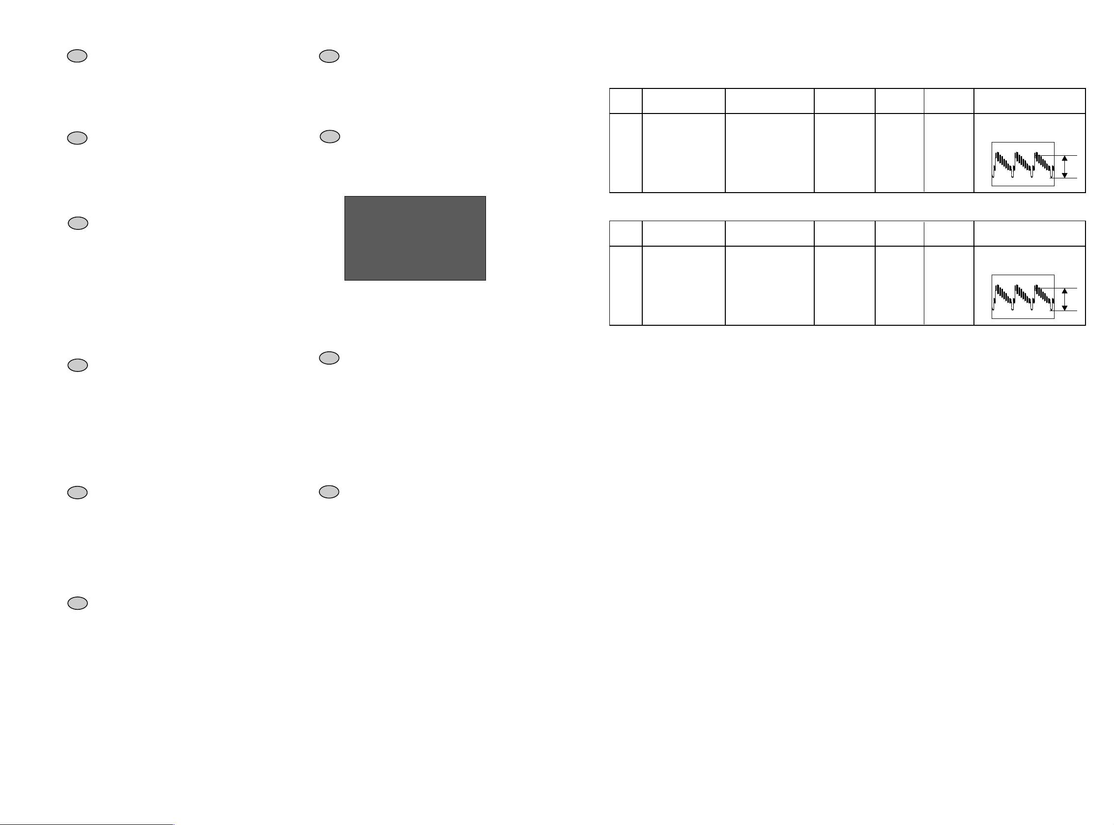
Item Mode & Signal Test equipment Test point Description
A CVBS PB level Oscilloscope AV1 pin19 None Check for CVBS= 1Vpp ± 0.1Vpp
Select AV1
PAL / SECAM
Adjustment
point
BW125
Video Playback Output Signal check - (Disk ) Controle Video Lecture Video - Überprüfung Videowiedergabepegel - Controllo uscita Riproduzione Video
Nivel de salida de reproduccion de video
BURST = 286mVpp ± 28,6 mVpp
( DVD )
( DVD disk test )
colour bar test pattern
20 BW125 (Top SCART)
colour bar test pattern
1Vpp
N
•
Item Mode & Signal Test equipment Test point Description
B CVBS EE level Oscilloscope AV1 pin19 None Check for CVBS= 1Vpp ± 0.1Vpp
Select AV1
PAL / SECAM
Adjustment
point
BW125
Video -E to E (AV input/AV output) - Video EE ( AV . Entree / Sortie AV ) - Video EE (AV-Eingang/AV-Ausgang) - Video -EE ( AV input/AV output - Video
EE (entrada / salida AV )
Page 8
DTH8040
First issue 12 / 04
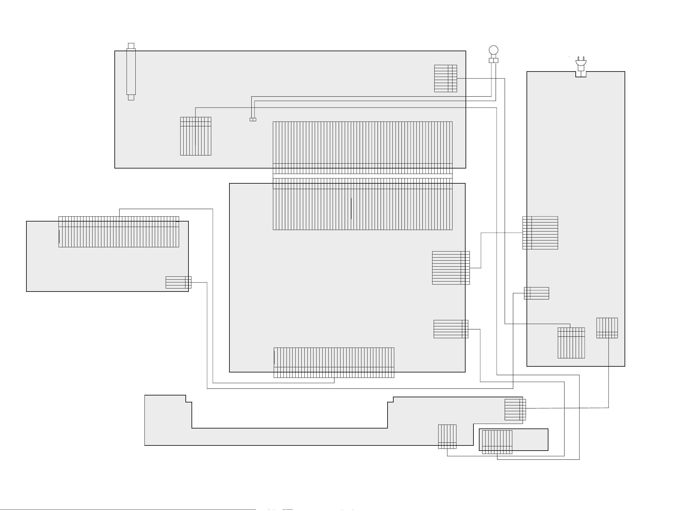
WIRING DIAGRAM - SCHEMA D’INTERCONNEXIONS - VERDRAHTUNGSPLAN - DIAGRAMMA DELLE INTERCONNESSIONI - ESQUEMA DE INTERCONEXIONES
FAN
21
TUNER
AV/TUNER(EU) BOARD
BB601A
+12VE
+40VS
GND
+9VE
+5VS
GND
+12VS
+5VE
9
8
7
6
5
3
24-5VE
1
AC
INLET
246
3
1
DGND
IDE_D7
IDE_RST
BB801H
8
10
9
7
5
1114151617181920212223
IDE_D3
IDE_D4
IDE_D5
IDE_D6
IDE_D9
IDE_D8
IDE_D11
IDE_D10
IDE_CONNECTOR
RICOH RW5240V24T
12
13
IDE_D2
IDE_D12
IDE_D1
IDE_D13
FEM
IDE_D0
IDE_D14
DGND
IDE_D15
NC
DGND
DMARQ
DIOW
24
DGND
25
DIOR
26
DGND
27282930313233343536373839
CS0
CS1
DA1
DA0
DA2
DGND
IORDY
DGND
DMACK
IDE_IRQ
HDD_NODD
PDIAG
BB301H
+12VS
GND
GND
+5VS_HDD
DASP
10
GND
40
DGND
975
864
C_FRONT_REC
Y_FRONT_REC
SV_F
GND
BB309A
1
2
3
4
R_FRONT
GND
3
2
L_FRONT
GND
1
CV_FRONT_REC
1
BW101
2
BB101A
POWER
DGND
DGND
IR_SAT
SPDIF_OUT
R_PR2H_DXX
SCART2_PIN8
246
5
3
1
DGND
IR_SAT
AV2_PIN8
SPDIF_OUT
R_PR2H_DXX
MODU_MODE_CTL
AGND
AVLINK_W
7
AGND
AGND
G_Y2H_DXX
AUDIO_SEL2
AUDIO_SEL1
B_PB2H_DXX
RGB_YUV_SEL
987654321
8
10
12
9
13
1114151617181920212223
AGND
AGND
G_Y2H_DXX
AUDIO_SEL1
AUDIO_SEL2
B_PB2H_DXX
RGB_YUV_SEL
CVBS_DXX
AGND
C_DXX
CVBS_DXX
181716151413121110
1920212223
AGND
Y_DXX
1H2H_SEL
AUD_R_OUT
HW_SW
AUD_R_OUT
AUD_L_OUT
24
24
DGND
AUD_L_OUT
AGND
AGND
AGND
Y_DXX
C_DXX
HW_SW
1H2H_SEL
DIGITAL BOARD
NC
GND
GND
AGND
AUD_R_REC
252627
26
25
DGND
AUD_R_REC
GND
AUD_L_REC
NICAM_RST
CV_TUNER1_REC
30
28
29
313233
272829303132333435363738394041424344454647484950515253545556575859
GND
GND
GND
CVBS1_REC
AUD_L_REC
NICAM_RST
EU_TUNER1_REC
NC
GND
GND
GND
S_CLK1
AVLINK_R
AV3/AV4_CV/Y_REC
34
35373941434547
GND
Y1_REC
AV3/AV4_C_REC
SCART_TV_CV/Y_REC
42
40
38
36
GND
DGND
S_IN1 S_IN1
S_CLK1
C1_REC
TUNER_REC
CVBS2_REC/G
SCART_VCR_CV/Y_REC
44
GND
Y2_REC/B
GND
FAN_FAIL
12C_CLK1
12C_DATA1
AUDIO_SEL3
SCART_VCR_C/R_REC
50
48
46
49
GND
FAN_ON
FAN_FAIL
C2_REC/R
12C_CLK1
12C_DATA1
GND
SCART2_B
SCART2_G
SCART2_FB
54
52
53
51
PR_REC
VDEC_VS
VDEC_HS
GND/SCART_FB
BB101D
SV_F
SV_R
DGND
16/9_S1
58
575655
DGND
16/9_S1
SV_R/SAPR-VS
SV_F/SAPR_HS
BB401D
+3V3SD
+2V5SD
+12VS_FLASH
PWR_DOWN
-5VE
16/9_S2
60
59
60
-5VE
16/9_S2
DGND
DGND
+9VE
+5VSA
AGND
+5VED
DGND
+3V3SD
1
GND
2
3
+2.5VS
4
GND
+12VS
5
6
+9VS
+5VSA
7
GND
8
9
PWR_OK
10
+5.4VE
GND
1
2
3
4
5
6
7
8
9
10
11
11
+12VS
1
GND
2
GND
3
+5VS_FEM
4
BOARD
BB401P
BB301P
DVDR SCH IDR04
WIRING DIAGRAM DTH8040E
DGND
IDE_RST
IDE_D7
IDE_D4
IDE_D5
IDE_D9
IDE_D6
IDE_D8
IDE_D10
987654321
KDB BOARD
IDE_CONNECTOR
IDE_D1
IDE_D2
IDE_D3
IDE_D14
IDE_D13
IDE_D12
IDE_D11
10
NC
DIOR
DIOW
IDE_D0
DGND
IDE_D15
DMARQ
2120191817161514131211
DGND
DGND
DGND
DGND
IORDY
DMACK
22232425262728293031323334353637383940
DGND
IDE_IRQ
HDD_NODD
DA17
PDIAG
BB801D
CS1
CS0
DA2
DA0
DASP
DGND
BB206D
VFD_DATA
VFD_STB
VFD_CLK
DGND
BB206K
I2C_CLK
KDB_RST
I2C_DATA
3
1
2
NC
IR
DGND
VFD_IQR
AV2_PIN8
654
BB201P
1
2
3
4
5
6
1
-VKK
PWR_OK
2
VFD_ON
3
-FL
BB201K
C_FRONT
GND
10
9
S_2
8
Y_FRONT
AGND
6
7
R_FRONT
AGND
4
5
L_FRONT
3
+FL
DGND
+5VE
CV_FRONT
GND
2
1
4
5
6
7
FAV BD
BB309F
BB601P
9
+13.5VE
+40VS
2345678
+12VS_FAN
+5.4VE1
+5VSA
+9VS
-5VE
GND
GND
-FL
+FL
-VKK
VFD_ON
PWR_OK
1234567
DGND
+5.4VE
Page 9
DTH8040
First issue 12 / 04
Mainsvoltage
POWE
Part of board connected to mains supply.
Partie du châssis reliée au secteur.
Primärseite des Netzteils.
Parte dello châssis collegata alla rete.
Parte del chassis conectar a la red.
Use isolating mains transformer.
Utiliser un transformateur isolateur du secteur.
Einen Trenntrafo verwenden.
Utilizar un transformador aislador de red.
Utilizzare un transformatore per isolarvi dalla rete.
Achtung :
Bei Messungen im Primärnetzteil
- Primärnetzteilmasse verwenden ( ).
Note :
Power Supply primary circuit measurements.
- Use only ( ) connection point.
Attention :
Mesure dans la partie primaire de l'alimentation
- Utiliser la masse du bloc alimentation ( ).
Attenzione :
misure nell'alimentatore primario
- usare massa alimentazione primario ( ).
Cuidado :
Medida en el bloque de alimentacion
- Utilizar la masa del bloque de alimentacion ( ).
Safety Part
When repairing, use original part only
Pièce de securité
N'utilisez que les pièces d'origine
Utilice solo piezas originales
Bei Ersatz nur Originalteil verwenden
Sicherheitsbauteil
Pieza de seguridad
Per la riparazione utilizzare solo componenti originali
Componenti di sicurezza
220R
RP058
22uF/50V
CP069
10R
RP056
4x1N4007
DP003
DP002
DP005
DP004
1000uF/16V
CP058
*
FP001
STP22NF03L
TP052
*
RP019
RP022
180K/0.25W
100nF
CP002
TL431
IP052
RGP10G
DP013
47uF/50V
CP062
2200uF/6.3V
CP053
6u8H
LP055
470uF/10V
CP061
S410D
DP065
STPS2045CT/MBR2045CT/MBRP2045N
DP052
A2A1
C
4K53/1%
RP080
7K5/1%
RP070
ECK
A
TCET1103G
IP050
1
2
3
4
10K
RP052
*
RP044
10K
RP048
1000uF/16V
CP063
S410D
DP059
JP100
IN4148
DP088
BZX55C6V8
DP069
*
RP054
10k
RP053
BC858B
TP058
*
RP041
20K
RP050
7R5/0.25W
RP078
KTC3112B
TP066
1N4148
DP055
1uF/50V
CP066
3K6/1W
RP083
IN5817
DP063
47uF/50V
CP086
BP001
1
2
6K8
RP059
2K2/1W
RP062
RP011
*
*
CP010
*
RP015
2n2F/400V
CP050
RN2402
TP065
*
RP014
23mH
LP002
1
2
4
3
*
RP013
IN4148
DP070
*
CP014
*
RP012
CP008
*
*
RP018
BZX55B33
DP009
IN4148
DP057
BC848B
TP054
2200uF/6.3V
CP054
390R
RP071
KTC3112B
TP011
1K
RP072
470uF/10V
CP074
47uF/50V
CP057
RP010
470R
BZX55C15
DP012
BZX55C15
DP011
1K24
RP060
BC848B
TP053
1K05
RP061
RGP15G
DP010
*
RP024
10R
RP023
*
CP016
6V2/1.3W
DP056
BB301P
1
2
3
4
*
RP043
*
RP042
*
TP041
*
RP051
*
RP082
BB701P
1
2
3
4
*
TP076
*
RP046
*
DP068
10K/0.25W
RP097
*
TP055
1N4148
DP086
TP010
HEATSINK
STP6NK90ZFP
BC848B
TP059
*
TP077
10K
RP047
9V1
DP089
2n2F
CP071
KTC8050D
TP088
470uF/10V
CP055
6V2/1.3W
DP090
2n2F
CP073
1R5/7W
RP055
RGP10G
DP008
STP22NF03L
TP061
2K
RP092
*
RP085
2K2/1W
RP079
4K7
RP073
10uF
CP065
*
RP081
*
RP069
470R
RP084
2n2F
CP078
2137005C
SCH_SMPS_IDR04_360MM
2n2F
CP079
LP050
1
2
3
4
5
6
7
8
9
10
11
12
13
14
1516
17
120R
RP094
*
TP044
0R
LP010
12
RGP10G
DP066
*
RP095
2n2F
CP080
2n2F
CP081
2n2F
CP087
2n2F
CP085
*
TP078
2n2F
CP082
*
CP013
2n2F
CP084
(PREP)
TP070
100nF
CP068
P
T1.25A_125V
FP051
470uF/10V
CP064
*
RP096
10K
RP074
(PREP)
RP089
(PREP)
RP090
(PREP)
RP091
(PREP)
TP073
100R
RP088
BC848B
TP067
P
T1.25A_125V
FP050
120R
RP093
(PREP)
CP088
*
RP087
BC848B
TP064
10K
RP067
(PREP)
CP017
*
RP021
10K
RP066
*
RP045
2n2F
CP077
*
CP015
*
RP020
(PREP)
CP095
120R
RP101
*
RP077
10uF/50V
CP076
1R
RP100
*
RP098
*
TP056
0R
RP099
BB601P
1
2
3
4
5
6
7
8
9
(PREP)
CP099
(PREP)
CP098
(PREP)
CP096
(PREP)
CP097
BB201P
1
2
3
4
5
6
7
4p7F
CP094
4p7F
CP093
BB401P
1
2
3
4
5
6
7
8
9
10
11
*
CP018
470uF/10V
CP060
(PREP)
CP092
470pF/1KV
CP091
470pF/1KV
CP090
750R/2W
RP063
(PREP)
TP086
330R
RP065
*
RP049
-FL
-FL
VDRIVE
VDRIVE
PWR_OK
PWR_OK
PWR_OK
PWR_OK
VKK
VKK
GND
GND
GND
GND
GND
GND
GNDGND
GND
GND
GNDGND
GND
GND
GND
GND
GND
GND
GND
GND
GND
GND
GND
GND
GND
GND
GND
GND
GND
GNDGND
GND
GND
GND
GND
GND
GND
GND
GND
GND
GND
GND
GND
GND
GND
GND
GND
GND
GND
GND
GND
PGNDPGND
PGND
PGND
PGND
PGND
PGND
PGNDPGND
PGND
PGND
PGND
PWR_ON/OFF
PWR_ON/OFF
VDRIVE_1
VDRIVE_1
+5VS_FEM
+13.5VE
+5.4VE
VFD_ON
VFD_ON
+FL
+FL
+40VS
100R/1W-RP098
-0RRP077
330R1KRP013
200R/2W470R/2WRP024
1nF/1KV
4n7F/63V33nF/63VCP014
27K47KRP012
-
-
18K
180K
180K
180K
180K
18K
150uF/400V
13-05-0
B
BD434TP056
100R/1WRP098
KTC8050DTP076
100pF/1KV470pF/2KVCP010
RP046
-0RRP096
0RRP095
RN2402
TP077
TP078
RN2402
3K6/1W-
-
-
-
-
RP082
-0RRP081
8n2F/63VCP016
10uF/50V-CP018
-100nFCP015
KTA1273Y
100K
1K
620R
2n2FCP013
-0RRP087
100R/1W
1N4148DP068
TP055
9K1RP049
RP014
47K
"-" MEANS NO PART INSERTED
NOTE:
T_1.0AL_250VT_1.6AL_250V
FP001
10M8M2RP015
EU(VAL)US(VAL)EU(VAL)US(VAL)
0RRP085
BC858BTP044
BC858BTP041 -
-
-
-
-
-
-
12K100KRP069
68K100KRP054
9K110KRP051
-RP045
-RP044
22K-RP043
-RP042
1K0RRP041
RP021
RP020
RP019
R390/2W R68/2.5WRP011
220uF/200VCP008
91K
91K
91K
91K
RP018
* REF. DES. * REF. DES.
(PREP)
/1%
/1%
PGND
PGND
PGND
PGND
PGND
SCH_SMPS_IDR04_360MM
2
2
0,1
0,3
-18,5
-18,5
-17,7
5,2 5,3 5,4
0,1
-1
-1
4,8
5,3
5,4
5,4
6
5,4
13,5
13,5
9,3
9,9
13,7
12,3
0
4,3
4,8
5,2
2,5
4,6
4,6
3,9
39
38,8
19,3
0,2
5
0,7
3,4
3,3
2,8
5,4
5,7
5,3
5,2
5,5
0
+40VE
+40VE
+3.3VS
+3.3VS
+5VS_FEM
+12VS
+12VS
+12VS
+13.5VE
+2.5VS
+2.5VS
+5.4VE
+5.4VE
+5.4VE
+5.4VE
+5.4VE
+5.4VE
+5.4VE
+5.4VE
+5.4VE
+5.4VE
+9VS
+9VS
+9VS
+12VS_FAN
+12VS_FAN
-5VE
-5VE
+5VSA
+5VSA
+5VSA
+5VSA
+5VSA
+40VS
+300
+40VS
+40VS
Somes Models
300 : On, EE Voltage
T=4,6us
T=4,6us
700Vpp
0
0
10Vpp
(+303)
(0)
(0,5)
(1,6)
(2,5)
(2)
(4)
(0)
(-15,6)
(5,2)
(12,8)
(5,4)
(5,4)
(5,4)
(3,3)
(2,6)
(0,2)
(0,7)
(0,2)
(0,7)
(0,7)
(5,4)
(5)
(5,4)
(5,4)
(9,3)
(0)
(0,1)
(0)
(5,3)
(5,4)
(0,1)
(--16,3)
(--16,4)
(0,8)
(-0,8)
(-0,9)
(0,1)
(5,5)
(5)
(0)
(0)
(5,5)
(5)
(35,1)
(303) : Standby, EE Voltage
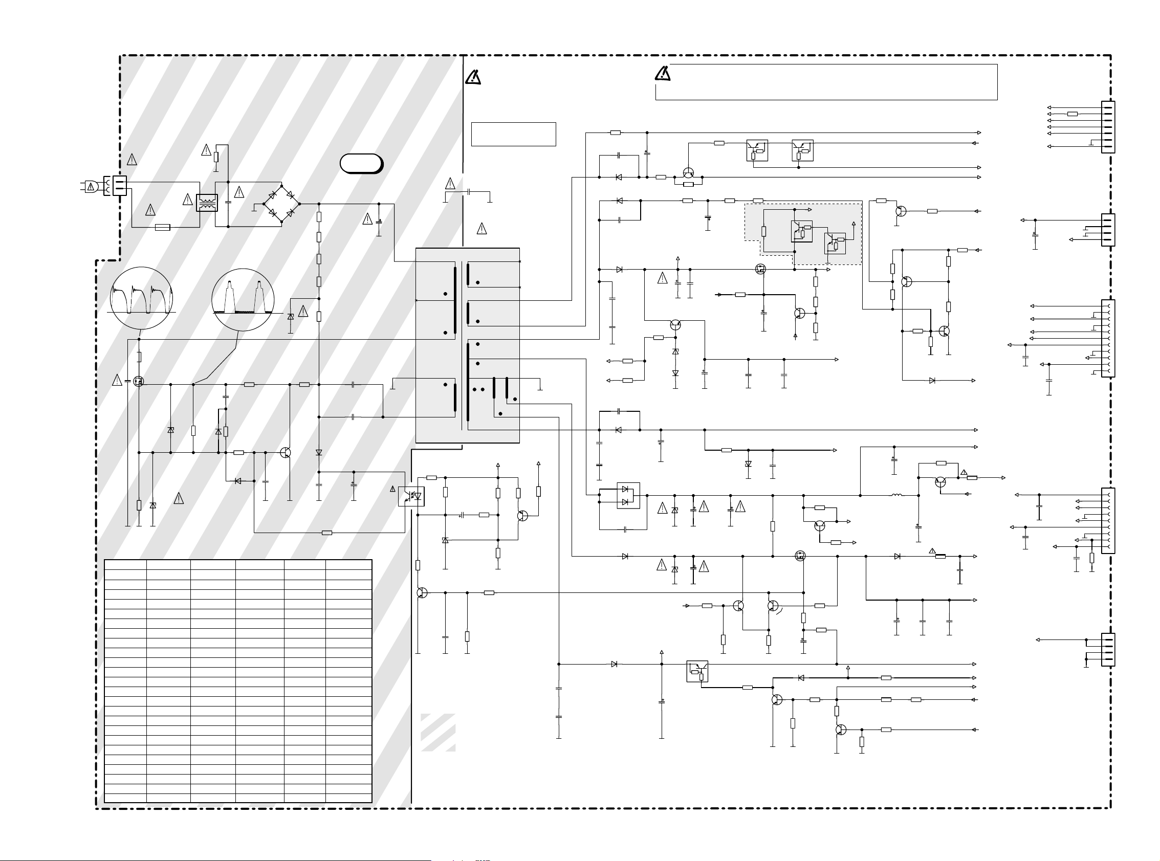
POWER SUPPLY INTERFACE - INTERFACE ALIMENTATION - NETZTEIL - ALIMENTAZIONE - INTERFAZ ALIMENTACIÓN
SCHEMATIC DIAGRAM - SCHEMA DE PRINCIPE - SCHALTBILD - SCHEMA - ESQUEMA
Page 10
DTH8040
First issue 12 / 04
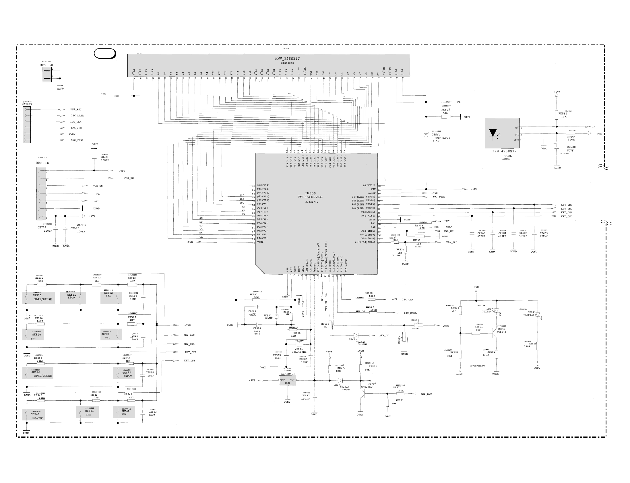
KEYBOARD WITH DISPLAY - PLATINE DE COMMANDES AVEC AFFICHEUR - BEDIENTEIL MIT DISPLAY - TASTIERA CON DISPLAY - PLATINA MANDOS CON VISUALIZADOR
SCHEMATIC DIAGRAM - SCHEMA DE PRINCIPE - SCHALTBILD - SCHEMA - ESQUEMA
KDBSCH IDR04 KDB LP03
Page 11
DTH8040
First issue 12 / 04
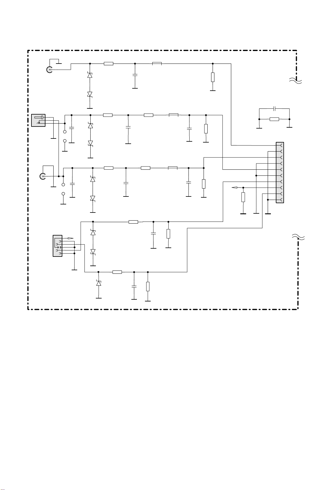
SOCKETS SCHEMATIC DIAGRAM - SCHEMA PRISES SCHALTUNG ANSCHLUSSPLATTE
SCHEMA PRESE - ESQUEMA TOMAS
RE808
DE801
6V8
DE810
6V8
DE802
6V8
DE803
6V8
DE804
6V8
DE805
6V8
0R
RE807
330R
RE833
330R
CE802
47PF
AGND
AGND
GND
CE806
1NF
RE810
18R
CE805
1NF
RE801
330R
RE800
330R
LE800
18R
LE801
F.BEAD
680R
LE802
F.BEAD
680R
CE801
330PF
(PREP)
CE800
330PF
(PREP)
AGND
AGND
AGND
AGND
GND
RE811
470K
RE812
470K
RE802
56R
S_2
RE817
270PF
GND
AGND
AGND
GND
CE815
12PF
RE815
0R
BB309F
1
2
3
4
5
6
7
8
9
10
GND
CV_FRONT
GND
L_FRONT
AGND
R_FRONT
AGND
Y_FRONT
S_2
C_FRONT
GND
BE803
AUDIO_R
BE802
AUDIO_L
1
GND
2
BE801
VIDEO
AGND
1
3
2
12
CE833
330PF
(PREP)
SG01
AGND
1
2
AGND
AGND
12
SG02
AGND
AGND
AGND
CE832
330PF
(PREP)
AGND
AGND
YKF51-5558
BE804
S_VIDEO
DE806
DE807
6V8
AGND
GND
6V8
DE809
6V8
RE809
18R
CE803
47PF
6
S_2
2
4
5
3
1
GND
GND
CE804
47PF
GND
GND
RE803
56R
GND
RE804
56R
FRONT_AV_LP03 21376190
SCH_IDR04_FAV_LP03
00_LR10.0.04
Page 12

DTH8040
First issue 12 / 04
( AV TUNER BOARD 1/6 )
SCART INTERFACE / TUNER SCHEMATIC DIAGRAM SCHEMA DE L’INTERFACE PERITELEVISION / TUNER - SCHALTBILD EUROPA NORMBUCHSE / TUNER
SCHEMA DELLA PRESA PERITEL / SINTONIZZATORE - ESQUEMA INTERFAZ EUROTOMA / SINTONIZADOR
BB101A
SKC
1
2
3
4
5
6
7
8
9
10
11
12
13
14
15
16
17
18
19
20
21
22
23
24
25
26
27
28
29
30
31
32
33
34
35
36
37
38
39
40
41
42
43
44
45
46
47
48
49
50
51
52
53
54
55
56
57
58
59
60
DGND
AGND_OUT
GND
GND
DGND
SCART2_PIN8
IR_SAT
15K
RW104
SPDIF_OUT
R/PR2H_DXX
AVLINK_W
G/Y2H_DXX
B/PB2H_DXX
GND
AUDIO_SEL1
AUDIO_SEL2
RGB_YUV_SEL
CVBS_DXX
C_DXX
Y_DXX
1H/2H_SEL
HW_SW
AUD_R_OUT
AUD_L_OUT
AUDIO_R_REC
NICAM_RST
AUDIO_L_REC
CV_TUNER1_REC
AV3/AV4_CV/Y_REC
SCART_TV_CV/Y_REC
S_IN1
S_CLK1
AV3/AV4_C_REC
AVLINK_R
SCART_VCR_CV/Y_REC
SCART_VCR_C/R_REC
AUDIO_SEL3
FAN_FAIL
I2C_DATA1
I2C_CLK1
SCART2_G
SCART2_FB
SCART2_B
SV_F
SV_R
16/9_S1
16/9_S2
-5VE
SCART_VCR_C/R_REC
SCART_VCR_CV/Y_REC
RW105
10K
AUDIO_SEL1
AUDIO_SEL2
AUDIO_SEL3
TUNER1_L_1
TUNER1_R_1
TUNER1_L
SCART_TV_L
SCART_TV_R
SCART_VCR_L
SCART_VCR_R
Y_OUTPUT
C_OUTPUT
SCART_VCR_G
SCART_VCR_B
S_CLK1
CVBS_DXX
R/PR2H_DXX
G/Y2H_DXX
B/PB2H_DXX
AUD_L_OUT
AUD_R_OUT
R/PR2H_DXX
B/PB2H_DXX
RGB_YUV_SEL
AUD_L_OUT
AUD_R_OUT
I2C_CLK1
I2C_DATA1
SPDIF_OUT
TUNER1_R
S_IN1
Y_DXX
C_DXX
G/Y2H_DXX
1H/2H_SEL
HW_SW
16/9_S1
16/9_S2
CVBS_DXX
Y_DXX
C_DXX
AUDIO_SEL1
AUDIO_SEL2
AUDIO_SEL3
TUNER1_L_1
TUNER1_R_1
TUNER1_L
TUNER1_R
SCART_TV_L
SCART_TV_R
SCART_VCR_L
SCART_VCR_R
Y_OUTPUT
C_OUTPUT
+33VS
SCART_VCR_G
SCART_VCR_B
S_IN1
S_CLK1
CVBS_DXX
Y_DXX
C_DXX
R/PR2H_DXX
G/Y2H_DXX
B/PB2H_DXX
AUD_L_OUT
AUD_R_OUT
SCART_VCR_C/R_REC
SCART_VCR_CV/Y_REC
R/PR2H_DXX
G/Y2H_DXX
B/PB2H_DXX
1H/2H_SEL
RGB_YUV_SEL
HW_SW
16/9_S1
16/9_S2
CVBS_DXX
Y_DXX
C_DXX
AUD_L_OUT
AUD_R_OUT
+5VE
+5VS
sheet 2
I2C_CLK1
I2C_DATA1
SPDIF_OUT
TUNER
DGND
DGND
+5VE+5VS
+5VE+5VS -5VE
Sheet 3
A/V SWITCHIN G
INPUTS
AGND_OUT
AGND_OUT
-5VE
+12VS
A/V SWITCHIN G
+5VE
SCARTS
sheet 4
+5VS
+5VS
Sheet 5
A/V OUTPUTS
AGND_OUT
AGND_OUT
+33VS+9VE +12VS
+12VS +33VS+5VE +5VS+9VE
FAN_FAIL
NICAM_RST
S_CLK1
S_IN1
TUNER1_L
TUNER1_R
CV_TUNER1_REC
CVBS_VPS/PDC
-5VE
SV_R
SV_F
AUDIO_R_REC
AUDIO_L_REC
AV3/AV4_CV/Y_REC
AV3/AV4_C_REC
+5VS
+5VS+5VE-5VE+12VS+33VS
+12VE
+9VE
+12VE+9VE
CVBS_VPS/PDC
TUNER1_L_1
TUNER1_R_1
SCART_TV_CV/Y_REC
SCART_TV_CV/Y
SCART_TV_L
SCART_TV_R
SCART2_FB
SCART2_R
SCART2_G
SCART2_B
SCART_VCR_CV/Y
SCART_VCR_C/R
SCART_VCR_L
SCART_VCR_R
AV_PIN10
SCART2_PIN8
C_OUTPUT
Y_OUTPUT
AV TUNER IDR04 EU
DTH8040E AV/TUNER
FAN_FAIL
NICAM_RST
S_CLK1
S_IN1
TUNER1_L
TUNER1_R
CV_TUNER1_REC
CVBS_VPS/PDC
SV_R
SV_F
AUDIO_R_REC
AUDIO_L_REC
AV3/AV4_CV/Y_REC
AV3/AV4_C_REC
CVBS_VPS/PDC
TUNER1_L_1
TUNER1_R_1
SCART_TV_CV/Y_REC
SCART_TV_CV/Y
SCART_TV_L
SCART_TV_R
SCART2_FB
SCART2_R
SCART2_G
SCART2_B
SCART_VCR_CV/Y
SCART_VCR_C/R
SCART_VCR_L
SCART_VCR_R
AV_PIN10
SCART2_PIN8
C_OUTPUT
Y_OUTPUT
AV_PIN10
+5VS
0A-SO
2138236B
+5VS
DGND
+5VS
DGND
CVBS_VPS/PDC
Sheet 6
VPS/PDC CIRCUIT
+5VE
4K7
+5VE
10K
RW133
TW127
BC847B
SPDIF_OUT
IR_SAT
RW130
GND
RW131
RW137
LA504
22U
12K
DW126
1N4148W
100R
CW106
100N0
RW112
5K6
14-06-04
RW132
LA503
1K/100MHZ
CW107
100P
120K
DGND
DGND
S_CLK1
GND
CA502
100N
S_IN1
DGND
RW134
RW138
33K
DGND
RW113
150R
8K2
GND
RW139
33K
DGND
BA501
1
INPUT
2
VCC
3
GND
LW114
4U7
TW102
BC847B
2
1
DGND
BC858B
TW126
RW136
10K
CA503
100P
BW100
CVBS_VPS/PDC
S_CLK1
S_IN1
RW135
39K
OPTICAL
COAXIAL
B
A
AVLINK_R
AVLINK_W
DIGITAL
OUTPUT
+5VS
Page 13

DTH8040
First issue 12 / 04
( AV TUNER BOARD 2/6 )
SCART INTERFACE / TUNER SCHEMATIC DIAGRAM - SCHEMA DE L’INTERFACE PERITELEVISION / TUNER - SCHALTBILD EUROPA NORMBUCHSE / TUNER
SCHEMA DELLA PRESA PERITEL / SINTONIZZATORE - ESQUEMA INTERFAZ EUROTOMA / SINTONIZADOR
ZI601
FE6235
(FM_SW)
AGC
SCL
SDA
+5V_T1
+5V_T2
NC1
NC2
NC3
AUDIO
SIF/AS
GND
VIDEO
FM_IF
+5V_IF
NC4
NC5
LUG1
LUG2
SKCTUNER
TUNER_MONO_AUDIO
+5VE
CI500
1
2
PS
3
AS
4
5
6
7
8
9
VT
10
11
12
13
14
15
16
17
18
19
20
21
22
RI601
GND
100P0
GND
10K0
CI601
47P
GND
GND
CI604
100N0
GND
CI549
47N0
GND
TUNER_MONO_AUDIO
GND
RI610
82R
1
GND
CI608
100N0
GND
100N0
GND
RI602
150R
RI603
150R
CI602
47P
CI603
100P0
GND GND
GND
GND
CI605
100P0
TUNER_SIF
RI611
270R
CI607
47P
CI609
100P0
+5VS_TUNER
GND GND
CI508
22U0
CI511
22U0
GND
CI606
47P
CI501
100P0
LI505
10U0
CI502
GND
+5VS_TUNER
RI604
FBEAD
RI605
FBEAD
GND
LI504
4.7U
RI612
620R
+5VS
+33VS
LI501
4.7U
CVBS_VPS/PDC
CV_TUNER1_REC
I2C_CLK1
I2C_DATA1
+5VS
AGND
LA100
4.7U
TUNER_SIF
AGND
AGND
CA101
470P0
CA104
I2C @
S_CLK1
S_IN1
TUNER
DTH8040E AV/TUNER
AGND
5P0
CA105
5P0
W:0x88 R:0x89
AGND
CA122
CA103
56P0
QA100
18M432
1U0
RA100
100R0
CA100
10U0
AGND
CA102
56P0
RA108
0
10
11
RA101
100R0
AGND
1
AVSUP
2
ANA_IN1+
3
ANA_IN-
4
TESTEN
5
XTAL_IN
6
XTAL_OUT
7
TP
8
D_CTR_OUT1
9
D_CTR_OUT0
ADR_SEL
STANDBYQ
AGND
CA123
470P0
2
1
CW108
100U
16V
44
12
MGND
BW101
43
AVSS
I2C_CL
13
CW102
100U
MGNDMGND
42
VREFTOP
I2C_DA MONO_IN
TP
14
CA106
470P0
LW101
10U0
RW108
180R
CA120
100N0
CA121
10U0
39
40
41
NC
SC1_IN_L
SC1_IN_R
IA100
MSP3417D
TP
TPTPTP
151617
CA107
10U0
AGND
RW101
10K
RW103
4K7
AGND
AGND
AGND
38
NC
TP
18
AGND
+12VS
37
NC
DVSUP
19
AGND
MGND
AGND
36
AGNDC
DVSS
20
RA102
10K0
+5VS
MGND
RW114
10K
CA117
100N0
CA116
10U0
35
AHVSS
21
22
AGND
RW102
1K
TW103
BC847B
34
CAPL_M
RESETQ
CA108
100N0
+5VS
MGND
AGND
AGND
AHVSUP
SC1_OUT_L
SC1_OUT_R
VREF1
DACM_L
DACM_R
VREF2
RA103
100R0
BC857B
TW104
RW106
4K7
CA115
1U0
NC
TP
TP
TP
1N4148W
DW101
33
32
31
30
29
28
27
26
25
24
23
+5VS
MGND
DA100
1N4148W
CA114
100N0
AGNDAGND
RA104
1K0
RA105
1K0
AGND
AGND
TV SOUND DEMODULATOR DECODER
0
Reset
1
No Reset
NICAM_RST
RW107
1N4148W
1K
DW102
TW105
RN1402N
MGND
CA113
10U0
RW109
4K7
LA101
10U0
CA109
3N3
CA110
3N3
FAN_FAIL
+9VE
AGND
AGND
RX863
RX865
GND
Power FROM Upper Level
Signal FROM Upper Level
Signal TO Upper Level
CV_TUNER1_REC
TUNER1_L
TUNER1_R
CVBS_VPS/PDC
FAN_FAIL
TUNER1_L
TUNER1_R
RX891
0
RX892
0
DGND
0
0
AGND
+33VS
+5VS
+5VE
+9VE
+12VS
DGND
S_CLK1
S_IN1
I2C_CLK1
I2C_DATA1
SPDIF_OUT
NICAM_RST
MGND
RX862
0
RX864
0
DGND
LUG3
LUG4
23
24
Address Btye
For Tuner
For IF
Hex Code
C2
86
Page 14

DTH8040
First issue 12 / 04
( AV TUNER BOARD 3/6)
SCART INTERFACE / TUNER SCHEMATIC DIAGRAM - SCHEMA DE L’INTERFACE PERITELEVISION / TUNER - SCHALTBILD EUROPA NORMBUCHSE / TUNER
SCHEMA DELLA PRESA PERITEL / SINTONIZZATORE - ESQUEMA INTERFAZ EUROTOMA / SINTONIZADOR
A/V Switching Inputs
BB309A
1
2
3
4
5
6
7
8
9
10
GND
CX021
CX020
47P0
47P0
GND
BW520
MTJ-035-33R-BBA-432
YELLOW
WHITE
RED
S-VIDEO IN
BW541
YKF51-5571
S-VIDEO OUT
GND
5
4
3
2
1
GND
SKC
CX022
47P0
10
9
8
7
11
4
3
2
1
5
6
12
GND
CX023
47P0
GND
GND
GND
AGND_OUT
GND
GND
CW544
PREP
CW541
PREP
CX024
47P0
DW548
BZT55C6V8
RW543
470R
RW540
470R
TUNER1_R
TUNER1_L
+5VS
GND
GND
RW550
6K2
RW551
18K
GND
GND
GND
CW543
470P0
CW540
470P0
SV_R
C_OUTPUT
Y_OUTPUT
GND
RX026
18K
CW545
47P0
(prep)
RX025
6K2
RW547
22R
RW545
470R
RW542
470R
10U
CW582
10U
CW583
RX871
0R0
L_FRONT
R_FRONT
Y_FRONT_REC
SV_F
C_FRONT_REC
GND
CW549
47P0
RW546
56R
GND
GND
GND
CW547
47P0
CX013
100P0
GND
+5VE
CV_REAR_REC
RW544
100K0
RW541
100K0
GND
RW515
33K0
GND
CV_FRONT_REC
-5VE
RW553
22R
DW554
BZT55C6V8
RW548
22R
RW549
56R
GND
GND
LW570
L_REAR
R_REAR
RW516
33K0
GND
GND
4U7
CW571
100U0
RW552
56R
GND
CV_REAR_REC
Y_REAR_REC
-5VE_VIDEO
GND
DW551
BZT55C6V8
L_REAR
AV3/AV4_L
L_FRONT
CW572
100N0
C_REAR_REC
Y_REAR_REC
GND
2
3
4
5
6
7
8
GND
SCART_TV_R
SCART_TV_L
SCART_VCR_R
SCART_VCR_L
AV3/AV4_L
AV3/AV4_R
Y0
Z1
Z
Z0
E
VEE
GND
HEF4053
PART_TYPE=10292210
Audio_sel2
L
L
H
H
IW510
TUNER1_L_1
AUD_L_REC1
-5VE
GND
L
H
L
H
TUNER1_R_1
1
2
3
4
5
6
7
8
Output signalAudio_sel1
AV1
AV2
Tuner_Audio
AV3/AV4
VCCY1
Y
X
X1
X0
A
B
C
-5VE_VIDEO
2Y2
2Z
2Y3
2Y1
E
VEE
GND
161
15
AV4_CV/Y
14
AV3_CV/Y
13
CV_FRONT_REC
12
Y_FRONT_REC
11
SV_F
10
SV_R
9
AUDIO_SEL3
C_REAR_REC
C_FRONT_REC
AV3/AV4_R
CW573
100N0
GND
IW501
744052
R_REAR
R_FRONT
A/V Switching Inputs
DTH8040E AV/TUNER
22-06-04
2138236B
GND
0A-SO
+5VE_VIDEO
CW427
100N0
GND
VCC2Y0
1Y2
1Y1
1Y0
1Y3
2
Y0
3
Z1
4
Z
5
Z0
6
E
7
VEE
8
GND
16
15
14
13
1Z
12
11
10
S0
9
S1
AUD_L_REC1
AUD_R_REC1
LW360
4U7
21369280
CW426
100U0
GND
IW520
HEF4053
PART_TYPE=10292210
+5VE
GND
RW579
1K
RW578
1K
+5VE
CW504
100N0
AUD_R_REC1
RW517
10K0
GND
GND
CW579
100P0
(prep)
CW578
100P0
(prep)
Power FROM Upper Level
+5VE
+5VS
-5VE
+5VE_VIDEO
CW428
161
VCCY1
15
Y
14
X
13
X1
12
X0
11
A
10
B
9
C
+5VE
RW518
10K0
CW580
10U
CW581
10U
100N0
GND
AV3/AV4_C_REC
AV3/AV4_CV/Y_REC
AV4_CV/Y
AV3_CV/Y
10K0
RW372
AUDIO_SEL3
AUDIO_SEL2
AUDIO_SEL1
AUDIO_L_REC
AUDIO_R_REC
+5VE
AGND_OUT
Signal FROM Upper Level
AUDIO_SEL1
AUDIO_SEL2
AUDIO_SEL3
TUNER1_L
TUNER1_R
SCART_TV_R
SCART_TV_L
SCART_VCR_R
SCART_VCR_L
C_OUTPUT
Y_OUTPUT
Signal TO Upper Level
AUDIO_R_REC
AUDIO_L_REC
AV3/AV4_CV/Y_REC
AV3/AV4_C_REC
SV_F
SV_R
Page 15

DTH8040
First issue 12 / 04
( AV TUNER BOARD 4/6)
SCART INTERFACE / TUNER SCHEMATIC DIAGRAM - SCHEMA DE L’INTERFACE PERITELEVISION / TUNER - SCHALTBILD EUROPA NORMBUCHSE / TUNER
SCHEMA DELLA PRESA PERITEL / SINTONIZZATORE - ESQUEMA INTERFAZ EUROTOMA / SINTONIZADOR
A/V SWITCHING SCARTS
SKC
BB601A
+12VE
+40VS
+12VS
SCART_VCR_B
SCART_VCR_CV/Y
9
8
7
GND
6
+9VE
5
+5VS
4
GND
3
2
-5VE
1
+5VE
SCART_VCR_G
+5VE
CW123
100N0
CVBS_VPS/PDC
CVBS_DXX
TUNER1_R_1
TUNER1_L_1
R/PR2H_DXX
AUD_R_OUT
G/Y2H_DXX
AUD_L_OUT
B/PB2H_DXX
SCART_TV_CV/Y
SCART_VCR_L
SCART_VCR_R
SCART_TV_L
SCART_TV_R
GND
+12VE
GND
Y_DXX
C_DXX
GND
GND
LW124
4U7
CW125
100U0
GND
GND
GND
CX855
100P
CX861
100P
LW010
39N
LW011
39N
GND
GND
CW147
100P
CW191
47P0
+12VE
GND
RW182
0R0
RW183
0R0
LW121
4U7
CW126
100N0
CW127
CW128
CW129
CW130
CW131
CW132
CW133
CW134
CW135
CW136
CW137
CW138
GND
+5VS
GND
CX863
100P
+5VE_F
GND
1U0
100N0
1U0
1U0
1U0
1U0
1U0
1U0
1U0
1U0
1U0
1U0
CW148
100P
CW192
47P0
GND
CX854
100P
+5VE
1N4148W
DW130
+9VE
RX860
100R0
0.25W
SCART2_G
SCART2_B
CW122
100U0
SCART_VCR_B
CW139
220N0
GND
CW141
CW143
CW145
GND
DX860
5V1
1U
1U0
1U0
GND
GND
GND
CX853
100P
1
2
3
4
5
6
7
8
9
10
11
12
13
14
15
16
CW140
100U0
+33VS
RX852
1K2
2.0W
CX860
10U
GND
CW159
100N0
GND
CW160
220N0
VCC
CVBSIN_AUX
DEC
Y/CVBSIN_ENC
GND1
YIN_ENC
RIN_AUX
C_ENC
LIN_AUX
R/CIN_ENC
RIN_ENC
GIN_ENC
LIN_ENC
BIN_ENC
NC1
VREF
CW142
1U0
CW144
1U
CW146
A/V SWITCHING SCARTS
DTH8040E A/V TUNER
DX852
BZX55B33
+12VS
GND
-5VE
CX851
100P
GND
220N0
CW158
CW157
220N0
64
SDA
G_VCR
R/C_VCR
SLB_VCR
LIN_VCR
RIN_VCR
CVBSIN_TV
GND3
IT_OUT
SLB_TV
IW151
STV6412AD
LIN_TV
RIN_TV
VCCA
GNDA
GND
VCC12
B_VCR
GND2
Y/CVBSIN_VCR
171819202122232425262728293031
GND
1U0
CX852
100U0
GND
RW120
0
RW121
0
GND
SCL
VDD
ADD
C_GATE
NC2
ROUT_CINCH
LOUT_CINCH
ROUT_VCR
SCART_VCR_C/R
SCART_VCR_C/R_REC
LW123
10U0
CW156
100N0
495051525354555657585960616263
FBIN_ENC
FBIN_VCR
FBOUT_TV
Y/CVBSOUT_VCR
COUT_VCR
Y/CVBSOUT_TV
R/COUT_TV
GOUT_TV
BOUT_TV
VOUT_RF
AOUT_RF
LOUT_TV
LOUT_VCR
VCCAO
ROUT_TV
32
CW151
47N0
GND
CW150
22U0
SCART_VCR_G
SLB_VCR
SCART_VCR_C/R
SLB_TV
S_IN1
S_CLK1
+5VE_F
GND
48
47
VCCB1
46
45
VCCB2
44
43
VCCB3
42
41
GNDB
40
39
VCCB4
38
37
VCCB5
36
35
34
FILTER
33
RW124
22R
GND
CW149
22U0
Y/CV_VCR
GND
CW153
22U0
CW124
100N0
RW370
56R
GND
BZT55C6V8
GND
CW155
100N0
22U0
CW152
GND
SCART_VCR_B
SCART_VCR_G
RW146
22R
DW812
CW113
5N6
FB_VCR
FSTV_OUT
Y/CV_VCR
+5VE_F
Y/CV_TV
C/R_TV
G_TV
B_TV
LOUT_TV
LW137
10U0
CW185
100U0
LOUT_VCR
ROUT_VCR
GND
SLB_VCR
BZT55C6V8
GND
G_TV
GND
ROUT_TV
DW815
RW152
75R0
RW151
1K0
1(L)
0(H)
DEFAULT
CW154
100N0
+9VE
AV_PIN10
GND
RW140
470R0
CW163
1N0
SCART2_PIN8
GND
DW816
BZT55C6V8
GND
RW304
CW172
47P0
GND
GND
ROUT_TV
SCART_TV_R
LOUT_TV
SCART_TV_L
C/R_VCRC-gate TW125
OFF OUT
ON MUTE
ON MUTE
DW806
BZT55C6V8
GND
SCART_TV_CV/Y_REC
GND
DW803
BZT55C6V8
0
CW114
5N6
SLB_TV
RW156
1K0
C/R_TV
FSTV_OUT
Y/CV_TV
SCART_TV_CV/Y
RW369
56R
ROUT_VCR
SCART_VCR_R
LOUT_VCR
SCART_VCR_L
GND
FB_VCR
SCART2_FB
SCART_VCR_CV/Y
SCART_VCR_CV/Y_REC
CW095
100P0
B_TV
RW157
75R0
CW175
47P0
GND
RW169
22R
GND
75R0
RW147
RW149
470R0
RW371
RW164
470R0
GND
BZT55C6V8
56R
GND
GND
RW148
CW096
100P0
BZT55C6V8
DW813
GND
75R0
GND GNDGND GND
DW819
BZT55C6V8
RW153
22R
DW814
BZT55C6V8
RW199
470K0
BZT55C6V8
DW820
DW808
BZT55C6V8
GND
GN
CW094
100P0
CW168
DW805
GND
47P0
GND
GND
GND
CW092
100P0
RW189
RW194
330R0
GND
GND
GND
DW807
BZT55C6V8
RW165
GND
RW300
CW169
75R0
RW150
GND
GND
1K0
RW521
CW184
47P0
470K0
RW301
RW302
47P0
47P0
CW097
100P0
CW181
GND
0
RW303
CW171
GNDGND
RW305
0
CW173
RW154
1K0
1N0
RW192
47P0
CW170
GND
RW158
RW166
GND
RW190
470K0
330R0
GND
GND
0
0
47P0
GND
1K0
75R
RW167
CW193
47P0
0
CW194
47P0
GND
RW155
1K0
CW093
0
RW195
RW196
RW197
RW198
75R0
CW174
47P0
GND
GND
100P0
CW098
100P0
RW310
RW159
75R0
GND
0
GNDGND
CW182
47P0
RW168
75R0
GND
RW193
330R0
RW188
470K0
RW309
GND
RW191
330R0
RW110
330R0
330R0
330R0
330R0
0
CW176
47P0
RW519
GND
CW091
100P0
330R0
0
RW311
0
0
RW520
CW183
47P0
GN
RW144
330R0
GND
GND
0
GND
330R0
RW143
RW142
CW115
330R0
RW162
330R0
RW163
RW141
10N
330R0
RW161
GND
CW167
CW166
CW165
CW164
330R0
BOTTOM SCART
GND
330R0
RW160
(
22)
23)
(
24)
(
25)
(
26)
(
27)
(
28)
(
29)
(
30)
(
(
31)
(
32)
(
33)
(
34)
(
35)
(
36)
(
37)
(
38)
39)
(
(
40)
(
41)
(
42)
1N0
1N0
1N0
1N0
VCR SCART
BW125
1
2
3
4
5
6
7
8
9
10
11
12
13
14
15
16
17
18
19
20
21
GND
CW180
CW179
CW178
CW177
TV SCART
TOP SCART
BW125
1
2
3
4
5
6
7
8
9
10
11
12
13
14
15
16
17
18
19
20
21
1N0
1N0
1N0
1N0
GND
GND GND GND
Power FROM Upper Level
+5VS
+12VE
+5VE
+9VE
+12VS
-5VE
+33VS
Signals FROM Upper Level
B/PB2H_DXX
G/Y2H_DXX
R/PR2H_DXX
TUNER1_L_1
TUNER1_R_1
CVBS_VPS/PDC
CVBS_DXX
Y_DXX
C_DXX
S_IN1
S_CLK1
AUD_R_OUT
AUD_L_OUT
GNDGNDGND GND
Signals TO Upper Level
AV_PIN10
SCART2_PIN8
SCART_VCR_C/R
SCART_VCR_R
SCART_VCR_L
SCART_VCR_CV/Y
SCART_TV_R
SCART_TV_L
SCART_TV_CV/Y
SCART_VCR_B
SCART_VCR_G
SCART2_B
SCART2_G
SCART2_R
SCART2_FB
Page 16

DTH8040
First issue 12 / 04
( AV TUNER BOARD 5/6
SCART INTERFACE / TUNER SCHEMATIC DIAGRAM - SCHEMA DE L’INTERFACE PERITELEVISION / TUNER - SCHALTBILD EUROPA NORMBUCHSE / TUNER
SCHEMA DELLA PRESA PERITEL / SINTONIZZATORE - ESQUEMA INTERFAZ EUROTOMA / SINTONIZADOR
A/V Outputs
SKC
Signal to upper level
Power to upper level
GND
RGB_YUV_SEL
RW631
18K
+5VS
HW_SW
R/PR2H_DXX
G/Y2H_DXX
B/PB2H_DXX
CVBS_DXX
Y_DXX
C_DXX
AUD_L_OUT
AUD_R_OUT
AGND_OUT
HW_SW
RGB_YUV_SEL
1H/2H_SEL
C_OUTPUT
Y_OUTPUT
16/9_S1
16/9_S2
+5VS
RW618
10K
+5VS_OUT
RW632
2K7
RW633
GND
BC857B
TW610
RW619
2K7
AGND_OUT
18K
C_DXX
CVBS_DXX
Y_DXX
1
2
3
4
GND
G/Y2H_DXX
B/PB2H_DXX
R/PR2H_DXX
+5VS
SW612
65
A: 1-2
B: --3
C: 2-4
AGND_OUT
LW601
4U7
CW601
100N
CW602
100N
CW605
100N
CW604
22U
CW245
100N
CW255
100N
CW265
100N
+5VS_OUT
CW603
100U0
AGND_OUT
Switch Position
RGB_OUTPUT 1H_OUTPUT 2H_OUTPUT
RGB_SEL
HW_SW
HX X
L
DTH8040E AV/TUNER
A/V Outputs
IW600
MM1623
VCC1 VCC2
2
C_IN
3
MUTE1
4
CVBS_IN
5
YC_MIX
6
Y_IN
7
GND1
8
BIAS
9
I/P
10
CY_IN
11
12
CB_IN
13
MUTE2
14 15
CR_IN
RW271
0
1
1H
2H
0
CBA
HL
Y_O1
1H/2H_SEL
S-DC_OUT
C_OUT
S1
S2
CVBS_OUT
GND2
Y_OUT
CY_OUT
GND2
CB_OUTCLP
GND2
CR_OUT
GND2
281
27
26
25
24
23
22
21
20
19
18
17
16
+5VS_OUT
AGND_OUT
CW644
AGND_OUT
CW600
100N0
RW645
4K7
100N0
16/9_S1
16/9_S2
CW681
470U
CW682
470U
CW680
470U
AUD_L_OUT
AUD_R_OUT
RW635
75R0
1N4148W
DW621
AGND_OUT
RW670
75R0
RW660
75R0
RW650
75R0
DW622
1N4148W
RW646
75R0
DW623
DW624
AGND_OUT
AGND_OUT
AGND_OUT
AGND_OUT
AGND_OUT
AGND_OUT
AGND_OUT
1N4148W
AGND_OUT
1N4148W
CW645
47P
(prep)
CW635
47P
(prep)
CW671
VAL?
(prep)
CW661
VAL?
(prep)
CW651
VAL?
(prep)
CW626
PREP
CW627
PREP
RW625
75R0
RW616
56R0
RW611
56R0
DW640
BZT55C6V8
AGND_OUT
DW630
BZT55C6V8
AGND_OUT
Y_1H2H
BZT55C6V8
AGND_OUT
PB_1H2H
AGND_OUT
PR_1H2H
AGND_OUT
AGND_OUT
AGND_OUT
AGND_OUT
DW670
DW660
BZT55C6V8
DW650
BZT55C6V8
CW625
47P
AGND_OUT
CW615
1N
CW610
1N
YPbPr Out
MTJ-035-33R-BBB-752
DW620
BZT55C6V8
C_OUTPUT
S-VIDEO OUT
Y_OUTPUT
BW612
4
3
2
1
AGND_OUT
RW615
56R0
RW610
56R0
GREEN
BLUE
RED
AGND_OUT
REAR OUTPUT 1
BW610
MTJ-035-33R-BBA-432
5
YELLOW
4
WHITE
3
RED
2
1
Page 17

DTH8040
First issue 12 / 04
( AV TUNER BOARD 6/6 )
SCART INTERFACE / TUNER SCHEMATIC DIAGRAM - SCHEMA DE L’INTERFACE PERITELEVISION / TUNER - SCHALTBILD EUROPA NORMBUCHSE / TUNER
SCHEMA DELLA PRESA PERITEL / SINTONIZZATORE - ESQUEMA INTERFAZ EUROTOMA / SINTONIZADOR
VPS/PDC CIRCUIT
SKC
IE900
ADM207EAR
DGND
DGND
DGND
1
VSS1
2
X_TA_1IN
3
X_TA_1OUT
4
CRTL1
5
NC
6
SDA
7
SCL
8
SYN_CJDG
9
HOUT
10
VSS2
11
CPOUT
12 13
VCOIN VCOR
CRTL2
SEPIN
SEPOUT
SYNIN
VDD1
RST
CDLR
VOUT
SEPC
VDD2
DAV
24
23
22
21
20
19
18
17
16
15
14
CE900
1U0
RE903
10K
RE905
5K6
+5VS_VPS/PDC
RE902
0R
CE904
1U0
RE900
10K
CE903
DGND
56NF
RE920
0R
RE904
10K
DGND
DGND
+5VS
DGND
+5VS_VPS/PDC
CE901
100N0
+5VS_VPS/PDC
LE900
4U7
CE922
CE921
100N0
DGND DGND DGND
100U0
RX901
0
CE923
100N0
DGND
CE906
DGND
DGND
S_IN1
S_CLK1
1U
DGND
RE906
2K7
CE905
CE908
12P
QE900
CE907
12P
RE908 0
RE909 0
RE907
10K
56NF
CVBS_VPS/PDC
DGND
CE924
CE925
1U0
1U0
6
IN1
4
IN2
DGND
BIAS
CLAMP CLAMP
IE901
MM1508
13
SW
VCC
DRV.
GND
5
DGND
62MI5
RX902
0
CE902
100N0
DGND
2
OUT
GND
62MI5
RX903
0
62MI5
DGND
DTH8040E_A
VPS/PDC CIRCUIT
Page 18

DTH8040
First issue 12 / 04
(DIGITAL BOARD 1/9)
MAIN SCHEMATIC DIAGRAM - SCHEMA DE LA PLATINE PRINCIPALE - SCHALTBILD HAUPTPLATINE - SCHEMA DELLA PIASTRA PRINCIPALE- ESQUEMA DE LA PLATINA PRINCIPAL
BLOCK DIAGRAMS
MPEG
NICAM_RST
TO/FROM
SV_F/SAPR_HS
SHT8
SV_R/SAPR_VS
PWR_FAIL
FROM SHT6
+3V3SD +5VED
+3V3SD +5VED
NICAM_RST
SV_F/SAPR_HS
SV_R/SAPR_VS
PWR_FAIL
GOBSTOPPER
SHT4of9
VDEC_RST
VDEC_HS
VDEC_FLD
CLA_ACLK
CLAHI_CWE
CLAHI_CRE
CLAHI_CCS
CLAHI_INT
CLAU_RST
PSTOP
OSVLD
OSREQ
OS[0:7]
OSCLK/OSSTB
OSSYNC
ATAPI_IORDY
IDE_RST
IDE_IRQ
ATAPI_DIOW
ATAPI_DIOR
ODD_ATAPI_RST
ADMCLK
FPA_IRQ
KDB_RST
PCMCLK
EMI_AD[1:21]
EMI_D[0:15]
DXX_RST
GS_IRQ0
GS_IRQ1
DXXHSYNC
DXX_FLD
GS_IRQ2
SYS_RST
DXX656_BUF
RNOTW
MEMWAIT
PPC_CLK
BUF_OE
NSTATUS
NCONFIG
INIT_DONE
GOB_RST
DGND
DGND
FROM
SHT8
CE1
CE2
WE0
WE1
OE
Y2_REC/B
Y1_REC
C2_REC/R
TUNER_REC
C1_REC
EU_CVBS_REC
VDEC_RST
VDEC_HS
VDEC_FLD
CLA_ACLK
CLAHI_CWE
CLAHI_CRE
CLAHI_CCS
CLAHI_INT
CLAU_RST
PSTOP
OSVLD
OSREQ
OS[0:7]
OSCLK/OSSTB
OSSYNC
ATAPI_IORDY
IDE_RST
IDE_IRQ
FPA_IRQ
KDB_RST
PCMCLK
EMI_AD[1:21]
EMI_D[0:15]
DXX_RST
GS_IRQ0
GS_IRQ1
DXXHSYNC
DXX_FLD
GS_IRQ2
SYS_RST
DXX656_BUF
RNOTW
MEMWAIT
PPC_CLK
BUF_OE
NSTATUS
NCONFIG
INIT_DONE
GOB_RST
ATAPI_DIOW
ATAPI_DIOR
ODD_ATAPI_RST
ADMCLK
CE1
CE2
OE
WE0
WE1
TO SHT3
FROM SHT10
TO/FROM SHT6
TO/FR.SHT8
Y2_REC/B
Y1_REC
C2_REC/R
TUNER_REC
EU_CVBS_REC
VDEC_RST
VDEC_HS
FROM SHT2,6
PCMLRCLK
PCMSCLK
PCMDATA0
PCMDATA3
DAC_MUTE
27CK_DXX
S_CLK
IR_DXX
PWR_DOWN
IR_SAT
SPDIF_OUT
FAN_FAIL
FAN_ON
AV2_PIN8
RGB_YUV_SEL
C1_REC
VDEC_FLD
FROM SHT6
S_IN
IR
+3V3SD
+3V3SD
VIDEO_DECODER
SHT2of9
ENGR: KELVIN
GND
GND
I2C_CLK
I2C_DATA
16/9_S1
16/9_S2
CLA_VID[0:7]
CLA_VCLKI
ADMCLK
VDEC_HS
VDEC_VS
DGND
DGND
+5VED +1V8SD
FPA_IRQ
KDB_RST
PCMCLK
EMI_AD[1:21]
EMI_D[0:15]
DXX_RST
GS_IRQ0
GS_IRQ1
DXXHSYNC
DXX_FLD
GS_IRQ2
CE1
CE2
OE
SYS_RST
WE0
WE1
DXX656_BUF
PCMLRCLK
PCMSCLK
PCMDATA0
PCMDATA3
DAC_MUTE
27CK_DXX
RNOTW
MEMWAIT
PPC_CLK
S_CLK
S_IN
IR
IR_DXX
PWR_DOWN
BUF_OE
NSTATUS
NCONFIG
INIT_DONE
GOB_RST
IR_SAT
SPDIF_OUT
FAN_FAIL
FAN_ON
AV2_PIN8
RGB_YUV_SEL
MPEG
DECODER
SHT7of9
ENGR: CHEN YC
AGND
AGND
VDEC_HS
VDEC_VS
+1V8SD +3V3SD+5VED
DGND
DGND
FROM/TO
SHT3
I2C_CLK
I2C_DATA
16/9_S1
16/9_S2
CLA_VID[0:7]
CLA_VCLKI
ADMCLK
TO SHT8
+3V3SD
FROM SHT7
TO SHT8
TO SHT4
ADSCLK
ADLRCLK
ADSDATA1
DXX_DIOW
DXX_DIOR
IR_DXX
RNOTW
R_OUT
C_OUT
Y_OUT
G_OUT
B_OUT
CV_OUT
MODU_MODE_CTL
I2C_DATA1
I2C_CLK1
AUDIO_SEL1
HW_SW
AUDIO_SEL2
1H2H_SEL
S_IN1
S_CLK1
CLA_VCLKI
CLA_VID[0:7]
I2C_CLK
I2C_DATA
E2PROM_EN
SYS_CS
PPC_CLK
MEMWAIT
FLASH_WR
CAS0
RAS0
AV_CS0
AV_RAS
AV_CAS
AV_WE
AV_QDML
AV_QDMU
AV_SDCLK
AV_MA[0:13]
AV_MD[0:15]
+3V3SD
+2V5SD
+2V5SD+3V3SD
WE0
WE1
RNOTW
EMI_AD[1:21]
EMI_D[0:15]
Shielding:
(1) Must be shielded by AGND: CV_OOU, Y_OUT, C_OUT, R_OUT, G_OUT, B_OUT, CVBS_DXX, Y_DXX, C_DXX, R_PR2H_DXX, G_Y2H_DXX, B_PB2H_
(2) Must be shielded by GND: Y1_REC, CVBS2_REC/G, C1_REC, TUNER_REC, CVBS1_REC, EU_CVBS_REC
(3) Must be shielded by DGND: 27CK_DXX, CLA_STCLK, 27CK_CLA, ADMCLK, PPC_CLK, S_CLK, S_CLK1, S_IN, S_IN1, I2C_CLK, I2C_CLK1, I2
-5VE
+5VSA
+5VSA
R_OUT
C_OUT
Y_OUT
G_OUT
B_OUT
CV_OUT
MODU_MODE_CTL
I2C_DATA1
I2C_CLK1
AUDIO_SEL1
HW_SW
AUDIO_SEL2
1H2H_SEL
S_IN1
S_CLK1
EU_CVBS_REC
Y1_REC
TUNER_REC
EMI_AD[1:21]
EMI_D[0:15]
WE0
WE1
OE
RNOTW
I2C_CLK
I2C_DATA
DXX_RST
Y2_REC/B
C1_REC
C2_REC/R
FROM/TO SHT7
FROM/TO SHT4
TO SHT2
OE
EU_CVBS_REC
Y1_REC
Y2_REC/B
TUNER_REC
C1_REC
C2_REC/R
CHEN YC
IDR04 2ND GEN DIGITAL
CIRCUIT DIAGRAM
BLOCK DIAGRAMS
DGND
DGND
DECODER
SHT8of9
AGND
AGND
MPEG
VOUT
CLA_VID[0:7]
CLA_VCLKI
ADSCLK
ADLRCLK
ADSDATA1
CLA_ACLK
CLAHI_CWE
CLAHI_CRE
CLAHI_CCS
CLAHI_INT
CLAU_RST
PSTOP
OSVLD
OSREQ
OS[0:7]
OSCLK/OSSTB
OSSYNC
DXX_DIOW
DXX_DIOR
CE1
IR
CE3
CE1
IR
IR_DXX
RNOTW
R_OUT
C_OUT
Y_OUT
G_OUT
B_OUT
CV_OUT
MODU_MODE_CTL
I2C_DATA1
I2C_CLK1
AUDIO_SEL1
HW_SW
AUDIO_SEL2
1H2H_SEL
S_IN1
S_CLK1
CLA_VCLKI
CLA_VID[0:7]
I2C_CLK
I2C_DATA
E2PROM_EN
SYS_CS
PPC_CLK
MEMWAIT
CE3
FLASH_WR
CASO
RASO
AV_CSO
AV_RAS
AV_CAS
AV_WE
AV_QDML
AV_QDMU
AV_SDCLK
AV_MA[0:13]
AV_MD[0:15]
ENCODER
SHT5of9
DGND
DGND
MPEG
SHT2,3,9
EMI_AD[1:21]
EMI_D[0:15]
CLA_STCLK
TO/FROM
TO
27CK_CLA
SHT5
E2PROM_EN
SYS_CS
PPC_CLK
MEMWAIT
CE3
FLASH_WR
CAS0
RAS0
AV_CS0
AV_RAS
AV_CAS
AV_WE
AV_QDML
AV_QDMU
ENGR: CHEN YC
AV_SDCLK
AV_MA[0:13]
AV_MD[0:15]
27CK_CLA
CLA_STCLK
+12VS_FLASH
+12VS_FLASH +3V3SD
EMI_AD[1:21]
EMI_D[0:15]
MEMORY
SHT9of9
DGND
DGND
+3V3SD
I2C_CLK
I2C_DATA
DXX_RST
-5VE
RGB_YUV_SEL
AV2_PIN8
SPDIF_OUT
FAN_FAIL
NICAM_RST
SV_F/SAPR_HS
SV_R/SAPR_VS
VDEC_HS
VDEC_VS
AUD_L_OUT
AUD_R_OUT
AUD_L_REC
AUD_R_REC
GND
GND
+2V5SD +1V8SD+5VED
+2V5SD +3V3SD+5VED +5VSA+9VE
EMI_AD[1:21]
EMI_D[0:15]
27CK_CLA
CLA_STCLK
ATAPI_IORDY
IDE_RST
IDE_IRQ
DXX_DIOW
DXX_DIOR
CE1
IR
IR_DXX
RNOTW
IR_SAT
FAN_ON
16/9_S1
16/9_S2
+9VE
CLOCK/ATAPI/PWR
AGND
AGND
FROM SHT7
SHT6of9
+3V3SD
DGND
DGND
RGB_YUV_SEL
AV2_PIN8
IR_SAT
SPDIF_OUT
FAN_FAIL
FAN_ON
NICAM_RST
SV_F/SAPR_HS
SV_R/SAPR_VS
16/9_S1
16/9_S2
VDEC_HS
VDEC_VS
AUD_L_OUT
AUD_R_OUT
AUD_L_REC
AUD_R_REC
I2C_CLK
I2C_DATA
+5VSA
+1V8SD
+12VS_FLASH
27CK_DXX
PWR_DOWN
PWR_FAIL
ATAPI_DIOR
ATAPI_DIOW
ODD_ATAPI_RST
FROM/TO SHT7
FROM SHT4
FROM SHT2
+3V3SD
+9VE +5VSA
+3V3SD +5VSA+9VE -5VE
AUD_L_OUT
AUD_R_OUT
AUD_L_REC
AUD_R_REC
I2C_CLK
I2C_DATA
AUDIO_CODEC
SHT3of9
ENGR: SUN GL
+12VS_FLASH
27CK_DXX
PWR_DOWN
PWR_FAIL
ATAPI_DIOR
ATAPI_DIOW
ODD_ATAPI_RST
-5VE
ADSCLK
ADLRCLK
ADSDATA1
PCMCLK
PCMLRCLK
PCMSCLK
PCMDATA0
PCMDATA3
DAC_MUTE
DGND
IDR04_2ND_GEN
TO SHT4 & SHT7
FROM
SHT7
TO SHT4
FROM /TO
DGND
SHT4
ADSCLK
ADLRCLK
ADSDATA1
PCMCLK
PCMLRCLK
PCMSCLK
PCMDATA0
PCMDATA3
DAC_MUTE
FROM/TO
SHT5
FROM
SHT7
Page 19

DTH8040
First issue 12 / 04
(DIGITAL BOARD 2/9)
MAIN SCHEMATIC DIAGRAM - SCHEMA DE LA PLATINE PRINCIPALE - SCHALTBILD HAUPTPLATINE - SCHEMA DELLA PIASTRA PRINCIPALE- ESQUEMA DE LA PLATINA PRINCIPAL
VIDEO DECODER
MPEG
Y2_REC/B
C2_REC/R
TUNER_REC
EU_CVBS_REC
+3V3SD
+3V3SD
Y1_REC
C1_REC
FV001
FV004
31R0
31R0
GND
CV004 100N
CV047
47U0
GND
(11)
(1)
DGND
CV042
100N
VDDD33
100NCV002
100NCV001
RV018
GND
CV031
(17) (23)
GND
(25) (51)
CV006
CV003 100N
CV007
PREP
GND
100P
CV043
100N
GND
100N
100N
RV007
CV044
100N
FV002
31R0
68R0
CV028
CV027
DGND
VDDA33
(75) (33)
VDDD33
RV008
8P2
8P2
I2C_DATA
I2C_CLK
DGND
CV012
10K
VDEC_RST
(43)
CV029
100N
RV005
XV001
32M11HZ
21312930
100N
CV011
TPV01
(58)
VDDD33
3343586893
VDDI2
VDDI1
SAA7115
NTSC/PAL
DECODER
VDDI3
21257870
VSSI1
38
VDDI4
IV001
VSSI2
83
VDDI5
VSSI3
88
755125
1
8
VXDD
VDDE1
VDDE2
VDDE3
VDDE4
20
AI11
18
AI12
16
AI21
14
AI22
12
AI23
10
AI24
19
100N
RV006
10K
10K
TPV02
RV015
0R
0R
RV016
(68) (83)
AI1D
13
AI2D
22
AOUT
99
TMS
2
TDO
3
TDI
98
TCK
97
TRST
6
XTALO
7
XTALI
4
XTOUT
32
SDA
31
SCL
30
RESON
27
CE
44
TEST0
73
TEST1
74
TEST2
77
TEST3
78
TEST4
79
TEST5
VXSS
5
DGND
(93)
VSSE1
506326
VSSE2
76
VSSE3
100
VSSE4
VDDD33
VDDI6
GND
21
AGND
VSSA0
24
VDDA33
VSSA1
15
23
VDDA0
VSSA2
9
17
VDDA1
11
VDDA2
IPD7
IPD6
IPD5
IPD4
IPD3
IPD2
IPD1
IPD0
XPD7
XPD6
XPD5
XPD4
XPD3
XPD2
XPD1
XPD0
HPD7
HPD6
HPD5
HPD4
HPD3
HPD2
HPD1
HPD0
XCLK
XDQ
XRH
XRV
XTRI
XRDY
ICLK
IGPH
IGPV
ITRI
ITRDY
IGP0
IGP1
LLC
LLC2
RTS0
RTS1
RTCO
AMCLK
ASCLK
ALRCLK
AMXCLK
DGND
54
55
56
57
59
60
61
62
81
82
84
85
86
87
89
90
64
65
66
67
69
70
71
72
94
95
92
91
80
96
45
46
IDQ
53
52
47
42
48
49
28
29
34
35
36
37
39
40
41
RV003
(PREP)
RV001
RV017
RV002
4K7
NV001 47R0
8
7
6
5
8
7
6
5
NV002
47R0
RV004
47R
PREP
IDR04 2ND GEN DIGITAL
CLA_VCLKI
VDEC_VS
16/9_S1
16/9_S2
VDEC_HS
VDEC_FLD
18P
CV030
ADMCLK
TPV03
VIDEO DECODER
47R0
1
2
3
4
1
2
3
4
DGND
CLA_VID7
CLA_VID6
CLA_VID5
CLA_VID4
CLA_VID3
CLA_VID2
CLA_VID1
CLA_VID0
DGND
CLA_VID[0:7]
RV014
PREP
RV013
4K7
16/9_S1
16/9_S2
TUNER_REC
EU_CVBS_REC
C2_REC/R
Y1_REC
Y2_REC/B
C1_REC
VDEC_RST
CLA_VID[0:7]
CLA_VCLKI
VDEC_HS
VDEC_FLD
ADMCLK
I2C_CLK
I2C_DATA
VDEC_VS
+3V3SD
DGND
GND
VDDD33
DGND
CV048
47U0
DGND
CV014
100N
DGND
CV015
100N
DGND
CV016
100N
CV017
CV018
100N
100N
DGNDDGND DGND DGND
CV019
100N
CV020
100N
DGND
CV021
100N
DGND
CV045
100N
DGND
CV046
100N
Page 20

DTH8040
First issue 12 / 04
(DIGITAL BOARD 3/9)
MAIN SCHEMATIC DIAGRAM - SCHEMA DE LA PLATINE PRINCIPALE - SCHALTBILD HAUPTPLATINE - SCHEMA DELLA PIASTRA PRINCIPALE- ESQUEMA DE LA PLATINA PRINCIPAL
AUDIO_CODEC
MPEG
AGND_AD
AGND_DA
AGND_D
AGND_HP
AUD_L_REC
AUD_R_REC
I2C_CLK
I2C_DATA
LCHLCH+
RCH-
RCH+
DIGITAL BD EU3
DIGITAL BD US3
JA002
JA003
#
PARTLIST
JA001
0R0
LA005
10U0
0R0
0R0
DGND
*
CA016
470P
DGND
#
#
RA023
100R0
RA024
100R0
RA021
6K8
RA022
6K8
CA017
470P
DGND
DGND
DGND
3V3D
CA014
CA018
470P
RA021/RA022
CA013
100N0
PREP
CA015
PREP
LA001
10U0
RA001
0R0
CA019
470P
6K8
6K8
CA001
100U0
2
4
10
16
17
18
21
20
22
30
32
31
34
33
36
35
+3V3SD
CA005
100U
VADCP
VSS_AD
LA003
10U0
RA003
AGND_AD
VADCN
0R0
VREF
VINL2
VINR2
TEST
SYSCLK
DATAAD1
DATAAD2
BCKAD
WSAD
WSDA
BCKDA
DATADA1
DATADA2
DATADA3
VOUT6N
VOUT6P
VOUT5N
VOUT5P
VOUT4N
VOUT4P
CA006
100N0
LA002
10U0
RA002
10R0
3V3DA
CA003
220U
CA004
CA002 RA004
100N0
AGND_D
VINL1
VINR1
VOICE
DATAV
BCKV
WSV
MCCLK
MCMODE
MCDATA
I2C_L3
VOUT1N
VOUT1P
VOUT2N
VOUT2P
VOUT3N
VOUT3P
100N0
AGND_DA
RA027
0R0
RA026
*
0R0
AGND_HP
53 9 71
VSS_DA
VDD_AD
VDD_DA
IA001
UDA1338H-SD
PARTS TO BE INSERTED IF UDA1384H 2-CH CODEC IS USED.
VDDD
*
37282940
VSSD
*
LA004
10U0
AGND_HP
CA007
100N0
6
8
11
19
RA005 100R
13
RA006
12
14
RA007
15
RA008 220R
23
RA009 0R0
24
RA010 0R0
25
RA011 0R0
26
RA012 PREP
27
RA014
RA015 0R0
44
RA016 0R0
43
DGND
42
41
39
RA020 0R0
38
CA023
100N0
220R0
CA008
47U0
AGND_AD
*
*
*
*
*
PREPCA021
3V3HP
3V3AD
100R
220R
0R0
AGND_DA
LCH-
LCH+
RCH-
RCH+
CA009
100N0
PCMCLK
ADSDATA1
ADSCLK
ADLRCLK
PCMLRCLK
PCMSCLK
PCMDATA0DAC_MUTE
PCMDATA3
DGND
3V3HP
3V3D
DAC_MUTE
DGND
RA100
4K75
RA101
4K75
4K75
RA201
4K75
DGND
RA103
RA200
RA203
CA010
47U0
5K6
5K6
CA109
3N3
DGND
CA209
3N3
DGND
+5VSA
RA300
CA300
10U0
RA301
22K
RA302
10K
DGND DGND DGND
RA102
5K6
RA104
180R
RA105
180R
RA202
5K6
RA204
180R
RA205
180R
AUDIO MUTE
22K
DGND
CA301
1U
DGND
DGND
CA105
330P
CA103
330P
CA205
330P
CA203
330P
2
3
-5VE
6
5
-5VE
DA300
1N4148W
RA304
RA303
4K7
TA300
BC847B
+9VSA
+9VSA
10K
IA100
8
1
MC33078
4
IA100
8
7
4
MC33078
CA210
100N0
RA305
330R0
IDR04 2ND GEN DIGITAL
RA206
100R0
CA211
10U0
DGND
TA301
BC857B
CIRCUIT DIAGRAM
AUDIO_CODEC
RA106
100R0
TA302
BC857B
AUDIO OP-AMP
RA107
56R0
CA107
100P0 1N0
DGND
RA207
56R0
CA207
100P0
DGND
+9VE
AMUTE
AMUTE
AMUTE
LA400
10U0
RA109
8K2
RA209
8K2
CA400
100N0
DGND
DGND
TA100
BC847B
TA200
BC847B
DGND
DGND
100U0
DGND
AUD_L_OUT
AUD_R_OUT
AUD_R_REC
AUD_L_REC
I2C_CLK
I2C_DATA
DGND
+3V3SD
+9VE
+5VSA
-5VE
ADSCLK
ADLRCLK
ADSDATA1
PCMCLK
PCMLRCLK
PCMSCLK
PCMDATA0
PCMDATA3
DAC_MUTE
CA108
CA401
RA108
CA208
1N0
56R0
RA208
56R0
+9VSA
AUD_L_OUT
AUD_R_OUT
DVDRW+VCR
10K
Page 21

DTH8040
First issue 12 / 04
(DIGITAL BOARD 4/9)
MAIN SCHEMATIC DIAGRAM - SCHEMA DE LA PLATINE PRINCIPALE - SCHALTBILD HAUPTPLATINE - SCHEMA DELLA PIASTRA PRINCIPALE- ESQUEMA DE LA PLATINA PRINCIPAL
GOBSTOPPER
MPEG
BOARD_RST
SYS_RST
+1V5
CG165
1U0
+3V3SD
CG119
10UF
DGND
+3V3SD
RG160
10K0
DGND
LD1117DT
CG124
100N0
RG153
30R1
DG101
1SS394
RG151
IG104
IN
20K0
RG201
PREP
RG202
PREP
ADJ
DGND
FG001
+3V3SD
RG149
24K3
CG115
100N0
DGND
310R
CG166
1U0 100N
DGND
OUT
RG152
150R
CG120
10UF
TPG07
TPG16
TPG17
TPG18
TPG21
TPG22
TPG23
TPG24
TPG25
TPG26
GS_IRQ0
DGND
1
2
3
4
CG167
CG121
10UF
TG101
BC847B
IG103
M51957B
DGND
DGND
DXX656_BUF
VDEC_HS
VDEC_FLD
VDEC_RST
ODD_RST
IDE_RST
SYS_RST
FPGA_RST
ODD_ATAPI_IRQ
ODD_ATAPI_RST
+3V3SD
DGND
CG168
10N
+3V3SD
NCONFIG
LOGGER_IRQ
LOGGER_CS
TPG05
CG125
100N0
RG176
10K
DGND
CG116
100NO
VCCA_PLL1
+1V5
RG177
8
7
6
5
GEM/ST9_RST
GEM_FS/VBI_BL
VBI_VC/PIP_BL
47K
CG117
100NO
+3V3SD
INIT_DONE
FS_BK
DXX656_BUF
DATA0
RG111
3K3
RG113
0R0
RG116
4K7
RG114
4K7
RG115
4K7
RG117
RG161
RG162
RG121
10K
DGND
PWR_FAIL
H_1H
VCCA_PLL1
4K7
4K7
4K7
CG118
100P0
PPC_CLK
CG129
10N0
(PREP)
4K7
RG163
DGND
RG150
2K2
RG156
PREP
RG157
0R0
DGND
RG110
3K3
RG197
RG180
V_1H
DGND
CLAHI_INT
CLAHI_CWE
4K7
RG122
CG173
RG106
CG174 1NO
RG107
RG108 1K0
CG175
RG109
CG176 1NO
0R0
GOB_RST
FPGA_RST
BOARD_RST
36R0
DCLK
ODD_ATAPI_IRQ
CE2
1K0
RG123
+3V3SD
FPGA_RST
DXX_RST
1NO
4K7
4K7
1NO
4K7
SV_F/SAPR_HS
SV_R/SAPR_VS
CG177
RG205
68R0
4K7
4K7
RG124
RG125
EMI_D0
CE2
BUF_OE
+3V3SD
CG169
22P0
DGND
1NO
RG196
RG198
RG199
RG126
RG164
RG175
0R0
RG200
0R0
4K7
10K
+3V3SD
RG112
+3V3SD
0R0
0R0
0R0
PREP
RG127
+1V5
CG126
VDEC_HS
0R0
RG120
RG119
0R0
(PREP)
137
138
GND
VCCI02
GND
VCCIO4
4K7
RG132
CG123
18P0
ODD_RST
136
GND
GND
RG133
135
4K7
100NO
(PREP)
EMI_AD20
EMI_AD21
EMI_AD19
132
133
134
IO
VCCINT
IO/DPCLK2
EP1C3T144
IOIOIO
IO/DPCLK7
VCCINT
33R0
RG134
DGND
IDE_IRQ
IDE_RST
CLA_ACLK
DGND
EMI_AD10
EMI_AD18
EMI_AD17
EMI_AD11
128
130
129
131
IG101
ATAPI_DIOR
ATAPI_DIOW
ATAPI_IORDY
RG170
0R0
RG169
0R0
RG168
10K
RG167
10K
EMI_AD7
EMI_AD8
EMI_AD9
125
126
127
IOIOIOIOIOIOIO
IOIOIO
PREP
RG130
RG204
PREP
CG128
68R0
DGND
+1V5
CLAU_RST
EMI_AD6
EMI_AD5
EMI_AD4
122
123
124
IO
IOIOIO
IOIOIOIOIO
IO
68R0
RG195
RG203
68R0
PSTOP
OSREQ
CLAHI_CRE
CLAHI_CCS
+3V3SD
DATA0
DCLK
EMI_AD3
EMI_AD2
EMI_AD1
119
120
121
IOIOIOIOIO
OSVLD
OSSYNC
+3V3SD
EMI_AD[1:21]
115
116
117
118
GND
GND
VCCINT
VCCIO2
IO/DPCLK3
GND
GND
VCCINT
PREP
RG136
4K7
RG135
OSCLK/OSSTB
EMI_D[0:15]
EMI_D13
EMI_D15
EMI_D14
112
113
114
IOIOIOIOIO
IO
VCCIO4
OS6
OS5
OS7
EMI_D11
EMI_D12
110
111
OS4
OS3
EMI_D10
109
IO
IOIOIOIOIO
7271706968676665646362616059585756555453525150494847464544434241403938
RG137
OS2
VCCIO3
DPCLK4/IO
NSTATUS
CONF_DONE
DPCLK5/IO
VCCI03
RG139
RG138
4K7
4K7
DGND
GND
CLK2
CLK3
TDO
TMS
TCK
GND
108
IO
107
IO
106
IO
105
IO
104
IO
103
IO
102
101
100
99
IO
98
IO
97
IO
96
IO
95
TDI
94
IO
93
92
91
IO
90
89
88
87
86
85
IO
84
IO
83
IO
82
81
80
79
IO
78
IO
77
IO
76
IO
75
IO
74
IO
73
IO
4K7
RG154
PREP
RG194
0R0
DGND
IDR04 2ND GEN DIGITAL
GOBSTOPPER
EMI_D9
EMI_D8
EMI_D7
EMI_D6
EMI_D5
EMI_D4
EMI_D3
EMI_D2
EMI_D1
EMI_D0
RG140
4K7
RG141
4K7
MEMWAIT
RNOTW
WE1
GS_IRQ1
GS_IRQ2
OE
DXXHSYNC
DXX_FLD
OS0
OS1
P64 P46
CG105 CG104
100NO
P102
CG113
100NO
CG127
CG178
CG179
CE1
+1V5
ADMCLK
PCMCLK
WE0
+3V3SD
CG103 CG102
100NO 100NO
P81
CG111
CG112
100NO100NO
PREP
PREP
PREP
DGND
RG155
PREP
RG142
10K
RG143
PREP
CG170
PREP
DGND
OS[0:7]
P15 P135
100NO
P66
CG110
DGND
P44
P117
CG101
100NO
P29
CG109
100NO
RG144
3K3
RG145
3K3
RG146
10K
RG147
10K
NSTATUS
CONF_DONE
+1V5
P137 P115
P8
CG106
CG107CG108
100NO
100NO
100NO100NO
+3V3SD
TPG27
TPG31
TPG28
TPG29
TPG30
+3V3SD
DGND
DGND
+3V3SD
OS[0:7]
OSCLK/OSSTB
OSSYNC
OSVLD
OSREQ
PSTOP
CLAHI_CRE
CLAHI_CCS
CLAHI_CWE
CLAHI_INT
CLAU_RST
ATAPI_DIOW
ATAPI_DIOR
ATAPI_IORDY
IDE_RST
IDE_IRQ
CLA_ACLK
SV_R/SAPR_VS
SV_F/SAPR_HS
PPC_CLK
DXX_RST
EMI_D[0:15]
EMI_AD[1:21]
CE1
CE2
MEMWAIT
RNOTW
WE0
WE1
GS_IRQ0
GS_IRQ1
GS_IRQ2
OE
DXXHSYNC
DXX_FLD
ADMCLK
PCMCLK
VDEC_HS
VDEC_FLD
VDEC_RST
NICAM_RST
FPA_IRQ
ODD_ATAPI_RST
NSTATUS
NCONFIG
INIT_DONE
BUF_OE
GOB_RST
KDB_RST
PWR_FAIL
SYS_RST
+5VED
DXX656_BUF
NICAM_RST
FPA_IRQ
KDB_RST
VDEC_RST
VDEC_FLD
RG101
PREP
RG102
4K7
RG103
4K7
RG104
4K7
DGND
139
140
141
142
143
144
IO
IOIOIOIOIO
1
IO/INIT_DONE
2
IO
3
IO/CLKUSR
4
IO
5
IO
6
IO
7
IO
8
VCCIO1
9
GND
10
IO/DPCLK1
11
IO
12
IO/NCSO
13
DATA0
14
NCONFIG
15
VCCA_PLL1
16
CLK0
17
CLK1
18
GNDA_PLL1
19
GNDG_PLL1
20
NCEO
21
NCE
22
MSEL0
23
MSEL1
24
DCLK
25
IO/ASDO
26
IO
27
IO
28
IO/DPCLK0
29
VCCIO1
30
GND
31
IO
32
IO
33
IO
34
IO
35
IO
36
IO
IOIOIO
IOIOIO
37
4K7
4K7
RG128
CG172
100PF
4K7
RG129
CG171
100PF
DGND
IG105
74LVTH244A
2
1A1
4
1A2
6
1A3
8
1A4
11
2A1
13
2A2
15
2A3
17
2A4
1
1OE
19
2OE
10
GND
DGND
4K7
RG131
VCC
1Y1
1Y2
1Y3
1Y4
2Y1
2Y2
2Y3
2Y4
USB_CS
USB_IRQ
ODD_IRQ
USB_RST
ODD_ATAPI_RST
20
CG164
100N0
DGND
18
16
14
12
9
7
5
3
Page 22

DTH8040
First issue 12 / 04
(DIGITAL BOARD 5/9)
MAIN SCHEMATIC DIAGRAM - SCHEMA DE LA PLATINE PRINCIPALE - SCHALTBILD HAUPTPLATINE - SCHEMA DELLA PIASTRA PRINCIPALE- ESQUEMA DE LA PLATINA PRINCIPAL
MPEG ENCODER
MPEG
CLA_ACLK
ADLRCLK
ADSCLK
CLA_ADAT
ADSDATA1
CLA_VID[0:7]
RE011
CE011
PREP
PREP
DGND
DGND
CE012
PREP
27CK_CLA
PSTOP
PVDD2
PGND
CLA_STCLK
CE013
PREP
DGND
External Clock Terminal
IS[0:7]
IE001 Pin39
IE001 Pin69
IE001 Pin86
IE001 Pin98
IE001 Pin110
IE001 Pin122
IE001 Pin135
IE001 Pin148
IE001 Pin171
IE001 Pin194
CLA_VCLKI
DGND
DGND
CLAUDIA_33V
CE041
47U0
CE042
104
CE043
104
CE044
104
CE045
104
CE046
104
CE047
104
CE048
104
CE049
104
CE050
104
CE051
104
CE010
PREP
RE028
0R0
CLA_VID0
CLA_VID1
CLA_VID2
CLA_VID3
CLA_VID4
CLA_VID5
CLA_VID6
CLA_VID7
RE012
RE013
PREP
ISSYNC
PREP
RE043
0R0
IS0
IS1
IS2
IS3
IS4
IS5
IS6
IS7
+3V3SD
+2V5SD
RE010
PREP
RE027
0R0
LE003
10U0H
LE002
10UOH
RE026
0R0
DGND
1
2
3
4
5
6
7
8
9
10
11
12
13
14
15
16
17
18
19
20
21
22
23
24
25
26
27
28
29
30
31
32
33
34
35
36
37
38
39
40
41
42
43
44
45
46
47
48
49
50
51
52
VDD2-1
ACLK
GND2-1
OALRCK
OABCK
OABD
IALRCK
IABCK
IABD
TEST
FLDI
HSYNCI
VDD2-2
VSYNCI
GND2-2
VIN0
VIN1
VIN2
VIN3
VIN4
VIN5
VIN6
VIN7
VDD2-3
VCLK
GND2-3
ECLKSEL
SCLK
PSTOP
VDD2-4
GND2-4
PVDD2
PGND
STCLK
E85CLKSEL
VDD2-5
E85CLK
GND2-5
VDD3-1
PWM
GND3-1
IS0
IS1
IS2
IS3
IS4
IS5
VDD2-6
IS6
GND2-6
IS7
IISYNC
DGND
208
OV6
OV7
207
206
0V5
ISCK/ISSTB
ISVLD
53
5455585957
ISVLD
ISCLK/ISSTB
205
OV3
OV4
ISSREQ
204
OV2
68R0
1
NE014
OS[0:7]
+3V3SD
CLAHI_CWE
157
CWE/CSLA/CLDI
CMODE1/CSDA/
CMODE0/CSL
MA10
MA12
MA13
104
103
102
MA10
MA12
MA13
+3V3SD
8
7
6
5
8
7
6
5
8
7
6
5
CLAUDIA_25V
GND2-15
CIN/P7
VDD2-15
RESET
GND3-8
MD15
VDD3-8
MD14
MD13
MD12
MD11
MD10
GND2-14
MD9
VDD2-14
MD8
MD0
GND3-7
MD1
VDD3-7
MD2
MD3
MD4
MD5
GND2-13
MD6
VDD2-13
MD7
MDQM
MWE
GND3-6
MCAS
VDD3-6
MRAS
MCS
GND2-12
MCLK
VDD2-12
MCKE
MA11
MA9
MA8
GND3-5
MA7
VDD3-5
MA6
MA5
GND2-11
MA4
VDD2-11
CLAUDIA_33V
CLAUDIA_25V
156
155
154
153
152
151
150
149
148
147
146
145
144
143
142
141
140
139
138
137
136
135
134
133
132
131
130
129
128
127
126
125
124
123
122
121
120
119
118
117
116
115
114
113
112
111
110
109
108
107
106
105
OVVSYNC
OVHSYNC
CLAPO
CLAHI_CCS
EMI_AD6
EMI_AD5
EMI_AD4
EMI_AD3
EMI_AD2
EMI_AD1
DGND
DGND
DGND
4K7
4K7
P1P2P3
OVHSYNC
OVVSYNC
P4
200
199
197
198
201
202
203
GND2-19
OV0
OV1
VCLK0
OS0
OS1
OS2
OS3
VDD2-7
56
60
567
8
432
OS3
OS2
OS0
OS1
195
196
GND3-10
P5/INTP5/HSYNCO
P6/INTP6/VSYNCO
VDD2-19
GND2-7
OS4
OS5
OS6
OS7
61
636462
68R0
567
8
432
1
NE015
OS7
OS4
OS5
OS6
193
194
P4/INTP4
VDD3-10
OSSCK/OSSTB
666568
RE015
RE014
OSCLK/OSSTB
CLAPO
190
189
192
191
GND2-18
P0/INTP0/TI11
P1/INTP1/TCLR1
P2/INTP2/TI12
P3/INTP3/TCLR2
OISYNC
OSREQ
OSVLD/OSRDY
VDD3-2
70
67
69
68R0
OSREQ
RE016
68R0
68R0
OSVLD
OSSYNC
EMI_AD[1:21]
EMI_AD6
187
188
186
CA5
VDD2-18
GND2-8
GND3-2
MD23
VDD2-8
747271
MD23
IS3
IS2
IS1
IS0
IS7
IS6
IS5
IS4
ISVLD
ISCLK/ISSTB
ISSYNC
EMI_AD5
EMI_AD4
EMI_AD3
EMI_AD2
EMI_AD1
185
184
181
182
183
CA0
CA1
CA2
CA3
CA4
IE001
MPEG_ENCODER
UPD61052
MD19
MD20
MD21
MD22
76
757378
77
MD19
MD20
MD21
MD22
NE011
NE012
NE013
MD18
79
MD18
1
2
3
4
1
2
3
4
1
2
3
4
180
DD0
MD17
80
MD17
RE039
DDI
179
DD1
RE040
DMS
178
DMS
GND2-17
MD16
MD16
10K0
10K0
10K0
RE042
DRSTZ
176
177
DRSTZ
MD24
VDD2-9
8384858182
MD24
51K0
175
VDD2-17
GND2-9
MD25
MD25
4K7
RE041
DCLK
174
173
DCLK
GND3-9
VDD3-3
86878988919290
8
7
6
5
8
7
6
5
8
7
6
5
DGND
EMI_D[0:15]
EMI_D6
EMI_D7
171
172
CD6
CD7
VDD3-9
GND3-3
MD26
MD27
MD27
MD26
EMI_D5
170
CD5
MD28
MD28
169
EMI_D4
EMI_D2
EMI_D3
166
168
167
CD2
CD3
CD4
MD29
MD30
MD31
MD30
MD29
CLA_ADAT
ADSCLK
ADLRCLK
EMI_D7
EMI_D6
EMI_D5
EMI_D4
EMI_D3
EMI_D2
EMI_D1
EMI_D0
CLAUDIA_33V
RE029
10K0
RE030
10K0
EMI_D1
164
165
CD1
GND2-16
VDD2-16
MA0
MD31
VDD2-10
9493969798
95
MA0
NE006
NE007
NE008
EMI_D0
163
162
161
CD0
CWAIT/CSROM
GND2-10
MA1
VDD3-4
MA1
1
2
3
4
1
2
3
4
1
2
3
4
CLAHI_CRE
CLAHI_CCS
159
160
CCS
CMODE2
DRE/CMODE3
GND3-4
MA2
99
100
MA2
10K0
10K0
10K0
158
MA3
101
MA3
FE001
10U0H
NE001
NE003
NE004
LE001
10U0H
MD15
MD14
MD13
MD12
MD11
MD10
MD9
MD8
MD0
MD1
MD2
MD3
MD4
MD5
MD6
MD7
MA11
MA9
MA8
MA7
MA6
MA5
MA4
1
2
3
4
1
2
3
4
1
2
3
4
PVDD2
DGND
RE044
68R0
10K0
10K0
10K0
CE052
47U0
MD[0:31]
PGND
RE033
22R0
RE034
0R0
MA[0:13]
+3V3SD
8
7
6
5
8
7
6
5
8
7
6
5
CE053
104
PVDD2
CLAHI_INT
CLAU_RST
MDQM
MWE_
MCAS_
MRAS_
MCS_
MCLK
MCKE
DGND
CLAUDIA_25V
CE022
47U0
CE023
104
CE024
104
CE025
104
CE026
104
CE027
104
CE028
104
CE029
104
CE030
104
CE031
104
CE032
104
CE033
104
CE034
104
CE035
104
CE036
104
CE037
104
CE038
104
CE039
104
CE040
104
CE054
104
CLA_VID[0:7]
CLA_VCLKI
ADSCLK
ADLRCLK
ADSDATA1
CLAHI_CWE
CLAHI_CRE
CLAHI_CCS
CLAHI_INT
CLAU_RST
PSTOP
DGND
+3V3SD
+2V5SD
27CK_CLA
CLA_STCLK
EMI_AD[1:21]
EMI_D[0:15]
OS[0:7]
OSCLK/OSSTB
OSSYNC
OSREQ
OSVLD
IE001 Pin1
IE001 Pin13
IE001 Pin24
IE001 Pin30
IE001 Pin36
IE001 Pin48
IE001 Pin60
IE001 Pin71
IE001 Pin82
IE001 Pin94
IE001 Pin105
IE001 Pin117
IE001 Pin128
IE001 Pin140
IE001 Pin152
IE001 Pin163
IE001 Pin175
IE001 Pin186
IE001 Pin198
IE003 Pin3
IE003 Pin1
104
MWE_
MCAS_
MRAS_
MCS_
MDQM
MCLK
MCKE
MPEG ENCODER
IDR04 2ND GEN DIGITAL
2136914B
B
09.07.04
IDR04_2ND_GEN
CE084CE083
104
IE003 Pin9
MD[0:31]
IE003 Pin14
CE085
104 104
DGND
MA12
MA13
MA10
MA0
MA1
MA2
MA3
+3V3SDCL
MA12
MA13
MA10
MA0
MA1
MA2
MA3
CE086
+3V3SDCL
MD22
MD20
MD18
MD16
MD25
MD27
MD29
MD31
MD0
MD1
MD2
MD3
MD4
MD5
MD6
MD7
IE005 Pin1
CE075
104 104
IE003 Pin27
IE003 Pin43
IE003 Pin49
CE087 CE088
104
104 104
MT48LC4M16A2-7E
1
VDD1
2
DQ0
3
VDDQ1
4
DQ1
5
DQ2
6
VSSQ1
7
DQ3
8
DQ4
9
VDDQ2
10
DQ5
11
DQ6
12
VSSQ2
13
DQ7
14
VDD2
15
DQML
16
WE
17
CAS
18
RAS
19
CS
20
BA0
21
BA1
22
A10
23
A0
24
A1
25
A2
26
A3
27
VDD3 VSS1
MT48LC4M16A2-7E
1
VDD1
2
DQ0
3
VDDQ1
4
DQ1
5
DQ2
6
VSSQ1
7
DQ3
8
DQ4
9
VDDQ2
10
DQ5
11
DQ6
12
VSSQ2
13
DQ7
14
15
16
17
18
19
20
21
22
24
25
26
27
IE005 Pin3
CE076 CE077
1M X 16 X 4
VDD2
DQML
WE
CAS
RAS
CS
BA0
BA1
A10
A0
A1
A2
A3
VDD3 VSS1
IE005 Pin9
104 104
DGND
CE089
IE003
SDRAM
1M X 16 X4
IE005
SDRAM
IE005 Pin14
CE078
104
+3V3SDCL
VSSQ4
VDDQ4
VSSQ3
VDDQ3
VSSQ4
VDDQ4
VSSQ3
VDDQ3
IE005 Pin27
CE079 CE080
54
VSS3
53
DQ15
52
51
DQ14
50
DQ13
49
48
DQ12
47
DQ11
46
45
DQ10
44
DQ9
43
42
DQ8
41
VSS2
40
NC2
39
DQMH
38
CLK
37
CKE
36
NC1
35
A11
34
A9
33
A8
32
A7
31
A6
30
A5
29
A4
28
54
VSS3
53
DQ15
52
51
DQ14
50
DQ13
49
48
DQ12
47
DQ11
46
45
DQ10
44
DQ9
43
42
DQ8
41
VSS2
40
NC2
39
DQMH
38
CLK
37
CKE
36
NC1
35
A11
34
A9
33
A8
3223
A7
31
A6
30
A5
29
A4
28
IE005 Pin43
104 104
MA11
MA9
MA8
MA7
MA6
MA5
MA4
MA[0:13]
MA11
MA9
MA8
MA7
MA6
MA5
MA4
DGND
FE075
80R0
IE005 Pin49
CE081
DGND
MD23
MD21
MD19
MD17
MD24
MD26
MD28
MD30
MD15
MD14
MD13
MD12
MD11
MD10
MD9
MD8
+3V3SD
+3V3SDCL
Page 23

DTH8040
First issue 12 / 04
(DIGITAL BOARD 6/9)
MAIN SCHEMATIC DIAGRAM - SCHEMA DE LA PLATINE PRINCIPALE - SCHALTBILD HAUPTPLATINE - SCHEMA DELLA PIASTRA PRINCIPALE- ESQUEMA DE LA PLATINA PRINCIPAL
CLOCK & ATAPI
MPEG
+3V3SD
FC001
2U2H
BB401D
1
2
3
TPX04
4
5
6
7
8
9
10
TPX13
11
EMI_D[0:15]
TPX02
CX008
CX010
CX011
RNOTW
+3V3SD
+3V3PLL
DGND
CX006
PREP
CX007
PREP
PREP
PREP
PREP
100NO
CC001
47U0
DGND
DX003
TPX11
CX012
PREP
CL001
DGND
DGND
DGND
DGND
DGND
+12VS_FLASH
CX013
PREP
+3V3SD
TPX01
TPX03
+2V5SD
TPX05
+9VE
TPX08
+5VSA
TPX09
TPX10
+5VED
AGND
TPX12
EMI_D0
EMI_D1
EMI_D2
EMI_D3
EMI_D4
EMI_D5
EMI_D6
EMI_D7
EMI_D8
EMI_D9
EMI_D10
EMI_D11
EMI_D12
EMI_D13
EMI_D14
EMI_D15
CX005
100N0
16.0V
DGND
LD1117DT18
3
VIN
DGND
PWR_DOWN
1
2
3
4
5
6
7
8
9
10
11
12
13
14
15
16
17
18
19
20
21
22
23
24
IX002
1
DGND
1DIR
1B1
1B2
GND
1B3
1B4
VCC
1B5
1B6
GND
1B7
1B8
2B1
2B2
GND
2B3
2B4
VCC
2B5
2B6
GND
2B7
2B8
2DIR
VOUT
GND
IL001
74LCX16245T
2
CX004
10U0
DGND
IG
1A1
1A2
GND
1A3
1A4
VCC
1A5
1A6
GND
1A7
1A8
2A1
2A2
GND
2A3
2A4
VCC
2A5
2A6
GND
2A7
2A8
2G
+1V8SD
TPX14
+3V3SD
CL002
100NO
48
DGND
D0
D1
D2
D3
D4
D5
D6
D7
D8
D9
D10
D11
D12
D13
D14
D15
CC004
100N0
16.0V
DGND
47
46
45
44
43
42
41
40
39
38
37
36
35
34
33
32
31
30
29
28
27
26
25
D[0:15]
DXX_DIOW
ATAPI_DIOW
DXX_DIOR
ATAPI_DIOR
+3V3SD
EMI_AD21
EMI_AD18
EMI_AD20
IR
DGND
D0
D1
D2
D3
D4
D5
D6
D7
D8
D9
D10
D11
D12
D13
D14
D15
1
3
9
9
11
13
CE1
RL005
PREP
RL006
PREP
RL017
0R0
RL015
47R0
+3V3PLL
14
7
DGND
NL005
1
2
3
4
NL002
33R0
1
2
3
4
NL003
33R0
1
2
3
4
NL004
33R0
1
2
3
4
RL003
68R0
RL004
68R0
IC002
74LVX04M
2
4
6
8
10
12
RC005
1M0
QC001
27MHZ
33R
RL008
10K
RL013
47R0
RC011
(PREP)
RC006
560R0
DGND
IDE_D0
8
IDE_D1
7
IDE_D2
6
IDE_D3
5
IDE_D4
8
IDE_D5
7
6
IDE_D6
IDE_D7
5
8
7
6
5
8
7
6
5
IDE_D8
IDE_D9
IDE_D10
IDE_D11
IDE_D12
IDE_D13
IDE_D14
IDE_D15
CL004
CL003
PREP
PREP
ATAPI_IORDY
ODD_ATAPI_RST
IDE_IRQ
EMI_AD17
PDIAG
EMI_AD16
EMI_AD19
RC001
47R0
RC002
47R0
CC002
18P0
(PREP)
DGND DGND
47R0
RC003
RC004
47R0
IDE_D[0:15]
IDE_D7
IDE_D15
DGND
47R0
CC005
18P0
(PREP)
CC006
18P0
(PREP)
DGND
IDR04 2ND GEN DIGITAL
CLOCK & ATAPI
RL009
0R0
RL010
0R0
RL011
47R0
RL014
47R0
DGND
RL001
10K
RL002
PREP
IDE_RST
IDE_D7
IDE_D8
IDE_D6
IDE_D9
IDE_D5
IDE_D10
IDE_D4
IDE_D11
IDE_D3
IDE_D12
IDE_D2
IDE_D13
IDE_D1
IDE_D14
IDE_D0
IDE_D15
DMARQ
DIOW
IORDY
DMACK
HDD_NODD
RL012
47R0
CC010
PREP
CC007
18P0
(PREP)
DIOR
DA1
DA0
DA2
CS0
CS1
DASP
DGND
DGND
TPC01
27CK_DXX
IR_DXX
27CK_PLL
CLA_STCLK
27CK_CLA
BB801D
2
4
6
8
10
12
14
16
18
20
22
24
26
28
30
32
34
36
38
40
CL005
1
DGND
3
5
7
9
11
13
15
17
19
IDE CONNECTOR
21
23
25
27
29
31
33
35
37
39
470NF
27CK_CLA
CLA_STCLK
IR_DXX
27CK_DXX
IR
PWR_DOWN
PWR_FAIL
+2V5SD
+5VSA
+1V8SD
+12VS_FLASH
IDE_RST
ATAPI_IORDY
IDE_IRQ
DXX_DIOW
DXX_DIOR
ATAPI_DIOW
ATAPI_DIOR
EMI_AD[1:21]
EMI_D[0:15]
CE1
RNOTW
DGND
AGND
+9VE
+3V3SD
+5VED
ODD_ATAPI_RST
DGND
DGND
DGND
PWR_FAIL
CC008
18P0 16P0
DGND DGND
CC009
Page 24

DTH8040
First issue 02 / 04
(DIGITAL BOARD 7/9)
MAIN SCHEMATIC DIAGRAM - SCHEMA DE LA PLATINE PRINCIPALE - SCHALTBILD HAUPTPLATINE - SCHEMA DELLA PIASTRA PRINCIPALE- ESQUEMA DE LA PLATINA PRINCIPAL
MPEG DECODER
MPEG
BB206D
1
2
3
4
5
6
DXXVCC
CD500
47U0
CD524 CD516
100N
Pin119
CD549
100N
Pin149
CD551
100N
Pin171
CD552
100
Pin198
N
DGND
100N
CD554
100N
CD550
100N
CD555
100N
CD542
PREP
CD534
1U0
DGND
Pin14
Pin37
Pin64
Pin94
DXXVCC
DGND
DGND
TPD01
TPD02
TPD03
TPD04
TPD05
TPD06
FD500
31R0
FD501
BZT55C6V8
+1V8SD
80R0
DD50 3
+3.3VCPU
DXXVCC
DGND
BZT55C6V8
47
81
107
136
159
184
14
37
64
94
119
149
171
198
122
CD535
100N0
16V
15
38
50
65
83
96
108
121
137
150
160
172
185
199
123
49
DD50 4
4
5
EURO
VDD3_0
VDD3_1
VDD3_2
VDD3_3
VDD3_4
VDD3_5
VDD3_6
VDD2_0
VDD2_1
VDD2_2
VDD2_3
VDD2_4
VDD2_5
VDD2_6
VDD2_7
VDD_PLL
VSS_0
VSS_1
VSS_2
VSS_3
VSS_4
VSS_5
VSS_6
VSS_7
VSS_8
VSS_9
VSS_10
VSS_11
VSS_12
VSS_13
VSS_14
VSS_PLL
VSS_PCM
BZT55C6V8
DD50 5
PROC_POWER_IO
ID500
STI5589
BZT55C6V8
DD50 6
RESET_
PIO0_0
PIO0_1
PIO0_2
PIO0_3
PIO0_4
PIO0_5
PIO0_6
PIO0_7
PIO1_0
PIO1_1
PIO1_2
PIO1_3
PIO1_4
PIO1_5
TRIGGER_IN
TRIGGER_OUT
PIO2_0
PIO2_1
PIO2_2
PIO2_3
PIO2_4
PIO2_5
PIO2_6
PIO2_7
PIO3_0
PIO3_1
PIO3_2
PIO3_3
PIO3_4
PIO3_5
PIO3_6
PIO3_7
PIO4_0
PIO4_1
PIO4_2
PIO4_3
PIO4_4
PIO4_5
PIO4_6
PIO4_7
PIO5_2
PIO5_3
PIO5_4
PIO5_5
BZT55C6V8
DD50 7
PWM0
PWM1
PWM2
I2C_CLK
*
*
RD591 RD592 RD579RD590 RD578
XUS
RD590 0R0
RD591 0R0
RD592 0R0
CD540
PREP
DGNDDGNDDGNDDGNDDGND
TPD39
124
186
187
188
189
190
191
192
193
194
195
196
197
200
201
202
203
204
205
206
207
208
1
2
3
6
7
8
9
10
11
12
13
39
40
41
42
43
44
45
46
22
103
104
105
116
115
114
*
*
*
DGND
CD588
100P
RD505
RD571
RD582
I2C_DATA
*
XX
*
*
*
*
RD561
0R0
*
RD575
68R0
CD541
PREP
68R0
RD579
68R0
RD578
68R0
RD581
100R
68R0RD586
RD584 0R0
RD572 0R0
RD573
RD583 0R0
0R0
0R0
CD571
PREP
DGND
+3.3VCPU
RD515
10R0
RD516
10R0
CD582
PREP
RD585
1K
0R0
DGND
RD502
6K8
X
KDB_RST
VFD_DATA
S_IN1
VFD_STB
S_CLK1
VFD_CLK
FPA_IRQ
AV2_PIN8
DGND
DGND
RD593
10K
CD578
PREP
DXX_VID0
DXX_VID1
DXX_VID2
DXX_VID3
DXX_VID4
DXX_VID5
DXX_VID6
DXX_VID7
DGND
X
RD576
100K0
RD594
RD503
10K
***
RD581
X
IR
CD583
PREP
DXX_RST
PWR_DOWN
DXX_DIOR
DXX_DIOW
FAN_ON
VFD_DATA
VFD_STB
VFD_CLK
FLASH_WR
+5VED
GOB_RST
AUDIO_SEL1
TRIG_IN
TRIG_OUT
AUDIO_SEL2
RGB_YUV_SEL
E2PROM_EN
PCMDATA3
CLA_VCLKI
DGND
NSTATUS
NCONFIG
INIT_DONE
BUF_OE
DAC_MUTE
1H2H_SEL
FAN_FAIL
HW_SW
TPD40
IR_DXX
VCR_CE
IR_SAT
MODU_MODE_CTL
TPD41
DXXHSYNC
DXX_FLD
TPD43
+5VED
6K8
G
S
G
S
PMBF170N
JTAG
BD503
DXXVCC
+3V3SD
RD500
3K6
TD500
PMBF170N
D
CD586
56P0
TD501
D
1
2
3
4
DGND
BZT55C6V8
RD504
10K0
TPD09
DD502
DGND
TPD42
RD501
3K6
DXX656_BUF
TPD11
RD530
10K0
RD531
1K0
RD532
1K0
DD501
CD545
100P0
DGND
S_IN
RD556
10R0
CD503
1U0
DGND
DGND
CD530
47U0
AGND AGND AGND
I2C_DATA1
DGND
I2C_CLK1
DGND
TPD12
S_CLK
RD513
10R0
RD514
10R0
TPD10
BZT55C6V8
RD557
10R0
FD502
80R0
CD587
56P0
+3V3SD
DGND
CD529
16.0V
100N0
+3.3VCPU
FD503
10UH
CD532
100N0
RD524
RD523
+5VED
RD511
10K0
DGND
+3.3VCPU
2K2
2K2
B_DATA
B_BCLK
B_FLAG
B_SYNC
RS_ERROR_EN
RS_ECCB_START
DGND
CD544
100P0
G
S
G
S
AGND
DXX_VID0
DXX_VID1
DXX_VID2
DXX_VID3
DXX_VID4
DXX_VID5
DXX_VID6
DXX_VID7
RD560
10K
TD502
PMBF170N
D
TD503
PMBF170N
D
RD518
10K
RD517
10K
11
13
15
17
19
10
DGND
+5VED
RD519
+5VED
RD520
16
B_DATA
17
B_BCLK
18
B_FLAG/F_PCLK
19
B_SYNC/F_ERR
20
B_WCLK
21
B_V4
48
VDD_PCM1
49
VSS_PCM
35
V_REF_YCC
36
I_REF_YCC
23
VDD_RGB
24
VSS_RGB
28
V_REF_RGB
29
I_REF_RGB
30
VDD_YCC
31
VSS_YCC
ID501
74LVTH244A
2
1A1
4
1A2
6
1A3
8
1A4
2A1
2A2
2A3
2A4
1
1OE
2OE
GND
2K2
2K2
PROC_LINK_AV
S_IN1
VCC
1Y1
1Y2
1Y3
1Y4
2Y1
2Y2
2Y3
2Y4
S_CLK1
ID500
STI5589
20
CD584
100N0
DGND
CLA_VID0
18
CLA_VID1
16
CLA_VID2
14
CLA_VID3
12
CLA_VID4
9
CLA_VID5
7
CLA_VID6
5
CLA_VID7
3
EMI_D[0:15]
EMI_D0
EMI_D1
EMI_D2
EMI_D3
EMI_D4
EMI_D5
EMI_D6
EMI_D7
EMI_D8
EMI_D9
EMI_D10
EMI_D11
EMI_D12
EMI_D13
EMI_D14
EMI_D15
DAC_PCMOUT0
DAC_PCMOUT1
DAC_PCMOUT2
DAC_SCLK
DAC_LRCLK
DAC_PCMCLK
SPDIF_OUT
Y_OUT
C_OUT
CV_OUT
R_OUT
G_OUT
B_OUT
AUX_CLK
PIX_CLK
52
53
54
51
56
55
57
32
33
34
27
26
25
106
120
+3V3SD
AV_MD[0:15]
CLA_VID[0:7]
ND502
0R0
ND503
0R0
ND504
0R0
ND505
0R0
MEMWAIT
RD534
0R0
RD508
100R0
Y_OUT
C_OUT
CV_OUT
1
2
3
4
1
2
3
4
1
2
3
4
1
2
3
4
RD527
PREP
GS_IRQ1
GS_IRQ2
TCK
TDI
TDO
TMS
TRESET
CD585
PREP
R_OUT
G_OUT
B_OUT
27CK_DXX
AV_MD0
AV_MD1
AV_MD2
AV_MD3
AV_MD4
AV_MD5
AV_MD6
AV_MD7
AV_MD8
AV_MD9
AV_MD10
AV_MD11
AV_MD12
AV_MD13
AV_MD14
AV_MD15
GS_IRQ0
DGND
TRESET
CD527
PREP
8
7
6
5
8
7
6
5
8
7
6
5
8
7
6
5
RD540
100R0
RD539
100R0
RD538
100R0
CD501
DGND
TDI
TMS
TCK
TDO
DGND
84
85
86
87
88
89
90
91
92
93
97
98
99
100
101
102
141
142
143
144
145
146
147
148
151
152
153
154
155
156
157
158
127
126
125
131
113
112
111
110
109
100P0
SMI_D0
SMI_D1
SMI_D2
SMI_D3
SMI_D4
SMI_D5
SMI_D6
SMI_D7
SMI_D8
SMI_D9
SMI_D10
SMI_D11
SMI_D12
SMI_D13
SMI_D14
SMI_D15
CPU_D0
CPU_D1
CPU_D2
CPU_D3
CPU_D4
CPU_D5
CPU_D6
CPU_D7
CPU_D8
CPU_D9
CPU_D10
CPU_D11
CPU_D12
CPU_D13
CPU_D14
CPU_D15
IRQ0
IRQ1
IRQ2
CPU_WAIT
TCK
TDI
TDO
TMS
TRST
DGND
+3.3VCPU
8
1
PROC_MEMORY
ID500
STI5589
CD570
PREP
DGND
567
ND500
10K0
432
RD558
68R0
CD568
100P0
DGND
SMI_A0
SMI_A1
SMI_A2
SMI_A3
SMI_A4
SMI_A5
SMI_A6
SMI_A7
SMI_A8
SMI_A9
SMI_A10
SMI_A11
SMI_A12
SMI_A13
SMI_CS1_
SMI_CS0_
SMI_RAS_
SMI_CAS_
SMI_WE_
SMI_DQML
SMI_DQMU
SMI_CLKOUT
SMI_CLKIN
CPU_A1
CPU_A2
CPU_A3
CPU_A4
CPU_A5
CPU_A6
CPU_A7
CPU_A8
CPU_A9
CPU_A10
CPU_A11
CPU_A12
CPU_A13
CPU_A14
CPU_A15
CPU_A16
CPU_A17
CPU_A18
CPU_A19
CPU_A20
CPU_A21
CPU_CE0
CPU_CE1
CPU_CE2
CPU_CE3
CPU_RW
CPU_OE
CPU_BE0
CPU_BE1
CPU_RAS
CPU_CAS0
CPU_CAS1
CPU_PROCLK
PCMDATA0
PCMDATA1
PCMDATA2
PCMSCLK
PCMLRCLK
PCMCLK
SPDIF_OUT
TPD18
TPD19
TPD20
TPD21
ND512
68R0
4
3
2
1
TPD23
TPD24
SYS_RST
RD533
TPD26
68R0
+3V3SD
AV_MA0
69
AV_MA1
68
AV_MA2
67
AV_MA3
66
AV_MA4
58
AV_MA5
59
AV_MA6
60
AV_MA7
61
AV_MA8
62
AV_MA9
63
AV_MA10
70
AV_MA11
71
AV_MA12
72
AV_MA13
73
75
AV_CS0
74
AV_RAS
76
AV_CAS
77
AV_WE
78
AV_QDML
79
AV_QDMU
80
95
82
161
ND506
162
163
164
165
166
167
168
169
170
173
174
175
176
177
178
179
180
181
182
183
135
134
133
132
130
117
128
129
138
139
140
118
5
6
7
8
8
33R0
7
63
54
ND507
8
33R0
7
63
54
ND508
8
33R0
7
63
54
ND509
33R087
63
54
ND510
8
33R0
7
63
1
2
3
4
1
2
3
4
RD552
0R0
TRIG_IN
TRIG_OUT
TPD22
DGND
DD500
1N4148W
ID500Pin136
AV_MA[0:13]
ID500Pin159
ID500Pin184
RD529
47R0
1
2
1
2
1
EMI_AD10
2
EMI_AD11
EMI_AD12
EMI_AD13
1
EMI_AD14
2
EMI_AD15
EMI_AD16
EMI_AD17
1
EMI_AD18
2
EMI_AD19
EMI_AD20
RD587
EMI_AD21
33R0
ND511
8
33R0
7
6
5
ND513
8
33R0
7
6
5
RD568
33R0
RD536
33R0
CD536
PREP
DGND
JTAG
BD500
1
2
3
4
5
6
7
8
9
10
FD504
31R0
CD504
47U0
CD515
100N
CD546
100N
CD547
100N
DGND
EMI_AD1
EMI_AD2
EMI_AD3
EMI_AD4
EMI_AD5
EMI_AD6
EMI_AD7
EMI_AD8
EMI_AD9
MPEG DECODER
+3.3VCPU
ID500Pin107
AV_SDCLK
EMI_AD[1:21]
8
1
10K0
ND518
RD509
10K0
RD510
10K0
MODU_MODE_CTL
RGB_YUV_SEL
AV2_PIN8
DXX656_BUF
FPA_IRQ
KDB_RST
EMI_AD[1:21]
EMI_D[0:15]
DXX_RST
GS_IRQ1
DXXHSYNC
DXX_FLD
GS_IRQ0
GS_IRQ2
CE1
OE
SYS_RST
WE0
PCMLRCLK
PCMCLK
PCMSCLK
PCMDATA0
PCMDATA3
DAC_MUTE
MEMWAIT
DXX_DIOR
DXX_DIOW
27CK_DXX
AGND
DGND
CD522
100N
CD517
567
432
CD523
100N
100N
CD553
100N
876
123
ND517
10K0
DGND
5
4
TPD44
ID500Pin4
ID500Pin47
ID500Pin81
+3.3VCPU
RAS0
CE1
CE2
CE3
RNOTW
WE0
WE1
CAS0
SYS_CS
+3.3VCPU
OE
+3.3VCPU
PPC_CLK
+5VED
+1V8SD
+3V3SD
CE2
WE1
RNOTW
R_OUT
C_OUT
Y_OUT
G_OUT
B_OUT
CV_OUT
I2C_DATA1
I2C_CLK1
HW_SW
1H2H_SEL
I2C_CLK
I2C_DATA
E2PROM_EN
SYS_CS
PPC_CLK
CE3
FLASH_WR
CAS0
RAS0
AV_CS0
AV_RAS
AV_CAS
AV_WE
AV_QDML
AV_QDMU
AV_SDCLK
AV_MA[0:13]
AV_MD[0:15]
CLA_VID[0:7]
IR_SAT
IR
IR_DXX
NSTATUS
NCONFIG
INIT_DONE
BUF_OE
S_CLK
S_IN
FAN_FAIL
FAN_ON
GOB_RST
PWR_DOWN
CLA_VCLKI
AUDIO_SEL1
AUDIO_SEL2
SPDIF_OUT
S_CLK1
S_IN1
IDR04 2ND GEN DIGITAL
TPD25
Page 25

DTH8040
First issue 12 / 04
(DIGITAL BOARD 8/9)
MAIN SCHEMATIC DIAGRAM - SCHEMA DE LA PLATINE PRINCIPALE - SCHALTBILD HAUPTPLATINE - SCHEMA DELLA PIASTRA PRINCIPALE- ESQUEMA DE LA PLATINA PRINCIPAL
BB101D
1
2
3
4
5
6
7
8
9
10
11
12
13
14
15
16
17
18
19
20
21
22
23
24
25
26
27
28
29
30
31
32
33
34
35
36
37
38
39
40
41
42
43
44
45
46
47
48
49
50
51
52
53
54
55
56
57
58
59
60
DGND
MODU_MODE_CTL
IR_SAT
SPDIF_OUT
AV2_PIN8
R_PR2H_DXX
G_Y2H_DXX
B_PB2H_DXX
AUDIO_SEL1
AUDIO_SEL2
RGB_YUV_SEL
CVBS_DXX
C_DXX
Y_DXX
1H2H_SEL
HW_SW
AUD_R_OUT
AUD_L_OUT
AUD_R_REC
NICAM_RST
AUD_L_REC
EU_CVBS_REC
CVBS1_REC
Y1_REC
TUNER_REC
GND
S_IN1
CVBS2_REC/G
S_CLK1
C1_REC
Y2_REC/B
C2_REC/R
FAN_ON
FAN_FAIL
I2C_DATA1
I2C_CLK1
GND/SCART_FB
VDEC_HS
PR_REC
VDEC_VS
SV_F/SAPR_HS
SV_R/SAPR_VS
16/9_S1
16/9_S2
-5VE
TPD105
TPD72
TPD73
TPD74
TPD75
TPD76
TPD78
TPD80
TPD83
TPD107
TPD84
TPD85
TPD86
TPD87
TPD88
TPD92
TPD90
TPD89
TPD91
TPD93
TPD94
TPD95
TPD96
TPD97
TPD98
TPD99
TPD100
TPD101
TPD102
TPD103
TPD104
TPD106
TPD108
TPD109
TPD110
TPD111
TPD112
TPD113
TPD114
TPD115
TPD116
TPD117
TPD118
TPD119
TPD129
TPD130
TPD120
AGND
MODU_MODE_CTL
IR_SAT
SPDIF_OUT
AV2_PIN8
AUDIO_SEL1
RGB_YUV_SEL
AUD_R_OUT
HW_SW
AUD_L_OUT
1H2H_SEL
AUD_R_REC
NICAM_RST
AUD_L_REC
EU_CVBS_REC
Y1_REC
TUNER_REC
S_CLK1
S_IN1
C1_REC
AUDIO_SEL2
Y2_REC/B
FAN_FAIL
C2_REC/R
FAN_ON
-5VE
I2C_DATA1
I2C_CLK1
VDEC_HS
VDEC_VS
SV_F/SAPR_HS
SV_R/SAPR_VS
16/9_S1
16/9_S2
CV_OUT
Y_OUT
C_OUT
MPEG DECODER VOUT
MPEG
LD300
4U7H
CD300
100P0
LD310
4U7H
LD320
4U7H
AGND
AGND
AGND
AGND
AGND
CD310
100P0
CD320
100P0
GND
AGND
DGND
+5VSA
CV_OUT
Y_OUT
C_OUT
R_OUT
G_OUT
B_OUT
CD301
100P0
AGND
CD311
100P0
CD321
100P0
AGND
RD301
1K0
RD300
174R0
AGND
AGND
+5VAV
RD311
1K0
RD310
174R0
RD321
1K0
RD320
174R0
AGND
+5VAV
+5VAV
TD300
BC857B
TD310
BC857B
AGND
TD320
BC857B
AGND
TPD66
TPD67
TPD68
CVBS_DXX
Y_DXX
C_DXX
R_OUT
G_OUT
B_OUT
LD330
2U2H
CD330
39P0
AGND
LD340
2U2H
CD340
39P0
AGND
LD350
2U2H
CD350
39P0
AGND
+5VSA
IDR04 2ND GEN DIGITAL
MPEG DECODER VOUT
AGND
AGND
AGND
RD365
RD366
RD363
RD364
CD331
39P0
CD341
39P0
CD351
39P0
0R0
0R0
0R0
0R0
AGND
AGND
AGND
DGNDAGND
RD331
1K0
RD330
174R0
RD341
1K0
RD340
174R0
RD351
1K0
RD350
174R0
FD300
310R
+5VAV
AGND
+5VAV
AGND
+5VAV
AGND
CD312
100N
TD330
BC857B
TD340
BC857B
TD350
BC857B
AGND
TPD69
TPD70
TPD71
AGND
CD313
47U
R_PR2H_DXX
G_Y2H_DXX
B_PB2H_DXX
+5VAV
Page 26

DTH8040
First issue 12 / 04
(DIGITAL BOARD 9/9)
MAIN SCHEMATIC DIAGRAM - SCHEMA DE LA PLATINE PRINCIPALE - SCHALTBILD HAUPTPLATINE - SCHEMA DELLA PIASTRA PRINCIPALE- ESQUEMA DE LA PLATINA PRINCIPAL
MPEG DECODER MEMORY
MPEG
TPD46
TPD47
TPD48
TPD49
TPD50
WE0
WE1
RNOTW
CAS0
RAS0
SYS_CS
TPD51
PPC_CLK
TPD52
+12VS_FLASH
RD152
RD153
10K0
RD154
CD150
100N0
FLASH_WR
TPD53
RD150
4K7
RD151
10K0
0R0
4K7
DGND
EMI_D[0:15]
EMI_AD[1:21]
RD109
36R0
VFL
RD155
PREP
TD151
BC857B
RD156
10K0
TD150
BC847B
VDRAM
CD147
22P0
CD151
10N0
DGND
RD113
DXX_RST
1K0
DGND
CD152
100N0
EMI_AD17
TPD54
EMI_D0
EMI_D1
EMI_D2
EMI_D3
EMI_D4
EMI_D5
EMI_D6
EMI_D7
EMI_AD15
EMI_AD16
EMI_AD11
EMI_AD1
EMI_AD2
EMI_AD3
EMI_AD4
WE0
ID103
1
2
3
4
5
6
7
8
9
10
11
12
13
14
15
16
17
18
19
20
21
22
23 32
24
25
26
27
EMI_AD16
EMI_AD15
EMI_AD14
EMI_AD13
EMI_AD12
EMI_AD11
EMI_AD10
EMI_AD9
EMI_AD20
EMI_AD21
EMI_AD19
EMI_AD18
EMI_AD8
EMI_AD7
EMI_AD6
EMI_AD5
EMI_AD4
EMI_AD3
EMI_AD2
EMI_AD1
+3V3SD
MT48LC8M16A2TG-7E
VDD1
DQ0
VDDQ1
DQ1
DQ2
VSSQ1
DQ3
DQ4
VDDQ2
DQ5
DQ6
VSSQ2
DQ7
VDD2
DQML
WE
CAS
RAS
CS
BA0
BA1
A10
A0
A1
A2
A3
VDD3 VSS1
10
11
12
13
14
15
16
17
18
19
20
21
22
23
24
EMI
SDRAM
2M X 16 X4
*
ID104
M29W032DB
1
A15 A16
2
A14
3
A13
4
A12
5
A11
6
A10
7
A9
8
A8
9
A19
A20
W
RP
NC
VPP/WP
RB
A18
A17
A7
A6
A5
A4
A3
A2
FD101
80R0
BYTE
VSS1
DQ15A_1
DQ7
DQ14
DQ6
DQ13
DQ5
DQ12
DQ4
VCC
DQ11
DQ3
DQ10
DQ2
DQ9
DQ1
DQ8
DQ0
VSS
VFL
A0A1
G
E
VSS3
DQ15
VSSQ4
DQ14
DQ13
VDDQ4
DQ12
DQ11
VSSQ3
DQ10
DQ9
VDDQ3
DQ8
VSS2
NC2
DQMH
CLK
CKE
NC1
A11
48
47
46
45
44
43
42
41
40
39
38
37
36
35
34
33
32
31
30
29
28
27
26
25
A9
A8
A7
A6
A5
A4
DGND
DGND
54
53
52
51
50
49
48
47
46
45
44
43
42
41
40
39
38
37
36
35
34
33
31
30
29
28
DGND
DGND
CD102
47U0
16.0V
EMI_D15
EMI_D14
EMI_D13
EMI_D12
EMI_D11
EMI_D10
EMI_D9
EMI_D8
EMI_AD12
EMI_AD10
EMI_AD9
EMI_AD8
EMI_AD7
EMI_AD6
EMI_AD5
EMI_D15
EMI_D7
EMI_D14
EMI_D6
EMI_D13
EMI_D5
EMI_D12
EMI_D4
EMI_D11
EMI_D3
EMI_D10
EMI_D2
EMI_D9
EMI_D1
EMI_D8
EMI_D0
TPD55
OE
CE3
E2PROM_EN
Model
DRC8040N
DTH8040E
CD144
100N
DGND
AV_MA[0:13]
+3V3SD
CD149
10P0
DGND
AV_MD[0:15]
RD108
10K0
RD121
RD122
ID104
DGND
ND102
10K0
I2C_CLK
I2C_DATA
TPD65
MEMWAIT
M29W160EB70N6(T#2119859A, 2MB)
M29W320DB70N1(T#21198580, 4MB)
VFL
TPD56
TPD57
TPD58
TPD59
TPD60
AV_QDML
AV_QDMU
AV_WE
AV_CAS
AV_RAS
AV_CS0
AV_SDCLK
0R0
0R0
RD124
2K2
VCCRAM
876
123
CD115
CD105
100N0
100N0
16.0V
16.0V
TPD132
TPD131
AV_MD7
AV_MD6
5
AV_MD5
AV_MD4
AV_MD3
4
AV_MD2
AV_MD1
AV_MD0 AV_MD8
AV_MA12
AV_MA13
AV_MA10
AV_MA0
AV_MA1
AV_MA2
AV_MA3
ID101Pin8
TPD63
TPD61
TPD62
ID100Pin8
ID101
M24C64-WMN-6T
8
VCC
6
5
7
M24128-BWMN-6T
8
6
5
7
10
11
12
13
14
15
16
17
18
19
20
21
22
23 32
24
25
26
27
A0
SCL
A1
SDA
A2
NC
VSS
64K
eeprom
ID100
A0
VCC
A1
SCL
A2
SDA
VSS
NC
128K
eeprom
VDRAM
CD101
47U0
16.0V
DGND
1
VDD1
2
DQ0
3
VDDQ1
4
DQ1
5
DQ2
6
VSSQ1
7
DQ3
8
DQ4
9
VDDQ2
DQ5
DQ6
VSSQ2
DQ7
VDD2
DQML
WE
CAS
RAS
CS
BA0
BA1
A10
A0
A1
A2
A3
VDD3 VSS1
CD100
10U0
16.0V
DGND
1
2
3
4
DGND
1
2
3
4
DGND
+3V3SD
FD100
80R0
ID105
MT48LC8M16A2TG-7E
SMI
SDRAM
2M X 16 X4
RD123
0R0
CD148
DGND
VSSQ4
VDDQ4
VSSQ3
VDDQ3
DQMH
PREP
VSS3
DQ15
DQ14
DQ13
DQ12
DQ11
DQ10
DQ9
DQ8
VSS2
NC2
CLK
CKE
NC1
A11
ID105Pin3
ID105Pin9
ID105Pin14
ID105Pin27
ID105Pin43
ID105Pin49
FD102
80R0
A9
A8
A7
A6
A5
A4
VCCRAM
CD138
DGND
VCCRAM
DGND
DGND
CD117
47U0
16.0V
AV_MD15
AV_MD14
AV_MD13
AV_MD12
AV_MD11
AV_MD10
AV_MD9
AV_MA11
AV_MA9
AV_MA8
AV_MA7
AV_MA6
AV_MA5
AV_MA4
100N0
CD139
100N0
CD140
100N0
CD141
100N0
CD130
100N0
CD131
100N0
CD137
100N0
TPD64
VCCRAM
ID105Pin1
54
53
52
51
50
49
48
47
46
45
44
43
42
41
40
39
38
37
36
35
34
33
31
30
29
28
IDR04 2ND GEN DIGITAL
MPEG DECODER MEMORY
RD107
10K0
DGND
E2PROM_EN
SYS_CS
PPC_CLK
MEMWAIT
CE3
FLASH_WR
CAS0
RAS0
AV_RAS
AV_CS0
AV_CAS
AV_WE
AV_QDML
AV_QDMU
AV_SDCLK
AV_MA[0:13]
AV_MD[0:15]
DGND
+12VS_FLASH
+3V3SD
I2C_CLK
I2C_DATA
EMI_AD[1:21]
EMI_D[0:15]
WE0
WE1
OE
RNOTW
DXX_RST
CD125
100N0
CD110
100N0
CD112
100N0
CD111
100N0
CD109
100N0
CD107
100N0
CD135
100N0
VDRAM
ID103Pin1
ID103Pin3
ID103Pin9
ID103Pin14
ID103Pin27
ID103Pin43
ID103Pin49
Page 27

DTH8040
First issue 12 / 04
POWER SUPPLY CIRCUIT BOARD - CIRCUIT IMPRIME DE L’ALIMENTATION - LEITERPLATTE NETZTEIL - PIASTRA DEI CIRCUITI DI ALIMENTAZIONE - PLATINA ALIMENTACIÓN
SOLDER SIDE - COTÉ CUIVRE - LÖTSEITE - LATO SALDATURE - LADO DEL COBRE
RP063
RP098
BCE
JP025
CP055
TP056
1
BB201P
JP024
DP069
BB601P
1
JP022
JP026
DP066
RP082
E
BC
TP076
JP023
DP065
JP021
RP078
BB301P
2140744A
T1.25A 125V
FP050
JP035
CP086
CP060
JP027
1
1
DP088
DP089
JP020
RP083
EB
C
JP019
CP061
TP088
CP064
TP061
BB401P
FP051
CP074
RP062
GD S
JP018
JP038
T1.25A 125V
LP055
JP033
B
C
E
JP030
CP076
JP017
11
TP055
JP014
JP015
TP052
RP046
DP086
RP055
SD G
BB701P
1
JP012
DP068
RP097
CP065
JP016
CP062
C
JP013
RP079
CP066
CP063
E
B
TP066
CP057
JP029
CP058
JP032
CP054
CP053
DP057
DP090
DP056
CP091
A2
A1
DP055
CP090
JP008
DP052
DP059
DP070
12
DP063
CP06 9
1
IP05 2
JP031
JP036
8
7
IP050
36
JP006
CP016
JP002
CP018
RP024
E
DP013
C
JP005
CP010
LP010
TP011
JP003
CP014
B
DP011
DP008
G
TP010
DP012
DP010
S
D
RP011
JP001
RP015
JP004
DP004
CP002
LP002
DP003
DP002
16
17
1
LP050
RP022
DP009
FP001B
DP005
T 1.6AL 250V(US)
T 1.0AL 250V(EUROPE)
FP001
FP001A
CP050
BP001
CP00 8
PCB SMPS 8040 360MM
IP050
RP013
CP015
CP017
FDU02
BP001
FDU03
RP014
RP012
TP011
B
C
E
JP101
RP010
RP023
S
G
TP010
D
RP018
CP013
RP021
RP019
RP020
6
3
1
4
LP050
RP059
1
RP088
RP060
IP052
RP044
RP058
17
RP061
7
CP097
JP102
8
16
A2
CP096
RP091
CP092
DP052
A1
CP093
CP081
TP044
CP098
CP099
CP088
RP090
CP094
TP073
RP093
JP108
RP100
RP089
RP056
RP049
2140744A
RP045
TP067
JP104
JP105
RP050
RP084
RP092
RP101
JP106
BB701P
4
E
TP066
C
B
RP094
RP047
RP048
RP070
RP073
PCB SMPS 8040 360MM
TP065
RP072
TP052
G
TP059
RP053
1
JP113
TP053
RP080
D
11
10 5
CP071
RP085
TP055
TP054
RP071
CP073
JP100
TP058
S
RP052
RP04 1
TP04 1
RP069
BB401P
CP079
CP078
C
EB
JP103
RP096
RP095
RP043
RP054
TP061
RP042
RP051
JP121
RP087
JP112
JP126
G
S
CP080
JP115
D
1
JP116
JP117
CP077
B
TP064
JP118
E
JP125
C
TP088
RP067
JP123
RP065
RP066
1
JP122
BB301P
TP070
TP086
JP124
CP095
4
RP099
E
B
C
TP076
1
BB601P
RP074
9
RP081
BB201P
CP082
CP085
CP084
CP068
1
JP119
7
CP087
TP077
TP078
E
TP056
B
RP077
Page 28

DTH8040
First issue 12 / 04
KEYBOARD CIRCUIT BOARDS - CIRCUITS IMPRIMES PLATINES COMMANDES - LEITERPLATTE BEDIENTEIL - PIASTRE TASTIERA - PLATINAS MANDOS
SOLDER SIDE - COTÉ CUIVRE - LÖTSEITE - LATO SALDATURE - LADO DEL COBRE
COMPONENT SIDE - COTÉ COMPOSANTS - BESTÜCKUNGSSEITE - LATO COMPONENTI - LADO COMPONENTES
COMPONENT SIDE - COTÉ COMPOSANTS - BESTÜCKUNGSSEITE - LATO COMPONENTI - LADO COMPONENTES
SOCKETS SCHEMATIC DIAGRAM - SCHEMA PRISES SCHALTUNG ANSCHLUSSPLATTE SCHEMA PRESE - ESQUEMA TOMAS
SOLDER SIDE - COTÉ CUIVRE - LÖTSEITE - LATO SALDATURE - LADO DEL COBRE
PCB KDB EU IDR04
21410420
PCB KDB EU IDR04
21410420
Page 29

DTH8040
First issue 12 / 04
SCART INTERFACE P.C.B./TUNER - PLATINE INTERFACE PERITELEVISION/TUNER -LEITERPLATTE EUROPA NORMBUCHSE/TUNER - PIASTRA PRESA PERITEL/TUNER
PLATINA INTERFAZ EUROTOMA/TUNER
COMPONENT SIDE - COTÉ COMPOSANTS - BESTÜCKUNGSSEITE - LATO COMPONENTI - LADO COMPONENTES
Page 30

DTH8040
First issue 12 / 04
SCART INTERFACE P.C.B./TUNER - PLATINE INTERFACE PERITELEVISION/TUNER -LEITERPLATTE EUROPA NORMBUCHSE/TUNER - PIASTRA PRESA PERITEL/TUNER
PLATINA INTERFAZ EUROTOMA/TUNER
SOLDER SIDE - COTÉ CUIVRE - LÖTSEITE - LATO SALDATURE - LADO DEL COBRE
Page 31

DTH8040
First issue 12 / 04
DIGITAL PROCESSING P.C.B. - PLATINE TRAITEMENT DIGITAL - LTPL. DIGITALVERARBEITUNG - PIASTRA ELABORAZIONE DIGITALE - PLATINA TRATAMIENTO DIGITAL
COMPONENT SIDE - COTÉ COMPOSANTS - BESTÜCKUNGSSEITE - LATO COMPONENTI - LADO COMPONENTES
FDU01
RL002
1
CL005
1
919
2
10
NL005
BB801 D
RG120
20
RL015
FDU02
RL009
29
39
30
40
40
39
FDU19
ID103
FDU15
FDU14
NL004
25
1
NL003
1
RL001
NL002
48
1
1
RG119
RL012
CL004
RL003
RL005
RL004
RL006
RL010
RL017
RL011
RL013
RL014
DD507
CD542
CD540 CD541
1
1
27 28
25
48
109
FDU20
RG197
IL001
144
DD504
BB206D
108
1
1
CG176
IG103
RD561
8
1
1
RD575
6
24
1
1
RG156
RG150
DG101
RD576
ID104
CG125
CG126
CG179
1
RG152
RG155
RG142
RG121
RG157
5
4
RG149
CX006
RG153
RG143
1
1
RG160
RG112
10
CG170
RG113
IG105
FDU16
CX007
IG104
RG194
CX008
11
54
FDU13
24
RD578
1
1
3673
20
11
QC001
CX010
37
ND506
1
1
ND508
RD113
1
RD581
1
RD593
RD594
RD587
RG201
CG124
RG202
RD524
FDU10
IG10 1
72
RG122
RG163
7
IC002
8
CX011
DX003
BB401D
ND505
1
FDU18
ND507
ND509
ND510
RD523
CG128
RG137
RG129
RG134
RG125
RG124
RG123
1
1
ND504
ID500
RD579
208157
RD557
RD505
RD556
NE015
RE016
RG117
RG114
RG115
RG161
CX012
PCB DIGITAL IDR04 2ND GEN.
156
RD586
NE014
RG116
1
141
CX013
11
1
1
1
1
RE015
CE088
FC001
ND503
RD584
CE043
CE030
+
CC001
RD572
NE013
RE014
CE031
CE089
1
ND502
RD573
1
CE044
CE032
CE045
FDU12
RD583
CE052
1
10453
CE033
2140725A
ND511
1
RD518
RD517
NE012
CD530
+
1
52
105
CE087
1
ND513
+
CE046
FD501
RD510
RD536
FD503
NE011
FE001
LE001
1
CE034
CE079
1
CD503
CE047
CD553
CE035
CE048
RD504
RD533
ND512
105
53
52
IE001
FDU09
104
RD534
RD539
+
CE036
CE078
RD540
RD516
RD503
RD502
RD515
RE028
CD138
RD529
CD555
RD108
1
CE049
ND102
CD501
RE026
CE077
FD102
CD139
CD140
CD141
RD538
1
1
CD517
CD585
CD130
CD570
CD550
RD508
+
TD501
TD500
1
1
156
CE037
CE076
BD503
DD501
CD117
FDU06
12
IA001
22
RA009
NE006
208
157
RE044
FD500
11
23
FDU11
1
1
NE003
1
NE004
RE040
1
NE007
1
NE008
RE029
CE075
IX002
4
CA013
RA010
RA011
RE030
+
DD502
CA007
RA012
CA001
NE001
RE039
RE041
CE041
DD500
10
2
RA014
51 75
4
ID101
5
4
ID100
5
RA004
CA006
1
1
33
CA002
RA015
50
76
LE003
NV001 NV002
9
1
1
44
CA016
RA001
+
RA302
CA301
RA301
CV030
1
1
8
1
1
8
BD500
LA003
RA003
CA009
+
CA010
34
RV004
RV017
+
CE022
CD330
RD364
RD363
+
FDU05
TA300
RA300
+
CD320
CD300
LA001
IV001
CD340
CD350
CD310
CD312
FD300
CA003
RA303
RA304
DA300
+
CV048
LD330
RA109
RA100
+
RV015
RV016
26
RD331
LD340
RD341
LD350
RD351
LD320
RD321
LD300
RD301
LD310
RD311
RA305
TA302
TA301
100
RV007
CA211
4
5
CV006
CV001
CV003
25
1
1
RV008
RV001
CV031
TA100
CA300
CV007
CV027
TD330
TD340
TD350
TD320
TD300
TD310
RA102
CA105
LA400
+
CV002
CV028
1
1
8
FDU07
CD331
CD341
CD351
CD321
RD300
CD311
RD310
CA108
RA104
IA100
CA400
CV047
+
CV004
FDU03
2
RD330
RD340
RD350
10
RD320
CD301
BB101D
RA108
RA107
RA106
CA107
40
CA401
50
60
1
20
30
59
XV00 1
Page 32

DTH8040
First issue 12 / 04
DIGITAL PROCESSING P.C.B. - PLATINE TRAITEMENT DIGITAL - LTPL. DIGITALVERARBEITUNG - PIASTRA ELABORAZIONE DIGITALE - PLATINA TRATAMIENTO DIGITAL
SOLDER SIDE - COTÉ CUIVRE - LÖTSEITE - LATO SALDATURE - LADO DEL COBRE
CX005
2
1
9
19
29
39
4959
TPD73
TPD72
TPD74
TPD76
TPD78
TPD80
TPD107
TPD84
TPD86
TPD87
TPD92
TPD89
TPD91
TPD93
TPD95
TPD96
TPD97
TPD98
TPD99
TPD119
TPD102
TPD104
TPD101
TPD106
TPD108
TPD110
TPD112
TPD114
TPD116
TPD118
TPD129
TPD120
60
BB101D
TPD105
TPD85
TPD90
TPD94
TPD100
CA208
RA207
RA206
RA208
CA207
TPD103
TPD109
TPD111
TPD113
TPD115
TPD117
TPD130
TPD75
TPD83
TPD88
CA103
RA202
CV042
FDU54
TA200
RA200
CA205
CV012
CV011
CV043
RV018
FDU53
RA204
CA209
FV001
CV044
RA103
CA210
RA209
CA109
RA105
CA203
RA205
RA201
RV005
RD366
RD365
RA101
RA203
CV046
+
LA004
LA005
CV020
RV006
LA002
CV019
FV002
CV045
CD115
TPD25
TPD22
TPD18
JA003
CA004
RV013
RV014
CV029
+
TPD65
RA016
RA002
CD105
CA023
RA026
RA027
RA020
RV002RV003
RD121
TPD132
TPD19
CA005
CA017
CV018
CV021
CD100
RD122
CD313
1
RA021
CA019
CV017
CV016
CV015
TPD131
TPD26
TPD24
TPD23
TPD21
CD544
RA022
+
CA018
FV004
CA014
CV014
JA001
RA006
CA021
TPD20
4
TPD12
RD532
RA007
RA008
CA015
RE010
CE051
FE075
TPX14
TPD11
RD531
CE039
CE038
+
CX004
BD503
TPD10
CD545
TPD57
+
TPD58
CA008
RA005
RA023
RA024
CE010
CE054
CE050
CE040
RE042
IE005
FDU59
RD530
TPD59
TPD64
54
1
1
FDU55
1
1
TPD09
TPD60
RD501 RD511
RD500
RE043
CE023
CE081
TPD56
CD587
PCB DIGITAL IDR04 2ND GEN.
1
1
27
RD513
CD586
RE027
CE080
ID105
RD514
CE011
CE024
RE011
RE033
RD558
RD560
CD584
CE012
2140725A
CD568
CD529
11
FDU61
20
CE013
RE012
CE025
CE026
RE034
1
ND500
CD524
54
RD123
28
CD523
RE013
FDU57
FDU60
CD527
CD131
FDU56
FD502
CE027
CE083
CE084
CE085
CD535
+
ND517
TPD61
RD107
TPD62
CD148
CD137
CD554
10
1
1
CE042
CE086
28
27
CD532
ID501
CE053
CE028
27
RD527
CD571
TPG07
FDU62
1
1
CD515
CD149
RD124
CD534
11
ND518
RD509
RD571
TPD40
IE003
RG176
RD568
CD516
CD549
CD500
CE029
+
TPD41
TPD44
CD588
RD585
CD552
CD578
RG195
FDU58
CD504
28 54
TG101
CD546
+
CD522
RG133
TPC01
CG129
CD551
RG204
RC001
CC010
CC008
CC004
TPX13
11
RG177
TPD39
CD547
RD590
TD502 TD503
CG105
RG203
RC002
RC005
TPX12
TPD51
CD536
RD552
TPD43
RD591
RD520
RD519
CG111
RG135
RG132
CG123
RL008
RG205
CC007
CC005
RC004
RC006
TPX11
TPX10
BB401D
RG131
RG126
CC002
RC011
TPX09
CD101
CD152
CD151
RG140
CG109
RG164
CC009
TPX08
CD125
RG130
RG136
RG128
RG127
CG110
RG162
CC006
RC003
RD155
RD156
RG141
CG104
RG168
TPX05
TPD54
TD151
CG121
CG120
RG139
LE002
TPX04
CD110
+
CD102
RD153
+
CG112
CG164
RD154
RD152
+
RG145
RG144
RG175
RG200
CG177
RG169
RG167
TPX03
CD135
+
RG146
RG138
CG127
RG180
CG169
TPX02
CD112
RD109
TPD52
CD150
RD150
CG178
CG165
CG118
RG170
TPD53
CL001
CG116
CG115
TPX01
CD111
CD107
RD151
TD150
RG154
CG168
RG111
RG151
CD147
RG147
FG001
RG110
CG166
CG167
1
TPD63
CG119
CG113
CG107
CG108
RG109
RG196
CG117
RG199
CG173
DD503
6
TPD05
CD144
+
TPD06
FD100
CG103
CG102
CG175
RG108
DD505
TPD04
5
CD109
TPD55
CL002
RG198
RG106
TPD03
FD101
CG106
RG102
RG103
RG101
RD592
RG107
CG174
TPD02
CG101
CG171
CD583
CG172
DD506
TPD01
2
11
RG104
CD582
CL003
FDU52
BB206D
FDU51
2
10
BB801D
20
30
40
1
1
9
19
29
39
Page 33

DTH8040
First issue 12 / 04 57
AV/TUNER ABBREVIATIONS
16X9_IND 16X9 (or 4X3) format indication
1H/2H_CTL . . . . . . . . . .Component video 1H or 2H selection
ADLRCLK . . . . . . . . . . .Audio ADC word clock
ADSCLK . . . . . . . . . . . .Audio ADC bit clock
ADSDAT1 . . . . . . . . . . .Audio ADC 1 data
ADSDAT2 . . . . . . . . . . .Audio ADC 2 data
AGND . . . . . . . . . . . . . .Audio ground
AGND_OUT . . . . . . . . .Video output(from DXX) ground
AUTO_PROG_7118 . . .Auto program control from SAA7118
AVLINK2 . . . . . . . . . . . .Scart 2 pin 10
AVLINKIRQ . . . . . . . . .Scart 1 or 2 pin 10 interrupt to
- . . . . . . . . . . . . . . . . . . .TMP87
B/PB2H_DXX . . . . . . . .Blue or (PB-2H) signal from DXX
BBI2C_CLK . . . . . . . . . .Slow I2C -CLK (+5V)
BBI2C_DATA . . . . . . . .Slow I2C- DATA (+5V)
BBI2C_DATA1 . . . . . . .Slow I2C-DATA (+3.3V)
C_DXX . . . . . . . . . . . . . .Chroma signal output from DXX
C_REC . . . . . . . . . . . . . .Chroma signal for recording to
- . . . . . . . . . . . . . . . . . . .SAA7118
C_SYNC . . . . . . . . . . . . .Composite-sync (V+ H sync)
CTR . . . . . . . . . . . . . . . .Center channel
CV/Y_REC . . . . . . . . . . .CVBS or Luma for recording to
- . . . . . . . . . . . . . . . . . . .SAA7118
CV_MOVIEBOX . . . . . .CVBS prepare to movie box
CV_NAV1 . . . . . . . . . . . .CVBS to naviclick module
CV_OUT2 . . . . . . . . . . . .CVBS to scart 2 output for decoder
CV_TUNER1 . . . . . . . . .CVBS signal from local AV board
- . . . . . . . . . . . . . . . . . . .Tuner
CVBS_DXX . . . . . . . . . .CCVBS output from DXX to VBI
- . . . . . . . . . . . . . . . . . . .insertion IC
CVBS_DXX_D . . . . . . . .CVBS output from DXX
DAC_MUTE1 . . . . . . . .Audio mute control for DAC
DAC_RST . . . . . . . . . . .Reset control for CS4392 DAC
DALRCLK . . . . . . . . . . .Audio DAC word clock
DAMCLK . . . . . . . . . . . .Audio DAC oversampling clock
DASCLK . . . . . . . . . . . .Audio DAC bit clock
DASDAT0 . . . . . . . . . . .Audio DAC 0 data
DASDAT1 . . . . . . . . . . .Audio DAC 1 data
DASDAT2 . . . . . . . . . . .Audio DAC 2 data
DASDAT3 . . . . . . . . . . .Audio DAC 3 data
DC_IN . . . . . . . . . . . . . .Fan detection
DMX_L . . . . . . . . . . . . . .Audio Left downmix-channel out
DMX_R . . . . . . . . . . . . .Audio Right downmix-channel out
DMXL . . . . . . . . . . . . . . .Audio Left downmix-channel out
DMXR . . . . . . . . . . . . . .Audio Right downmix-channel out
EN_ST9 . . . . . . . . . . . . .enable ST9
FAN_ON_DXX . . . . . . . .Fan On/Off control from DXX
FPAIRQ . . . . . . . . . . . . .Front panel Interrupt
G/Y2H_DXX . . . . . . . . .Green/Y-2H output from DXX
H_PIP . . . . . . . . . . . . . . .Horizontal sync for picture in picture
HW_SW . . . . . . . . . . . . .1H or 2H component video switch
- . . . . . . . . . . . . . . . . . . . .control
I2C_CLK . . . . . . . . . . . .Fast I2C- CLK for Naviclick module
I2C_DATA . . . . . . . . . . .Fast I2C- DATA for Naviclick module
IN1_L . . . . . . . . . . . . . . .Main audio_L source to ADC 1
IN1_R . . . . . . . . . . . . . . .Main audio_R source to ADC 1
IN2_L . . . . . . . . . . . . . . .Mixing audio_L source to ADC1
IN2_R . . . . . . . . . . . . . . .Mixing audio_R source to ADC1
IN3_L . . . . . . . . . . . . . . .Main audio_L source to ADC 2
IN3_R . . . . . . . . . . . . . . .Main audio_R source to ADC 2
IR_SAT T . . . . . . . . . . . .IR- Blaster outout signal
KDB_RST . . . . . . . . . . .KDB reset
MIC_IN_L . . . . . . . . . . . .Mic input Left to Sanyo switching IC
MIC_IN_R . . . . . . . . . . .Mic input Right to Sanyo switching IC
MIC_L . . . . . . . . . . . . . .Mic input Left to Sanyo switching IC
MIC_R . . . . . . . . . . . . . .Mic input Right to Sanyo switching IC
NICAM_RST . . . . . . . . .Nicam reset
PB_2H . . . . . . . . . . . . . .Component videoPb(2H) from
- . . . . . . . . . . . . . . . . . . .Progressive Scan board
PIP_BL . . . . . . . . . . . . . .Picture-in picture blanking
PR_2H T . . . . . . . . . . . .Component video Pr(2H) form
- . . . . . . . . . . . . . . . . . . .Progressive Scan board
PWM_HPVO . . . . . . . . .PWM headphone volume control
- . . . . . . . . . . . . . . . . . . .signal
R/PR2H_DXX . . . . . . . .Red(or Pr-2H) from DXX
RST_ST9 . . . . . . . . . . . .ST9 reset
SC3_PIN8_16X9 . . . . . .Pin 8 of 3rd scart control signal
SC3_PIN8_ACT . . . . . .Pin 8 of 3rd scart control signal
SCART_TV_CV/Y . . . . .Scart1 video input
SCART_TV_L . . . . . . . .Scart 1 audio left output
SCART_TV_R T . . . . . .Scart 1 audio right output
SCART_VCR_B B . . . . .Scart 2 blue signal input
SCART_VCR_C/R . . . .Scart 2 chroma(or Red) signal input
SCART_VCR_CV/Y . . .Scart 2 video signal output
SCART_VCR_G . . . . . .Scart 2 green signal input
SCART_VCR_L . . . . . . .Scart 2 audio left input
SCART_VCR_R . . . . . .Scart 2 audio right input
SCART2 . . . . . . . . . . . . .Scart 2 pin 8 (scale down)
- . . . . . . . . . . . . . . . . . . . .to interrupt TMP87
SCART2_B . . . . . . . . . .Scart 2 blue signal output
SCART2_FB . . . . . . . . .Scart2 pin 16 fast blanking
SPDIF . . . . . . . . . . . . . . .Sound Pro Digital interface
ST9_RST_GOB . . . . . . .ST9 reset from
- . . . . . . . . . . . . . . . . . . . .Gobstopper(prepared)
TUNER1_L . . . . . . . . . .RF audio from tuner1
TUNER1_R . . . . . . . . . .RF audio from tuner1
TUNER2_L . . . . . . . . . .RF audio from tuner 2
TUNER2_R . . . . . . . . . .RF audio from tuner 2
+12VFAN . . . . . . . . . . . .Fan supply
3V3DA . . . . . . . . . . . . . . .Supply voltage 3.3V
AFT1/AVLINK_R T . . . .AV Link Read signal
AMUTE . . . . . . . . . . . . . .Audio mute control for Cinch output
AV_LINK1 . . . . . . . . . . . .Scart 1 pin 10
B_SC3 . . . . . . . . . . . . . . .3rd scart Blue signal output
B_TV . . . . . . . . . . . . . . . .Scart 1 Blue signal output
C/R_TV . . . . . . . . . . . . . .Scart 1 chroma(or Red) signal output
CV/Y_SC3 . . . . . . . . . . .3rd scart video signal output (pin 19)
CV_FRONT . . . . . . . . . . .CVBS signal from Front input
FB_SC3 . . . . . . . . . . . . . .3rd scart fast blanking pin 16
FSTV_OUT . . . . . . . . . .Scart 1 fast blanking output
G_SC3 . . . . . . . . . . . . . . .3rd scart green signal output
G_TV . . . . . . . . . . . . . . . .Scart 1 green signal output
HP_L . . . . . . . . . . . . . . . .Left downmix-channel for
- . . . . . . . . . . . . . . . . . . . .headphone
HP_R . . . . . . . . . . . . . . . .Right downmix-channel for
- . . . . . . . . . . . . . . . . . . . .headphone
LF . . . . . . . . . . . . . . . . . .Left front channel
LOUT_TV . . . . . . . . . . . .Scart 1 audio left output
LOUT_VCR . . . . . . . . . . .Scart 2 audio right output
LS . . . . . . . . . . . . . . . . . .Left surround channel
PIN8_SC3 . . . . . . . . . . . .3rd scart pin 8
R/C_SC3 . . . . . . . . . . . . .Red(or Chroma) signal output
RF . . . . . . . . . . . . . . . . . .Right front channel
ROUT_TV . . . . . . . . . . . .Scart 1 audio right output
ROUT_VCR . . . . . . . . . .Scart 2 audio right output
RS . . . . . . . . . . . . . . . . . .Right surround channel
S2_1 . . . . . . . . . . . . . . . .Front S_video 16x9 or 4x3
- . . . . . . . . . . . . . . . . . . . .detection signal
SLB_TV . . . . . . . . . . . . .Slow blanking output,
- . . . . . . . . . . . . . . . . . . . .scart 1 pin 8
SLB_VCR . . . . . . . . . . . .Slow blanking input, scart 2 pin 8
ST9_RST_TMP87 . . . . .ST9 reset signal from TMP87
SUB . . . . . . . . . . . . . . . . .Subwoofer
SV_S3_1 . . . . . . . . . . . . .3rd scart CVBS/RGB or
- . . . . . . . . . . . . . . . . . . . .S_video select signal
TUNER_MONO_AUDIO .Tuner audio_Mono
TUNER_SIF . . . . . . . . . .Tuner sound IF
V_1H . . . . . . . . . . . . . . . .CVBS 1H output
V_OUT2 . . . . . . . . . . . . .CVBS signal for decoding output
V_PIP . . . . . . . . . . . . . . . .Vertical sync for PIP purpose
VBI_BL . . . . . . . . . . . . . .VBI blanking from Gobstopper
VBI_SEL . . . . . . . . . . . . .Video source selecting signal
- . . . . . . . . . . . . . . . . . . . .(for Naviclick module)
VID_DET . . . . . .Video valid signal detection
Y/CV_TV . . . . . . . . . . . . .Scart 1 video signal output
Y/CV_VCR . . . . . . . . . . .Scart 2 video signal output
Y_2H . . . . . . . . . . . . . . . .Luma(2H) from progressive
- . . . . . . . . . . . . . . . . . . . .scan board
Y_DXX . . . . . . . . . . . . . . .Luma output form DXX
- . . . . . . . . . . . . . . . . . . . .(after VBI insertion)
Y_DXX_D . . . . . . . . . . . .Luma outpu from DXX
- . . . . . . . . . . . . . . . . . . . .(before VBI insertion)
Y_FRONT . . . . . . . . . . . .Luma input from front pannel
CV/Y_REC_SEL . . . . . . .CVBS or Luma select signal
- . . . . . . . . . . . . . . . . . . . .for Recording
ABBREVIATIONS - ABREVIATIONS - ABKÜRZUNGEN - ABBREVIAZIONI - ABREVIACIONES
Page 34

DTH8040
58 First issue 12 / 04
DIGITAL BOARD ABBREVIATION
168CK_ELM . . . . . . . . . .168MHz Elmer clock
27CK_ACLK_SYS . . . . .27MHz clock for PLL 12.288MHz
- . . . . . . . . . . . . . . . . . . . .generator
27CK_CLA . . . . . . . . . . .27MHz clock for Claudia
27CK_DGV . . . . . . . . . . .27MHz clock for Progressive Scan
27CK_DXX . . . . . . . . . . .27MHz clock for DXX
27CK_GS . . . . . . . . . . . .27MHz clock for Gobstopper
27CK_PLL . . . . . . . . . . .27MHz clock for PLL 168MHz generator
48CK_USB . . . . . . . . . . .48KHz clock for USB
ACLK_27M . . . . . . . . . . .Audio clocl 27 MHz
ACLKI . . . . . . . . . . . . . . .Audio clock input
ACLKO . . . . . . . . . . . . . .Audio clock output
ADLRCLK . . . . . . . . . . . .Audio ADC word clock
ADMCLK . . . . . . . . . . . .Audio ADC oversampling clock
ADSCLK . . . . . . . . . . . . .Audio ADC bit clock
ADSDAT1 . . . . . . . . . . . .Audio ADC 1 data
ADSDAT2 . . . . . . . . . . . .Audio ADC 2 data
AGND . . . . . . . . . . . . . . .Audio analog ground
AUD_ADCNTR1 . . . . . .(prepare for MP3)
AUD_ADCNTR2 . . . . . .(prepare for MP3)
AUD_AST . . . . . . . . . . . .(prepare for MP3)
AUD_CS . . . . . . . . . . . . .(prepare for MP3)
AUD_D1 . . . . . . . . . . . . .(prepare for MP3)
AUD_D2 . . . . . . . . . . . . .(prepare for MP3)
AUD_P10B . . . . . . . . . . .(prepare for MP3)
AUD_R/W_N . . . . . . . . .(prepare for MP3)
AUD_STB . . . . . . . . . . . .(prepare for MP3)
AUTO_PROG . . . . . . . . .Auto programming
AV_CAS . . . . . . . . . . . . .SMI SDRAM column address select
AV_CS0 . . . . . . . . . . . . . .SMI SDRAM chip select
AV_MA0..15 . . . . . . . . . .SMI SDRAM address
AV_MD0..15 . . . . . . . . . .SMI SDRAM data
AV_QDML . . . . . . . . . . .SMI SDRAM byte 0 enable
AV_QDMU . . . . . . . . . . .SMI SDRAM byte 1 enable
AV_RAS . . . . . . . . . . . . .SMI SDRAM row address select
AV_SDCLK . . . . . . . . . . .Clock for SMI SDRAM
AV_WE . . . . . . . . . . . . . .SMI SDRAM write enable
AVDD25PLL . . . . . . . . . .(prepare for MP3)
AVLINK . . . . . . . . . . . . . .AV link (prepare)
B_BCLK . . . . . . . . . . . . .I2S bit clock
B_DATA . . . . . . . . . . . . .I2S data
B_FLAG . . . . . . . . . . . . .I2S flag
B_OUT . . . . . . . . . . . . . .B/2H-Pb output from DXX
B_PB2H_DXX . . . . . . . .B/2H-Pb output from low-pass filter
B_SYNC . . . . . . . . . . . . .I2S sync
BBI2C_CLK1 . . . . . . . . .Second pair of I2C clock
BBI2C_DATA1 . . . . . . . .Second pair of I2C data
BUF_OEN1..4 . . . . . . . . .Buffer 1-4 output enable
C_DXX . . . . . . . . . . . . . .Chroma output from low-pass filter
C_OUT . . . . . . . . . . . . . .Chroma output from DXX
C_REC . . . . . . . . . . . . . .Chroma input to Video decoder
C_SYNC . . . . . . . . . . . . .Composite sync(V+H sync)
CAS0 . . . . . . . . . . . . . . . .Column address select
CE1 . . . . . . . . . . . . . . . . .Chip Enable 1
CE2 . . . . . . . . . . . . . . . . .Chip Enable 2
CE3 . . . . . . . . . . . . . . . . .Chip Enable 3
CLA_ACLK . . . . . . . . . . .MPEG Encoder Audio oversampling clock
CLA_ADAT . . . . . . . . . . .MPEG Encoder Audio data
CLA_ADATA . . . . . . . . .MPEG Encoder Audio data
CLA_BCK . . . . . . . . . . . .MPEG Encoder audio bit clock
CLA_FLDI . . . . . . . . . .MPEG Encoder Flied
CLA_HSYNC . . . . . . . .MPEG Encoder horizontal sync
CLA_LRCK . . . . . . . . .MPEG Encoder Audio word clock
CLA_SCLK . . . . . . . . .MPEG Encoder Audio bit clock
CLA_STCLK . . . . . . . .MPEG Encoder Audio bit clock
CLA_VCLKI . . . . . . . . .MPEG Encoder Digital video clock in
CLA_VIN0..7 . . . . . . . .MPEG Encoder Digital data
CLA_VSYNC . . . . . . . .MPEG Encoder vertical sync
CLAHI_CCS . . . . . . . .MPEG Encoder chip select
CLAHI_CRE . . . . . . . .MPEG Encoder read
CLAHI_CWAIT . . . . . .MPEG Encoder wait
CLAHI_CWE . . . . . . . .MPEG Encoder Write
CLAHI_INT . . . . . . . . .MPEG Encoder Interrupt
CLAP0 . . . . . . . . . . . . .MPEG Encoder
CLAUDIA_25V . . . . . . .Power supply +2.5V for Claudia
CLAUDIA_33V . . . . . . .Power supply +3.3V for Claudia
CS1FX . . . . . . . . . . . . .Chip select 0
CS3FX . . . . . . . . . . . . .Chip select 1
CTS . . . . . . . . . . . . . . .(prepare for Modem)
HDD_NODD . . . . . . . .HDD and ODD select
CV_OUT . . . . . . . . . . .CVBS from DXX
CVBS/Y_RE . . . . . . . .CVBS/Y input to Video decoder
CVBS_DXX . . . . . . . . .CVBS from low-pass filter
DA0..2 . . . . . . . . . . . . .PCM output data 0-2
DAC_MUTE1 . . . . . . . .Audio mute control for UDA1338 DAC
and ---- . . . . . . . . . . . . - output cinch
DAC_RST . . . . . . . . . .Audio DAC reset for CS4392
DALRCLK . . . . . . . . . .PCM left/right audio word clock
DAMCLK . . . . . . . . . . .Over sampling audio DAC oversamplin
clock
DASCLK . . . . . . . . . . .Over sampling audio DAC bit clock
DASDAT0..3 . . . . . . . .PCM output data audio DAC 0-3 data
DBBRRDY0_1 . . . . . . .(prepare for MP3)
DBBWRDY0_1 . . . . . .(prepare for MP3)
DCLK . . . . . . . . . . . . . .serial clock
DDI . . . . . . . . . . . . . . .data input
DGND . . . . . . . . . . . . .Digital Ground
DIOR . . . . . . . . . . . . . .I/O read
DIOW . . . . . . . . . . . . . .I/O write
DMACK . . . . . . . . . . . .DMA acknowledge
DMS . . . . . . . . . . . . . .operation mode
DRSTZ . . . . . . . . . . . . .N-wire reset
DSR . . . . . . . . . . . . . . .(prepare for Modem)
DTR . . . . . . . . . . . . . . .(prepare for Modem)
DVA_ABCK . . . . . . . . .V Link (IEEE1394)
DVA_ACLKI . . . . . . . . .AV Link (IEEE1394) Audio clock input
DVA_ACLKO . . . . . . . .AV Link (IEEE1394) Audio clock output
DVA_ALRCK . . . . . . . .AV Link (IEEE1394) Audio left/right clock
DVA_APLL . . . . . . . . .AV Link (IEEE1394) Audio PLL
DVA_FLD . . . . . . . . . . .AV Link (IEEE1394) Field
DVA_HSYNC . . . . . . . .AV Link (IEEE1394) H-sync
DVA_INT0 . . . . . . . . . .AV Link (IEEE1394) interrupt 0
DVA_INT1 . . . . . . . . . .AV Link (IEEE1394) interrupt 1
DVA_PCM . . . . . . . . . .AV Link (IEEE1394) PCM
DVA_RST . . . . . . . . . .AV Link (IEEE1394) reset
DVA_VCLK . . . . . . . . .AV Link (IEEE1394) Video clock
DVA_VCLKI . . . . . . . . .AV Link (IEEE1394) Video clock input
DVA_VCLKO . . . . . . . .AV Link (IEEE1394) Video clock output
DVA_VD0..7 . . . . . . . . .AV Link (IEEE1394) Video data bus
DVA_VPLL . . . . . . . . . .AV Link (IEEE1394) Video PLL
DVA_VSYNC . . . . . . . .AV Link (IEEE1394) V-sync
DVAPI_CHRDY . . . . . .AV Link (IEEE1394) ch ready
DVAPI_CS . . . . . . . . . .AV Link (IEEE1394) Chip select
DXX_656D0..7 . . . . . . .Digital Video output data from DXX
DXX_FLD . . . . . . . . . . .Field signal from DXX
DXX_GEM_SW . . . . . .Input source select between DXX and
- . . . . . . . . . . . . . . . . . .Gem for Progressive Scan
DXX_MOV_SW . . . . . .Input source select between DXX and
- . . . . . . . . . . . . . . . . . .Movie Board for Progressive Scan
(prepare)
DXX_RST . . . . . . . . . .MPEG Decoder Dxx reset
DXX_VCLK . . . . . . . . .MPEG Decoder Dxx video clock
DXXHSYNC . . . . . . . . .MPEG Decoder Dxx horizontal sync
DXXVCC . . . . . . . . . . .Power supply for DXX
E2PROM_EN . . . . . . . .E2PROM enable
ELMGPIO15 . . . . . . . .Elmer GPIO port
ELMR_IRQ . . . . . . . . .Elmer interrupt
ELMR_RST . . . . . . . . .Elmer reset
EMI_AD1..21 . . . . . . . .EMI bus address line
EMI_D0..15 . . . . . . . . .EMI bus data line
EN_ST9 . . . . . . . . . . . .ST9 enable
FAN_ON . . . . . . . . . . .Fan control
FLASH_WR . . . . . . . . .Flash write
FPA_IRQ . . . . . . . . . . .FPA interrupt
FS_BK . . . . . . . . . . . . .Fast blank
G_OUT . . . . . . . . . . . . .R/2H-Y element output from DXX
G_Y2H_DXX . . . . . . . .R/2H-Y element output from low-pass
filter
GEM_FS . . . . . . . . . . .Gem fast blank
GOB_TCK . . . . . . . . . .Test clock of Gobstooper JTAG
GOB_TDI . . . . . . . . . . .Test data in of Gobstopper JTAG
GOB_TDO . . . . . . . . . .Test data out of Gobstopper JTAG
GOB_TMS . . . . . . . . . .Test mode select of Gobstopper JTAG
GOB_TRSTB . . . . . . . .Test reset of Gobstopper JTAG
GS_IRQ0 . . . . . . . . . . .Gobstopper output interrupt 0
GS_IRQ1 . . . . . . . . . . .Gobstopper output interrupt 1
GS_IRQ2 . . . . . . . . . . .Gobstopper output interrupt 2
H_1H . . . . . . . . . . . . . .H-sync for interlace mode
H_VBI . . . . . . . . . . . . .H-sync for PIP
Page 35

HDD_NODD . . . . . . . .HDD and ODD select
HW_SW . . . . . . . . . . . .1H/2H output hardware switch
I2C_CLK . . . . . . . . . . .First pair of I2C bus clock
I2C_DATA . . . . . . . . . .First pair of I2C bus data
I2S_SEL . . . . . . . . . . . .I2S select between Elmer output and
ODD --- - . . . . . . . . . . . output
I2S_SEL_NOT . . . . . . .not I2S select between Elmer output
and - . . . . . . . . . . . . . .- ODD output
IDE_D0..15 . . . . . . . . .IDE data
IDERESET . . . . . . . . . .IDE reset
IH2H_CTL . . . . . . . . . .1H/2H control signal
INTRQ . . . . . . . . . . . . .IDE interrupt
INTRQ_ODD . . . . . . . .ODD interrupt
IORDY . . . . . . . . . . . . .IDE IO ready
IR_ELMER . . . . . . . . . .IR blaster signal generated by Elmer
IR_GOB . . . . . . . . . . . .IR blaster signal generated by
Gobstopper
-. . . . . . . . . . . . . . . . . .(prepare)
IR_SAT . . . . . . . . . . . .IR blaster signal for satellite decoder
IS0..7 . . . . . . . . . . . . . .input stream Data for MPEG encoder
ISCLK/ISSTB . . . . . . .input stream clock for MPEG encoder
ISSYNC . . . . . . . . . . . .input stream sync for MPEG encoder
ISVLD . . . . . . . . . . . . .Input stream
KDB_RST . . . . . . . . . .KDB reset
LOGGER_CS . . . . . . . .Logger Test Board chip select
LOGGER_IRQ . . . . . . .Logger Test Board interrupt
MCAS_ . . . . . . . . . . . .Claudia SDRAM column address select
MCKE . . . . . . . . . . . . .Claudia SDRAM clock enable
MCLK . . . . . . . . . . . . .Claudia SDRAM clock
MCS_ . . . . . . . . . . . . . .Claudia SDRAM chip select
MDQMH . . . . . . . . . . .Claudia SDRAM byte 1 enable
MDQM . . . . . . . . . . . . .Claudia SDRAM byte 0 enable
MEMWAIT . . . . . . . . . .Memmory wait
MODEM_IRQ . . . . . . .Modem Interrupt (perpare)
MODEM_RST . . . . . . .Modem Reset (perpare)
MRAS . . . . . . . . . . . . .Claudia SDRAM row address select
MWE . . . . . . . . . . . . . .Claudia SDRAM write enable
NICAM_RST . . . . . . . .Nicam Reset
ODD_IRQ . . . . . . . . . .ODD Interrupt
ODD_RST . . . . . . . . . .ODD Reset
OE . . . . . . . . . . . . . . . .Output enable
OS0..7 . . . . . . . . . . . . .Output stream Data signal
OSCLK/OSSTB . . . . . .Output stream clock signal
OSREQ . . . . . . . . . . . .Output stream request signal
OSSYNC . . . . . . . . . . .Output stream sync signal
OSVLD . . . . . . . . . . . . .Output stream valid signal
OVHSYNC . . . . . . . . . .Output stream H-sync signal
OVVSYNC . . . . . . . . . .Output stream V-sync signal
PDIAG . . . . . . . . . . . . .IDE Diaquostic pin
PGND . . . . . . . . . . . . .PLL ground
PPC_CLK . . . . . . . . . .Clock for EMI SDRAM
PS_RST . . . . . . . . . . . .Progressive Scan reset
PS_V . . . . . . . . . . . . . .V-sync for Progressive Scan
PSTOP . . . . . . . . . . . . .Part of reset for MPEG encoder
PVDD2 . . . . . . . . . . . . .2.5V power supply for PLL
PWR_OK . . . . . . . . . . .Power ok
R_OUT . . . . . . . . . . . . .R/2H-Pr ouput from DXX
R_PR2H_DXX . . . . . . .R/2H-Pr ouput from low-pass filter
RAS0 . . . . . . . . . . . . . .Row address select 0
RESET . . . . . . . . . . . . .Reset
RING . . . . . . . . . . . . . .(prepare for Modem)
RLSD . . . . . . . . . . . . . .(prepare for Modem)
RNOTW . . . . . . . . . . . .Read nor write
RTS . . . . . . . . . . . . . . .(prepare for Modem)
RX_ELM . . . . . . . . . . .Receive Elmer
RXD1 . . . . . . . . . . . . . .Receive data 1
RXD2 . . . . . . . . . . . . . .Receive data 2
SDRA0..11 . . . . . . . . . .EMI SDRAM address
SDRADQMH . . . . . . . .EMI SDRAM byte 1 enable
SDRADQML . . . . . . . .EMI SDRAM byte 0 enable
SDRAM_WE . . . . . . . .EMI SDRAM write enable
SDRAMBA0 . . . . . . . .EMI SDRAM bank select
SDRAMCS0 . . . . . . . .EMI SDRAM column address select
SDRAMRAS . . . . . . . .EMI SDRAM row address select
SDRD0..15 . . . . . . . . .EMI SDRAM data
SLIDE_IN . . . . . . . . . . .ODD tray close control signal
SLIDE_OC . . . . . . . . . .ODD tray over-current detection
SLIDE_OUT . . . . . . . . .ODD tray open control signal
SPDIF . . . . . . . . . . . . .Sound Pro Digital Interface
SPDIF_DXX . . . . . . . . .SPDIF output from DXX
SYS_CS . . . . . . . . . . . .Bank0 (EMI SDRAM) chip select
SYS_RST . . . . . . . . . . .System reset
SYSCLK . . . . . . . . . . .System clock
TCK . . . . . . . . . . . . . . .Test clock of DXX JTAG
TDI . . . . . . . . . . . . . . . .Test data in of DXX JTAG
TDO . . . . . . . . . . . . . . .Test data out of DXX JTAG
TMS . . . . . . . . . . . . . . .Test mode select of DXX JTAG
TRESET . . . . . . . . . . . .Test reset of DXX JTAG
TRIG_IN . . . . . . . . . . . .Trigger in
TRIG_OUT . . . . . . . . . .Trigger out
TX_ELM . . . . . . . . . . . .Trasmit Elmer
TXD1 . . . . . . . . . . . . . .Transmit data 1
TXD2 . . . . . . . . . . . . . .Transmit data 2
USB+FRONT . . . . . . . .USB input +
USB-FRONT . . . . . . . .USB input -
V_1H . . . . . . . . . . . . . .V-sync for interlace mode
V_VBI . . . . . . . . . . . . . .V-sync for PIP (picture in picture)
-. . . . . . . . . . . . . . . . . .function
VBI_BL . . . . . . . . . . . .PIP blanking
VCCRAM . . . . . . . . . . .VCC for EMI SDRAM and SMI SDRAM
VCLKI . . . . . . . . . . . . .Video clock input
VCLKO . . . . . . . . . . . .Video clock output
VDDA . . . . . . . . . . . . . .Analog supply voltage for analog inputs
VDDE . . . . . . . . . . . . . .Digital supply voltage (peripheral cells)
VDDI . . . . . . . . . . . . . .Digital supply voltage 2 (core)
VDDX . . . . . . . . . . . . . .Supply voltage for crystal oscillator
VDEC_HS . . . . . . . . . .Video decoder H-sync output
VDEC_RST_N . . . . . . .Video decoder reset
VDEC_RTS0 . . . . . . . .Video decoder real time status output
VDEC_RTS1 . . . . . . . .Video decoder real time status output
VDEC_VCLK . . . . . . . .Video decoder clock output
VDEC_VID0..7 . . . . . . .Video decoder video data output
VDRAM . . . . . . . . . . . .Power supply +3.3V for SMI SDRAM and
-. . . . . . . . . . . . . . . . . .EMI SDRAM
VEI_SSTB . . . . . . . . . .VEIS Strobe
VEISRDY . . . . . . . . . . .VEIS Ready
VEISREQ . . . . . . . . . . .VEIS Request
VEISSYNC . . . . . . . . . .VEIS Ready
VFL . . . . . . . . . . . . . . .Power supply +3.3V for Flash
VID_ACTIVE . . . . . . . .Video active
VID_CLK . . . . . . . . . . .Video clock
VID_DET . . . . . . . . . . .Video detect
WE0 . . . . . . . . . . . . . . .Write enable 0
WE1 . . . . . . . . . . . . . . .Write enable 1
Y_DXX . . . . . . . . . . . . .Y output from low-pass filter
Y_OUT . . . . . . . . . . . . .Y output from DXX
DTH8005
First issue 12 / 04
Page 36

The description and characteristics given here are of informative significance only, and non committal. To keep up the high quality of our products, we reserve the right to
make any changes or improvement without previous notice. • Les descriptions et caractéristiques figurant sur ce document sont données à titre d'information et non
d'engagement. En effet, soucieux de la qualité de nos produits, nous nous réservons le droit d'effectuer, sans préavis, toute modification ou amélioration. • Die
Beschreibungen und Daten in dieser Anleitung dienen nur zur Information und sind nicht bindend. Um die Qualität unserer Produkte ständig zu verbessern, behalten wir uns
das Recht auf Änderungen vor. • Le descrizioni e le caratteristiche date su questo documento sono fornite a semplice titolo informativo e senza impegno. Ci riserviamo il
diritto di eseguire, senza preavviso, qualsiasi modifica o miglioramento. • Las descripciones y características que figuran en este documento se dan a título de información y
no de compromiso. En efecto, en bien de la calidad de nuestros productos, nos reservamos el derecho de efectuar, sin previo aviso, cualquier modificación o mejora.
Thomson multimedia Sales Europe - S.A. au capital de 115 273 710 - Siège : 46, quai Alphonse Le Gallo 92100 Boulogne France - RCS Nanterre B 322 019 464
Thomson multimedia
Sales France
46, quai Alphonse Le Gallo
92648 Boulogne cedex
Tel. : 01 41 86 60 00
Internet : www.thomson-network.com
Thomson multimedia
Sales UK Limited
30 T ower Vie w
Kings Hill, West Malling
Kent ME19 4NQ (England)
Tel.: 44 (0) 173 252 0920
Thomson multimedia
Sales Italy S.p.A.
Via Leonardo da Vinci,43
20090 Trezzano sul naviglio (Milano)
Tel. : (02) 48 414 111
Thomson multimedia
Scandinavia AB
Florettgatan 29 C
S-25467 Helsingborg (Sweden)
Tel. : 042 25 75 00
Thomson multimedia
Switzerland
Seewenweg 5
CH-4153 Reinach
Tel. : (61) 716 96 60
Thomson
Consumer Electronics Poland
ul.Gen.L. Okulickiego 7/9
05-500 Piaseczno (Varsovie)
Tel. : (22) 757 10 80
Thomson multimedia
Hungary KFT
Lajos u. 78. II.em.
H-1036 Budapest
Tel. : 00 36 14 5334/80
Thomson multimedia
Czech s.r.o.
ul. Dopravaku - dum Genius 1
Dolni Chabry
CZ - 18400 Prague 8
Tel. : (2) 688 67 70
Thomson multimedia
Sales Germany GmbH & Co oHG
Karl-Wiechert-Allee 74
30625 Hannover
Thomson multimedia
Sales Spain
Avenida Isla Graciosa, 1
Edificio Áncora
Parque Empresarial La Marina
28700 San Sebastián de los Reyes (Madrid)
Tel. : (91) 384 14 19
Thomson multimedia
Sales Portugal
Avenida da Boavista, 3521
4106 Porto
Tel. : (2) 26 18 76 41
This technical documentation is for use by maintenance technicians only
Documentation technique exclusivement destinée aux professionnels de la maintenance
Diese Angaben und Hinweise sind ausschließlich für den Service des Fachhändlers bestimmt
Documentazione tecnica destinata esclusivamente ai tecnici dell'assistenza
Documentación técnica destinada exclusivamente a los profesionales de mantenimiento
 Loading...