

Page 1
SERVICE MANUAL
DOCUMENTATION TECHNIQUE
TECHNISCHE DOKUMENTATION
DOCUMENTAZIONE TECNICA
DOCUMENTACION TECNICA
No copying, translation, modification on other use authorized. All rights reserved worldwide. • Tous droits de reproduction, de traduction, d'adaptation et d'exécution réservés pour tous les pays. • Sämtliche Urheberrechte an diesen Texten und Zeichnungen stehen uns zu. Nachdrucke,
Vervielfältigungen - auch auszugsweise - nur mit unserer vorherigen Zustimmung zulässig. Alle Rechte vorbehalten. • I diritti di riproduzione, di traduzione, e esecuzione sono riservati per tutti i paesi. • Derechos de reproduccion, de traduccion, de adaptacion y de ejecucion reservados para todos los paises.
WARNING : Before servicing this chassis please read the safety recommendations.
ATTENTION : Avant toute intervention sur ce châssis, lire les recommandations de sécurité.
ACHTUNG : Vor jedem Eingriff auf diesem Chassis, die Sicherheitsvorschriften lesen.
ATTENZIONE : Prima di intervenire sullo chassis, leggere le norme di sicurezza.
IMPORTANTE : Antes de cualquier intervención, leer las recomendaciones de seguridad.
32WP95E - 0402
32WP95E
TV
Plasma
Page 2
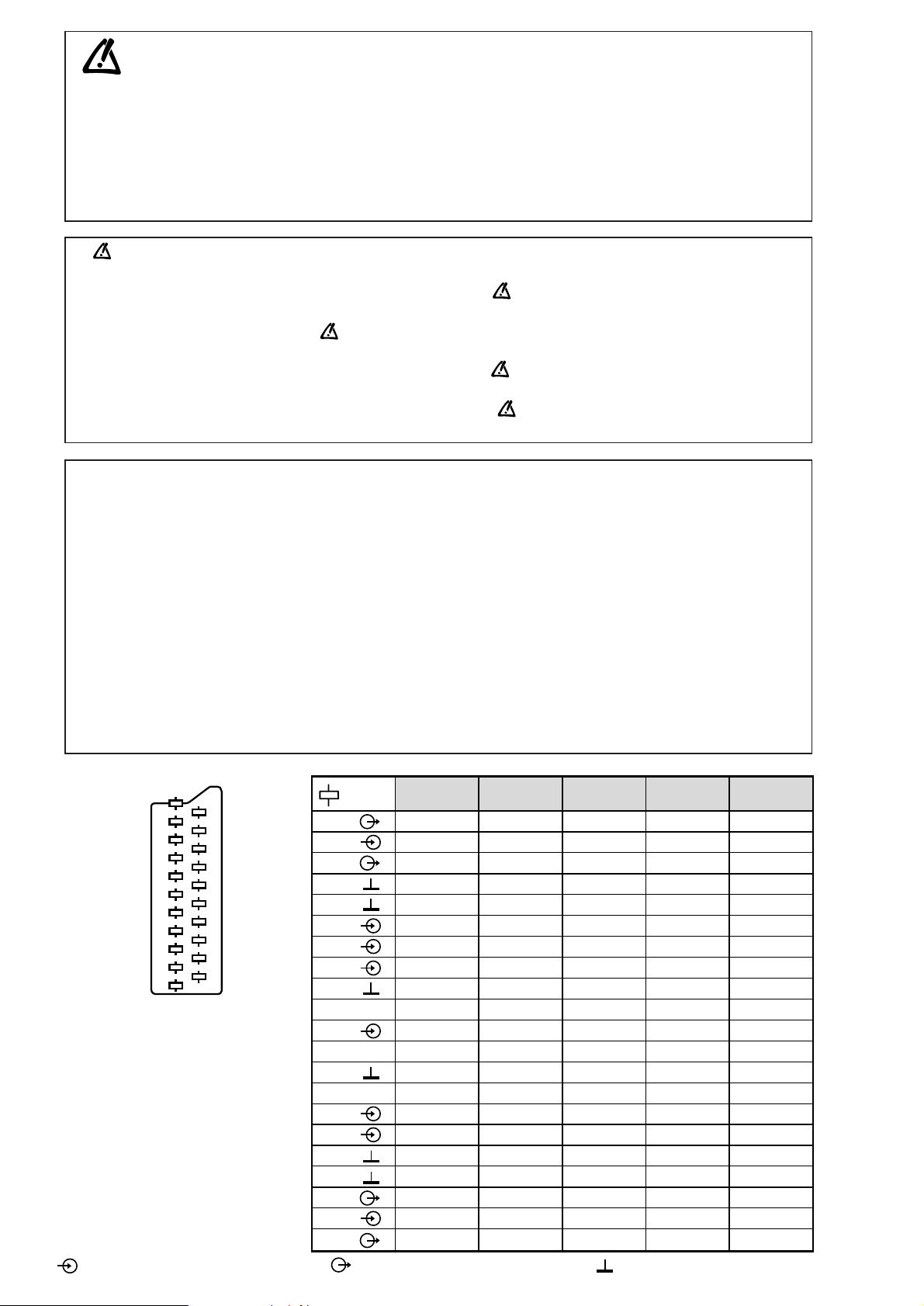
MAIN
FRANÇAIS ESPAÑOLDEUTSCHENGLISH ITALIANO
1
2
3
4
5
6
7
8
9
10
11
12
13
14
15
16
17
18
19
20
21
NC
NC
21
17
19
15
13
20
18
16
14
12
11
9
10
8
7
5
3
1
6
4
2
NC
AUDIO "R"
AUDIO "R"
AUDIO "L"
NOTE :
... etc. identifies each
pcb module.
AUDIO "D"
AUDIO "D"
AUDIO "G"
AUDIO
"BLEU"
AUDIO "G" MONO
"BLEU"
COMMUT. LENTE
"VERT"
"VERT"
"ROUGE"
COMMUT. RAPIDE
COMMUT. RAPIDE
VIDEO
VIDEO SYNCHRO
BLINDAGE PRISE
AUDIO "R"
AUDIO "R"
AUDIO "L"
AUDIO
"BLAU"
AUDIO "L" MONO
"BLAU"
AV
UMSCHALTUNG
"GRÜN"
"GRÜN"
"ROT"
AUSTASTUNG
AUSTASTUNG
VIDEO
VIDEO ODER
SYNCHRO
ABSCHIRMUNG
DES STECKERS
AUDIO "D"
AUDIO "D"
AUDIO "I"
AUDIO
"AZUL"
AUDIO "I" MONO
AZUL
"CONMUTACION
LENTA"
"VERDE"
"VERDE"
"ROJA"
"CONMUTACION
RAPIDA"
"CONMUTACION
RAPIDA"
VIDEO
VIDEO O SINCRO
BLINDAJE
DEL ENCHUFE
AUDIO "D"
AUDIO "D"
AUDIO "S"
AUDIO
"BLU"
AUDIO "S" MONO
BLU
"COMMUTAZIONE
LENTA"
"VERDE"
"VERDE"
"ROSSO"
"COMMUTAZIONE
RAPIDA"
"COMMUTAZIONE
RAPIDA"
VIDEO
VIDEO O SINCRO
INVOLUCRO METAL-
LICO DELLA PRESA
AUDIO "L" MONO
"BLUE"
"GREEN"
"GREEN"
"RED"
"ROUGE" "ROT" "ROJA""ROSSO""RED"
SLOW SWITCH
FAST SWITCH
VIDEO
VIDEO VIDEO VIDEOVIDEOVIDEO
PLUG SCREEN
BOX
VIDEO OR "SYNC"
FAST SWITCH
AUDIO
"BLUE"
: OUTPUT - SORTIE - AUSGANG - USCITA - SALIDA •
: EARTH - MASSE - MASSE - MASSA - MASA
MAIN
NOTE :
... etc. repères des
platines constituant l'appareil.
MAIN
NOTA :
... etc. marcas de las
placas que constituyen el
aparato.
MAIN
NOTA :
... ecc. sigla delle
piastre dell' apparecchio.
MAIN
HINWEIS :
... usw. Kennzeichnung
der Platinen, aus denen das
Gerät zusammengesetzt ist.
: INPUT - ENTRÉE - EINGANG - ENTRATA - ENTRADA •
Indicates critical safety components, and identical components should be used for replacement. Only then can the
operational safety be garanteed.
Le remplacement des éléments de sécurité (repérés avec le symbole ) par des composants non homologués selon la
Norme CEI 65 entraine la non-conformité de l'appareil. Dans ce cas, la responsabilité du fabricant n'est plus engagée.
Wenn Sicherheitsteile (mit dem Symbol gekennzeichnet) nicht durch Original - Ersatzteile ersetzt werden, erlischt die
Haftung des Herstellers.
La sostituzione dei componenti di sicurezza (evidenziati con il segno ) con componenti non omologati secondo la
norma CEI 65 comporta la non conformitá dell'apparecchio. In tal caso è "esclusa la responsabilità " del costruttore.
La sustitución de elementos de seguridad (marcados con el simbolo ) por componentes no homologados segun la
norma CEI 65, provoca la no conformidad del aparato. En ese caso, el fabricante cesa de ser responsable.
MEASUREMENT CONDITIONS - CONDITIONS DE MESURES - MESSBEDINGUNGEN
CONDIZIONI DI MISURA - CONDICIONES DE MEDIDAS
RICEVITORE :
In UHF, livello d'entrata 1 mV, monoscopio barre :
- PAL, norma G. bianco 100%.
Via SCART, livello d'entrata 1 Vpp, monoscopio barre :
Colore, Contrasto, Luminositá media, Suono minimo.
Programma selezionato PR 01.
Tensioni continue rilevate rispetto alla massa con un voltmetro digitale.
RECEIVER :
On UHF,input level : 1 mV, bar test pattern :
- PAL, I standard, 100% white.
Via the scart socket, input level : 1 Vpp, bar test pattern :
Colour, contrast and brightness at mid-position, sound at minimum.
Programme selected : PR 01.
DC voltages measured between the point and earth using a digital
voltmeter.
EMPFÄNGER :
Bei UHF Eingangspegel 1 mV, Farbbalken :
- PAL, Norm G, Weiss 100%.
Über die Scartbuchse : Eingangspegel 1 Vss, Farbbalken :
Farbe, Kontrast, Helligkeit in der Mitte des Bereichs, Ton auf Minimum.
Zugeordnetes Programm PR 01.
Gleichspannungen mit einem digitalen Voltmeter zur Masse gemessen.
RECEPTEUR :
En UHF, niveau d'entrée 1 mV mire de barres
- SECAM, Norm L, Blanc 100%.
Par la prise Péritélévision, niveau d'entrée 1 Vcc, mire de barres .
Couleur, contraste, lumière à mi-course, son minimum.
Programme affecté PR 01.
Tensions continues relevées par rapport à la masse avec un
voltmètre numérique.
RECEPTOR :
En UHF, nivel de entrada 1 mV, mira de barras :
- PAL, norma G, blanco 100%.
Por la toma Peritelevision, nivel de entrada 1 Vpp mira de barra.
Color, Contraste, luz a mitad de carrera, Sonido minimo.
Programa afectado PR 01.
Tensiones continuas marcadas en relacion a la masa con un voltimetro digital.
Do not disconnect modules when they are energized!
Repairs on power supply section are to be carried out only with isolating transformer.
Ne pas retirer les modules lorsqu' ils sont sous tension. N'effectuer les travaux de maintenance sur la partie reliée
au secteur (Switch Mode) qu'au travers d'un transformateur d'isolement.
Module nicht bei eingeschaltetem Gerät entfernen!
Servicearbeiten am Netzteil nur unter Verwendung eines Regeltrenntrafos durchführen.
Non scollegare le piastre quando sono alimentate!
Per le riparazioni sulla sezione alimentatore, utilizzare un trasformatore isolatore.
No desconectar los módulos cuando están activados. Las reparaciones en la sección de alimentación de energía
deben ser ejecutadas solamente con un transformador de separación.
Page 3

First issue 04 / 02 3
Page
DISASSEMBLING THE MODULES
Removing the optional speaker . . . . . . . . . . . . . . . . . . . . . . . . . . . . . . . . . . . . . . . . . . . . . . . . . . 4
Removing the back panel . . . . . . . . . . . . . . . . . . . . . . . . . . . . . . . . . . . . . . . . . . . . . . . . . . . . . . 4
Removing the front panel . . . . . . . . . . . . . . . . . . . . . . . . . . . . . . . . . . . . . . . . . . . . . . . . . . . . . . 5
Removing the fans . . . . . . . . . . . . . . . . . . . . . . . . . . . . . . . . . . . . . . . . . . . . . . . . . . . . . . . . . . . 6
Removing the chassis assembly . . . . . . . . . . . . . . . . . . . . . . . . . . . . . . . . . . . . . . . . . . . . . . . . . 6
Removing the PDP module . . . . . . . . . . . . . . . . . . . . . . . . . . . . . . . . . . . . . . . . . . . . . . . . . . . . .7
Removing the optical Filter . . . . . . . . . . . . . . . . . . . . . . . . . . . . . . . . . . . . . . . . . . . . . . . . . . . . .8
Removing the power module . . . . . . . . . . . . . . . . . . . . . . . . . . . . . . . . . . . . . . . . . . . . . . . . . . .8
Removing the flat cables . . . . . . . . . . . . . . . . . . . . . . . . . . . . . . . . . . . . . . . . . . . . . . . . . . . . . . . 9
BOARD LOCATION . . . . . . . . . . . . . . . . . . . . . . . . . . . . . . . . . . . . . . . . . . . . . . . . . . . . . . . . . . . . . . . . . .9
WIRING DIAGRAM . . . . . . . . . . . . . . . . . . . . . . . . . . . . . . . . . . . . . . . . . . . . . . . . . . . . . . . . . . . . . . . . . 10
DIAGNOSTIC . . . . . . . . . . . . . . . . . . . . . . . . . . . . . . . . . . . . . . . . . . . . . . . . . . . . . . . . . . . . . . . . . . . . . 11
BLOCK DIAGRAMS
Power supply . . . . . . . . . . . . . . . . . . . . . . . . . . . . . . . . . . . . . . . . . . . . . . . . . . . . . . . . . . . . . . 12
General . . . . . . . . . . . . . . . . . . . . . . . . . . . . . . . . . . . . . . . . . . . . . . . . . . . . . . . . . . . . . . . . . . . .13
ADJUSTMENTS
Mode service . . . . . . . . . . . . . . . . . . . . . . . . . . . . . . . . . . . . . . . . . . . . . . . . . . . . . . . . . . . . . . .14
Fixed data . . . . . . . . . . . . . . . . . . . . . . . . . . . . . . . . . . . . . . . . . . . . . . . . . . . . . . . . . . . . . . . . . . 14
White balance . . . . . . . . . . . . . . . . . . . . . . . . . . . . . . . . . . . . . . . . . . . . . . . . . . . . . . . . . . . . . . . 14
PDP power supply . . . . . . . . . . . . . . . . . . . . . . . . . . . . . . . . . . . . . . . . . . . . . . . . . . . . . . . . . . .14
Adjustment table . . . . . . . . . . . . . . . . . . . . . . . . . . . . . . . . . . . . . . . . . . . . . . . . . . . . . . . . . . . . 15
CONTENTS
Page 4
DISASSEMBLING THE MODULES
4 First issue 04 /02
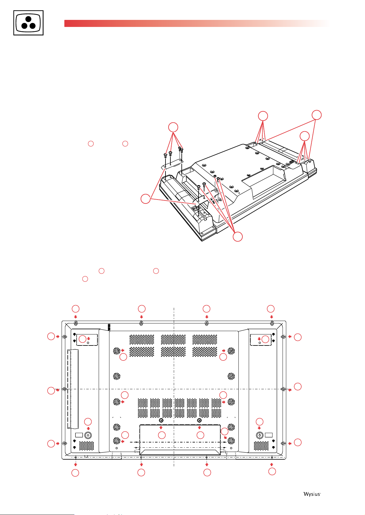
1. Removing the optional speaker
- Put the PDP Monitor Display with the screen face down on
the flat desk.
CAUTION : When placing the display with the face down,
lay the soft cloth under the screen to protect the screen
surface. And make sure there is nothing to damage the
screen surface like a screw or small part near by before
placing the display.
- Remove speaker lead wires (R & L).
- Remove 16 Screws and 4 plates . (Fig. 1)
2. Removing the back panel
- Remove the 14 screws (4X8),the 10 screws (5X8)
and the 2 screws (3X8).
- Remove the back panel.
0504030201
01
02
02
01
01
01
03 03 03 03
03
03
03
03
0303
03
03
03
03
04
04
0404
0404
04
0404
04
05
05
Page 5
First issue 04 / 02 5
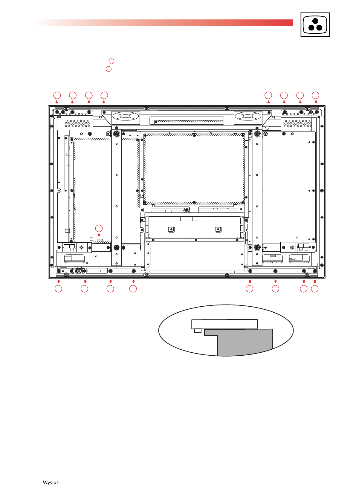
3. Removing the front panel
- Remove the 16 screws (4X8),
- Remove the flat cable from button unit to audio unit.
- Lift the chassis assembly up from the front panel and place
it the face down to the desk on soft cloth.
ATTENTION:
This PDP monitor is used the different kind of screw. Using
correct screw is needed to avoid the damage.
ATTENTION:
As R/C Pre-amp is projected from surface of the panel, it is
necessary to place it out of desk as shown below.
07
06
06
06 06 06 06 06 06 06 06
06 06 06 06 06 06
07
06
R/C Pre-amp
Front panel
Desk
Page 6
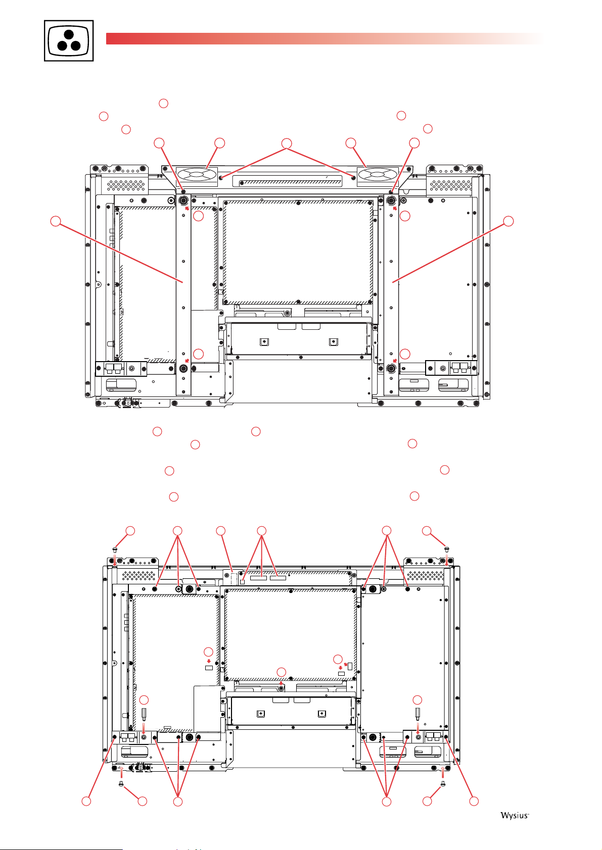
4. Removing the chassis assembly
- Remove the 2 screws (4X8 + 2 washers) and the 2
screws (3X6)
- Remove fans with holder plate.
- Remove the 14 screws (6X12) and the 4 screws (5X8),
- Remove the 2 hexagonal screws
,
- Slightly lift the chassis up,
- Disconnect the lead wire between main unit and panel
module from panel module side,
- Remove the fixing screw of the 2 yellow-green wires
(ground) from AC power connector and Panel Module,
- Remove the 4 screws (5X40)
- Remove the panel holders and the spacers located
between holder and module.
- Disconnect the lead wire between Audio Unit and panel
module from panel module side,
- Disconnect the 3 connectors (KPOW2, K6U and
KPOW3) from power unit,
- Disconnect the connector (KSENS1) of sensor unit,
- Lift the chassis assembly up from panel module.
20
19
18
12
11
17
1615141310
09
08
09
11
11
11
1212
11
08
10 10 08
1314 1419
18
16
17
15
14 14 1313
15
20
13
13
13
6 First issue 04 /02
Page 7

5. Removing the PDP module
- Remove the 2 screws ( 3X8) and the 3 screws
- Remove the power unit and the sensor unit with
holder plate from PDP module.
- Fix the 3 screws to PDP module after removing the
above mentioned units.
6. Removing the optical filter
The front cabinet includes optical filter to protect the panel
from damage, to improve picture quality, or prevent
exposure of interference.
- Remove the 4 screws ,
- Unscrew the 4 screws ,
- Remove the 6 screws ,
- Remove the 4 screws
- Remove 2 hexagonal screws to remove the PDP
module.
Note: cannot clean Panel surface or Optical Filter after
assembling Panel Module, if caught the dust to them.
25
29
282726
22
24
23
22
21
2324
22
22
21 21
22
2525
First issue 04 / 02 7
26 26 26 26
27 27 27 27
28
28
28
29
29
28
28
28
29
29
Page 8

- Remove the 6 screws and pull the top bracket,
- Remove the 4 screws and pull the right bracket,
- Remove the 6 screws and pull the bottom bracket,
- Remove the 4 screws and pull the left bracket,
7. Removing the power module
When replacing the PDP module, the power module must
be remove from the old PDP module and reassemble on the
new one. Proceed as follow:
- Remove the 7 screws (3x6),
Note:
The optical filter is easy to be damaged. Do not touch
directly by hand. If there is dust, remove it by watery
neutral detergent.
- Cut and remove the wire band ,
- Disconnect the wire from power module,
- Take out the power unit.
3536343833
323130
8 First issue 04 /02
30
Gasket
32
3133
34
34
34
34
35
34
34
34
36
37
38
Page 9

First issue 04 / 02 9
8. Removing the flat cables
This set use 3 kinds of connector for flat cable. To remove a
cable and not to damage it, proceed as below.
Type A:
- Lift up the hook on both sides and pull the flat cable to
disconnect it.
Type B:
- Slide the hook on both sides and pull the flat cable to
disconnect it.
Type C:
- Pull the flat cable to disconnect it.
BOARD LOCATION
MAINAUDIO
PC TERMINALPOWER SWITCH RC RECEIVER
SENSOR POWER
Cable
Cable
Cable
Type A
Type B
Type C
Page 10

WIRING DIAGRAM
10 First issue 04 /02
MTG FAN
CORE FERRITE
CORE FERRITE
CORE
FERRITE
CORE
FERRITE
CORE FERRITE
5
1
9V
6V
GND
34V
12V
12V
12V
GND
GND
GND
1
10
21
-5V
GND
31
5
51
1
NEUTLIVE
2
1
LIVE
NEUT
21
NEUT
LIVE
5050
50
501 1
11
12
12
10
10
10
1011
1
1
-5V
GND
GND
6V
9V
GND
GND
GND
12V
12V
12V
10
2
1
1
34V
GND
3.3VSTANBY
5VSTANBY51
AC(NEUT)
AC(LIVE)
370V
GND
6
331
1
FG
3
3
1
1
FG
363534333231302928272625242322212019181716151413121110
987654321
36353433323130292827262524232221201918171615141312111098765432
1
KRSPA
K16YA
CN1B
KGND2
KGND1
K3UA
KPOW3A
KSP901A
KSP902A
LF901A
CN1A
CN1-K7S
K3U-K6U
KPOWER3
K3T-K8T
KPOW2
K3D-8D
K10A-8A
K10K-8K
K10C19C
K13N19N
EL901
EL902
FN901 FN902
K8WK19RC
K8PW
ACIN
LF901
M901
KPOW3
KPOWER3
K6C
K8W
K3ST
K19RC
K8PO2
KPOW2
KSENS1
KSEN1
KFAN2KFAN1
K19SWP
K8PW
K8T
K6U
K3U
K3T
K19C
K8K
K8D
K3D
K10C
K19N
K13N
K10K
CN62
CN61
CN63
CN1
KLSPKRSP
K16Y
K16Z
KPOWER1
K8X
K7S
K8A
K10A
AC cord
Noise
filter
1
1
+- +-
2019181716151413121110
9
2019181716151413121110
9
214
357
6
8
214
357
6
8
AUDIO
MAIN
PC
RC
SW
POWER
SW
SENSOR
LOGIC
BOARD
AC-DC
BOARD
DC-DC
FAN
Page 11

First issue 04 / 02 11
DIAGNOSTIC
This set is equipped with a self-diagnostic function to detect power, audio amplifier, temperature and fan default. The trouble can be
identified either by a flashing of the tricolour led or by a message displayed on screen.
Start
Stop
The set switches
in standby mode
Does the message
"Warning! Internal fan
is trouble, not working
properly" appears on
screen for 10 seconds
every 10 minutes?
Is the power LED
flashing yellow
once?
Is the power LED
flashing red twice?
Is the power
LED flashing
green twice?
Failure in fan's
peripheral area
of the set
Check IC071 and
its peripheral
components
on AUDIO PCB
Check Fan and
Sensor control
circuit (IC1821)
on AUDIO PCB
Check 9V, 12V
and 30V lines
on AUDIO PCB
Check 9V, 12V
and 30V lines
on AUDIO PCB
Is the power
LED flashing green
three times?
No
No
Yes
Yes
No
Yes
No
Yes
Yes
Does the set switch
off, after displaying the
message:"Warning! Internal
temperature is too high"
for 10 seconds?
Temperature fail
No
Yes
Check 5V line on AUDIO
PCB and 3.3V, 2.5V and
2.5VST lines on MAIN PCB
Is the power
LED flashing
green once?
No
No
Yes
: Power Fail Line 3.
: Power Fail Line 1.
(see next page)
}
Notes:
In case of overlapped fails, flashing sequences are repeated in turn.
If power fail is detected 3 times in 15 minutes, the monitor will stop operating.
If the AC cord is unplugged, the information of fails will disappear.
Page 12

12 First issue 04 /02
POWER BLOCK DIAGRAM
Page 13

First issue 04 / 02 13
PC
R
G
B
MAIN
R
G
B
IC1124
RGB SWITCH
IC207
A/D CONVERTER
IC601
RGB MATRIX
IC301
MAIN SCALER
IC751
LVDS
INTERFACE
PDP
PANEL
MODULE
RGB
RGB
RGB
RGB
1(R)
3(
G)
5(
B)
7(R)
15(G)
22(B)
21
19
15
RGB
PC
DVI
IC1301
RGB
RGB
R/L
AUDIO
IC001
AUDIO CONTROL
(Fixed)
22(L),21(R)
16(L),15(R)
25(L),20(R)
23(L),22(R)
IC071
MAIN DIGITAL
AMP
+
-
L
R
SPEAKER X2
10(L),13(R)
*
Depending on DVI version, this audio line is bypassed to avoid the Audio Control IC.
GENERAL BLOCK DIAGRAM
Page 14

14 First issue 04 /02
It is necessary to enter the Service Mode in order to carry out
alignment of the set. Most adjustments must be made with
the RCU.
The following operations must be done quickly:
• Switch the monitor on,
• Press and hold the MENUbutton on the monitor,
• Using the remote control, press the EXIT button and
release it.
• Release the MENU button of the monitor.
• Press the MUTE button.
• The service mode menu appears on the screen.
Using the remote control:
• Press the / buttons to select the adjustment.
• Press the button to select the value of the adjustment.
• Press the / buttons to adjust the value.
• Press the button to select the name of another adjustment.
NB : the value of the adjustment is memorized automatically
into a non volatile memory.
• To exit the service mode menu press the power ON/OFF
button on the monitor.
ACCESSING SERVICE MODE
3
EXITING FROM SERVICE MODE
2
NAVIGATION INSIDE THE SERVICE MODE
MENU
OK
INPUT
VOLUME
MENU Button
Main
Sub
32
035
019
PDP Time
001396
Feb-Dynamic
Cont0 63 (3F)
Main
Sub
32
035
019
PDP Time
001396
Feb-Dynamic
Cont0 63 (3F)
Main
Sub
32
035
019
PDP Time
001396
Feb-Dynamic
Cont0 63 (3F)
SERVICE MODE
1
ADJUSTMENTS
All circuits have been adjusted in factory to make the monitor operating basically. These adjustments are controlled by the CPU
(IC801) and memorizzed into the memory (IC808). When the audio board or the memory is replaced, the fixed data must be set and
the white balance adjusted.
1. Setting the fixed data
- Make sure the received signal is good quality.
- Enter the service mode as above mentioned,
- Check the fixed data are corresponding to the data table
on next pages and adjust if necessary,
- Exit the service mode.
2. Adjusting the white balance
- Input signal 1.0Vpp/75 Ω terminated,
- White pattern,
- Screen size : full,
- Picture image level : natural
- Enter the service mode,
- Select alternatively adjustment n°69 (Cont FEB - red),
n°70 (Cont FEB - green) and n°71 (Cont FEB - blue),
- Adjust alternatively to obtain a proper white balance,
- After adjustment, confirm the white balance with a normal
picture.
3. PDP power supply
The PDP module stores voltage information and send it to
the power supply assembly to obtain the best voltage.
Therefore it is not necessary to adjust the PDP power
supply.
Page 15

First issue 04 / 02 15
0 FEB-Dynamic Contrast 63 0 63 Picture Menu (Dynamic)
1 Brightness 31 0 63
2 Color 45 0 63
3 Tint 0 -31 32
4 --------------- -- -- -5 FEB-Standard Contrast 50 0 63 Picture Menu (Natural)
6 Brightness 31 0 63
7 Color 31 0 63
8 Tint 0 -31 32
9 --------------- -- -- -10 FEB-Cinema Contrast 31 0 63 Picture Menu (Cinema)
11 Brightness 31 0 63
12 Color 26 0 63
13 Tint 0 -31 32
14 --------------- -- -- -15 PC Graphic Contrast 63 0 63 Picture Menu (Graphic)
16 Brightness 31 0 63
17 Color 45 0 63
18 Tint 0 -31 32
19 --------------- -- -- -20 PC Standard Contrast 40 0 63 Picture Menu (Standard)
21 Brightness 31 0 63
22 Color 31 0 63
23 Tint 0 -31 32
24 --------------- -- -- -25 PC-Text Contrast 31 0 63 Picture Menu (Text)
26 Brightness 31 0 63
27 Color 26 0 63
28 Tint 0 -31 32
29 --------------- -- -- -30 Sub Menu FEB Contrast 60h 00h FFh FEB Input
31 Brightness 39h 00h FFh
32 Color-S 78h 00h FFh S-Video
33 --------------- -- -- -34 Tint 00h 80h 7Fh
35 --------------- -- -- -36 Sub Menu PC Contrast 60h 00h FFh
37 Brightness 39h 00h FFh
38 Color-S 80h 00h FFh
39 Tint 00h 80h 7Fh
40 --------------- -- -- -51 Color Temp H-FEB Red DCh 00h FFh FEB Color Temperature (High)
52 Green F0h 00h FFh
53 Blue FFh 00h FFh
54 Color Temp M-FEB Red FFh 00h FFh FEB Color Temperature (STD)
55 Green FFh 00h FFh
56 Blue FFh 00h FFh
57 Color Temp L-FEB Red FFh 00h FFh FEB Color Temperature (Low)
58 Green EBh 00h FFh
59 Blue CDh 00h FFh
60 Color Temp H-PC Red DCh 00h FFh PC Color Temperature (High)
61 Green F0h 00h FFh
62 Blue FFh 00h FFh
63 Color Temp M-PC Red FFh 00h FFh PC Color Temperature (STD)
64 Green FFh 00h FFh
65 Blue FFh 00h FFh
No.
NoteAdjustment Name
Data Area
Adjustment Item
Initial
Data
Min Max
All data except in gray box area is fixed. Do not change for correct operating.
Data in gray box area is initial. Can be set according to adjustment information.
Page 16

16 First issue 04 /02
66 Color Temp L-PC Red FFh 00h FFh PC Color Temperature (Low)
67 Green EBh 00h FFh
68 Blue CDh 00h FFh
69 Cont FEB Red FFh 00h FFh White Balance Adjustment
70 Green F4h 00h FFh
71 Blue D2h 00h FFh
72 Bright FEB Red 80h 00h FFh Black Balance Adjustment
73 Green 80h 00h FFh
74 Blue 80h 00h FFh
75 Cont PC Red 00h 00h FFh W/B (Differential Data to FEB)
76 Green 00h 00h FFh
77 Blue 00h 00h FFh
78 Bright PC Red 00h 00h FFh B/B (Differential Data to FEB)
79 Green 00h 00h FFh
80 Blue 00h 00h FFh
93 Sharpness-PC Sharpness 0 0 10 Filter
94 Sharpness-FEB1-50 Sharpness 10 0 10 Filter
95 Sharpness-FEB1-60 Sharpness 6 0 10 Filter
111 PDP COLOR8 PDP Internal Pattern Display ( Key)
112 PDP WHITE PDP Internal Pattern Display ( Key)
113 Side Bar 81 0 225 Brightness od Side Bar
No.
NoteAdjustment Name
Data Area
Adjustment Item
Initial
Data
Min Max
Page 17

The description and characteristics given here are of informative significance only, and non committal. To keep up the high quality of our products, we reserve the right to
make any changes or improvement without previous notice. • Les descriptions et caractéristiques figurant sur ce document sont données à titre d'information et non
d'engagement. En effet, soucieux de la qualité de nos produits, nous nous réservons le droit d'effectuer, sans préavis, toute modification ou amélioration. • Die
Beschreibungen und Daten in dieser Anleitung dienen nur zur Information und sind nicht bindend. Um die Qualität unserer Produkte ständig zu verbessern, behalten wir uns
das Recht auf Änderungen vor. • Le descrizioni e le caratteristiche date su questo documento sono fornite a semplice titolo informativo e senza impegno. Ci riserviamo il
diritto di eseguire, senza preavviso, qualsiasi modifica o miglioramento. • Las descripciones y características que figuran en este documento se dan a título de información y
no de compromiso. En efecto, en bien de la calidad de nuestros productos, nos reservamos el derecho de efectuar, sin previo aviso, cualquier modificación o mejora.
THOMSON multimedia Sales Europe - S.A. au capital de 30 000 000 - Siège : 46, quai Alphonse Le Gallo 92100 Boulogne France - RCS Nanterre B 322 019 464
THOMSON multimedia
Sales France
46, quai Alphonse Le Gallo
92648 Boulogne cedex
Tel. : 01 41 86 60 00
Minitel : 3616 ou 3623 TCEDS
Internet : http://www.thomson.fr
THOMSON multimedia
Sales UK Limited
30 T ower Vie w
Kings Hill, West Malling
Kent ME19 4NQ (England)
Tel. : 44 (0) 173 252 0920
THOMSON multimedia
Sales Italy S.p.A.
Via Leonardo da Vinci,43
20090 Trezzano sul naviglio (Milano)
Tel. : (02) 48 414 111
THOMSON multimedia
Scandinavia AB
Florettgatan 29 C
S-25467 Helsingborg (Sweden)
Tel. : 042 25 75 00
THOMSON multimedia
Switzerland
Seewenweg 5
CH-4153 Reinach
Tel. : (61) 716 96 60
THOMSON
Consumer Electronics Poland
ul.Gen.L. Okulickiego 7/9
05-500 Piaseczno (Varsovie)
Tel. : (22) 757 10 80
THOMSON multimedia
Hungary KFT
Lajos u. 78. II.em.
H-1036 Budapest
Tel. : 00 36 14 5334/80
THOMSON multimedia
Czech s.r.o.
ul. Dopravaku - dum Genius 1
Dolni Chabry
CZ - 18400 Prague 8
Tel. : (2) 688 67 70
THOMSON multimedia
Sales Germany GmbH & Co oHG
Karl-Wiechert-Allee 74
30625 Hannover
THOMSON multimedia
Sales Spain
Avenida Isla Graciosa, 1
Edificio Áncora
Parque Empresarial La Marina
28700 San Sebastián de los Reyes (Madrid)
Tel. : (91) 384 14 19
THOMSON multimedia
Sales Portugal
Avenida da Boavista, 3521
4106 Porto
Tel. : (2) 26 18 76 41
This technical documentation is for use by maintenance technicians only
Documentation technique exclusivement destinée aux professionnels de la maintenance
Diese Angaben und Hinweise sind ausschließlich für den Service des Fachhändlers bestimmt
Documentazione tecnica destinata esclusivamente ai tecnici dell'assistenza
Documentación técnica destinada exclusivamente a los profesionales de mantenimiento
 Loading...