

Thomas & Betts Russellstoll Selection Guide
MaxGard® Interconnection Systems
30A–400A Plugs, Connectors, Receptacles, Inlets and Interlocked Receptacles
Russellstoll
Receptacles, Plugs and Connectors
FEATURE RUSSELLSTOLL MAXGARD
Center ground contact Yes No No
24 single-rated factory polarizations Yes No No
Gated deadfront construction Yes No No
Two optional control contacts Yes No No
Marine-grade CDA485 brass pins/sleeves Yes No No
(200–400 amp silver-plated)
O-rings/environmental separation, full line Yes No No
Available to 5-wire (4-pole, 5-wire) Yes 30 and 60 amp only No
Complete line epoxy powder coated — standard Yes No Some
®
CROUSE-HINDS ARKTITE®** APPLETON POWERTITE®***
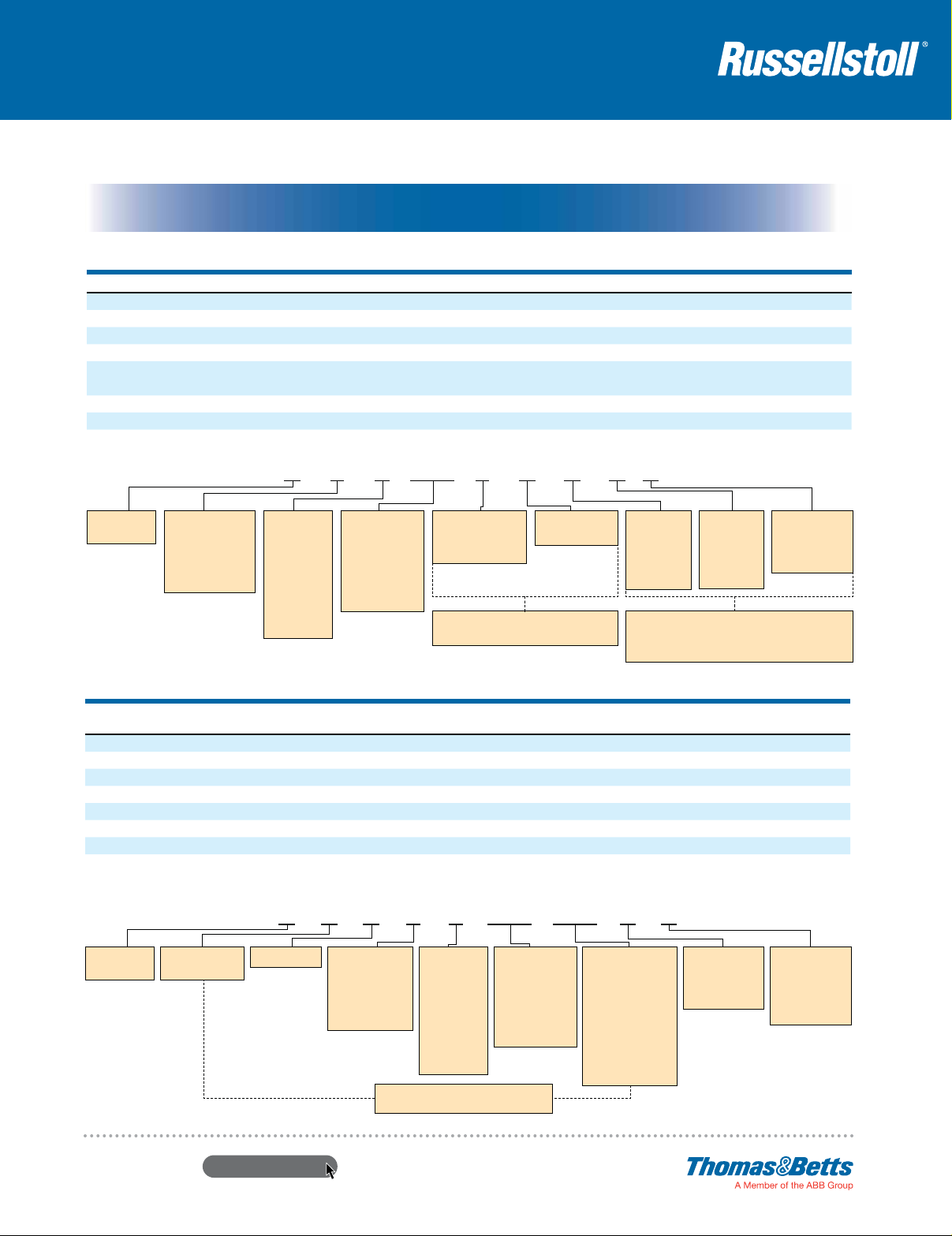
D F 3 414 F R A B K
D = Gated
Deadfront
F = Flap Cover
S = Screw Cover
(screw collar for
male plugs and
male inlets)
Amperage
Rating
3 = 30A
6 = 60A
1 = 100A
2 = 200A
4 = 400A
Voltage
Assignment
Number
See page 40
(Voltage
Selection chart)
M =
Male Pins
F =
Female Sleeves
(contacts)
Receptacle
R =
Plug
P =
Ex: FP = Connector
MR = Motor Inlet
Without
Ø
=
Adapter
Angle
A =
Straight
S =
Adapter
For last 3 positions above, Ø can appear in any
position. Standard plugs, etc. will have a ØØØ suffix,
Interlocked Receptacles
FEATURE RUSSELLSTOLL DBRE/DSRE SERIES CROUSE-HINDS EPC SERIES
Waterproof (DurORing™) O-ring sealing Yes No No
Available to 5-wire (4-pole, 5-wire) through 100 amp Yes No No
Gated deadfront Yes No No
Center ground sleeve contact Yes No No
24 single-rated factory polarizations Yes No No
Class I, Div. 1, Groups B, C, D Yes Yes Yes
Class II, Div. 1, Groups F and G Yes Yes Yes*
Meets Coast Guard (was CG259) approvals Yes No No
* Group F excepting electrically conductive dusts. ** Crouse-Hinds and Arktite are trademarks of Cooper Industries, Inc. *** Appleton and Powertite are trademarks of Appleton Electric Inc.
Ø = No Box
B = Junction
Box
E = Angle
Enclosure
(ex. DS2404MPØØØ).
APPLETON EBR SERIES
(WITH FB BREAKER)
Ø = Standard
K = 2 Control
Configuration
Contacts
®
Pin and Sleeve Power Connectors
D = Gated
Deadfront
S* = Switch
B = Circuit Breaker
www.tnb.com
D B R E 6 414 060 K S
R =
Receptacle
E = Explosion-Proof
F = Flap Cap
(weathertight)
S = Screw Cap
(watertight)
Amperage
Rating
3 = 30A
6 = 60A
1 = 100A
2 = 200A
4 = 400A
* With S in position 2, positions 9, 10 and
11 must be NAO (Non-Automatic Switch).
United States
Tel: 901.252.8000
800.816.7809
Fax: 901.252.1354
Voltage
Assignment
Number
See page 40
(Voltage
Selection chart)
Technical Services
Tel: 888.862.3289
Breaker
Rating or
Switch Code
See individual
product pages
for possible
breaker ratings
and codes
Ø = Standard
Configuration
K = 2 Control
Contacts
Ø = Standard
Configuration
S = Auxiliary
Switch
Z = Shunt Trip
13
 Loading...