


C E R T I F I E D
INDOOR OR OUTDOOR, GAS, DIRECT-FIRED, MAKEUP AIR/
HEATING SYSTEMS
(Specifications subject to change without notice.)
Operation/Maintenance/Service
Form RZ-NA 441-OMS
Applies to: |
Model Series DV |
TABLE OF CONTENTS
Page |
Page |
|
|
Page |
|||
MAINTENANCE |
|
8. Temperature Limit Safety Controls ... |
5 |
|
•Manifold Arrangements ................. |
8 |
|
SECTION ...................... |
2-4 |
•Manual Reset Limit Control ........... |
5 |
|
•Gas Pressure Switches .................... |
8 |
|
Configuration |
2 |
•Emergency Cut Off Limit Control .. |
6 |
12. |
Outside Air Ambient Cutoff |
8 |
|
9. Air Pressure Switches |
6 |
||||||
Maintenance Schedule |
2 |
13. |
Door Switch |
9 |
|||
•Low Air Flow Switch |
6 |
||||||
1A. Blower Bearings |
3 |
14. |
Inlet Air Controls |
9 |
|||
•High Air Flow Switch |
6 |
||||||
1B. Blower Belts |
3 |
|
•Air Flow Dampers |
9 |
|||
•Bypass Damper (Optional) Air |
|
|
|||||
2. Filters |
3 |
|
|
•Damper Motor |
9 |
||
Flow Switches |
6 |
|
|||||
3. Manifold Gas Pressure |
3 |
|
•Potentiometer |
9 |
|||
10. Ignition System |
6 |
|
|||||
4. Air Pressure |
4 |
|
•Pressure Null Switch |
9 |
|||
11. Gas Train Including Direct-Fired |
|
|
|||||
5. Circuit Indicator Board (check lights) 4 |
|
|
•Photohelic Pressure Switch |
10 |
|||
Burner, Gas Control Systems, |
|
|
|||||
|
|
|
15. |
Dirty Filter Switch |
10 |
||
6. Main Burner and Pilot Assembly |
...... 4 |
Manifold Arrangements and Gas |
|
||||
OPERATION/SERVICE |
|
Pressure Switches ............................. |
7 |
16. |
Photoelectric Smoke Detector ....... |
10 |
|
|
•Direct-Fired Burner |
7 |
17. |
Firestat |
10 |
||
SECTION |
5-15 |
||||||
•Makeup Air Gas Control Systems |
7 |
18. |
Freezestat |
10 |
|||
|
|
||||||
Controls - Location ....................... |
5 |
•Electronic Modulation Gas Control |
|
19. Troubleshooting ............................. |
11 |
||
7. Electronic Circuit Board with |
|
Options AG30, AG31, AG32, |
|
|
Chart 1 - General Troubleshooting |
||
|
AG33, AG35, AG36 |
7 |
|
Guide (Check the diagnostic lights on |
|||
Diagnostic Lights |
5 |
|
|||||
•Electronic Modulation Gas Control |
|
|
the circuit board) |
|
|||
|
|
|
|
|
|||
|
|
Option AG37 ................................. |
7 |
Index ................................................... |
12 |
||
References: Installation Manual, Form RZ 441
Replacement Parts Manual, Form RZ 741
FOR YOUR SAFETY
WARNING: The use and storage of gasoline or other flammable vapors and liquids in the vicinity of this appliance is hazardous.
If you smell gas:
1.Open windows.
2.Don't touch electrical switches.
3.Extinguish any open flame.
4.Immediately call your gas supplier.
WARNING: Improper installation, adjustment, alteration, service, or maintenance can cause property damage, injury or death. Read the installation, operation, and maintenance instructions thoroughly before installing or servicing this equipment.
KEEP THIS BOOKLET FOR MAINTENANCE AND SERVICE REFERENCE.
Operating/Maintenance/Service Instructions
The information in this manual applies to Model Series DV, di- rect-fired heating/makeup air systems. As with any gas burning equipment, regular maintenance procedures are required to ensure continued safety, reliability and efficiency of the installation.
If service is required, this system should be serviced only by a qualified service person. Service information in this booklet is intended as a guideline for a qualified gas-fired equipment service person.
Mfg No. 161442 Page 1
DANGER: The gas burner in this direct gas-fired system is designed and equipped to provide safe and economically controlled complete combustion. However, if the installation does not permit the burner to receive the proper supply of combustion air, complete combustion may not occur. The result is incomplete combustion which produces carbon monoxide, a poisonous gas that can cause death.
Always comply with the combustion air requirements in the installation codes and operating instructions. The amount of air over the burner must be within the specified range. The burner profile plates are set at the factory to match CFM requirements. Do not adjust the burner profile plates without contacting the factory. FAILURE TO PROVIDE PROPER COMBUSTION AIR CAN RESULT IN A HEALTH HAZARD WHICH CAN CAUSE PROPERTY DAMAGE, SERIOUS INJURY, AND/OR DEATH. Directfired installations should provide for air changes as required by the applicable installation codes.
Maintenance Section
This direct-fired makeup air system is designed to require only a minimum amount of maintenance. Some maintenance procedures outlined in this Section require inspection only and some require action. Frequency requirements of each maintenance procedure are listed in the Maintenance Schedule. Depending on the environment and the number of operating hours, more frequent inspection and/or cleaning may be required to certain components.
Although maintenance requirements are minimal, the routine maintenance procedures in this Section are necessary to ensure safe, reliable, and/or efficient operation. The paragraphs which follow discuss the components and systems that require routine inspection/maintenance. At the beginning of each paragraph, there is a code indicating why that maintenance procedure is necessary. The legend for that code is shown below.
Maintenance Codes
Reason for Maintenance
S = Safety (to avoid personal injury and/or property damage)
R = Continued Reliability
E = Efficient Operation
WARNING: Disconnect all power to the system before doing any maintenance. Failure to do so may cause electrical shock, personal injury, or death.
Maintenance Schedule
See Chart Lubricate bearings, Paragraph 1
Quarterly Check the filters, Paragraph 2
Check air pressure sensing tubes, Paragraph 4
Semi-Annually Check blower belts, Paragraph 1
Verify gas pressures, Paragraph 3
Clean air pressure sensing tubes, Paragraph 4
Check indicator lights, Paragraph 5
Annually Check main burner and pilot assembly, Paragraph 6
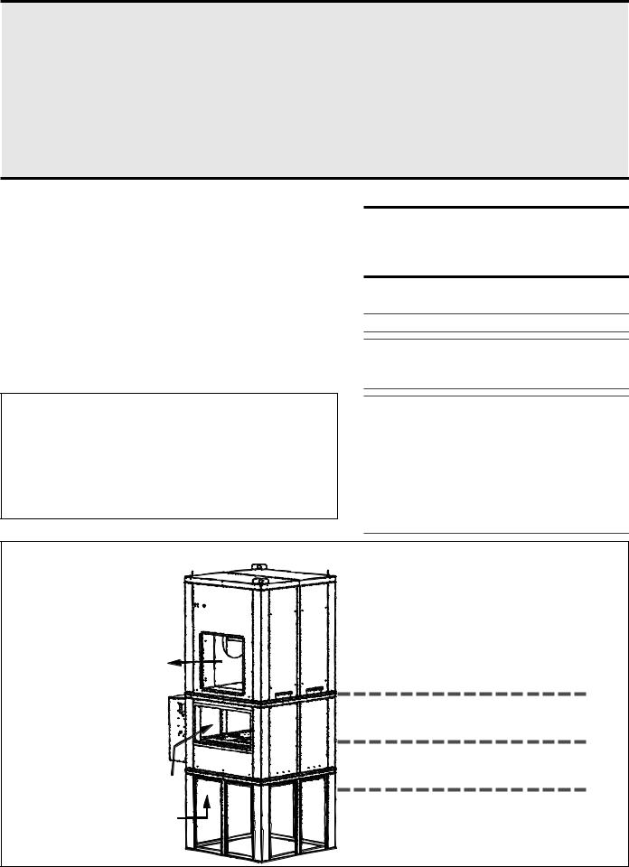
Figure 1 - System
Configuration
Discharge Air
Optional Return Air
Outside Air
Blower
Section
Burner/Control Section
Location of Optional Filter Cabinet (not shown)
Screened Inlet Base
Page 2

R 1. Drive Components
The blower, motor and drive components are located in the blower cabinet at the top of the system. Systems with horizontal discharge have a cabinet with eight removable door panels. Systems with vertical discharge have a cabinet with six removable door panels. Remove the panels required to access the components being serviced.
1A. Blower Bearings
All blowers are Class I with pillow block bearings. Clean the fitting and add type NLG-2 or -2 standard grade grease. Add grease with a handgun until a slight bead of grease forms at the seal. Be careful not to unseat the seal by over lubricating.
NOTE: If unusual environmental conditions exist (temperatures below 32oF or above 200oF; moisture; or contaminants) more frequent lubrication is required.
CAUTION: If the blower is unused for more than three months, the bearings should be purged with new grease prior to startup.
Recommended Bearing Lubrication Schedule in Months
|
Bearing Bore Diameter (Inches) |
||
RPM |
1/2 |
>1 to |
>1-1/2 to |
|
to 1 |
1-1/2 |
1-15/16 |
|
|
|
|
|
|
|
|
to 500 |
6 |
6 |
6 |
501 - 1000 |
6 |
6 |
6 |
1001 - 1500 |
5 |
5 |
5 |
1501 - 2000 |
5 |
4 |
5 |
1B. Blower Belts
Check belts for proper tension and wear. Adjust belt tension as needed. Replace worn belts.
Proper belt tension is important to the long life of the belt and motor. A loose belt will cause wear and slippage. Too much tension will cause
excessive motor and blower bearing wear. If adjustment is required, adjust belt tension by means of the adjusting screw on the motor base until the belt can be depressed 1/2" to 3/4" (Figure 2). Tighten the lock nut on the adjusting screw. Be sure the belt is aligned in the pulleys.
Figure 2 - |
|
|
Belt |
3/4” (19mm) |
|
Tension |
||
|
R 
 E 2. Filters
If the system includes filters, check the filters quarterly. Filters could be either in the optional inlet base or in an optional filter cabinet.
If the filters are in the perimeter of the inlet base; they are two-inch permanent filters. Remove and clean the filters as needed.
If the filters are in a filter cabinet (the filter cabinet is always between the inlet base and the burner/control section), remove the filter cabinet door panels to access the V-bank filter rack. Filters may be either 2" disposable, 1" or 2" permanent, or 1" or 2" disposable pleated. Clean or replace as needed.
Sizes and Quantity of Filters in the Filter Cabinet ( same for all types of filters)
Size |
109 |
112 |
115 |
118 |
122 |
125 |
16" x 16" |
4 |
4 |
- |
- |
16 |
16 |
16" x 20" |
4 |
4 |
6 |
6 |
- |
- |
16" x 25" |
- |
- |
6 |
6 |
8 |
8 |
S 3. Manifold Gas Pressure
Semiannually, check the gas pressure to the burner and to the pilot. Measure both manifold pressure and pilot supply pressure with the blower in operation. Refer to Figure 3 for pressure tap locations. Verify against pressures listed on the rating plate.
Figure 3 - Location of
pressure taps for |
|
Pilot |
Pilot Solenoid Valve |
|
Pilot Manifold |
Regulator |
|||
measuring burner and |
||||
|
||||
|
|
|||
pilot gas pressure. |
|
|
|
|
Measure with blower |
|
|
Pilot Pressure Tap |
|
operating. |
|
|
|
Valve |
Valve |
Regulator |
Manifold Pressure Tap |
|
|
||
Gas |
|
|
|
Supply |
|
|
|
Inlet Pressure Tap |
|
|
|
Page 3
S 4. Air Pressure
Profile plate sensing tubes should be checked quarterly and cleaned no less than semiannually. If the sensing tubes become even partially blocked, false pressure readings may be relayed. To clean, remove the screened end caps. Clean the screens and the tubes, if necessary. Replace the cleaned end caps. Check the pressure differential across the profile plate using a slope gauge. Air pressure differential should be between -.5" and -.7" w.c.
To attach the slope gauge, open the control compartment door panel. Just below the junction box, locate the tubing connections. Remove the cap at each connection and attach the slope gauge using two fieldsupplied 1/4" x 1/8" female NPT barbed tubing connections. For instructions on measuring air pressure, see Service Section, Paragraph 9.
R |
5. Circuit Indicator Board (check |
|
lights) |
||
|
||
|
The circuit indicator board is located in the control compartment electrical box (See Figure 7). Check operation of all indicator lights by switching lights that are not lit with one that is currently lit. Replace all burned out indicator bulbs (P/N 125189).
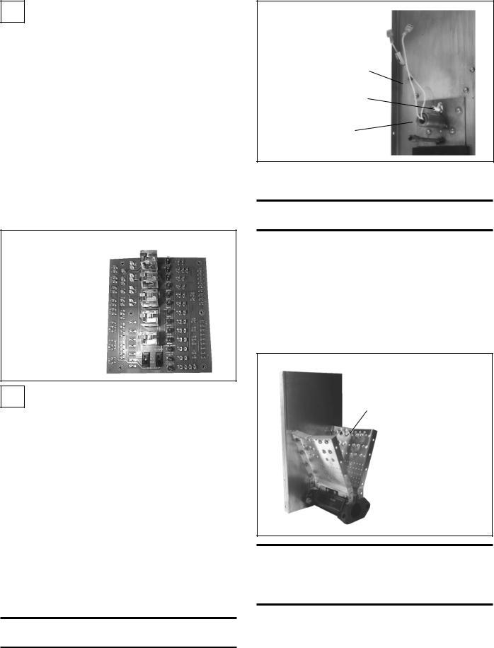
Figure 4 - Circuit |
Row of Bulbs |
|
Indicator Board, |
|
|
P/N 151263 |
|
|
Check bulbs not |
|
|
lit with other |
|
|
bulbs; replace |
|
|
any burned out |
|
|
bulbs |
|
|
S 6. Main Burner and Pilot Assembly
For the most part, the burner and pilot are self cleaning. However, if the application is extremely dirty or dusty, cleaning of the burner and pilot may be necessary. Inspect the burner annually. Follow these instructions. If it is necessary to replace any parts, use only factory-autho- rized replacements.
1)Turn off the gas and power supply to the system.
2)Remove the door panels in the burner/control cabinet (four or six depending on whether or not the system has return air). Locate the pilot.
3)Disconnect the two ignition wires (male and female quick connections) and disconnect the flame sensor lead at the burner. Remove the set screw located in the ignitor tube (set screw holds the brass bushing in place). Carefully remove the brass bushing and the ignitor.
Check the hot surface ignitor for cracks or unusual deterioration. Check the flame rod for integrity. Replace the flame rod (P/N 131188) and/or the hot surface ignitor (P/N 121865) if not in good condition.
4)Clean the burner and pilot by back-flushing, using high pressure air (40-80 lbs). Continue until dust particles are completely expelled from both the upstream and downstream sides of the burner.
CAUTION: Wear eye protection while pressure cleaning and drilling.
Figure 5 - Burner
End Plate showing
Hot Surface Ignitor
Burner End Plate
Flame Sensor
Ignitor
If air pressure does not unplug burner orifices or pilot tube, drill burner orifices with a Size #50 drill and/or pilot tube with a Size #55 drill.
WARNING: Do not enlarge burner ports or performance may be drastically affected.
Inspect the upstream and downstream sides of the mixing plates. Remove any accumulation of scale or foreign material with a wire brush. If any mixing plate fasteners are loose or missing, tighten or replace. Always use zinc plated or stainless fasteners.
If any cracks are present, replace that mixing plate. Because of the effect of flame temperature on the metal, fasteners may be difficult to remove. Be careful not to damage the gaskets that go between the mixing plates and the burner body. The gaskets are designed to overlap approximately 1/16" for tight air seal.
5)Follow Steps in reverse order to re-install the pilot assembly. Close all panels and check for proper operation.
Figure 6 - Illustration of the first Burner Section
Mixing
Plate
Full length of the burner is made up of a series of 6" or 12" burner sections in a linear or oval configuration
 Burner
WARNING: Burner profile plates are factory set to match CFM requirements.
Do not adjust profile plates without contacting your Sales Representative for technical assistance.
Page 4
 Loading...