

Page 1

Bulletin 4390-974250
FluidConnectors
Cut 250 Saw Use and
Maintenance Manual
Part Number: 974250
Effective: September 1, 1999
Page 2

Bulletin 4390-974250
Cut 250 Saw Use and Maintenance Manual
FAILURE OR IMPR OPER SELECTION OR IMPROPER USE OF THE PR ODUCTS AND/OR SYSTEMS DESCRIBED HEREIN OR RELATED ITEMS CAN CA USE DEATH, PERSONAL
INJURY AND PROPERTY DAMAGE .
This document and other information from Parker Hannifin Corporation, its subsidiaries and authorized distributors provide product and/or system options for further investigation by
users having technical expertise. It is important that you analyze all aspects of your application and review the information concerning the product or system in the current product
catalog. Due to the va riety of operating conditions and applications for these products or systems , the user, through its own analysis and testing, is solely responsible for making the
final selection of the products and systems and assuring that all performance, safety and warning requirements of the application are met.
The products described herein, including without limitation, product features, specifications, designs, availability and pricing, are subject to change by Parker Hannifin Corporation
and its subsidiaries at any time without notice.
The items described in this document are hereby offered for sale by Parker Hannifin Corporation, its subsidiaries or its authorized distributors. This offer and its acceptance are
governed by the provisions stated in the "Offer of Sale".
FluidConnectors
WARNING
Offer of Sale
Parker Hannifin Corporation
Tube Fittings Division
Columbus, OH
Page 3

Bulletin 4390-974250
Contents
Cut 250 Saw Use and Maintenance Manual
Contents ............................................................................ 1
Ordering Spare Parts ....................................................... 1
Guarantee .......................................................................... 1
Machine Certification and Identification Marking ......... 2
CHAPTER 1______________________________________
Reference to Accident-Prevention Regulations ............ 3
1.1 – Advice for the operator ........................................... 3
1.2 – Location of shields against accidental contact with
the tool .................................................................... 3
1.3 – Electrical equipment according to European
Standard "CENELEC EN 60 204-1" (1992)............ 3
1.4 – Emergencies according to European Standard
CENELEC EN 60 204-1" (1992)............................. 3
CHAPTER 2______________________________________
Recommendations and Advice for Use .......................... 3
2.1 – Recommendations and advice
for using the machine ............................................. 3
CHAPTER 3______________________________________
Technical Characteristics ................................................ 4
3.1 – Table of cutting capacity and technical details ....... 4
CHAPTER 4______________________________________
Machine Dimensions – Transport –
Installation – Dismantling ................................................ 4
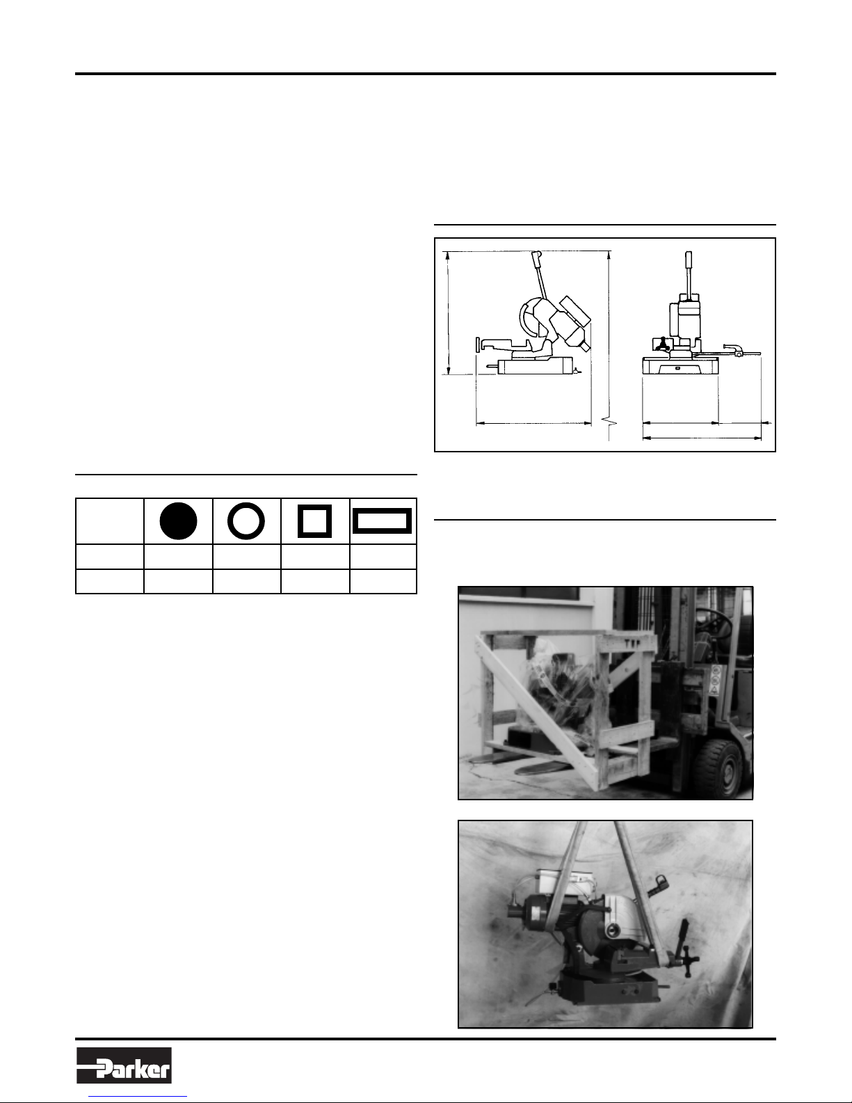
4.1 – Machine dimensions ............................................... 4
4.2 – Transpor t and handling of the machine .................. 4
4.3 – Minimum requirements for the premises
housing the machine .............................................. 5
4.4 – Anchoring the machine ........................................... 5
4.5 – Instructions for electrical connection ...................... 5
4.6 – Instructions for assembly of
the loose parts and accessories............................. 5
4.7 – Deactivating the machine ....................................... 5
CHAPTER 5______________________________________
Machine Functional Parts................................................ 5
5.1 – Operating head ....................................................... 5
5.2 – Vice ......................................................................... 6
5.3 – Bed .......................................................................... 6
CHAPTER 6______________________________________
Description of the Operating Cycle ................................ 6
6.1 – Starting up and cutting cycle .................................. 6
CHAPTER 7______________________________________
Regulating the Machine ................................................... 7
7.1 – Saw head ................................................................ 7
7.2 – Vice ......................................................................... 7
7.3 – Regulating arm blockage ........................................ 7
7.4 – Changing the blade................................................. 7
7.5 – Changing the lubricating coolant pump .................. 7
CHAPTER 8______________________________________
Routine and Special Maintenance .................................. 7
8.1 – Daily maintenance .................................................. 7
8.2 – Weekly maintenance .............................................. 7
8.3 – Monthly maintenance ............................................. 7
8.4 – Six-monthly maintenance ....................................... 8
8.5 – Oils for lubricating coolant ...................................... 8
8.6 – Special maintenance .............................................. 8
CHAPTER 9______________________________________
Material Classification and Choice of Tool ....................8
9.1 – Definition of materials ............................................. 8
9.2 – Choosing the blade................................................. 9
9.3 – Teeth pitch .............................................................. 9
9.4 – Cutting and advance speed.................................... 9
9.5 – Breaking in the blade .............................................. 9
9.6 – Type of blade ........................................................... 9
Tooth shape ............................................................ 9
Tooth cutting angle ................................................. 9
Sharpening circular saws ..................................... 10
9.6.1 – Table of recommended cutting parameters .......... 10
9.6.2 – Table of cutting speed according to
blade diameter ...................................................... 11
CHAPTER 10_____________________________________
Machine Components .................................................... 12
10.1 – List of spare parts ................................................. 12
CHAPTER 11_____________________________________
Wiring Diagrams ............................................................. 15
CHAPTER 12_____________________________________
Troubleshooting.............................................................. 17
12.1 – Blade and cut diagnosis ....................................... 17
12.2 – Electrical components diagnosis .......................... 19
CHAPTER 13_____________________________________
Noise T ests ...................................................................... 19
Plates and Labels ........................................................... 20
Offer of Sale .................................................................... 21
Ordering Spare Parts
• When ordering spare par ts you must state:
Machine model
Serial number
Part reference number
Without these references
See point 10.1 – List of spare parts.
we will not supply
FluidConnectors
the spare parts.
Guarantee
• The Company guarantees that the machine to which this
manual refers has been designed and built to comply with
safety regulations and that it has been tested for functionality in the factory.
• The machine is guaranteed for 12 months: the guarantee
does not cover the electric motors, electric components,
pneumatic components or any damage due to dropping or
machine misuse, the failure to observe maintenance standards or bad handling by the operator.
1
Parker Hannifin Corporation
Tube Fittings Division
Columbus, OH
Page 4

Bulletin 4390-974250
Cut 250 Saw Use and Maintenance Manual
Machine Certificaton and Identification
Machine Certification and Identification Marking
MACHINE LABEL
via Pasubio, 32 36033 ISOLA VIC. - ITALIA
MODEL
TYP
SERIAL NUMBER
YEAR OF MANUFACTURE
CUT 250
FluidConnectors
2
Parker Hannifin Corporation
Tube Fittings Division
Columbus, OH
Page 5

Bulletin 4390-974250
Cut 250 Saw Use and Maintenance Manual
Reference to Accident-
1
1.1 — Advice for the operator
•Check that the voltage indicated on the plate, normally fixed
•Check the efficiency of your electric supply and grounding
•When the tool head is in rest position (raised), the toothed
•It is not recommended to operate saw without its shields
•Always disconnect the power source before changing the
•It is not recommended to disconnect the “man present” de-
•Always wear eye protection.
•Never put your hands or arms into the cutting area while the
•Do not move the machine while it is cutting.
•Do not wear loose clothing , gloves that are too big, brace-
•Keep the area free of equipment, tools or any other object.
•Perform only one operation at a time and never have sev-
•All internal and/or external operations, maintenance or re-
1.2 — Location of shields against accidental
contact with the tool
Prevention Regulations
This machine has been built to comply with the national
and community accident-prevention regulations in force.
Improper use and/or tampering with the safety devices will
relieve the manufacturer of all responsibility.
to the machine motor, is the same as the line voltage.
system; connect the power cable of the machine to the socket
and the ground lead (yellow-green in color) to the ground
system.
blade must be stationary.
(these are all white, blue or grey in color).
blade or carrying out any maintenance job, even in the case
of abnormal machine operation.
vice, known more correctly in the EEC as the “safety switch
with hold-down action”.
machine is operating.
lets, chains or any other object that could get caught in the
machine during operation; tie back long hair.
eral objects in your hands at the same time.
pairs, should be performed in a well-lit area or where there
is sufficient light from extra sources so as to avoid the risk of
accidents.
1.3 — Electrical equipment according to
European Standard “CENELEC EN 60 204-1”
which assimilates, with some integrating
modifications, the publication “IEC 204-1
(1992)”
•The electrical equipment ensures protection against electric
shock as a result of direct or indirect contact. The active
parts of this equipment are housed in a box to which access
is limited by screws that can only be removed with a special
tool; the parts are fed with alternating current at low voltage
(24 V). The equipment is protected against splashes of water and dirt.
•Protection of the system against short circuits is ensured by
means of fuses and grounding; in the event of motor overload, protection is provided by a thermal probe.
•In the event of a power cut, the specific start-up button must
be reset.
•The machine has been tested in conformity with point 20 of
EN 60204.
1.4 — Emergencies according to European
Standard “CENELEC EN 60 204-1 (1992)”
•In the event of incorrect operation or of danger conditions,
the machine may be stopped immediately by pressing the
red mushroom button.
NOTE:Resetting of machine operation after each emergency
stop is achieved by reactivating the specific restart
button.
Recommendations
2
2.1 — Recommendations and advice for using
the machine
•The machine has been designed to cut tubing with different
•Only one operator is needed to use the machine.
and Advice for Use
shapes and profiles.
•Grey metal shield screwed onto the saw head.
•Self-regulating mobile blue plastic shield, fitted coaxially with
the fixed shield.
FluidConnectors
3
Parker Hannifin Corporation
Tube Fittings Division
Columbus, OH
Page 6
Bulletin 4390-974250
Cut 250 Saw Use and Maintenance Manual
•To obtain break-in of the machine it is advisable to start using it at intervals of about half an hour. This operation should
be repeated two or three times, after which the machine
may be used continuously.
•Before starting each cutting operation, ensure that the part
is firmly gripped in the vice and that the end is suitably supported.
•Do not use blades of a different size from those stated in the
machine specifications.
•If the blade jams in the tube, release the running button
immediately, switch off the machine, open the vice slowly,
remove the part and check that the blade or its teeth are not
broken. If they are broken, change the blade.
•Before carrying out any repairs on the machine, consult the
dealer or call Parker Tube Fittings Division.
Technical
3
3.1 — Table of cutting capacity
and technical details
Characteristics
Machine Dimensions –
4
Transport – Installation –
Dismantling
4.1 — Machine dimensions
800
1550 WITH PEDESTAL
940
410
770
360
Cutting
Capacity
90° 30 70 65 100 x 45
45° DX 25 60 55 65 x 150
•Three-phase el. motor for
2-speed blade rotation kW 0.75 ÷ 0.95
•Single-phase el. motor for
1-speed blade rotation kW 0.9
•Reduction gear in an oil bath Ratio=1:32
•Maximum blade diameter mm 250
•Blade rotation speed rpm 40 ÷ 80
•Vice opening mm 105
•Machine weight kg 80
4.2 — Transport and handling of the machine
If the machine has to be moved, use a fork-lift truck or sling it
with straps as illustrated.
FluidConnectors
4
Parker Hannifin Corporation
Tube Fittings Division
Columbus, OH
Page 7
Bulletin 4390-974250
Cut 250 Saw Use and Maintenance Manual
4.3 — Minimum requirements for the premises
housing the machine
• Main voltage and frequency complying with the machine motor characteristics.
• Environment temperature from -10°C to +50°C.
• Relative humidity not over 90%.
4.4 — Anchoring the machine
580
440
AA
560
270 290
• Position the machine base on a firm cement floor, maintaining, at the rear, a minimum distance of 800 mm from the
wall; anchor it to the ground as shown in the diagram, using
screws and expansion plugs or tie rods sunk in cement, ensuring that it is sitting level.
7070
M8
12
SEC. A - A
PEDEST AL PROFILE
4.5 — Instructions for electrical connection
• The machine may not be provided with an electric plug.
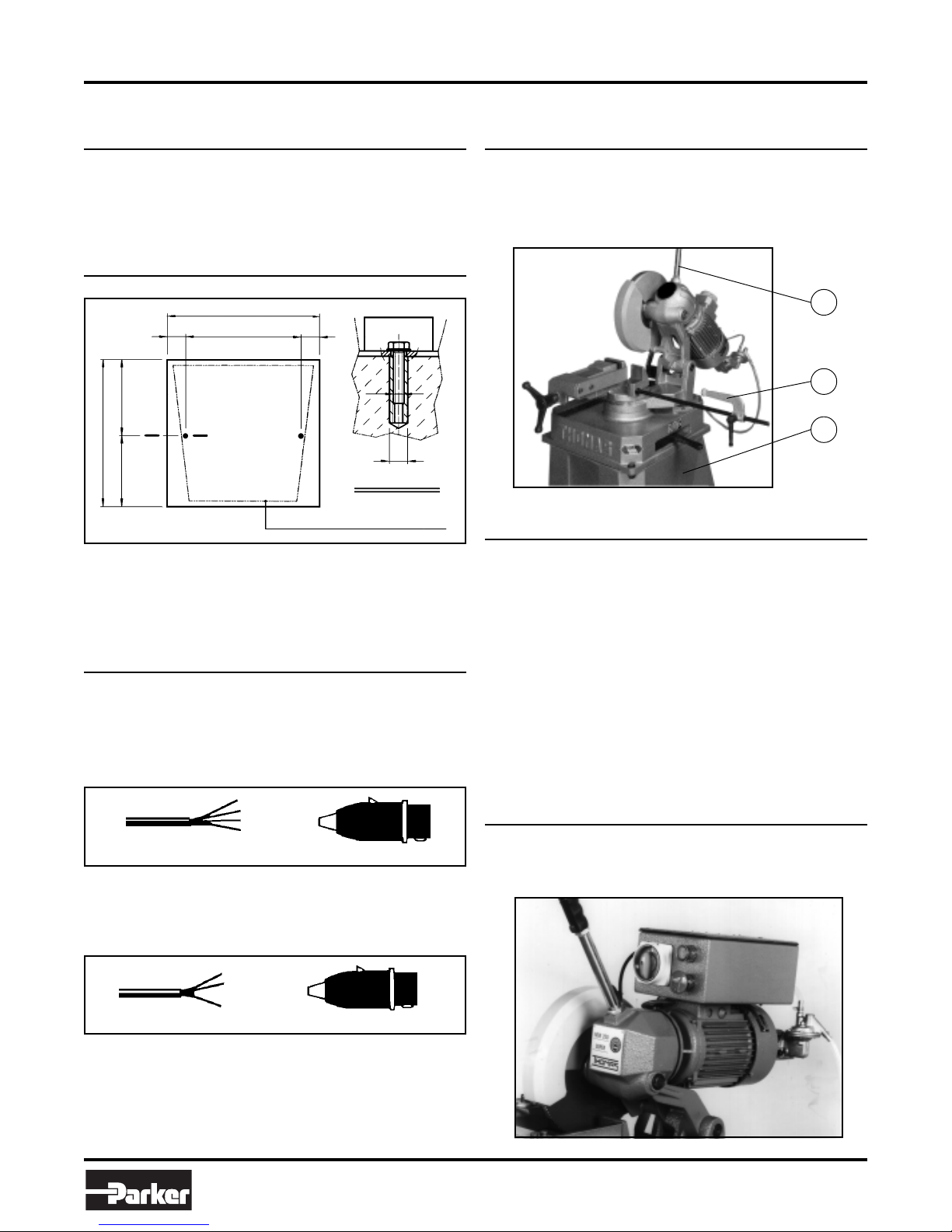
4.6 — Instructions for assembly of the loose
parts and accessories
Attach the components supplied as indicated in the photo:
• part. 1 Screw the lever onto the head
• part. 2 Attach the bar holding rod
• part. 3 Attach the pedestal fir mly onto the base
1
2
3
4.7 — Deactivating the machine
If the sawing machine is not to be used for a long period, it is
advisable to proceed as follows:
1) Detach the plug from the electric supply panel
2) Release the head return spr ing
3) Empty the coolant tank
4) Carefully clean and grease the machine
5) If necessar y, cover the machine.
1 – WIRING DIAGRAM FOR 5-WIRE SYSTEM WITH NEU-
TRAL FOR THREE-PHASE MACHINE - SOCKET FOR A
16A PLUG
R = L1
S = L2
T = L3
PE = GND
N = NEUTRAL
2 – WIRING DIAGRAM FOR THE SINGLE-PHASE SYSTEM
SOCKET FOR A 16A PLUG
= L1
= L2
= PE
FluidConnectors
Machine Functional Parts
5
5.1 — Operating head
• Machine part composed of the par ts that transmit movement (motor, reduction unit), the lubricating coolant pump
and the electrical components.
5
Parker Hannifin Corporation
Tube Fittings Division
Columbus, OH
Page 8
Bulletin 4390-974250
Cut 250 Saw Use and Maintenance Manual
5.2 — Vice
• System for gripping material during the cutting operation,
operated with handwheel.
Provided with an anti-burr device for holding the part that is
to be cut.
5.3 — Bed
• Suppor t structure for the OPERATING HEAD (rotating ar m
for gradual cutting, with respective blocking system), the
VICE, the BAR STOP, and the housing for the cutting coolant TANK.
Description of the
6
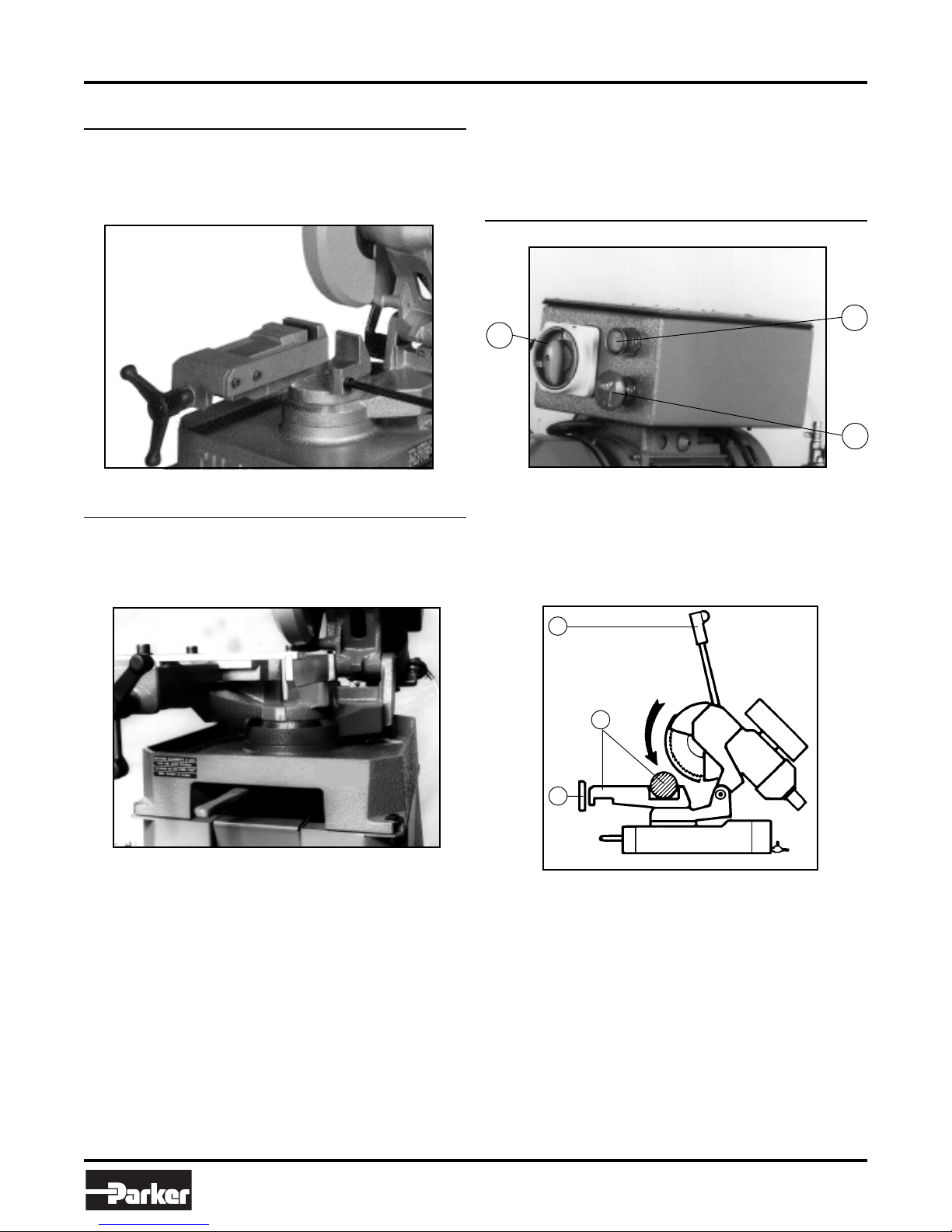
6.1 — Starting up and cutting cycle
3
• Ensure that the machine is not in emergency stop condition;
• Select the cutting speed on the switch (3):
• Press the star t/reset button (2): green light will go on.
Operating Cycle
2
1
if it is, release the red mushroom button (1).
position 1 = 40 rpm
position 2 = 80 rpm
6
4
5
• Place material to be cut in the vice (4) and clamp the par t
into place by handwheel (5).
• Grip the handle (6) of the HEAD control ar m and press the
button, checking that the blade is turning in the direction
indicated (if not, invert the two phase leads) and that sufficient coolant is flowing.
• When starting to cut with a new blade, in order to safeguard its life and efficiency, the first two or three cuts
must be made while exerting a slight pressure on the
part, so that the time taken to cut is about double the
normal time (see below in the chapter on “Material classification and choice of blades” in the section on
in the blade
• Press the red emergency button (1) when there are conditions of danger or malfunctions in general, so as to stop
machine operation immediately.
).
Breaking
FluidConnectors
6
Parker Hannifin Corporation
Tube Fittings Division
Columbus, OH
Page 9

Bulletin 4390-974250
Cut 250 Saw Use and Maintenance Manual
Regulating the Machine
7
7.1 — Saw head
• Does not require any adjustments.
7.2 — Vice
• Does not require any adjustments.
7.3 — Regulating arm blockage
• If there is blockage of the head arm in the desired position,
loosen the screw (1) on the lever, hold the bushing
(2) in position, turn the lever to the left and re-tighten the
screw.
2
• Attach the new blade, check the direction of the teeth, then
replace the flange, the screw and the guard.
7.5 — Changing the lubricating coolant pump
• Remove the lubrication tubing.
• Remove the fastening screws and replace the small pump,
being careful to keep the driving stem centred on the drive
shaft bearing.
Routine and Special
8
8.1 — Daily maintenance
Maintenance
The maintenance jobs are listed below, divided into
daily, weekly, monthl y
following operations are neglected, the result will be
premature wear of the machine and poor performance.
and
six-monthly
intervals. If the
1
Note: Before performing the following operations, the electric
power supply and the power cable must be completely
disconnected.
7.4 — Changing the blade
To change the blade:
• Release the guard and push it back.
• Place a piece of wood in the vice and lean the blade on it.
• Inser t the special spanner provided and remove the screw
( 1 ), loosening it in a clockwise direction, it has a
thread, then slip off the flange that holds the blade.
left-handed
1
• Clean the machine to remove accumulated shavings.
• Top off the level of lubricating coolant.
• Check the blade for wear.
• Lift the head into a high position to avoid yield stress on the
return spring.
• Check functionality of the guards and emergency stops.
8.2 — Weekly maintenance
• General cleaning of the machine to remove shavings, especially from the lubricant fluid tank.
• Clean the filter of the suction pump head and the suction
area.
• Clean and grease the screw and the sliding guide of the
vice.
• Clean the blade housing.
• Shar pen the blade.
8.3 — Monthly maintenance
• Check tightness of the screws on the motor, the pump, the
jaws and guards.
• Check that the guards are unbroken.
• Grease the head hinge pin.
FluidConnectors
7
Parker Hannifin Corporation
Tube Fittings Division
Columbus, OH
Page 10

Bulletin 4390-974250
Cut 250 Saw Use and Maintenance Manual
8.4 — Six-monthly maintenance
• Change the oil in the reduction unit using oil type GEARCO
85W-140 by NATIONAL CHEMSERACH or MOBIL
GLYCOLE 30 or KLUBER SINTHESO 460 EP or an equivalent oil, proceed as follows:
• Remove the connecting plug
from the electric box and
12
un-screw the head moving
lever.
• Drain the old oil from the cap
at the side (1).
• Pour in new oil up to the
mark (1), through the lever
fixing hole, keeping the head
in a horizontal position (2).
• Reassemble all the parts.
• Check continuity of the equipotential protection circuit.
8.5 — Oils for lubricating coolant
Considering the vast range of products on the market, the
user can choose the one most suited to his own requirements,
using as reference the type SHELL LUTEM OIL ECO.
The minimum percentage of oil diluted in water is 8 - 10 %.
8.6 — Special maintenance
Special maintenance operations can be carried out by skilled
personnel, or contact Parker TFD or distribution personnel.
Material Classifiation and
9
Since the aim is to obtain excellent cutting quality, the various
parameters such as
ness, transverse cutting section
the type of cutting blade, cutting speed
descent
therefore be combined in a single operating condition according to practical considerations and common sense, so as to
achieve optimum conditions.
We therefore advise you always to choose original spare
blades that guarantee superior quality and performance.
9.1 — Definition of materials
The following table lists the characteristics of the materials to
be cut.
Choice of Tool
hardness of the material, shape and thick-
of the part to be cut,
and
, must be suitably combined.These specifications must
choice of
control of head
USE
Construction
steels
Carbon
steels
Spring steels
Alloyed steels for
hardening and
tempering and for
nitriding
Alloyed
casehardening
steels
Steel for
bearings
Tool steel
Stainless
steel
Copper all oys
Special brass
Bronze
Cast iron
TYPES OF STEEL CHARACTERISTICS
I
UNI
Fe360
Fe430
Fe510
C20
C40
C50
C60
50CrV4
60SiCr8
35CrMo4
39NiCrMo4
41CrAlMo7
18NiCrMo7
20NiCrMo2
100Cr6 100Cr6 100C6 534 A 99 52100 207 95 690÷980
52NiCrMoKU
C100KU
X210Cr13KU
58SiMo8KU
X12Cr13
X5CrNi1810
X8CrNi1910
X8CrNiMo1713
Aluminium cop per all oy G- C uAl 1 1Fe4Ni 4 UNI 5275
Special manganese/silicon bras s G-CuZn36Si1Pb1 UNI503 8
Manganese br onze SAE43 - SAE430
Phosphor bronze G-CuSn12 UNI 7013/2a
Gray pig iron G25
Spheroidal graphite cast iron GS600
Malleable cast iron W40-05
D
DIN
St37
St44
St52
CK20
CK40
CK50
CK60
50CrV4
60SiCr 7
34CrMo4
36CrNiMo4
41CrAlMo7
----
21NiCrMo2
56NiCrMoV7
C100W1
X210Cr12
----
4001
4301
----
4401
F
AF NOR
E24
E28
E36
XC20
XC42H1
----
XC55
50CV4
----
35CD4
39NCD4
40CADG12
20NCD7
20NCD2
----
----
Z200C12
Y60SC7
----
Z5CN18.09
----
Z6CDN17.12
GB
SB
---43
50
060 A 20
060 A 40
----
060 A 62
735 A 50
----
708 A 37
----
905 M 39
En 325
805 H 20
----
BS 1
BD2 - BD3
----
----
304 C 12
----
316 S 16
USA
AISI-SAE
----
----
---1020
1040
1050
1060
6150
9262
4135
9840
---4320
4315
----
S-1
D6 - D3
S5
410
304
----
316
Hardness
BRINELL
HB
116
148
180
198
198
202
202
207
224
220
228
232
232
224
244
212
252
244
202
202
202
202
220
140
120
100
212
232
222
Hardness
ROCKWELL
HRB
67
80
88
93
93
94
94
95
98
98
99
100
100
98
102
96
103
102
94
94
94
94
98
77
69
56,5
96
100
98
R=N/mm2
360÷480
430÷560
510÷660
540÷690
700÷840
760÷900
830÷980
1140÷1330
1220÷1400
780÷930
880÷1080
930÷1130
760÷1030
690÷980
800÷1030
710÷980
820÷1060
800÷1030
670÷885
590÷685
540÷685
490÷685
620÷685
375÷440
320÷410
265÷314
245
600
420
FluidConnectors
8
Parker Hannifin Corporation
Tube Fittings Division
Columbus, OH
Page 11

Bulletin 4390-974250
Cut 250 Saw Use and Maintenance Manual
9.2 — Choosing the blade
First of all, the pitch of the teeth must be chosen, according to
these criteria:
• Parts with a thin and/or variable section such as profiles,
pipes and plate, need close teeth, so that the number of
teeth used simultaneously in cutting is from 3 to 6;
• Parts with large transverse sections and solid sections need
widely spaced teeth to allow for the greater volume of the
shavings and better tooth penetration;
• Parts made of soft material or plastic (light alloys, mild bronze,
teflon, wood, etc.) also require widely spaced teeth.
9.3 — Teeth pitch
As already stated, this depends on the following factors:
• Hardness of the material
• Dimensions of the section
• Thickness of the wall
S (MM) PICTH SHAPE SPEED
B
shaped
C
solid
C
solid
C
solid
C
solid
C
solid
2
2
1
1
1
1
S
SS
up to 2 4 - 6
2 ÷ 5 8
5 ÷ 10 8
over 10 8
up to 20 8
20 ÷ 50 10
9.6 — Type of blades
Blades differ in their constructive characteristics, such as:
• Tooth shape
• Tooth cutting angle
Tooth shape
The profile of the teeth depends on the size, shape and thickness of the section to be cut, either straight or at an angle. It
may also vary according to the pitch, but not so distinctly as to
make this an element for classification.
• Fine teeth are to be chosen for cutting small sections with a
profiled shape and tubular sections with thin walls (2-5 mm
depending on the material).
• Large teeth are suitable for cutting medium and large solid
sections or fairly thick profiled or tubular sections (over 5
mm).
“A” toothing: “AW” toothing:
Normal fine toothing Fine toothing with
alternate side rake
“B” toothing: “BW” toothing:
Normal large toothing with Large toothing with
or without shaving breaking alternate side rake
incision
9.4 — Cutting and advance speed
The cutting speed (m/min) and the advance speed (cm2/min =
area travelled b y the b lade teeth when remo ving shavings) are
limited by the heat build up at the tips of the teeth.
• The cutting speed is subordinate to the resistance of the
material (R = N/mm
mensions of the widest section.
• T oo high an advance speed (= b lade descent) tends to cause
the blade to deviate from the ideal cutting path, producing
non rectilinear cuts on both the vertical and the horizontal
plane.
2
), to its hardness (HRC) and to the di-
9.5 — Breaking in the blade
When cutting for the first time, it is good practice to break in
the tool making a series of cuts at a low advance speed
(= 30-35 cm2/min on material of average dimensions with respect to the cutting capacity and solid section of normal steel
with R = 410-510 N/mm
2
),
generously spraying the cutting area
with lubricating coolant.
FluidConnectors
“C (HZ)” toothing: Added toothing:
Large toothing with roughing Blades made in this way
tooth with rake on both sides, are used for cutting nonalternating with a finishing ferrous metals, such as
tooth without rake. The light alloys and plastics,
roughing tooth is 0.15- and in woodworking. The
0.30 mm higher. teeth are hard metal
Tooth cutting angle
Each tooth has two cutting angles:
αα
α : front rake angle
•
αα
γγ
γ : rear rake angle
•
γγ
9
(HM) plates brazed onto
the body of the blade;
there are various types
and shapes and, consid
ering the vastness of the
field.
Parker Hannifin Corporation
Tube Fittings Division
Columbus, OH
Page 12

Bulletin 4390-974250
Sharpening circular saws
The rake varies especially according to the type of material to
be cut.
9.7.1 — Recommended cutting parameters
2
2
2
2
2
2
Cut 250 Saw Use and Maintenance Manual
3 4 5 6 7 8 9 10 12 14 16
T
1,3 1,6 2,1 2,5 2,9 3,4 3,8 4,2 5,1 5,9 7,2
p
d 1,5 2 2,5 3 3,5 4 4,5 5 6 7 8
h = 0,2 mm h = 0,3 mm
2
2
2
2
2
2
2
2
2
2
2
Mild steel
R = 350-500 N/mm
Semi-hard steel
R = 500-700 N/mm
Extra-hard steel
Hard steel
R = 950-1000 N/mm
R = 750-950 N/mm
Austentic stainless
steel
R = 500-800 N/mm
Heat-treated steel
R = 950-1300 N/mm
Martensitic stainless
steel
R = 500-800 N/mm
Grey cast iron
Aluminium and alloys
Aluminium and alloys
R = 300-300 N/mm
R = 200-400 N/mm
Copper
R = 200-350 N/mm
Phosphor bronze
R = 400-600 N/mm
Hard bronze
R = 600-900 N/mm
Brass
R = 200-400 N/mm
Alloyed brass
R = 400-700 N/mm
Titanium and alloys
R = 300-800 N/mm
Tubes and beams
0,05. D
R = 300-600 N/mm
Tubes and beams
0,025. D
R = 300-600 N/mm
FluidConnectors
10
Parker Hannifin Corporation
Tube Fittings Division
Columbus, OH
Page 13

Bulletin 4390-974250
Cut 250 Saw Use and Maintenance Manual
9.7.2 — Diagram of cutting speeds according to blade diameter
Vt m/min
KEY
n = g/min
T Tooth pitch in millimetres
Av mm/min Advance in millimetres per minute
Vt m/min Cutting speed in metres per minute
Az Tooth advance
Ng/min Number of revs per minute
Z Number of teeth on the blade
p Tooth depth
d Diameter of the tooth fillet cone distance
h Tooth protr usion
g Front rake
a Rear rake
N/mm Ultimate tensile stress
a-f Flat parts of the cutting edge
Ø Tube diameter or profile width
FluidConnectors
11
Parker Hannifin Corporation
Tube Fittings Division
Columbus, OH
Page 14

Bulletin 4390-974250
Cut 250 Saw Use and Maintenance Manual
Machine Components
10
10.1 — List of spare parts
REFERENCE N° DESCRIPTION REFERENCE N° DESCRIPTION
1 Machine bed
2 Revolving arm
3 Revolving arm locking pin
4 Revolving arm locking bush
5 Revolving arm locking lever
6 Screw M8
7 Pin Ø 6
8 Countervice
9 Grain M6
10 Bar stop rod
11 Bar stop
12 Vice
13
14
15
16
17 Oiler Ø 5
18 Vice handwheel
19 Pin Ø 6
20 Vice thread
21
22
23 Burr-free plate
24 Seal filter support flange
25 Ring seeger Ø 42 I
26 Tank cover filter
27 Filter support flange
28 Screw M5
29 Washer
30 Coolant tap
31 Coolant tube
32 Screw M6
33 Tank filter
34 Screw M8
35 Nut M8
36 Hinge pin
37 Grain M6
38 Nut M6
39
40 Nut M16
41 Head lever
42 Head lever handgrip
43 Ring SM 30-40-7
44 Key 8x7x30
45 Blade shaft
46 Blade
47 Blade shaft flange stakes
48 Blade shaft flange
49 Screw M12
50 Fixed guard
51 Grain M16
52 Coolant tube
53 Mobile guard
54 Ring seeger Ø 60 E
55 Screw M6
57 Mobile guard rod
58 Ring seeger Ø 10 E
59 Tie rod support pin
60 Tie rod support
61 Screw M8
62 Pin Ø 4
63 Worm wheel
64 Grain M8
65 Worm wheel retaining washer
66 Screw M12
67 Ring nut M17
68 Worm screw
69 Ring DPSM 25-47-7
70 Front flange
71 Stud bolt
72 Washer
73 Nut M16
74 Bearing 6025 2rs
75 Motor shaft (rotor)
76 Key
77 Motor housing and stator
78
79 Head gasket
80
82 Motor head
83 Motor rear flange
84 Fan
85 Fan cover
86 Screw M4
87 Bearing 609
88 Pump connexion box
89 Screw M5
90 Coolant pump
91 Screw M6
92 Oil level-drain plug
93 Return spring connection
94 Head return spring
FluidConnectors
12
Parker Hannifin Corporation
Tube Fittings Division
Columbus, OH
Page 15

Bulletin 4390-974250
Cut 250 Saw Use and Maintenance Manual
FluidConnectors
13
Parker Hannifin Corporation
Tube Fittings Division
Columbus, OH
Page 16

Bulletin 4390-974250
PARTS CALLOUT
95 Auxiliary relay
96 Remote control switch
97 Fuse carrier
98 Transformer
99 Socket connector
100 Plug Connector
Cut 250 Saw Use and Maintenance Manual
98
95
96
97
99
100
102
101
103
104
PARTS CALLOUT
101 Speed switch
102 Reset button
103 Emergency push button
104 Electric components box
105 Box cover
106 Box gasket
105 106
FluidConnectors
14
Parker Hannifin Corporation
Tube Fittings Division
Columbus, OH
Page 17

Bulletin 4390-974250
Wiring Diagrams
11
Cut 250 Saw Use and Maintenance Manual
CODE DESCRIPTION
KM Remote control s witch
ST1 Thermal probe
C Condenser
CODE DESCRIPTION
SB1 Mushroom button
SB2 Luminous button
HL Pilot lamp
KA Auxiliary relay
CODE DESCRIPTION
FU1 Fuse cartridge
FU2 Fuse cartridge
TC1 T ransformer
SQ1 Microswitch
FluidConnectors
15
CODE DESCRIPTION
M1 Disk motor
Parker Hannifin Corporation
Tube Fittings Division
Columbus, OH
XP Soket
XS Plug
SA Switch
Page 18

Bulletin 4390-974250
Cut 250 Saw Use and Maintenance Manual
CODE DESCRIPTION
KM Remote control s witch
ST1 Thermal probe
C Condenser
CODE DESCRIPTION
SB2 Luminous button
HL Pilot lamp
KA Auxiliary relay
CODE DESCRIPTION
TC1 T ransformer
SQ1 Microswitch
SB1 Mushroom button
CODE DESCRIPTION
SA Switch
FU1 Fuse cartridge
FU2 Fuse cartridge
FluidConnectors
16
CODE DESCRIPTION
Parker Hannifin Corporation
Tube Fittings Division
Columbus, OH
M1 Blade motor
XP Soket
XS Plug
Page 19

Bulletin 4390-974250
Cut 250 Saw Use and Maintenance Manual
Troubleshooting
12
This chapter lists the probable faults and malfunctions that could occur while the machine is being used and suggests possible
remedies for solving them.
The first paragraph provides diagnosis for TOOLS and CUTS, the second for ELECTRICAL COMPONENTS.
12.1 — Blade and cut diagnosis
FAULT PROBABLE CAUSE REMEDY
TOOTH BREAKAGE Advancing too fast
Improper cutting speed
Improper tooth pitch
Low quality blade
Ineffective gripping of the part in the vice.
Previously broken tooth left in the cut
Cutting resumed on a previously made cut.
Insufficient lubricant
Accumulation of excess material on
the blade.
PREMATURE WEAR Incorrect running in of the blade
Incorrect cutting speed
Unsuitable tooth profile
Wrong tooth pitch
Decrease advance, exert less cutting pressure
Change blade speed and/or diameter. See Chapter “Material
classification and choice of blades” and the
cutting speeds according to blade diameter .
suitable blade.
See Chapter “Material classification and choice of
blades”.
Use a better quality blade.
Check the gripping of the part.
Remove any excess pieces.
Make the cut elsewhere, turning the part.
Check the level of the liquid in the tank. Increase the flow of
lubricating coolant. Check that the hole and the outlet tubes
are not blocked.
Check the blend of lubricating coolant and choose a better
quality blade.
See Chapter “Material classification and choice of blades”
in the paragraph on
Change blade speed and/or diameter. See Chapter “Material
classification and choice of blades” and the
cutting speeds according to blade diameter .
Choose a suitable blade.
See Chapter “Material classification and choice of
blades” in the paragraph on
Choose a suitable blade.
See Chapter “Material classification and choice of blades”.
Running in the blade.
Type of blades.
T able of
Choose a
T able of
Low quality blade
Insufficient lubricating fluid
CHIPPED BLADE Hardness, shape or flaws in the material
(oxides, inclusions, lack of homogeneity,
etc.)
Incorrect cutting speed
Incorrect tooth pitch
Vibration
Blade incorrectly sharpened
Low quality blade
Incorrect emulsion of the lubricating
refrigerant
FluidConnectors
17
Use a better quality blade.
Check the lubrication level. Increase the flow of lubricate
fluid, check that the hole and the fluid outlet tube are not
blocked.
Reduce the cutting pressure and/or the advance.
Change blade speed and/or diameter. See Chapter “Material
classification and choice of blades” and the T able of
cutting speeds according to blade diameter.
Choose a suitable blade.
See Chapter “Material classification and choice of
blades”.
Check gripping of the part.
Replace the blade with one that is more suitable and correctly
sharpened.
Use a better quality blade.
Check the percentage of water and oil in the emulsion.
Parker Hannifin Corporation
Tube Fittings Division
Columbus, OH
Page 20

Bulletin 4390-974250
Cut 250 Saw Use and Maintenance Manual
FAULT PROBABLE CAUSE REMEDY
BLADE VIBRA TION Incorrect tooth pitch
Unsuitable tooth profile
Ineffective gripping of the part in the vice
Dimensions of the solid section too large
with respect to the maximum admissible
cutting dimensions
Blade diameter incorrect and/or
too large
RIDGES ON THE Blade diamenter incorrect and/or too
CUTTING SURF ACE large
Ineffective gripping of the part in the vice
Fast advance
Blade teeth are worn
Insufficient lubricating fluid
T eeth do not disperse sha vings well
CRODICED CUTS Fast advance
Ineffective gripping of the part in the vice
Blade head not straight
Blade sides differently sharpened
Blade thinner than the commercial
standard
Dirt on the gripping device
Choose a suitable blade.
See Chapter “Material classification and choice of
blades”.
Choose a suitable blade.
See Chapter “Material classification and choice of
blades” in the paragraph on
Check the gripping of the part.
Refer to the instructions.
Decrease the blade diameter, adapting it to the dimensions of
the part to be cut. The cutting part of the blade must not be
too large for the shape of the part to be cut.
Decrease the blade diameter, adapting it to the dimensions of
the par to be cut. The cutting part of the blade must not be too
large for the shape of the part to be cut.
Check the gripping of the part.
Decrease advance. Exert less cutting pressure.
Sharpen the blade.
Check the lev el of the liquid in the tank. Increase the flow of
lubricant fluid. Check that the hole and the fluid outlet tube
are not blocked.
Choose a blade with a larger tooth pitch that allows better
unloading of shavings and that holds more lubricating fluid.
Decrease advance. Exert less cutting pressure.
Check the gripping of the part.
Adjust the head.
Choose tool quality carefully in every detail as regards type
and construction characteristics.
Carefully clean the laying and contact surfaces .
T ype of b lades
.
BLADE STICKS IN
THE CUT
Fast advance
Low cutting speed
Wrong tooth pitch
Accumulation of material on the blade
Insufficient lubricating fluid
FluidConnectors
18
Decrease advance. Exert less cutting pressure.
Increase speed.
Choose a suitable blade.
See Chapter “Material classification and choice of blades.”
Check the blend of lubricating coolant and choose a better
quality blade.
Check the lev el of the liquid in the tank. Increase the flow of
lubricating fluid. Check that the hole and the liquid outlet tube
are not blocked.
Parker Hannifin Corporation
Tube Fittings Division
Columbus, OH
Page 21

Bulletin 4390-974250
Cut 250 Saw Use and Maintenance Manual
12.2 — Electrical components diagnosis
FAULT PROBABLE CAUSE REMEDY
THE GREEN PILOT
LIGHT “HL” DOES NOT
LIGHT UP
MOT OR STOPPED
WITH PILOT LIGHT
“HL” LIT
Fused lamp
Power supply
Fuses “FU 1”
Short circuits
Speed switch “SA” in position “0”
Emergency button “SB 1” on
Cycle reset or line button “SB 2”
Thermal probe built into the stator winding
has tripped due to motor overheating
T ransf ormer “TC 1”
Fuse “FU 2”
Auxilliary relay “KA”
Socket and plug connecting the electric
box/micros witch in the handle
Microswitch “SQ 1” in the handle
Remote-control switch “KM”
Motor “M 1”
Change it.
Check: • Phases
• Cables
• Socket
• Plug
V oltage must arrive upstream from the fuses.
Check for efficiency.
Identify and eliminate.
It must be turned to position 1 or 2.
Ensure that it is off and that its contacts are unbroken.
Check mechanical efficiency .
Check current continuity on the two wires in the prone after
letting the motor cool for about 10-15 minutes. If after this
time there is no current continuity in the two wires, the motor
must be changed or rewound.
Check that the supply voltage is the same as the line v oltage
and that it gives a value of 24 V at output.
Check fuse efficiency and ensure there are no short circuits
causing the protection to trip.
Check that 24 V reach the coil terminals when the button
“SB 2” is pressed. If this happens and the rela y is not self-f ed,
it must be changed.
Check that the plug is correctly inserted and look for any bad
connections inside the box.
Check operation and/or efficiency. Replace if broken.
Check that phases are present at both input and ouput.
Ensure that it is not blodked, that it closes when f ed, that it
does not cause short circuits. Otherwise change it.
Check that it is not burnt and that it turns freely .
It may be rewound or changed.
Noise T ests
13
In accordance with point 1.7.4.f of the Machines Directive EEC 89/392.
INTEGRATING PHONOMETER “DELTA OHM” mod. HD9019K1 serial n. 110996B295.
MICROPHONE mod. HD 9019S1.
SOUND GAUGER mod. HD 9101at 94dB/110dB a 1.000 Hz in class 1 according to IEC regulation n. 942 1988 and ANSI S1.40
1984.
3 measurements with the machine operating unloaded.
• The microphone was been located close to the operator’s head, at medium height.
• The weighted equivalent continuous acoustic pressure level was 77.6 dB (A).
• The maximum level of the WEIGHTED instantaneous acoustic pressure C was always less than 130 dB.
NOTE: With the machine operating, the noise level will vary according to the different materials being processed. The user must
therefore assess the intensity and if necessary provide the operators with the necessary personal protection, as required by
Law 277/1991.
FluidConnectors
19
Parker Hannifin Corporation
Tube Fittings Division
Columbus, OH
Page 22

Bulletin 4390-974250
Plates and Labels
Cut 250 Saw Use and Maintenance Manual
FluidConnectors
20
Parker Hannifin Corporation
Tube Fittings Division
Columbus, OH
Page 23

Bulletin 4390-974250
Cut 250 Saw Use and Maintenance Manual
Offer of Sale
The items described in this document and other documents or descriptions provided by Parker Hannifin Corporation, its subsidiaries and its authorized
distributors are hereby offered for sale at prices to be established by Parker Hannifin Corporation, its subsidiaries and its authorized distributors. This
offer and its acceptance by any customer ("Buyer") shall be governed by all of the following Terms and Conditions. Buyer’s order for any such items,
when communicated to Parker Hannifin Corporation, its subsidiary or an authorized distributor ("Seller") verbally or in writing, shall constitute acceptance
of this offer.
1. Terms and Conditions of Sale: All descriptions, quotations, proposals,
offers, acknowledgments, acceptances and sales of Seller’s products are
subject to and shall be governed exclusively by the terms and conditions
stated herein. Buyer’s acceptance of any offer to sell is limited to these
terms and conditions. Any terms or conditions in addition to, or inconsistent
with those stated herein, proposed by Buyer in any acceptance of an offer
by Seller, are hereby objected to. No such additional, different or inconsistent terms and conditions shall become part of the contract between Buyer
and Seller unless expressly accepted in writing by Seller. Seller’s acceptance of any offer to purchase by Buyer is expressly conditional upon
Buyer’s assent to all the terms and conditions stated herein, including any
terms in addition to, or inconsistent with those contained in Buyer’s offer,
Acceptance of Seller’s products shall in all events constitute such assent.
2. Payment: Payment shall be made by Buyer net 30 days from the date
of delivery of the items purchased hereunder. Amounts not timely paid
shall bear interest at the maximum rate permitted by law for each month
or portion thereof that the Buyer is late in making payment. Any claims by
Buyer for omissions or shortages in a shipment shall be waived unless
Seller receives notice thereof within 30 days after Buyer’s receipt of the
shipment.
3. Delivery: Unless otherwise provided on the face hereof, delivery shall
be made F.O.B. Seller’s plant. Regardless of the method of delivery,
however, risk of loss shall pass to Buyer upon Seller’s delivery to a carrier.
Any delivery dates shown are approximate only and Seller shall have no
liability for any delays in delivery.
4. Warranty: Seller warrants that the items sold hereunder shall be free
from defects in material or workmanship for a period of 18 months from
date of shipment from Parker Hannifin Corporation. THIS WARRANTY
COMPRISES THE SOLE AND ENTIRE WARRANTY PERTAINING TO
ITEMS PROVIDED HEREUNDER. SELLER MAKES NO OTHER WARRANTY, GUARANTEE, OR REPRESENTATION OF ANY KIND WHATSOEVER. ALL OTHER WARRANTIES, INCLUDING BUT NOT LIMITED
TO, MERCHANTABILITY AND FITNESS FOR PURPOSE, WHETHER
EXPRESS, IMPLIED, OR ARISING BY OPERATION OF LAW, TRADE
USAGE, OR COURSE OF DEALING ARE HEREBY DISCLAIMED.
NOTWITHSTANDING THE FOREGOING, THERE ARE NO WARRANTIES WHATSOEVER ON ITEMS BUILT OR ACQUIRED WHOLLY OR
PARTIALLY, TO BUYER’S DESIGNS OR SPECIFICATIONS.
5. Limitation Of Remedy: SELLER’S LIABILITY ARISING FROM OR IN
ANY WAY CONNECTED WITH THE ITEMS SOLD OR THIS CONTRACT
SHALL BE LIMITED EXCLUSIVELY TO REPAIR OR REPLACEMENT
OF THE ITEMS SOLD OR REFUND OF THE PURCHASE PRICE PAID
BY BUYER, AT SELLER’S SOLE OPTION. IN NO EVENT SHALL
SELLER BE LIABLE FOR ANY INCIDENTAL, CONSEQUENTIAL OR
SPECIAL DAMAGES OF ANY KIND OR NATURE WHATSOEVER, INC.
LUDING BUT NOT LIMITED TO LOST PROFITS ARISING FROM OR IN
ANY WAY CONNECTED WITH THIS AGREEMENT OR ITEMS SOLD
HEREUNDER, WHETHER ALLEGED TO ARISE FROM BREACH OF
CONTRACT, EXPRESS OR IMPLIED WARRANTY, OR IN TORT, INCLUDING WITHOUT LIMITATION, NEGLIGENCE, FAILURE TO WARN
OR STRICT LIABILITY.
6. Changes, Reschedules and Cancellations: Buyer may request to
modify the designs or specifications for the items sold hereunder as well
as the quantities and delivery dates thereof, or may request to cancel all
or part of this order, however, no such requested modification or cancellation shall become part of the contract between Buyer and Seller unless
accepted by Seller in a written amendment to this Agreement. Acceptance
of any such requested modification or cancellation shall be at Seller’s
discretion, and shall be upon such terms and conditions as Seller may
require.
7. Special Tooling: A tooling charge may be imposed for any special
tooling, including without limitation, dies, fixtures, molds and patterns,
acquired to manufacture items sold pursuant to this contract. Such special
tooling shall be and remain Seller’s property notwithstanding payment of
any charges by Buyer. In no event will Buyer acquire any interest in
apparatus belonging to Seller which is utilized in the manufacture of the
items sold hereunder, even if such apparatus has been specially converted
or adapted for such manufacture and notwithstanding any charges paid by
Buyer. Unless otherwise agreed, Seller shall have the right to alter, discard
or otherwise dispose of any special tooling or other property in its sole
discretion at any time.
8. Buyer’s Property: Any designs, tools, patterns, materials, drawings,
confidential information or equipment furnished by Buyer or any other
items which become Buyer’s property, may be considered obsolete and
may be destroyed by Seller after two (2) consecutive years have elapsed
without Buyer placing an order for the items which are manufactured using
such property, Seller shall not be responsible for any loss or damage to
such property while it is in Seller’s possession or control.
9. Taxes: Unless otherwise indicated on the face hereof, all prices and
charges are exclusive of excise, sales, use, property, occupational or like
taxes which may be imposed by any taxing authority upon the manufacture, sale or delivery of the items sold hereunder. If any such taxes must
be paid by Seller or if Seller is liable for the collection of such tax, the amount
thereof shall be in addition to the amounts for the items sold. Buyer agrees
to pay all such taxes or to reimburse Seller therefore upon receipt of its
invoice. If Buyer claims exemption from any sales, use or other tax imposed
by any taxing authority, Buyer shall save Seller harmless from and against
any such tax, together with any interest or penalties thereon which may be
assessed if the items are held to be taxable.
10. Indemnity For Infringement of Intellectual Property Rights: Seller
shall have no liability for infringement of any patents, trademarks, copyrights, trade dress, trade secrets or similar rights except as provided in this
Part 10. Seller will defend and indemnify Buyer against allegations of
infringement of U.S. Patents, U.S. Trademarks, copyrights, trade dress
and trade secrets (hereinafter ‘Intellectual Property Rights’). Seller will
defend at its expense and will pay the cost of any settlement or damages
awarded in an action brought against Buyer based on an allegation that an
item sold pursuant to this contract infringes the Intellectual Property Rights
of a third party. Seller’s obligation to defend and indemnify Buyer is
contingent on Buyer notifying Seller within ten (10) days after Buyer
becomes aware of such allegations of infringement, and Seller having sole
control over the defense of any allegations or actions including all negotiations for settlement or compromise. If an item sold hereunder is subject to
a claim that it infringes the Intellectual Property Rights of a third party, Seller
may, at its sole expense and option, procure for Buyer the right to continue
using said item, replace or modify said item so as to make it noninfringing,
or offer to accept return of said item and return the purchase price less a
reasonable allowance for depreciation. Notwithstanding the foregoing,
Seller shall have no liability for claims of infringement based on information
provided by Buyer, or directed to items delivered hereunder for which the
designs are specified in whole or part by Buyer, or infringements resulting
from the modification, combination or use in a system of any item sold
hereunder. The foregoing provisions of this Part 10 shall constitute Seller’s
sole and exclusive liability and Buyer’s sole and exclusive remedy for
infringement of Intellectual Property Rights.
If a claim is based on information provided by Buyer or if the design for an
item delivered hereunder is specified in whole or in part by Buyer, Buyer
shall defend and indemnify Seller for all costs, expenses or judgments
resulting from any claim that such item infringes any patent, trademark,
copyright, trade dress, trade secret or any similar right.
11. Force Majeure: Seller does not assume the risk of and shall not be
liable for delay or failure to perform any of Seller’s obligations by reason of
circumstances beyond the reasonable control of Seller (hereinafter ‘Events
of Force Majeure’). Events of Force Majeure shall include without limitation, accidents, acts of God, strikes or labor disputes, acts, laws, rules or
regulations of any government or government agency, fires, floods, delays
or failures in delivery of carriers or suppliers, shortages of materials and
any other cause beyond Seller’s control.
12. Entire Agreement/Governing Law: The terms and conditions set
forth herein, together with any amendments, modifications and any different terms or conditions expressly accepted by Seller in writing, shall
constitute the entire Agreement concerning the items sold, and there are
no oral or other representations or agreements which pertain thereto. This
Agreement shall be governed in all respects by the law of the State of Ohio.
No actions arising out of the sale of the items sold hereunder or this
Agreement may be brought by either party more than two (2) years after
the cause of action accrues.
9/91-P
FluidConnectors
21
Parker Hannifin Corporation
Tube Fittings Division
Columbus, OH
Page 24

Fluid Connectors Group
Regional Sales Offices
& Service Centers
Your complete source
for
quality tube fittings, hose & hose
fittings, brass fittings & valves,
quick-disconnect couplings, and
assembly tools, locally-available
from a worldwide network of
authorized distributors.
Fittings & Couplings:
Available
in inch and metric sizes covering
SAE, BSP, DIN, GAZ, JIS and ISO
thread configurations, manufactured from steel, stainless steel,
brass, aluminum, nylon and
thermoplastic.
Hose, Tubing and Bundles:
Available in a wide variety of sizes
and materials including rubber,
wire-reinforced thermoplastic,
hybrid and custom compounds.
Worldwide Availability:
Parker operates Fluid Connectors
manufacturing locations and sales
offices throughout North America,
South America, Europe and AsiaPacific.
For information, contact the
nearest Regional Sales Office
listed, or call toll-free
1-800-C-PARKER
(1-800-272-7537).
Central Region
Sales Office & Service Center
Hiawatha, IA
(319) 393-1221
(319) 393-1224 FAX
Cleveland Region
Sales Office
Cleveland, OH
(216) 896-3000
(216) 896-4022 FAX
Service Center
Toledo, OH
(419) 878-7000
(419) 878-7001 FAX
Great Lakes Region
Sales Office & Service Center
Toledo, OH
(419) 878-7000
(419) 878-7001 FAX
Service Center
Ft. Wayne, IN
(219) 747-3111
(219) 747-3026 FAX
Minneapolis Region
Sales Office & Service Center
Minneapolis, MN
(612) 469-5000
(612) 469-5729 FAX
Service Center
Oshkosh, WI 54901
(414) 426-8471
(414) 426-8570 FAX
Northeast Region
Sales Office & Service Center
Trenton, NJ
(609) 586-5151
(609) 586-3149 FAX
Pacific Region
Sales Office & Service Center
Portland, OR
(503) 283-1020
(503) 283-2201 FAX
Service Center
Buena Park, CA
(714) 522-8840
(714) 994-1183 FAX
Southeast Region
Sales Office & Service Center
Greensboro, NC
(336) 373-1761
(336) 378-0913 FAX
Service Center
Conyers, GA
(770) 929-0330
(770) 929-0230 FAX
Southwest Region
Sales Office & Service Center
Mansfield, TX
(817) 473-4431
(817) 473-8078 FAX
Canada
Sales Office & Service Center
Grimsby, ON
(416) 945-2274
(416) 945-3946 FAX
(Contact Grimsby for other
Service Center locations.)
Parker Hannifin Corporation
Tube Fittings Division
3885 Gateway Blvd.
Columbus, OH 43228
FluidConnectors
Telephone: (614) 279-7070
Fax: (216) 279-7685
www.parker.com
 Loading...