

Page 1

95/ 105 /
115
REPAIR MANUAL
THOMAS
Publication No. 46847
Date: February, 2001
Page 2

THOMAS EQUIPMENT LIABILITY WARRANTY
THE WARRANTY IS THE ONLY OBLIGATION OF THOMAS OR A THOMAS DEALER TO THE
PURCHASER OR ANYONE ELSE CONCERNING A PRODUCT, ITS SERVICE, ITS USE OR
PERFORMANCE OR ITS LOSS OF USE OR FAILURE TO PERFORM. NEITHER THOMAS NOR A
THOMAS DEALER HAVE MADE AND NEITHER WILL MAKE ANY OTHER EXPRESSED OR IMPLIED
REPRESENTATION, WARRANTY OR AGREEMENT CONCERNING A PRODUCT. NEITHER THOMAS
NOR A THOMAS DEALER HAVE MADE OR WILL MAKE ANY REPRESENTATION, WARRANTY OR
AGREEMENT CONCERNING A PRODUCTS MERCHANTABILITY OR OTHER QUALITY, ITS
SUITABILITY FOR PURCHASER’S PURPOSE (EVEN IF A PURCHASER HAS INFORMED THOMAS OR A
THOMAS DEALER OF THAT PURPOSE), ITS DURABILITY, PERFORMANCE OR OTHER CONDITION.
EVEN IF THOMAS OR A THOMAS DEALER WAS ADVISE OF THE POSSIBILITY OF SUCH LOSS,
NEITHER THOMAS NOR A THOMAS DEALER WILL BE LIABLE TO PURCHASER OR ANYONE ELSE
FOR ANY INDIRECT, INCIDENTAL CONSEQUENTIAL, PUNITIVE, ECONOMIC, COMMERCIAL, OR
SPECIAL LOSS WHICH IS IN ANY WAY ASSOCIATED WITH A PRODUCT. THIS INCLUDES ANY LOSS OF
USE OR NON-PERFORMANCE OF A PRODUCT, ANY REPLACEMENT RENTAL OR ACQUISITION COST,
ANY LOSS OF REVENUE OR PROFITS, ANY FAILURE TO REALIZE EXPECTED SAVINGS, ANY
INTEREST COSTS, ANY IMPAIRMENT OF OTHER GOODS, ANY INCONVENIENCE OR ANY LIABILITY
OF PURCHASER TO ANY OTHER PERSON.
PURCHASER MAY NOT ATTEMPT TO ENLARGE ITS RIGHTS UNDER THE WARRANTY BY MAKING
A CLAIM FOR INDEMNITY, FOR BREACH OF CONTRACT, FOR BREACH OF COLLATERAL WARRANTY,
FOR A TORT (INCLUDING NEGLIGENCE, MISREPRESENTATION OR STRICT LIABILITY) OR BY
CLAIMING ANY OTHER CAUSE OF ACTION.
THE WARRANTY IS A CONDITION OF SALE OF THE PRODUCT TO PURCHASER AND WILL
THEREFORE APPLY EVEN IF PURCHASER ALLEGES THAT THERE IS A TOTAL FAILURE OF THE
PRODUCT.
N.B. Read and practice your Thomas operating and servicing instructions. Failure to do this may void your warranty.
Publication Number 46847
February 2001
2
Page 3
FOREWORD
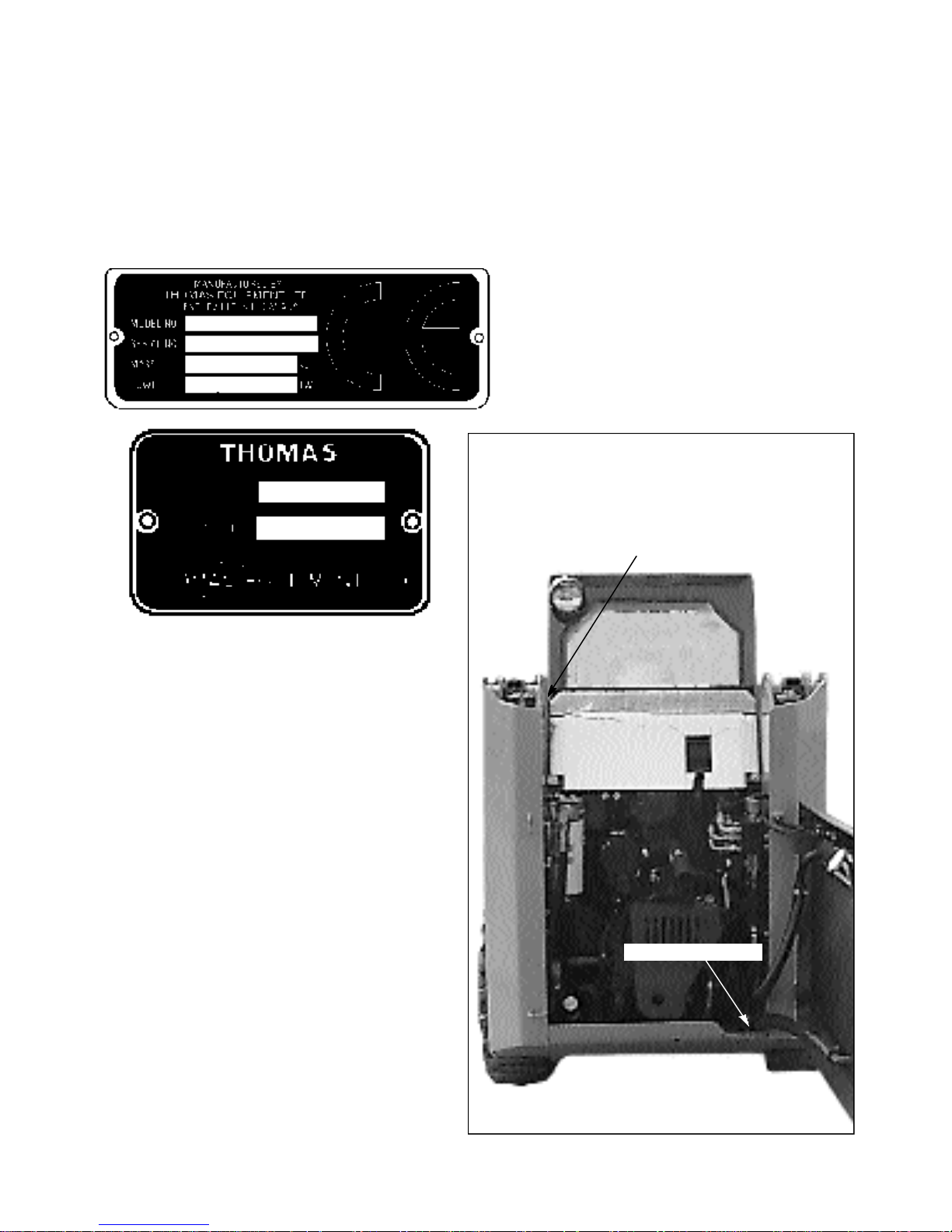
It is important when ordering replacement parts or making a service inquiry to provide both the
model number and serial number of your Thomas loader. The serial number plate is located at the
rear of the machine on the right hand side fuel tank. In the event that the serial number plate is
missing, the model number and serial number are both stamped into the main frame inside the rear
door, next to the hydraulic control valve.
S / N Tag location
S / N Stamp location
C2347
3
Page 4
SAFETY PRECAUTIONS
Practically all Service work involves the need to drive the
loader. The Owner’s / Operator’s Manual, supplied with
each loader, contains safety precautions relating to
driving, operating and servicing that loader. These
precautions are as applicable to the service technicians as
they are to the operator and should be read, understood
and practiced by all personnel.
Prior to undertaking any maintenance, repair, overhaul,
dismantling or re-assembly operations, whether within the
shop facility or “out in the field”, may have an effect
upon safety, not only upon the mechanic carrying out the
work but also upon bystanders.
PERSONAL CONSIDERATIONS
* CLOTHING
The wrong clothing or carelessness in dress can
cause accidents. Check to see that you are
suitably clothed. Some jobs require special
protective equipment.
* SKIN PROTECTION
Used motor oil may cause skin cancer. Follow
work practices that minimize the amount of skin
exposed and length of time used oil stays on
your skin.
* FOOTPROTECTION
Substantial or protective footwear with
reinforced toecaps will protect the feet from
falling objects. Additional oil-resistant
soles will help to avoid spilling.
* SPECIALCLOTHING
For certain work it may be necessary to wear
flame or acid resistant clothing.
CAUTION
Avoid injury through incorrect handling of
components. Make sure your are capable of lifting
the object. If in doubt, get help.
EQUIPMENT CONSIDERATIONS
* MACHINE GUARDS
Before using any machine, check to ensure that
the machine guards are in position and
serviceable. These guards not only prevent parts
of the body or clothing coming in contact with
the moving parts of the machine but also ward
off objects that might fly off the machine and
cause injury.
* EYE PROTECTION
The smallest eye injury may cause loss of vision.
Injury can be avoided by wearing eye protection
when engaged in chiseling, grinding, welding,
painting and any other task that involves foreign
matter.
* BREATHING PROTECTION
Fumes, dust and paint spray are unpleasant and
harmful. These can be avoided by wearing
respiratory protection.
* HEARING PROTECTION
Loud noise may damage your hearing and the
longer the exposure the greater the risks of
hearing damage. Always wear hearing protection
when working around loud machinery.
* HAND PROTECTION
It is advisable to use a protective cream before
work to prevent irritation and skin
contamination. After work, clean your hands
with soap and water. Solvents such as white
spirits, paraffin, etc. may harm the skin.
* LIFTING APPLIANCES
Always ensure that lifting equipment, such as
chains, slings, lifting brackets, hooks and eyes
are thoroughly checked before use. If in doubt,
select stronger equipment. Never stand under a
suspended load or raised implement.
* COMPRESSED AIR
The pressure from a compressed air line is often
as high as 100 PSI (6.9 Bar). Any misuse may
cause injury.
Never use compressed air to blow dust, filing
dirt, etc. away from your work area unless the
correct type of nozzle is fitted.
Compressed air is not a cleaning agent. It will
only move dust etc. from one place to another.
Look around before using an air hose as
bystanders may get grit into their eyes, ears and
skin.
4
Page 5

SAFETY PRECAUTIONS
* HAND TOOLS
Many cuts, abrasions and injuries are caused by
defective tools. Never use the wrong tool for the
job as this leads either to some injury or to a
poor job done.
Never Use:
A hammer with a loose or split handle.
Spanners or wrenches with splayed or worn
jaws.
Wrenches or files as hammers; drills or
clevis pins or bolts as punches.
For removing or replacing hardened pins use a
copper or brass drift rather than a hammer.
For dismantling, overhaul and assembly of major
and sub-components always use the Special
Service Tools recommended. These will reduce
the work effort, labor time and the repair cost.
Always keep tools clean and in good working
order.
* ELECTRICITY
Electricity has become so familiar in day to day
usage that it’s potentially dangerous properties
are often overlooked. Misuse of electrical
equipment can endanger life.
Before using any electrical equipment,
particularly portable appliances, make a visual
check to ensure that the cable is not worn or
frayed and that the plugs, sockets etc. are intact.
Make sure you know where the nearest isolating
switch for your equipment is located.
GENERAL CONSIDERATIONS
* HOUSEKEEPING
Many injuries result from tripping or slipping
over, or on, objects or materials left lying around
by a careless worker.
Prevent these accidents from occurring. If you
notice a hazard, don’t ignore it, remove it.
A clean, hazard free place of work improves the
surroundings and daily environment for
everybody.
* FIRE
Fire has no respect for persons or property. The
destruction that a fire can cause is not always
fully realized. Everyone must be constantly on
guard.
- Extinguish matches, cigars, cigarettes etc.
before throwing them away.
- Work cleanly, disposing of waste material into
proper containers.
- Locate all the fire extinguishers and ensure all
personnel know how to operate them.
- Do not panic, warn those near and sound the
alarm.
- Do not allow or use an open flame near the
loader fuel tank, battery or component parts.
* FIRST AID
In the type of work that mechanics are engaged
in, things such as dirt, grease, fine dust etc. all
settle upon the skin and clothing. If a cut,
abrasion or burn is disregarded it may be found
that a septic condition has formed in a short time.
What appears at first to be trivial could become
painful and injurious. It only takes a few minutes
to have a fresh cut dressed but it will take longer
if you neglect it.
* SOLVENTS
Use only cleaning fluids and solvents that are
known to be safe. Certain types of fluids can
cause damage to components such as seals, etc.
and can cause skin irritation. Solvents should be
checked that they are suitable not only for the
cleaning of components and individual parts but
also that they do not affect the personal safety of
the user.
* CLEANLINESS
Cleanliness of the loader hydraulic system is
essential for optimum performance. When
carrying out service and repairs, plug all hose
ends and components connections to prevent dirt
entry.
Clean the exterior of all components before
carrying out any form of repair. Dirt and abrasive
dust can reduce the efficiency and working life
of a component and lead to costly replacement.
Use of a high pressure washer or steam cleaner is
recommended.
5
Page 6

SAFETY PRECAUTIONS
OPERATIONAL CONSIDERATIONS
* Stop the engine, if at all possible, before
performing any service.
* Place a warning sign on loaders which, due to
service or overhaul, would be dangerous to start.
Disconnect the battery leads if leaving such a
unit unattended.
* Do not attempt to start the engine while standing
beside the loader or attempt to bypass the safety
starting system.
* Avoid prolonged running of the engine in a
closed building or in an area with inadequate
ventilation as exhaust fumes are highly toxic.
* Always turn the radiator cap to the first stop to
allow pressure in the system to dissipate when
the coolant is hot.
* Never work beneath a loader which is on soft
ground. Always take the unit to an area which
has a hard working surface, preferably concrete.
* If it is found necessary to raise the loader for
ease of maintenance, make sure that safe and
stable supports are installed beneath the main
frame before commencing work.
* Use footsteps or working platforms when
servicing those areas of the loader that are not
within easy reach.
* Before loosening any hoses or tubes, switch off
the engine, remove all pressure in the lines by
operating the foot pedals several times. This will
remove the danger of personal injury by oil
pressure.
* If high lift attachments are installed on a loader,
beware of overhead power and telephone lines
when travelling. Drop attachment near to ground
level to increase stability and minimize risks.
* Do not park or attempt to service a loader on an
incline. If unavoidable, take extra care and block
the wheels.
* Escaping hydraulic / diesel fluid under pressure
can penetrate the skin causing serious injury. Do
not use your hand to check for leaks. Use a piece
of cardboard or paper to search for leaks. Stop
the engine and relieve pressure before connecting
or disconnecting lines. Tighten all connections
before starting the engine or pressurizing the
lines. If any fluid is injected into the skin, obtain
medical attention immediately.
* Prior to removing wheels and tires from a loader,
check to determine whether additional ballast
(liquid or weight) has been added. Seek
assistance and use suitable equipment to support
the weight of the wheel assembly.
* When inflating tires beware of over inflation.;
constantly check the pressure. Over inflation can
cause tires to burst and result in personal injury.
* Safety precautions are very seldom the figment
of someone’s imagination. They are the result of
sad experience where most likely someone has
paid dearly through personal injury.
* Heed these precautions and you will protect
yourself accordingly. Disregard them and you
will duplicate the sad experiences of others.
* Prior to pressure testing, make sure all the hoses
and connectors on both the loader and on the test
machine are in good condition and tightly sealed.
Pressure readings must be taken with the gauges
specified. The correct procedure should be
rigidly observed to prevent damage to the system
or the equipment and to eliminate the possibility
of personal injury.
* Always lower equipment to the ground when
leaving the loader.
6
Page 7

SAFETY PRECAUTIONS
SERVICE TECHNIQUES
A. SERVICE SAFETY
Appropriate service methods and proper repair
procedures are essential for the safe, reliable
operation of all motor vehicles as well as the
personal safety of the individual doing the work. This
shop manual provides general directions for
accomplishing service and repair work with
tested effective techniques. Following them will help
assure reliability.There are numerous variations in
procedures, techniques, tools and parts for servicing
vehicles as well as in the skill of the individual doing the
work. This manual cannot possibly anticipate all such
variations and provide advice or cautions as to each.
Accordingly, anyone who departs from the instructions
provided in this manual must first establish that he or she
compromises neither his personal safety nor the vehicle
integrity by his choice of methods, tools or parts.
B. SERVICE TECHNIQUES
Clean the exterior of all components before carrying out
any form of repair. Dirt and abrasive dust can reduce the
efficient working life of a component and lead to costly
replacement.
Use cleaning fluids which are known to be safe. Certain
types of fluid can cause damage to O rings and cause skin
irritation. Solvents should be checked that they are
suitable for the cleaning of components and also that they
do not risk the personal safety of the user.
Time spent on the preparation and cleanliness of working
surfaces will pay dividends in making the job easier and
safer and will result in overhaul components being more
reliable and efficient in operation.
When installing a new hose, loosely connect each end and
make sure the hose takes up the designed position before
tightening the connection. Clamps should be tightened
sufficiently to hold the hose without crushing and to
prevent chafing.
The hoses are the arteries of the unit; be sure they are in
good condition when carrying out repairs or maintenance
otherwise the machines output and productivity will be
affected.
After hose replacement to a moving component, check
that the hose does not foul by moving the component
through the complete range of travel.
Hose connections which are damaged, dented , crushed or
leaking, restrict oil flow and the productivity of the
components being served. Connectors which show signs
of movement from the original swaged position have
failed and will ultimately separate completely.
A hose with a chafed outer cover will allow water entry.
Concealed corrosion of the wire reinforcement will
subsequently occur along the hose length with resultant
hose failure.
Ballooning of the hose indicates an internal leakage due
to structural failure. This condition rapidly deteriorates
and total hose failure soon occurs.
Kinked, crushed, stretched or deformed hoses generally
suffer internal structural damage which results in oil
restriction, a reduction in the speed of operation and
ultimate hose failure.
Free moving, unsupported hoses must never be allowed to
touch each other or related working surfaces. This causes
chafing which reduces hose life.
Replace O rings, seals or gaskets whenever they are
disturbed. Never mix new and old seals and O rings,
regardless of condition. Always lubricate new seals and O
rings with hydraulic oil before installation.
When replacing component parts use the correct tool for
the job.
C. HOSES AND TUBES
Always replace hoses and tubes if the end connections are
damaged. Be sure any hose installed is not kinked or
twisted.
D. PRESSURE TESTING
Prior to pressure testing, be sure all hoses are in good
condition and all connections tight. Pressure readings
must be taken with gauges of specified pressure readings.
The correct procedure should be rigidly observed to
prevent damage to the system or the equipment and to
eliminate the possibility of personal injury.
7
Page 8
SAFETY PRECAUTIONS
E. BEARINGS
Bearings which are considered suitable for further service
should be cleaned in a suitable solvent and immersed in
clean lubricating oil until required.
Installation of a bearing can be classified into two (2)
ways:
press fit on rotating parts such as shafts and gears,
push fit into static locations such as reduction gear
houses.
Where possible, always install the bearing onto the
rotating components first. Use the correct tools or a press
to install a bearing or bushing. In the absence of the
correct tools or press, heat the bearing and / or casing in
hot oil to assist the installation of the bearing.
When bearings or bushings are removed, always carefully
check that the bearing is free from discoloration and signs
of overheating. Also check for mechanical damage such
as excessive clearance, nicks and scuffing. If in doubt,
replace the bearings or bushings.
C729
Bearings should never be removed unless absolutely
necessary. Always use the recommended puller to reduce
the risk of bearing or related component failure.
These bearings and bushings are subjected, in normal
operation, to high working loads and adverse conditions.
Be sure during normal routine servicing, maintenance or
repair that bearings are given the right attention and are
installed with care.
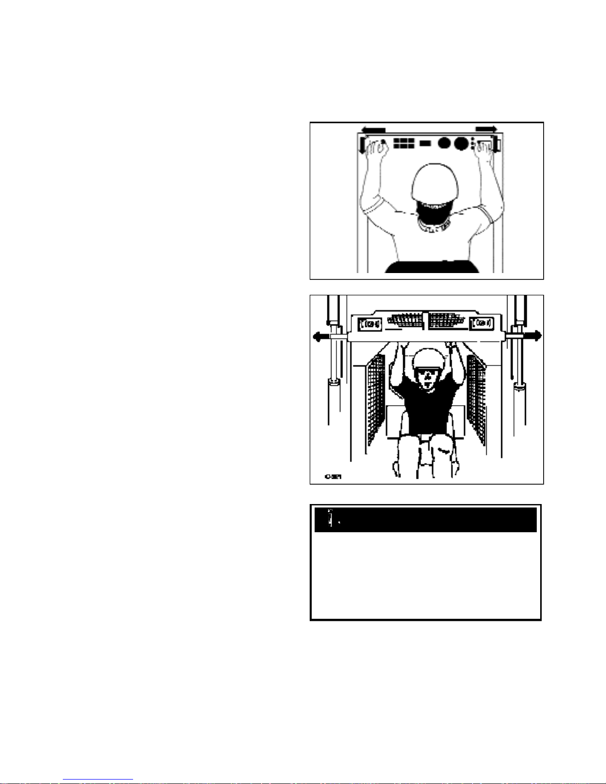
F. BOOM SUPPORTS
For safety while performing regular service or
maintenance work, the loader is equipped with boom
supports.
The boom supports, when extended, prevent the boom
arms from dropping if hydraulic pressure is relieved or
the foot control pedals are accidentally cycled.
To operate the boom supports, first remove any bucket or
attachment from the quick - tach; raise the boom arms to
full height and shut off the engine. Raise the boom
handles up and push out toward the boom arms to extend
the boom supports. (fig. C729, C321)
WARNING
To avoid personal injury, service the loader with the
boom arms down and the bucket or attachment
lowered to the ground. If it is necessary to service the
loader with the boom arms raised, be sure to engage
the boom supports. Never work under or around a
loader with raised boom arms without the boom
supports engaged.
8
Page 9

THOMAS
9
Page 10

TABLE OF CONTENTS
Section 1 Hydraulic System
Hydraulic Circuit...............................................................................1.1
Gear Pump .........................................................................................1.2
Control Valve.....................................................................................1.3
Hydraulic Cylinders...........................................................................1.4
Oil Filter .............................................................................................1.5
Oil Cooler..........................................................................................1.6
Oil Reservoir......................................................................................1.7
Trouble Shooting ...............................................................................1.8
Torque Chart ......................................................................................1.9
Section 2 Hydrostatic Drive System
Hydrostatic Drive Circuit..................................................................2.1
Specifications.....................................................................................2.2
General Information...........................................................................2.3
Trouble Shooting ...............................................................................2.4
Pressure Tests.....................................................................................2.5
Towing Procedure ..............................................................................2.6
Flushing The Hydraulic System ........................................................2.7
Start - up Procedure ...........................................................................2.8
Gear Pump Replacement...................................................................2.9
Tandem Pump Replacement ..............................................................2.10
Tandem Pump Parts Diagram............................................................2.11
Drive Motor .......................................................................................2.12
Section 3 Final Drive
Specifications and Maintenance ........................................................3.1
Lubrication .........................................................................................3.2
Drive Chain........................................................................................3.3
Drive Motor Sprocket........................................................................3.4
Axle Assembly...................................................................................3.5
Trouble Shooting ...............................................................................3.6
Section 4 Controls
Steering..............................................................................................4.1
Foot Pedals.........................................................................................4.2
Hand Controls ....................................................................................4.3
Throttle...............................................................................................4.4
Restraint Bar......................................................................................4.5
Parking Brake ....................................................................................4.6
Trouble Shooting ...............................................................................4.7
10
Page 11

TABLE OF CONTENTS
Section 5 Electrical
General Information...........................................................................5.1
Wiring Schematics.............................................................................5.2
Instrumentation..................................................................................5.3
Ignition Switch...................................................................................5.4
Engine Glow Plugs ............................................................................5.5
Battery................................................................................................5.6
Electrical Panel..................................................................................5.7
Starter Circuit.....................................................................................5.8
Charging Circuit ................................................................................5.9
Safety Circuit .....................................................................................5.10
Cooling Fan Circuit ..........................................................................5.11
Auxiliary Circuit ................................................................................5.12
Accessory Circuit...............................................................................5.13
Trouble Shooting ...............................................................................5.14
Section 6 Main Frame
Quick - Tach .......................................................................................6.1
Boom Arms........................................................................................6.2
Boom Support....................................................................................6.3
ROPS .................................................................................................6.4
Rear Door...........................................................................................6.5
Section 7 Engine
Maintenance .......................................................................................7.1
Cylinder Head ....................................................................................7.2
Replacement.......................................................................................7.3
Specifications.....................................................................................7.4
Trouble Shooting ...............................................................................7.5
Section 8 Maintenance & Specifications
Maintenance .......................................................................................8.1
Trouble Shooting ...............................................................................8.2
Special Tools ......................................................................................8.3
Specifications.....................................................................................8.4
Conversion Charts..............................................................................8.5
11
Page 12

THOMAS
12
Page 13

SECTION 1 HYDRAULIC SYSTEM
1
Hydraulic Circuit 1.1
Schematic . . . . . . . . . . . . . . . . . . . . . . . . . . . . . . . . . . . . . . . . . . . . . . . . . . . . . . . . . pg. 1-2
Specifications . . . . . . . . . . . . . . . . . . . . . . . . . . . . . . . . . . . . . . . . . . . . . . . . . . . . . . pg. 1-3
Maintenance Schedule . . . . . . . . . . . . . . . . . . . . . . . . . . . . . . . . . . . . . . . . . . . . . . . pg. 1-3
General Information . . . . . . . . . . . . . . . . . . . . . . . . . . . . . . . . . . . . . . . . . . . . . . pg. 1-4 ~ 5
Gear Pump 1.2
Replacing the Gear Pump . . . . . . . . . . . . . . . . . . . . . . . . . . . . . . . . . . . . . . . . . . . . pg. 1-6
Start - up Procedure . . . . . . . . . . . . . . . . . . . . . . . . . . . . . . . . . . . . . . . . . . . . . . . . . pg. 1-7
Testing (See control valve relief) . . . . . . . . . . . . . . . . . . . . . . . . . . . . . . . . . . pg. 1-14 ~ 15
Control Valve 1.3
Testing / Adjusting the Relief Valve . . . . . . . . . . . . . . . . . . . . . . . . . . . . . . . . . . . . pg. 1-8
Control Valve Removal . . . . . . . . . . . . . . . . . . . . . . . . . . . . . . . . . . . . . . . . . . . . . . pg. 1-9
Control Valve Installation . . . . . . . . . . . . . . . . . . . . . . . . . . . . . . . . . . . . . . . . . . . .pg. 1-10
Exploded Illustration (to S / N LC001080) . . . . . . . . . . . . . . . . . . . . . . . . . . pg. 1-12 ~ 13
Exploded Illustration (S / N LC001081 onward) . . . . . . . . . . . . . . . . . . . . . . . . . pg. 1-15
Control Valve Disassembly / Repair . . . . . . . . . . . . . . . . . . . . . . . . . . . . . . . pg. 1-16 ~ 25
Hydraulic Cylinders 1.4
General Information . . . . . . . . . . . . . . . . . . . . . . . . . . . . . . . . . . . . . . . . . . . . . . . . pg. 1-26
Testing Piston Seals . . . . . . . . . . . . . . . . . . . . . . . . . . . . . . . . . . . . . . . . . . . . . . . . pg. 1-27
Lift Cylinder Replacement . . . . . . . . . . . . . . . . . . . . . . . . . . . . . . . . . . . . . . . . . . . pg. 1-28
Tilt Cylinder Replacement . . . . . . . . . . . . . . . . . . . . . . . . . . . . . . . . . . . . . . . . . . . pg. 1-29
Cylinder Disassembly . . . . . . . . . . . . . . . . . . . . . . . . . . . . . . . . . . . . . . . . . . pg. 1-30 ~ 31
Cylinder Inspection . . . . . . . . . . . . . . . . . . . . . . . . . . . . . . . . . . . . . . . . . . . . . . . . pg. 1-32
Cylinder Assembly . . . . . . . . . . . . . . . . . . . . . . . . . . . . . . . . . . . . . . . . . . . . . pg. 1-32 ~ 33
Hydraulic Oil Filter 1.5
General Information . . . . . . . . . . . . . . . . . . . . . . . . . . . . . . . . . . . . . . . . . . . . . . . . pg. 1-34
Filter Replacement . . . . . . . . . . . . . . . . . . . . . . . . . . . . . . . . . . . . . . . . . . . . . . . . . pg. 1-34
Hydraulic Oil Cooler 1.6
General Information . . . . . . . . . . . . . . . . . . . . . . . . . . . . . . . . . . . . . . . . . . . . . . . . pg. 1-35
Oil Cooler Replacement . . . . . . . . . . . . . . . . . . . . . . . . . . . . . . . . . . . . . . . . . . . . . pg. 1-35
Hydraulic Oil Reservoir 1.7
General Information . . . . . . . . . . . . . . . . . . . . . . . . . . . . . . . . . . . . . . . . . . . . . . . . pg. 1-36
Checking the Oil Level . . . . . . . . . . . . . . . . . . . . . . . . . . . . . . . . . . . . . . . . . . . . . pg. 1-36
Adding Oil . . . . . . . . . . . . . . . . . . . . . . . . . . . . . . . . . . . . . . . . . . . . . . . . . . . . . . . pg. 1-36
Servicing the Reservoir . . . . . . . . . . . . . . . . . . . . . . . . . . . . . . . . . . . . . . . . . . . . . pg. 1-37
Trouble Shooting 1.8
Trouble Shooting Chart . . . . . . . . . . . . . . . . . . . . . . . . . . . . . . . . . . . . . . . . . pg. 1-38 ~ 39
Torque Chart 1.9
Hydraulic Hose and Fitting Torque Chart . . . . . . . . . . . . . . . . . . . . . . . . . . . . . . . pg. 1-39
1-1
Page 14
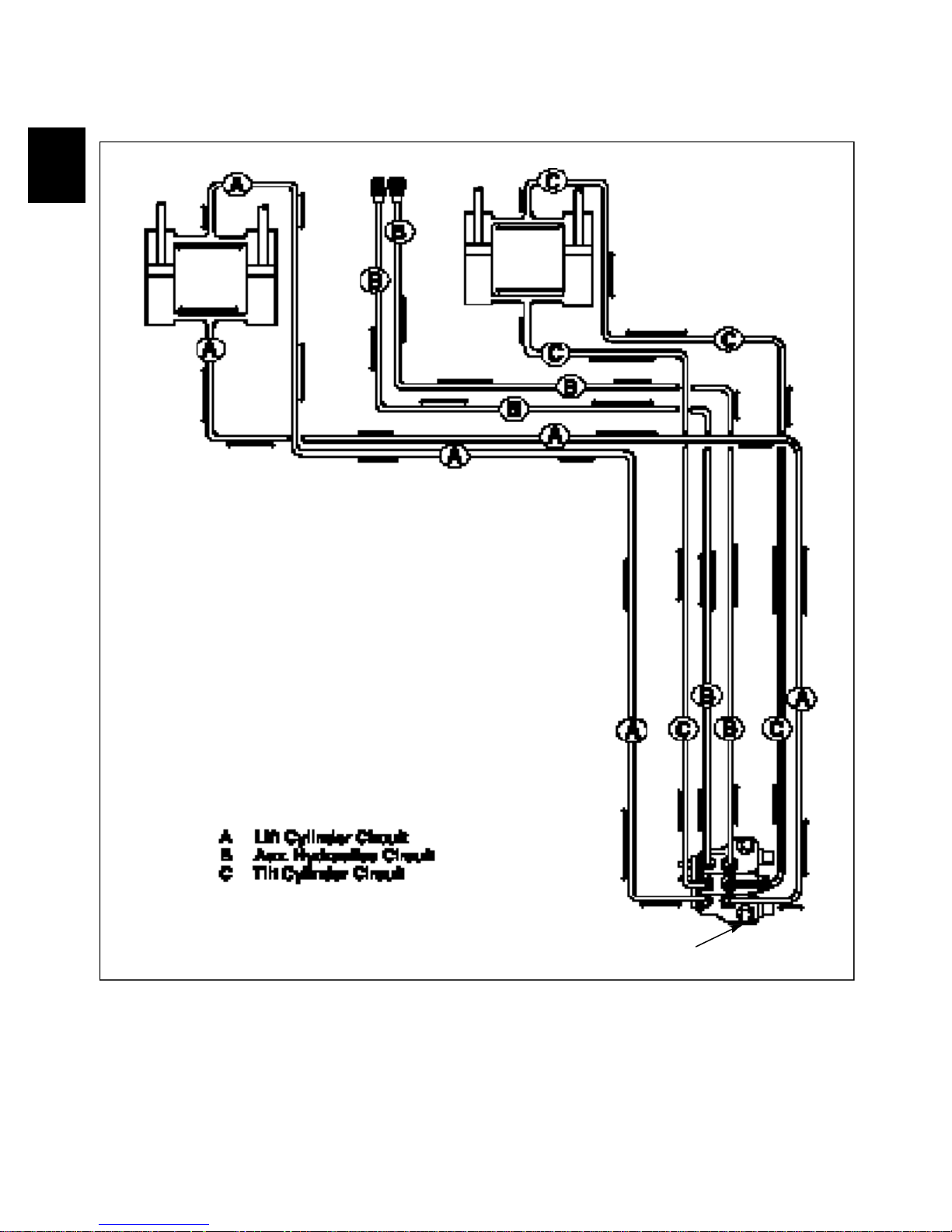
HYDRAULIC CIRCUIT 1.1
Lift Cylinders Tilt CylindersAuxiliary Couplers
C1008
NOTE: Foot pedal control operated machine illustrated. Hydraulic fluid comes out the port closest to the spool
1-2
Control Valve Outlet
end of the valve when the spool is pushed in.
Hydraulic fluid received at the fixed end of the cylinder
pushes it out. When the hydraulic cylinder receives fluid
at the ram (rod) end, it retracts.
Page 15

SPECIFICATIONS & MAINTENANCE 1.1
1
Hydraulic Specifications
Pump Type . . . . . . . . . . . . . . . . . . . . . . . . . . . . . . . . . . . Gear, 0.61 cu. in. (11cc)
Pump Brand . . . . . . . . . . . . . . . . . . . . . . . . . . . . . . . . . . . . . . . Sauer Sundstrand
Pump Capacity (theoretical) . . . . . . . . . . . . . . . . . . . . . . . . . 8.7 GPM (33 LPM)
Rated Speed . . . . . . . . . . . . . . . . . . . . . . . . . . . . . . . . . . . . . . . . . . . . 3000 RPM
Control Valve . . . . . . . . . . . . . . . . . . . . . . . . . . . . . . . . . . . . . . . . . Parallel Type
Main Relief Pressure, +/- 50PSI (3.5 Bar) . . 2150 PSI (148 Bar) @ Zero Flow
Reservoir Capacity . . . . . . . . . . . . . . . . . . . . . . . . . . . . . . . . . . . 34 L (9 gallons)
Fluid Type . . . . . . . . . . . . . . . . . . . . . . . . . . . . . . . . . . . 10W30 API SE / CD Oil
Reservoir Filtration . . . . . . . . . . . . . . . . . . . . . . . . . . . . . . . . . . . . . . 100 Micron
System Filtration . . . . . . . . . . . . . . . . . . . . . . . . . . . . . . . . . . . . . . . . . . 5 Micron
Lift Cylinders . . . . . . . . . . . . . . . . . . . . . . . . . . . . . . . . . . . (2) 2’’ Bore Diameter
Lift Cylinder Rods . . . . . . . . . . . . . . . . . . . . . . . . . . . . . . . . . . 1.125’’ Diameter
Tilt Cylinders . . . . . . . . . . . . . . . . . . . . . . . . . . . . . . . . . . . (2) 2’’ Bore Diameter
Tilt Cylinder Rods . . . . . . . . . . . . . . . . . . . . . . . . . . . . . . . . . . . 1.125’’ Diameter
Lift Cycle + / - 1.5 seconds (Up / Down) . . . . . . . . . . . . . . . . . . . . . . 5.4 / 3.54
Tilt Cycle + / - 1.5 seconds (Up / Down) . . . . . . . . . . . . . . . . . . . . . 2.35 / 3.06
Allowable Drop, Measured at the Cylinder Rod, Engine Off,
@ Rated Capacity and Operating Temperature . . . . . . 1.5’’ (38mm) / 3 Minutes
Maintenance Schedule . . . . . . . . . First (HRS) . . . . Every (HRS)
Oil level check . . . . . . . . . . . . . . . . . . . . . . . . . 8 . . . . . . . . . . . . . . . . . . 8
Oil filter change . . . . . . . . . . . . . . . . . . . . . . . . 50 . . . . . . . . . . . . . . . . . 150
General system check (leaks etc.) . . . . . . . . . . 8 . . . . . . . . . . . . . . . . . . 8
Lubricate (grease pivots) . . . . . . . . . . . . . . . . . 8 . . . . . . . . . . . . . . . . . . 8
Reservoir filter change . . . . . . . . . . . . . . . . . 1000 . . . . . . . . . . . . . . . 1000
Hydraulic oil change . . . . . . . . . . . . . . . . . . . 1000 . . . . . . . . . . . . . . . 1000
1-3
Page 16
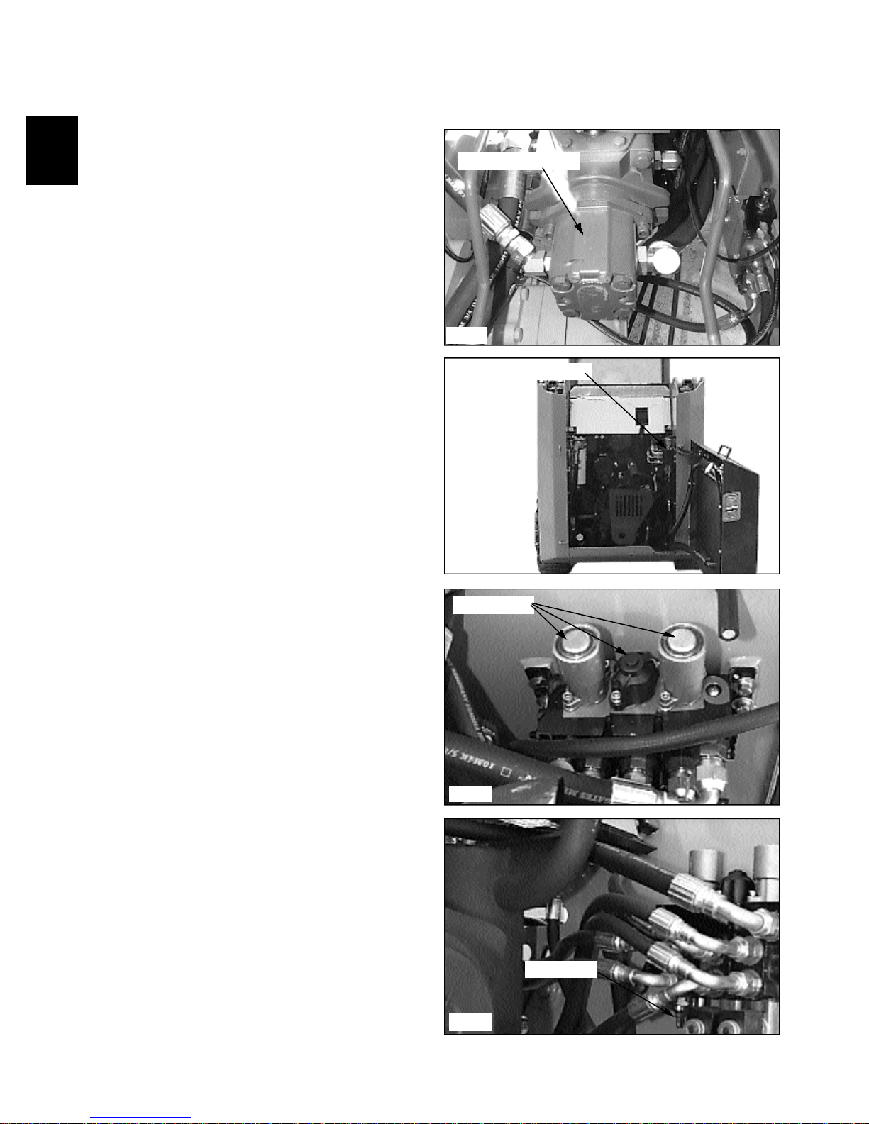
GENERAL INFORMATION 1.1
Hydraulic System
Oil is drawn from the hydraulic oil reservoir through a
100 micron element. From there it travels to the main
hydraulic pump. (fig. C2353).
The hydraulic pump is a gear type which is driven by a
shaft and coupler through the hydrostatic drive pump at
engine speed. The oil then flows from the gear pump to
the hydraulic control valve. (fig. C2347).
Gear pump location
The hydraulic control valve is equipped with an
adjustable relief valve which is adjusted to 2150 PSI (148
Bar). The control valve is a parallel type with 3 spools
(banks). The various spools activate the boom, bucket and
auxiliary hydraulic functions.
When the spools are in neutral, oil flows from the
hydraulic gear pump, through the control valve and
returns to the 10 micron hydraulic filter. From the
hydraulic filter, the fluid flows to charge the tandem
hydrostatic pump and pressurize the hydraulic brake
release system and then back to the hydraulic reservoir.
Each control valve section spool end contains a centering
spring which returns the spool to neutral when the foot
pedal, or control handle, is released. (fig. C2350).
The boom section, on foot control operated loaders, has a
detent mechanism to hold the spool in the float position.
The auxiliary section is operated by foot pedal operation,
or may have an optional electrical solenoid operated
control, and may be engaged momentarily by the control
lever mounted switch, forward or reverse, or by engaging
the dash mounted toggle switch for constant power in the
forward direction only.
C2353
Control valve location
C2347
Spring return
The system relief valve operates whenever a hydraulic
function has been restricted or over loaded. (fig. C2248).
To protect against excessive pressure build up, the relief
valve opens and allows oil to return to the return outlet.
The system relief valve is adjustable, and is preset at
2150 PSI. (148 Bar)
1-4
C2350
Relief valve
C2348
Page 17

GENERAL INFORMATION 1.1
1
THOMAS
1-5
Page 18
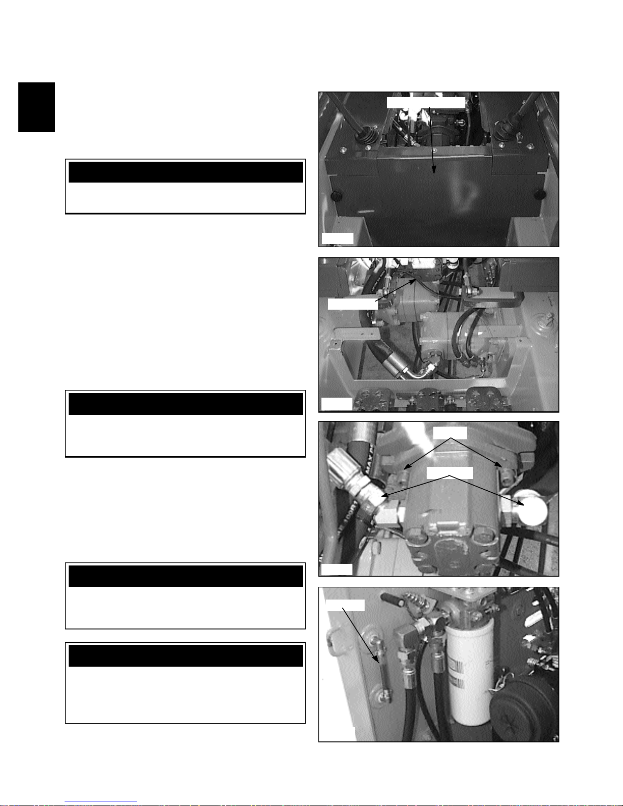
GEAR PUMP 1.2
Replacement
Start the gear pump removal procedure by removing any
attachment, raising the boom arms and engaging the
boom support pins. Shut off the engine.
WARNING
To prevent personal injury, never work under the
boom arms without the boom supports engaged.
1 Remove the seat and hydrostatic shield. (fig. C2358,
C2360)
2 Attach a vacuum system to the hydraulic oil reservoir
filler location. Or drain the oil reservoir. Seal the threads
on the drain plug, if removed, with teflon tape or a liquid
form of pipe sealant before installing.
3 Disconnect the hydraulic hoses from the gear pump.
(fig. C2353) Remove the pump fittings. Cap all open
hoses to prevent contamination. After capping ends you
may unhook vacuum system from oil reservoir.
4 Remove the 2 bolts holding the gear pump to the
hydrostatic tandem section. (fig. C2353) Remove the gear
pump. Check the seal. Replace if required.
Hydrostatic shield
C2358
Gear pump
IMPORTANT
If gear pump replacement is being done because of
failure, the hydraulic system and oil should be
checked for contamination. See section 2.7.
5 Replace gear pump in reverse order.
6 Start the engine and check for leaks. Do not use your
hands to find leaks.
7 Check the fluid level in the hydraulic oil reservoir
and replenish as required. (fig. C2354)
8 Follow the Start Up Procedure upon completing
repairs. See next page.
WARNING
Use caution when dealing with fluid under pressure.
Escaping fluid under pressure can penetrate the skin
and cause serious injury.
IMPORTANT
When making repairs to the hydraulic system, keep
the work area and parts clean. Use caps and plugs on
all open lines and ports. Follow the torque chart
when tightening lines and fittings.
C2360
Screws
Hyd. lines
C2353
Oil level
1-6
C2354
Page 19

GEAR PUMP 1.2
1
Start up Procedure
1 Mount the gear pump to the loader. (fig. C2353)
2 Connect the hydraulic lines. Torque fittings and lines
according to the torque chart section 1.8.
3 Start the pump and run for 3 minutes each @
a. Half speed at zero flow
b. Half speed, intermittently loaded to 500 psi (35
bar)
c. Full speed, intermittently loaded to 1000 psi (69
bar)
4 Check for leaks.
5 Check flow and pressure at rated speed as outlined in
section 1.3.
WARNING
Use caution when dealing with fluid under
pressure. Escaping fluid under pressure can
penetrate the skin and cause serious injury. Never
use your hands to check for system leaks.
Screws
Hyd. lines
C2353
Intermittently load the gear pump at start up
IMPORTANT
Be sure the hydraulic oil reservoir is at the proper
level before performing test.
Flow test meter p / n 960456
C2352
1-7
Page 20
CONTROL VALVE 1.3
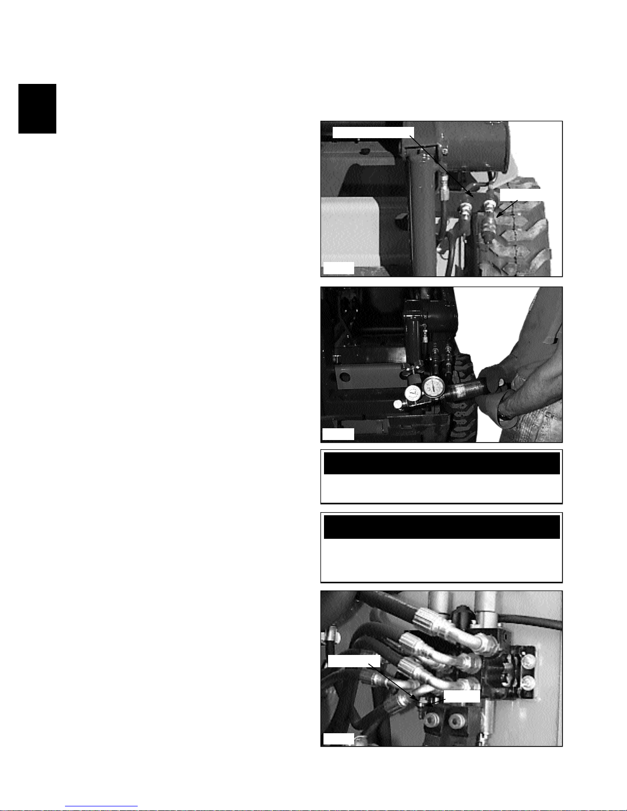
Testing and Adjusting the Relief Valve Pressure
NOTE: This test also checks the status of the gear
pump capacities.
Hoses and gauges required for this test must be capable
of withstanding 3000 PSI (207 Bar) continuous pressure,
and hydraulic flow meter capable of measuring 30 gallons
per minute. (113 LPM)
1 The female coupler attached to the loader provides
the power out when the auxiliary control is engaged. (fig.
C2351) Connect the flow meter and pressure gauge inlet
side to match the power out of the female auxiliary
coupler to prevent meter and gauge damage. Be sure to
connect a return line to the male auxiliary hydraulic quick
coupler. Install the flow meter / pressure tester to the
auxiliary hydraulic quick couplers. (fig. C2352)
2 Start the engine and engage the auxiliary hydraulic
system. Increase the engine speed to full operating RPM.
(See Section 7 for checking and adjusting engine speed to
3000 RPM plus or minus 25 RPM)
3 Turn the flow control valve on the flow meter to
restrict the oil flow down to 2 GPM. (7.5 LPM) As you
are turning the flow control valve, watch the pressure
gauge and make sure it does not go over 3000 PSI.(207
Bar) Stop further adjustment immediately if the reading
goes over this setting. Shut off the auxiliary hydraulic
system and shut off the engine. Move to step 6 to make
initial setting.
4 Repeat steps 2 and 3 if necessary. Allow the loader to
operate at this setting until the oil temperature has
increased to 160° F (71ºC), operating temperature.
5 Turn the flow control valve further to restrict the oil
flow to no flow. (Zero) Correct pressure setting is 2150
PSI +/- 100 PSI. (148 Bar, +/-6.9 Bar)
6 If adjustment is necessary, shut down the auxiliary
hydraulic system, shut off the engine and return the flow
control valve to the open position. Locate the control
valve in the engine compartment.
7 Loosen the jam nut on the relief valve adjusting
screw and turn the screw clockwise, counting the turns,
until the screw bottoms out. (fig. C2348)
8 Turn the screw back out lesser turns than you turned
in to increase pressure, or out more turns to decrease
pressure.
9 Retake the pressure readings by performing steps 2
through 5. If necessary make further adjustments by
repeating steps 6 through 9.
NOTE: If inadequate pressure and / or flow is not
available, the gear pump could be failing or the inlet
to the gear pump is restricted.
Auxiliary couplers
Pressure out
C2351
C2352
CAUTION
Adjusting the relief valve setting too high may cause
damage to the gear pump.
WARNING
To prevent personal injury or damage to the loader,
do not adjust the relief valve while the engine is
operating.
Relief valve
Jam nut
C2348
1-8
Page 21

CONTROL VALVE 1.3
1
Control Valve Removal
1 Remove any attachment, lower the boom arms,
engage the parking brake and shut off the engine
IMPORTANT
Clean the work area prior to repair. Cap all open
lines, fittings and ports to prevent contamination.
C2348
Solenoid coil
mounting nuts
2 Disconnect the spool locks solenoid, and electrical
auxiliary solenoid wiring connectors if equipped. (fig.
C2348, C2349)
3 Disconnect the control cables. (fig. C2367)
4 Disconnect the return line from the control valve and
remove the adapter fitting. Plug and cap all open ports
and hose ends.
5 Disconnect the 6 hoses going to the boom, bucket
and auxiliary circuits. Marking the hoses as you remove
them is recommended for safety and to ease re-assembly
and assure the circuits are functioning properly at restart.
6 Disconnect the the inlet hose coming from the gear
pump. Cap the hose and fitting and remove the adapter
fitting in the control valve.
Solenoid coil
Return
line
C2349
Disconnect control cables
C2367
7 Remove the 4 bolts holding the control valve to the
mount and remove the control valve. (fig. C2350)
Control valve mounts
C2350
1-9
Page 22

CONTROL VALVE 1.3
Control Valve Installation
When installing a new control valve, always inspect the
exterior for shipping or other damage, such as bent
brackets, broken spring return caps or damaged spool
lock mechanism. Repair all damaged parts before
installation to the loader.
1 Mount the control valve to the loader. (fig. C2324a)
IMPORTANT
Follow the hydraulic fitting torque chart in Section
1.10 when connecting fittings and lines.
2 Connect the control cables to the spools.
3 Connect the various hydraulic lines to their proper
ports. (fig. C2324b).
Install valve to mount
C2324a
Control valve fittings
WARNING
Use extreme caution when checking the hydraulic
system for leaks. Fluid under pressure can penetrate
the skin and cause serious injury.
4 Connect the solenoid coils to the control valve locks.
Apply a drop of Loctite 242 (blue) to the knurled
retaining nut.
WARNING
All safety switches must be connected and
functioning to prevent possible operator injury.
5 Verify fluid level in th hydraulic oil reservoir. (fig.
C2354). Top off as required to bring oil level to
approximately half way in the site gauge.
WARNING
Verify the relief valve pressure setting after replacing
or servicing the control valve.
C2423b
Check fluid level
C2354
Replenish fluid as required
1-10
C2355
Page 23

1
THOMAS
1-11
Page 24
CONTROL VALVE 1.3
35
9
30
29
1
34
33
32
31
2
36
7
3
4
5
6
7
Salami Model to S / N LC001080
8
9
23
6
10
11
28
27
26
22
4
25
20
7
21
24
12
13
12
14
15
16
17
18
19
C1079
1-12
Page 25

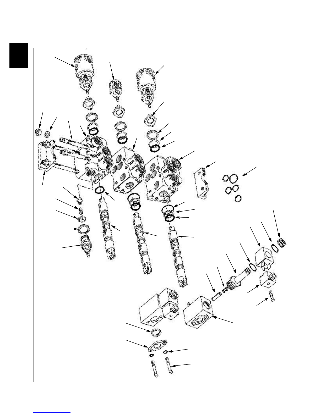
CONTROL VALVE 1.3a
1
Diagram C1079 Legend
1 Auxiliary spool spring return
2 Tilt spool spring return
3 Lift spool spring return
4 Plate
5 Washer
6 Seal shim
7 Seal
8 Outlet / lift section body
9 Mounting bracket
10 Section seals
11 Knurled nut
12 Seal
13 Solenoid coil
14 Spool lock solenoid post
15 Spring
16 Lock pin
17 Electrical connector
18 Screw
19 Spool lock body
20 Lock washer
21 Screw
22 Scraper seal
23 Seal
24 Lift spool
25 Tilt spool
26 Auxiliary spool
27 Relief valve body
28 Washer seal
29 Spring washer
30 Spring
31 Poppet valve
32 Inlet / auxiliary section body
33 Tie bolt
34 Flat washer
35 Nut
36 Tilt section body
1-13
Page 26
CONTROL VALVE 1.3
Disassembly / Repair
Remove the hydraulic control valve as outlined in the
removal section, page 1-7. Ensure all openings are
plugged to prevent solvents and dirt from contaminating
the control valve assembly. Before disassembling the
hydraulic control valve, clean the body with a suitable
solvent and dry with compressed air.
WARNING
To avoid eye injury, use safety goggles when clean ing with compressed air.
Refer to diagram C1079, pg. 1-11, to assist in the
disassembly of the control valve.
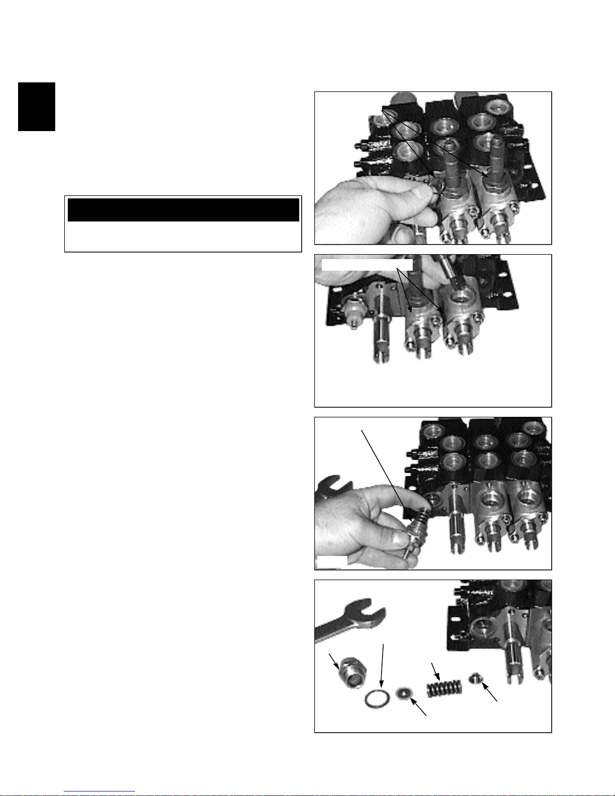
1 Remove the solenoid coils and O-ring seals. (fig.
C2368).
2 Remove the locking pin assembly from the adapter
block. (fig. C2369)
3 Remove the pressure relief valve. (fig. C2370) Tip
the valve down slightly to ensure the valve poppet comes
out with the spring.
O-ring seals
C2368
Locking pin assembly
C2369
Note: Figure C2371 shows an exploded view of the
relief valve system.
Relief valve assembly
C2370
Sealing washer
Cap
C2371
Spring
Valve poppet
Spring washer
1-14
Page 27
CONTROL VALVE 1.3
1
Disassembly / Repair (cont’d)
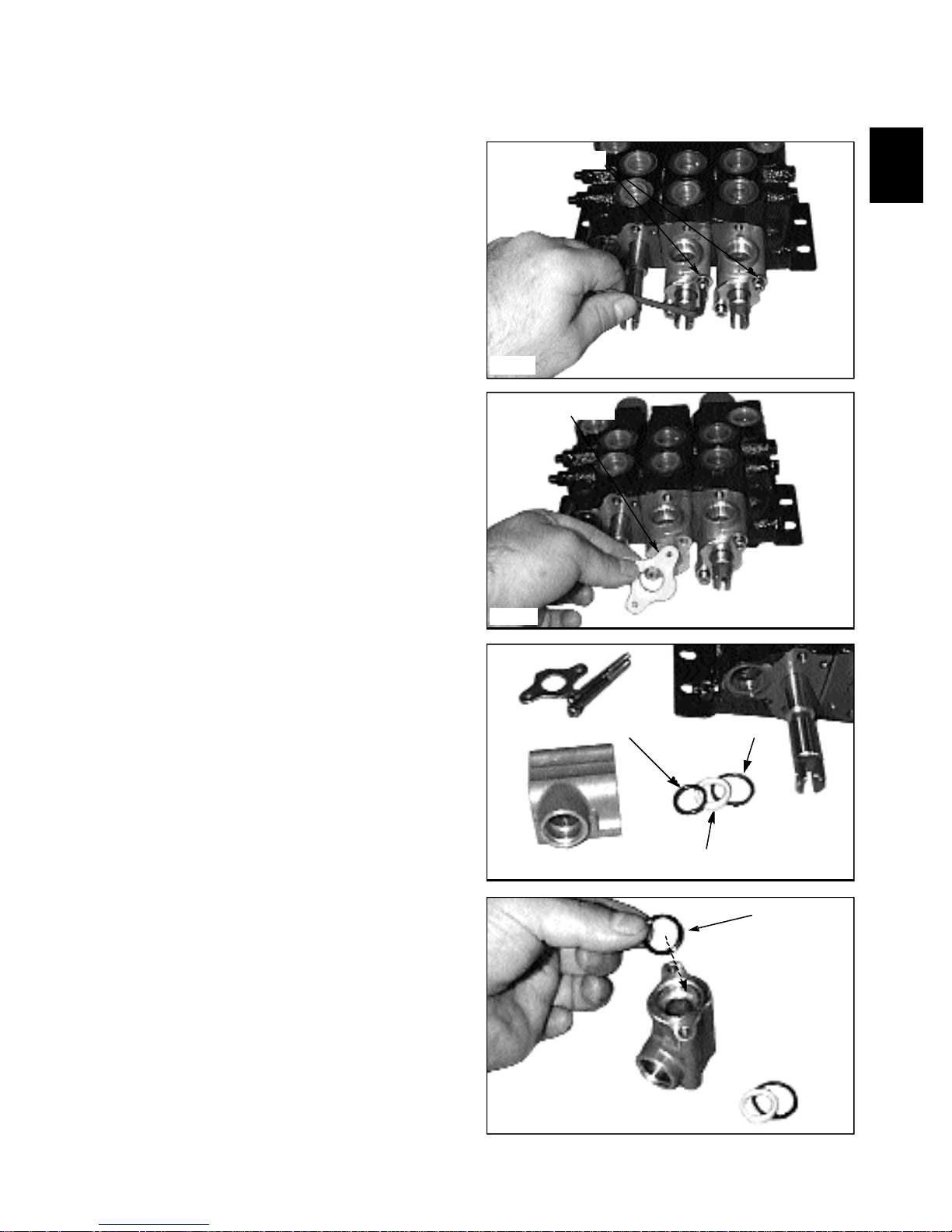
4 Remove the screws retaining the lock adapters to the
control valve assembly. (fig. C2372).
5 Remove the plate and adapter from the control valve
and spool. (fig. C2373, C2374)
Remove screws
C2372
Scraper seal plate
6 Remove the O-ring seals and seal shim. (fig. C2374).
Discard the seals and replace with new.
7 Clean the lock adapter with solvent and inspect the
inside of the lock adapter for excessive wear such as
gouging or chipping. Replace with new if worn.
8 Lubricate a new spool O-ring with system oil and
install to the lock adapter. (fig. C2375)
C2373
C2374
Spool O-ring
Section O-ring
O-ring shim
Spool O-ring
C2375
1-15
Page 28
CONTROL VALVE 1.3
Disassembly / Repair (cont’d)
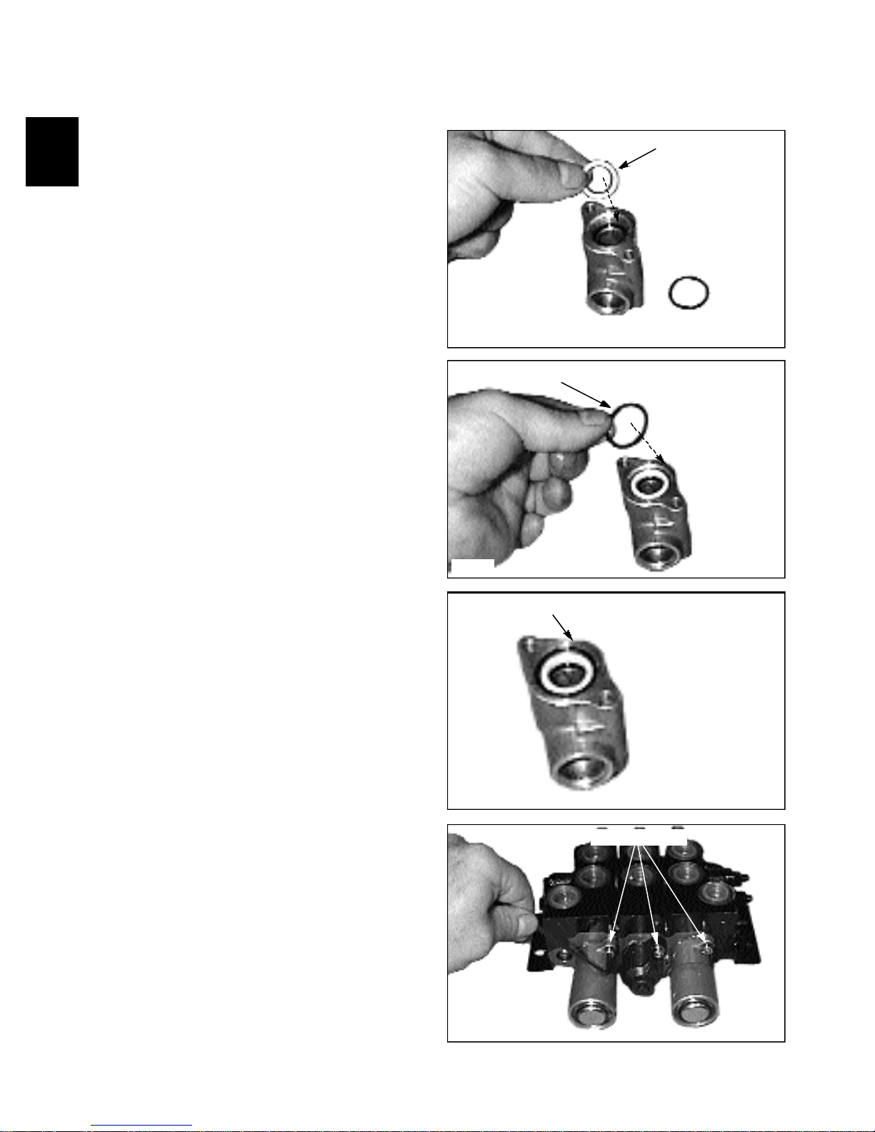
9 Lubricate the spool O-ring shim with system oil and
install over spool seal. (fig. C2376).
10 Lubricate the section O-ring seal with system oil and
install to the lock adapter assembly. (fig. C2377).
Spool O-ring shim
C2376
Section O-ring seal
11 Figure C2378 shows the completely resealed lock
adapter assembly ready to be installed to the control valve
assembly.
12 Remove the screws retaining the spring return caps to
the control valve assembly. (fig. C2379). Remove the
spring return assemblies.
C2377
Lock adapter assembly
C2378
Remove screws
1-16
C2379
Page 29
CONTROL VALVE 1.3
1
Disassembly Repair (cont’d)
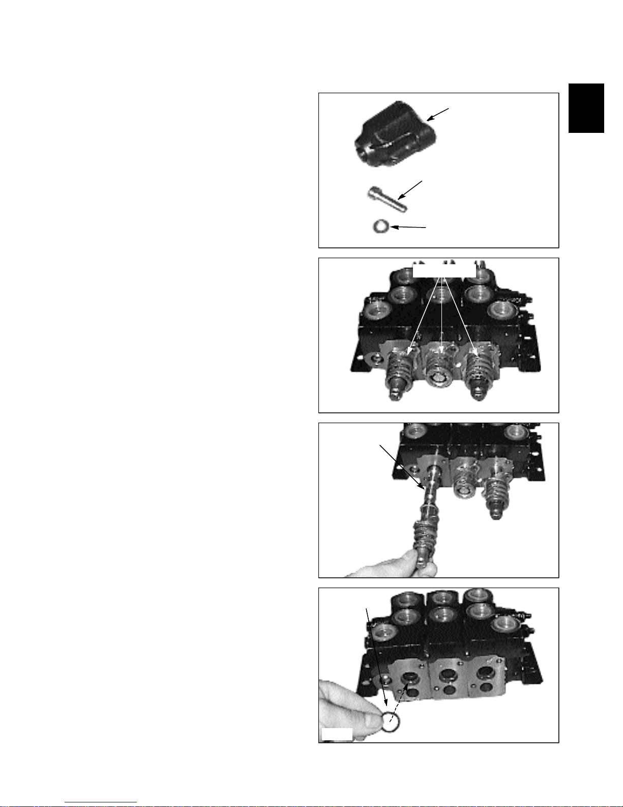
13 Note: The plastic cap over the tilt spring has flat
washers to distribute the load of the mounting screws to
prevent cap damage. (fig. C2380). Be sure to install the
flat washers when reassembling to the control valve.
14 Figure C2381 shows spring assemblies and detent
mechanisms as viewed with the caps removed.
Tilt spring return cap
Mounting screws
Flat washers
C2380
Return springs
15 Remove the section spools noting their location to
the appropriate bores. (fig. C2382). Do not replace the
spools in any other spool bores than the one it came out
of. Clean the spools and valve sections with solvent and
inspect for gouging or chipping. Replace sections as
required. Minor scratches on the spool may be removed
with fine emery cloth. Be sure to remove all solvent from
the control valve body if no further disassembling of the
control valve is to be performed.
16 Install new O-ring seals at time of assembly. (fig.
C2383) Lubricate the seal, bore and spool with system oil
when reassembling the components.
C2381
Remove spools
C2382
Spool O-ring
C2383
1-17
Page 30
CONTROL VALVE 1.3
Disassembly / Repair (cont’d)
17 Install the O-ring spacer shim to the spool O-ring
seal. (fig. C2384).
18 Install the flat washer over the O-ring spacer. (fig.
C2385) The spring return side of the control valve is now
complete.
C2384
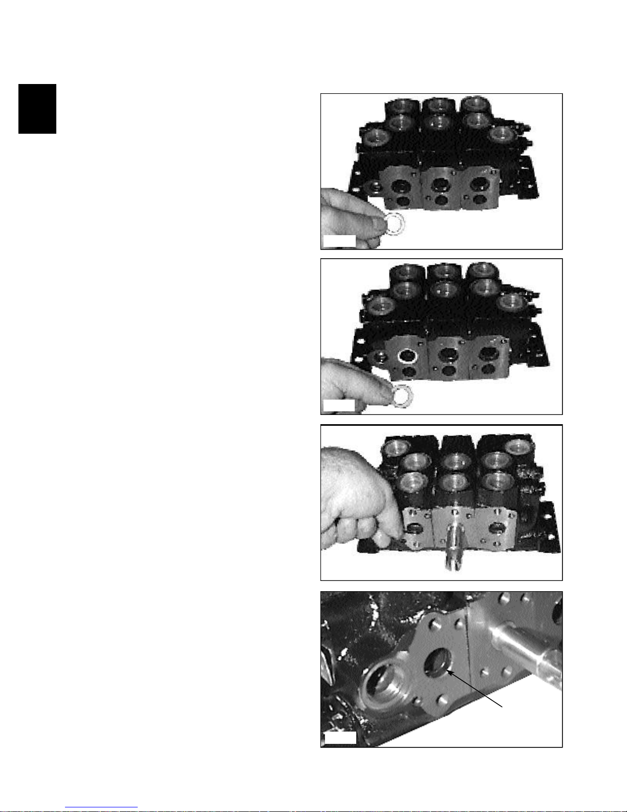
19 The auxiliary section, section without lock adapter,
has an O-ring seal located in a machined groove in the
section housing. (fig. C2386) Remove the seal using a
pick tool and replace with new. Lubricate the O-ring with
system oil. Figure C2387 shows the seal installed.
C2385
C2386
1-18
Seal
C2387
Page 31

CONTROL VALVE 1.3
1
Disassembly / Repair (cont’d)
20 Section seals may be replaced without removing
spools and spring return mechanisms. Loosen the bolts
retaining the control valve sections together. (fig. C2388).
Upon assembly follow the torque specifications given
Section 8.
Loosen section bolts
C2388
21 Note the flat spacer washers used on the upper bolts.
(fig. C2389)
22 Remove the bolts and mounting brackets. (fig.
C2390)
Flat spacer washer
C2389
Mounting bracket
23 Separate the control valve sections. (fig. C2391)
C2390
Separate sections
C2391
1-19
Page 32

CONTROL VALVE 1.3
Disassembly / Repair (cont’d)
24 Remove and discard the O-ring seals between the
sections. Replace with new. Be sure to replace the O-ring
seal spacer shim upon assembly. (fig. C2392, C2393).
Lubricate the seals with system oil upon assembly. When
reassembling the control valve sections, follow the torque
specifications in Section 8.
O-ring seals
Spacer shim
C2392
O-ring seals
Spacer shim
25 To remove the detent mechanism and spring from the
spool, place an allen wrench or screwdriver blade through
the spool eyelet to hold the spool from turning while
removing the spring and detent mechanism. (fig. C2394).
26 Remove the mechanism and arrange the parts in
order of placement. (fig. C2395) Inspect the detent part
and bushings for burrs and wear. Replace if worn.
C2393
Removing spring assembly
C2394
Exploded view of spring and
detent assembly
Spool bores
1-20
C2395
Page 33

CONTROL VALVE 1.3
1
Disassembly / Repair (cont’d)
27 Replace the spring and detent mechanism in the
reverse order. (fig. C2396). Install spring bushing.
Lubricate the spring bushings with Castrol Spheerol
grease or equivalent.
28 Install sleeve bushing. (fig. C2397). Lubricate the
bushing with Castrol Spheerol grease or equivalent.
Spring bushing
C2396
29 Install the spring, spring bushing and detent. (fig.
C2398) Install the bolt. Apply Loctite 242 (blue) to the
threads and tighten to specifications given in Section 8.
30 To service the spring return mechanism in the cover,
remove the circlip retaining the cover. (fig. C2404).
Sleeve bushing
C2397
Spring
Detent
Spring bushing
Bolt
C2398
Remove circlip
C2404
1-21
Page 34

CONTROL VALVE 1.3
Disassembly / Repair (cont’d)
31 Remove the cover. (fig. C2405).
32 Remove the spring washer. (fig. C2406).
Remove cover
C2405
Remove washer
33 Remove the spring. (fig. C2407). Inspect the spring
for broken or sacked coils. Replace the detent spring
return with a new kit if spring damage is apparent.
34 Remove the detent ball sleeve and cup. (fig. C2408).
C2406
Remove spring
C2407
Remove sleeve
and cup.
1-22
C2408
Page 35

1
CONTROL VALVE 1.3
Disassembly / Repair (cont’d)
35 Separate the sleeve and cup assembly. (fig. C2409).
Inspect the tapered cup, balls and sleeve for wear.
Replace with new detent kit assembly if wear is evident.
36 Remove the spring washer. (fig. C2410).
37 Clean all parts with solvent. Lubricate all parts with
Castrol Spheerol grease or equivalent.
Inspect cup, sleeve and balls
C2409
Remove washer
C2410
38 Replace the greased detent balls to the cup and sleeve
(fig. C2411) and reassemble the complete spring return
mechanism in the reverse order above.
39 The grease holds the detent balls in position during
assembly to the control valve and spool. (fig. C2412)
40 Replace the cap assembly to the control valve and
tighten the screws evenly.
IMPORTANT
Check to make sure the detent balls are in position
before assembling to the control valve to assure
proper function of the control spool and detent
mechanism.
Grease detent and balls
C2411
Detent balls in
position
C2412
1-23
Page 36

THOMAS
1-24
Page 37

1
CONTROL VALVE 1.3
Screw
Screw
Bushing
Spring
Bushing
Screw
Cap
Cap
Block
Detent
Spring
Screw
Washer
Cap
Spring
Bushing
Bushing
Ball Holder
Block
Detent
Walvoil Model, S / N LC0001081 onward
Spring
Check Valve
Anti-cav
Main Body
Relief Valve
O-ring
Tilt
Spool
O-ring
Seal Washer
Lift Spool
Lock Pin
Scraper
Seal
Nut
O-ring
Coil
O-ring
Post
Spring
Lock Block
Screw
Cover
Scraper Seal
Aux. Spool
Cover
C2776
1-25
Page 38

CONTROL VALVE 1.3
Disassembly / Repair
Before disassembling the hydraulic control valve, clean
the body with a suitable solvent and dry with compressed
air.
To avoid eye injury, use
WARNING
Ensure all openings are plugged to prevent solvents and
dirt from contaminating the control valve assembly. Refer
to diagram C2776, pg. 1-25, to assist in the disassembly
of the control valve.
1 Remove the pressure relief valve. Discard the Orings (fig. C2975).
safety goggles when cleaning with compressed air.
Removing the relief valve
O-ring seal
C2975
Removing the solenoid coils from the spool locks
O-ring seal
2 Remove the solenoid coils and locking pin from the
valve lock block. (fig. C2235, C2236) There are 2 O-ring
seals located on either side of the solenoid coils.
3 Remove the outer wiper seal cover from the lock
block. (fig. C2244)
C2235
Removing the lock from the valve
Spring
Lock pin
C2236
Wiper seal cover
1-26
Wiper seal
C2244
Page 39

CONTROL VALVE 1.3
1
Disassembly / Repair (cont’d)
4 Remove the lock block from the valve. (fig. C2241)
C2241
5 Remove the spring return / centering cap from the
end of the spool. (fig. C2237)
6 Pull out the spool. (fig. C2240) As you pull out the
spool, note it’s smooth action as it comes out of the valve
body. The spool should move freely and smoothly in the
bore of the valve body. Check the control valve spool and
bore for scuff marks or abnormal wear. Replace the spool
and or control valve if signs of wear are present.
Remove the spring centering / return assembly
C2237
Removing the spools from the valve
Seal washer
O-ring seal
7 Remove the check valves from control valve body.
(fig. C2239) They are located between the ports of each
section. Check the seat and poppet of the valve body and
check valve. Replace the check valve and or the control
valve if any signs of wear are present.
C2240
Remove the check valves
Inspect tapered seats
C2239
1-27
Page 40

CONTROL VALVE 1.3
Disassembly Repair (cont’d)
8 When replacing the spool to the control valve, use
new O-ring seals and apply system oil to the O-rings and
spools. (fig. C2251).
9 Fit the seal washer to the control valve with the
beveled side of the washer facing the control valve. (fig.
C2252) Fit the spool to the control valve now if repairs
are not needed to the detent or spring return mechanism.
Use system oil to lubricate the spool before inserting to
the control valve.
10 Photographs C2238, C2242 are exploded views of
the lift spool detent mechanism. Place the cable end of
the spool in a vice, or insert a screw driver through the
clevis pin holes, to keep it from turning. The detent is
threaded to the spool and can be removed for inspection
or repairs.
Replace broken springs, worn detents and / or damaged
detent balls with a new detent kit.
Apply Loctite 542 to the threads of the detent when
installing to the spool.
Apply Castrol “Spheerol” TN grease to the inside of the
spring cover.
C2251
Beveled seal washer
C2252
Spool
Apply Loctite 542
C2238
Spool O-ring
Spool spring
and bushings
Detent
1-28
Center return cover
Detent ball carrier
Tapered
cup
Detent balls
C2242
Page 41

1
CONTROL VALVE 1.3
C2249
C2250
O-Ring and seat
O-Ring and seat
Spool bores
Disassembly / Repair (cont’d)
11 When installing the detent to the control valve spool,
apply Loctite type 252 to the threads. Tighten the detent
to the spool at 24 Nm (17.7 lbs / ft).
12 Install the spring return / centering cover and tighten
the mounting screws evenly to 6.6 Nm (4.9 lbs / ft).
Install the end cap to the cover and tighten to 9.8 Nm
(7.2 lbs / ft).
Apply Loctite 252
C2254
Detent spring and cap
C2258
1-29
Page 42

HYDRAULIC CYLINDERS 1.4
Lift cylinder shown
15
C1179
14
7
6
5
4
3
8
2
9
10
11
12
13
1. O-ring 9. Piston part “B” (front)
2. Wiper seal 10 Grease fitting
3. Rod seal 11. Cylinder barrel
1
4. Gland O-ring 12. Gland nut
5. Wear ring 13. Cylinder rod
6. Piston seal 14. Lock nut
7. Wear ring 15. Grease fitting
8. Piston part “A” (rear)
General Information
All cylinders are a double acting, designed to extend and
retract under pressure.
The piston rods, which are made of high strength
distortion free material, are precision ground and hard
chrome plated. The cylinders barrels are micro honed to
close tolerance,straightness and smooth finish for long
piston packing seal life.
All cylinders have a 2 piece piston assembly made of
ductile iron and a polypac seal arrangement consisting of
a piston seal and 2 wear rings.
The rod seal is a “U” cup design, with the “U” facing the
pressurized oil.The rod wiper keeps foreign matter from
entering the cylinder by wiping the rod clean as the
cylinder retracts.
1-30
The gland nut seal is of an “O” - ring design. This seal
keeps the oil from leaking around the gland nut and
cylinder barrel threads.
Certain cylinders have spacers in them. These spacers are
used to limit the stroke of the rod.
Some cylinders also have replaceable hardened bushings
in the pivot areas that can be serviced when worn out.
Page 43

HYDRAULIC CYLINDERS 1.4
1
Testing the Piston Seals
If the boom or bucket cylinders drift down with the
control valve spools in the neutral position, and with no
external leaks in the hydraulic system, the following test
will indicate if oil is leaking by the cylinder piston seals.
With the hydraulic oil at operating temperature and a
fully loaded attachment, check that the cylinders do not
drop more than 1.5 inches every 3 minutes with the
engine off. Before performing this test, ensure the control
linkages are not binding and the hydraulic control valve
spools are centering in the neutral position. If the test has
proven excessive leak down the cylinders may be further
tested in the following manner.
IMPORTANT
Allowable boom or bucket cylinder drop: 1.5’’ in
3 minutes, @ loaded rating and operating
temperature.
Fixed end
C2356
Fixed end
WARNING
Never repair or tighten hydraulic lines while the
engine is operating or the system is under pressure.
1 This test must be performed with the engine running.
Remove any attachment and block the loader securely
with all 4 wheels off the ground.
2 Retract the cylinder(s) to be tested. Shut off the
engine and cycle the controls to release the hydraulic
pressure.
3 Disconnect the hose from the fixed end of the
cylinder to be tested. Cap the hose with a steel plug to
prevent system charge pressure from escaping the open
circuit and to prevent contamination.
4 Start the engine and cycle the control(s) as to retract
the cylinder. Do not over activate the controls as to place
in the detent position. Have a container can ready to catch
any waste oil to prevent environmental contamination.
5 Repeat for all both cylinders.
6 If oil leaks from the cylinder port the seals are bad
and need replacement. If no oil leaks you may need to
check the load check valves or spool wear in the
hydraulic control valve.
7 Connect the hydraulic hose to the cylinder ports if no
further servicing is required.
C2351
WARNING
Use extreme caution when checking the hydraulic
system for leaks. Fluid under pressure can penetrate
the skin and cause serious injury. Never use your
hands to check for leaks.
Hydraulics under liftarm step
C1336
1-31
Page 44

HYDRAULIC CYLINDERS 1.4
Lift Cylinder Replacement
IMPORTANT
When making repairs to the hydraulic system, keep
the work area and parts clean. Use caps and plugs on
all open lines and ports.
The following procedure will assist you in the cylinder
removal.
For removal of the boom cylinders:
1 Lower the boom arms, stop the engine and cycle the
controls to relieve any hydraulic back pressure in the
system. Lock the control in the float or detent position.
2 Remove the hydraulic hoses from the cylinder. (fig.
C2356) Cap all open ports and lines to prevent
contamination.
3 Remove the lock nut and bolt from both mounting
pins. (fig. C2413, C1864)
4 Remove the front pivot pin by pushing the pin out
from behind the boom arm, out toward you. (fig. C1876)
With an appropriate punch and hammer to prevent
brooming of the pin, remove the rear pin. (fig. C1877)
Brooming the pin makes it difficult to remove.
Disconnect hoses
C2356
Remove bolt
C2413
Remove front pin
5 Remove the cylinder from the loader.
6 Upon replacement, inspect the pivot pins and
cylinder bushings for any wear. Replace if necessary.
Reverse order above for installation.
7 Upon start up, check for system leaks and replenish
the hydraulic reservoir as required.
WARNING
Use extreme caution when checking the hydraulic
system for leaks. Fluid under pressure can penetrate
the skin and cause serious injury. Never tighten or
repair hydraulic lines while the engine is operating.
C1876
Remove rear pin
C1877
1-32
Page 45

1
HYDRAULIC CYLINDERS 1.4
Tilt cylinder Replacement
For tilt cylinder removal:
1 Lower the boom arms, remove any attachment and
extend the tilt cylinders. Shut off the engine and cycle the
controls to relieve excessive back pressure in the
hydraulic system.
2 Loosen or remove the hydraulic hoses from hydraulic
tubing under the boom arm step if you are changing the
hoses also. (fig. C1336)
3 Remove the hydraulic hoses from the tilt cylinder.
Plug and or cap all open ports or lines to prevent
contamination. (fig. C2414a)
4 Remove the lock nuts from the bolts retaining the
pivot pins to the loader and remove the bolts. (fig.
C2414)
5 Remove the pivot pins.
6 Remove the cylinder from the loader.
7 Upon reassembly, inspect the pivot pins and bushings
for wear and replace as required. Reverse order for
cylinder installation.
Bolts
C2414
Hoses underneath the boom arm step area
C1336
8 Upon start up, check for system leaks and replenish
the hydraulic oil reservoir as required.
WARNING
Use extreme caution when checking the hydraulic
system for leaks. Fluid under pressure can penetrate
the skin and cause serious injury. Never tighten or
repair hydraulic lines while the engine is operating.
Remove hoses
C2414a
1-33
Page 46

HYDRAULIC CYLINDERS 1.4
Cylinder Disassembly
Before Attempting repairs to the hydraulic cylinder, clean
the body with a suitable solvent. Ensure all openings are
plugged to prevent solvent from entering the cylinder.
1 Remove the cylinder as outlined previously.
2 Place the base end of the cylinder in a vise and
support the front end of the body. Remove the plugs from
the hose ports. (fig. C125)
3 Loosen the gland nut from the cylinder barrel using a
spanner wrench. The gland nut threads are coated with
loctite bonding agent at time of assembly. It may be
necessary to apply heat to the gland nut and cylinder
barrel threaded area, with a torch, to ease removal. (fig.
C125)
4 Remove the gland nut, rod and piston seal assembly
from the barrel. (fig. C329)
5 Place the cylinder rod bushing end in a vise and
remove the lock nut from the rod. (fig. C128)
C125
C329
Remove lock nut
6 Remove the 2 piece piston assembly from the rod.
(fig. C126)
7 NOTE: Some piston assemblies rear piston parts are
threaded onto the rod. You will need to use a spanner
wrench to remove this type of rear piston.
1-34
C128
C126
Page 47

HYDRAULIC CYLINDERS 1.4
1
8 Depending on the design of the rear piston, non
threaded type, remove and discard the o-ring seal from
the end of the cylinder rod. (fig. C127)
9 Remove the gland nut assembly from the cylinder
rod. (fig. C330)
O-ring seal
C127
10 Remove and discard the wiper seal, rod seal and oring seals and teflon back up washer, (if used), from the
gland nut assembly. (fig. C612) NOTE: Some seal
designs may vary from illustration
11 Remove and discard the wear rings and piston seal
from the piston assembly. (fig. C130)
Gland nut
C330
Gland o-ring
Gland nut
Wiper seal
Back up
washer
Rod seal
C612
C130
1-35
Page 48

HYDRAULIC CYLINDERS 1.4
Cylinder Inspection
1 Inspect the cylinder rod for scratches, dents and other
damage. Minor rod damage may be repaired using a fine
abrasive. Major scratches or dents are not repairable and
the rod must be replaced. The chrome surface must be
intact to provide a rust resistant surface. Blemishes on the
rod will damage the rod seal and wiper and will cause
leaking after a short period of use.
2 Inspect the cylinder rod threads. The threads must be
in good condition to withstand the high torque required to
secure the piston assembly to the rod.
3 Inspect the gland nut for nicks, burrs or other
damage. Minor damage may be repaired using a fine
abrasive.
Cylinder Assembly
1 Install a new gland nut rod seal. Form the seal into
an oval shape and place it into the gland nut, with the “U”
side of the seal facing the barrel end, and slip the seal into
the groove. (fig. C129, C131)
Smooth down edges that could damage seals and cause
leakage.
4 Inspect the gland nut threads for damage.
5 Inspect the piston assembly for damage. Remove
minor scratches or damage with a fine abrasive.
6 Using a suitable light, inspect the cylinder barrel bore
for scratches, dents, burrs or any other damage. Replace
the cylinder barrel if there is any evidence of damage.
7 Inspect the cylinder barrel threads for damage. The
threads must be in good condition to withstand the high
torque required to secure the gland nut assembly to the
cylinder barrel.
2 Install a new wiper seal in the gland nut. (fig. C129,
C131)
3 Install a new gland nut o-ring seal. (fig. C129, C131)
4 Apply system oil to the cylinder rod and assemble
the gland nut assembly to the rod. (fig. C132)
C129
C131
1-36
C132
Page 49

HYDRAULIC CYLINDERS 1.4
1
5 Install a new o-ring seal on the cylinder rod if used.
Some cylinder rod are fully threaded here to
accommodate a threaded type rear piston part. (fig. C133)
6 Install new wear rings and piston seal to the the 2
piece piston assembly. (fig. C130)
C133
7 Install the piton assembly to the cylinder rod. Some
rear piston assemblies are threaded onto the cylinder rod.
Use a spanner wrench to install the rear piston part to the
cylinder rod. Torque the lock nut to the rod at 150 ft / lbs
(204 N.m.). (fig. C128)
8 Make sure the inside bore of the cylinder barrel is
clean. Lubricate the inside of the barrel with system oil.
Do not get oil into the threaded area of the barrel.
9 Lubricate the piston seal assembly with system oil
and install the cylinder rod and piston assembly to the
cylinder barrel. (fig. C329)
10 Apply loctite 242 to the gland nut threads and tighten
the gland nut using a spanner wrench. Tighten the gland
nut as much as you can using the spanner wrench. Make
sure the threaded area of the gland nut and cylinder barrel
are free of oil before applying the loctite bonding
adhesive.
11 Assemble the cylinder to the loader. Use teflon tape
or equivalent on the threads of the hydraulic hose ends, if
the hose ends are of the taper pipe thread type.
C130
C128
C329
1-37
Page 50

HYDRAULIC OIL FILTER 1.5
General Information
The hydraulic oil filter is located in the engine
compartment, accessed by opening the rear door and
lifting the engine compartment cover. The filter is
mounted on the left side, on the oil reservoir.
All oil returning from the control valve is filtered before
being used up by the hydraulic system.
The hydraulic oil filter is a spin on type with a 10 micron
rating. The filter material is a resin impregnated cellulose
which features an accordion pleated design to provide
maximum filtration area. Only Thomas approved filters
should be used.
The filter mounting head has a built in bypass valve that
diverts oil around the filter when more than 25 psi (34
nm) differential pressure is required to force oil through
the filter.
Filter Replacement
The hydraulic oil filter must be changed after the first
50 hours of operation and every 150 hours thereafter,
or sooner if the pressure gauge dictates.
1 Lower the boom arms, shut off the engine and
engage the parking brake.
2 Open the rear door and raise the engine compartment
cover to gain access to the hydraulic filter. (fig. C2347,
C2354)
3 Clean the area of excess dirt if necessary to prevent
contaminating the new filter when installing
4 Remove the hydraulic oil filter using a proper sized
filter wrench. Check to make sure the o-ring seal has
come off with the used filter. (fig. C1868)
5 Lubricate the new filter seal with clean system oil.
6 Install the filter and fit hand tight.
7 After start up, check the system for oil leaks.
Replenish the oil reservoir as required with API 10W30
class SE / CD. (fig. C892, C1108)
Access the engine compartment
C2347
Pressure gauge
Hydraulic oil filter
Oil level site gauge
C2354
Check seal
C1868
Filler cap
WARNING
Never repair or tighten hydraulic lines while the
engine is operating or the system is under pressure.
1-38
Oil level
site gauge
C1108C892
Page 51

HYDRAULIC OIL COOLER 1.6
1
General Information
The hydraulic oil cooler is mounted to the inside of the
rear door. (fig. C2932) Oil returning from the control
valve is circulated through the oil cooler before being
sent on to other parts of the hydraulic system.
An engine driven cooling fan drives air through the oil
cooler when the rear door is closed.
The oil cooler is rated at 250 BTU / minute.
The oil cooler should be checked daily for dirt build up
on the cooling fins. If air flow is restricted through the
cooling fins, over heating of the hydraulic system may
occur. Clean any dirt build up with compressed air. Flush
with water if necessary.
To avoid eye injury,
WARNING
Cooler Replacement
1 Lower the boom arms, engage the parking brake and
shut off the engine.
2 Open the rear door.
3 Connect a vacuum system to the oil reservoir filler
spout, if available, or drain the hydraulic oil reservoir. Be
prepared to contain 34 liters of fluid (9 gal). Use clean
containers if the oil is to be reused.
4 Remove the cooler hoses. Plug the open hoses and
cooler ports to prevent contamination.
5 Remove the cooler from the rear door.
6 Remove the fittings from the oil cooler.
7 Inspect the fitting o-rings for damage and replace if
necessary.
8 Install the fittings into the new or repaired oil cooler
following the torque chart on section 1.10. Be sure to
support the cooler as the fittings are tightened to prevent
damaging the cooler.
9 Replace the cooler & cooler lines. Follow the torque
chart on section 1.10 when tightening the hydraulic hoses.
10 Replenish the hydraulic fluid as required. Check for
system leaks and check the fit of the shroud seal to the
engine radiator. Adjust if necessary.
always use safety goggles
when cleaning with
compressed air.
C2932
Engine driven cooling fan
C1872
Upper Radiator Mount
C2933
1-39
Page 52

HYDRAULIC OIL RESERVOIR 1.7
General Information
The hydraulic oil reservoir is located at the rear of the
loader on the left hand side. (fig. C2934) The reservoir is
completely separated from all chain and gear drives to
eliminate contamination. A magnetic drain plug is
installed in the bottom of the reservoir, and a magnet is
attached to the 100 micron suction filter, to assist in
removing metal particles from the oil.
Oil level is checked through a site gauge located just
inside the engine compartment, left hand side, on the oil
reservoir. The proper fill level is marked by a line and
should be checked daily. (fig. C2354)
The oil reservoir fill cap is located at the top of the
reservoir. (fig. C2355) The oil fill cap assembly has a 30
micron screen to catch larger particles of contaminant
before entering the reservoir, but always use oil filtered
through a 10 micron min. filter for replenishing the
hydraulic reservoir. The oil fill cap is also a reservoir
vent, or breather, and contains a 10 micron filter to
remove air borne particles.
Checking The Oil Level
1 Check the reservoir oil level with the loader on level
ground.
2 Lower the boom arms, retract the cylinders and
engage the parking brake. Shut off the engine.
3 Open the rear door. (fig. C2934)
4 Check the oil level in the sight gauge. (fig. C2354)
5 If oil is visible approximately mid way in the sight
gauge, the level is correct.
Hydraulic oil reservoir
C2934
Reservoir sight gauge
C2354
IMPORTANT
Always use filtered oil to replenish the hydraulic
system.
Adding Oil
1 Remove the bolt, or lock, on the reservoir filler cap.
2 Open the filler cap. (fig. C2355)
3 Inspect the filler screen in the filler neck for damage.
If the filler screen is damaged, replace it.
4 Using a clean container, add 10W30 API class SE /
CD oil.
5 Replace the filler cap and replace the bolt, or
padlock, in the cap to prevent vandalism.
1-40
Reservoir filler cap
C2355
Page 53

HYDRAULIC OIL RESERVOIR 1.7
1
Servicing The Oil Reservoir
Change the hydraulic oil, change the suction screen
element and clean the magnet in the tank after every 1000
operating hours or if the oil has become contaminated or
after any major hydrostatic drive system repair.
1 Lower the boom arms, shut off the engine and
engage the parking brake.
2 Remove the magnetic drain plug located at the
bottom of the hydraulic oil reservoir. (fig. C1034) Clean
any metal particles that may be attached to the magnet.
Have containers ready to hold approximately 10 gallons
(45 £) of fluid. Replace the drain plug using teflon sealing
tape or liquid type sealant on the plug threads.
3 Access the suction screen element in the hydraulic
reservoir by removing the inspection cover on the
reservoir, located in the engine compartment. (fig. C2357)
Clean the excess silicone from the cover and reservoir.
Hydraulic reservoir drain
C1034
Hydraulic reservoir inspection cover
4 Remove the suction screen element from the
reservoir by turning counter clockwise. (fig. C1769,
C1777)
5 Remove and clean the magnet attached to the suction
element. (fig. C1769)
6 Install the magnet onto a new suction element and
install the suction element.
7 Apply silicone around the inspection hole and install
the inspection cover to the reservoir. Do not over tighten
the mounting nuts. Maximum torque is 18 ft / lbs (24
N.m.).
8 Fill the reservoir to the proper level with 10W30 API
classification SE / CD oil, approximately 13 gallons or 50
liters.
C2357
Suction element
Magnet
C1769
Suction element
C1777
1-41
Page 54

TROUBLE SHOOTING 1.8
Problem Cause Corrective Action Section
Loss of hydraulic
power (no flow from
the gear pump).
Loss of hydraulic
power (full flow from
gear pump).
Hydraulic action jerky. Reservoir low on oil. Check for leaks. Fill the reservoir to the proper level. 1.8
Boom raises slowly at
full RPM
Hydraulic cylinders
will not support a load.
(leak down)
Reservoir low on oil. Check for leaks. Fill the reservoir to the proper level. 1.8
Universal joint between
engine and tandem
pump failure.
Gear pump not
functioning.
Splined coupling
failure in the
hydrostatic pump
Electrical failure. Check fuse, switches and wiring.
Auxiliary hydraulics
engaged.
Relief valve failure or
out of adjustment.
Control locks engaged Check fuse, safety switches and valve lock parts.
Control linkages loose
or worn.
Air in hydraulic
system.
Load check valve not
functioning.
Control valve spool
spring return mechanism not functioning
Reservoir low on oil. Check for leaks. Fill the reservoir to the proper level.
Control linkages loose
or worn.
Auxiliary hydraulics
engaged.
Lifting more than rated
capacity.
Engine RPM too low. Check engine RPM and reset.
Relief valve failure or
out of adjustment.
Cylinder seal(s) failure.
Internal leakage in the
control valve.
Control valve spools
not centering.
External leak between
control valve and
cylinders
Cylinder seal(s) failure
Load check valve not
functioning.
Inspect and replace the damaged parts as required.
Check for proper alignment.
Inspect and replace damaged parts.
See the Sauer Sundstrand Repair Manual BLN 9992.
Disengage the switch.
Check pressure. Adjust or repair as required. 1.4
Inspect, adjust or replace parts.
Check for leaks between the oil reservoir and pump.
Inspect and replace damaged parts. 1.4
Inspect and replace damaged parts. 1.4
Inspect, adjust or replace parts. 4
Disengage the switch.
Reduce the load.
Check pressure. Adjust or repair as required. 1.4
Check seals.
Inspect the control valve and repair as required. 1.4
Check control linkage and control valve spool spring
centering devise.
Inspect and repair.
Check seals.
Inspect and replace damaged parts.
7.11
1.4 / 2.9
2.10
8
4.9
1.4 / 8
4
1.8
4.9
7.11
1.5
1.4 / 4
1.5
1.4
1-42
Page 55

TROUBLE SHOOTING 1.8
1
Problem Cause Corrective Action Section
Hydraulic oil
overheating.
Reservoir low on oil. Check for leaks and replenish as required. 1.7
Oil cooler plugged or
dirty. (if applicable)
Auxiliary hydraulics
engaged.
Temperature sender
defective.
Relief valve failure or
out of adjustment.
Wrong type of
hydraulic fluid.
Clean the cooling fins.
Disengage.
Replace.
Check pressure, adjust or replace.
Replace.
8
1.4
1.7
TORQUE CHART 1.9
Hydraulic Hose and Fitting Torque Chart
NOTE: all torques are in lbs. / ft (Multiply by 1.36 = N.m.)
HOSE SIZE 37º JIC FITTINGS HOSE SIZE ORB FITTINGS
1/4 9 to 10 1/4 14 to 16
5/16 15 to 16 5/16 18 to 20
3/8 20 to 22 3/8 24 to 26
1/2 30 to 33 1/2 50 to 60
5/8 40 to 44 5/8 72 to 80
3/4 70 to 77 3/4 125 to 135
7/8 82 to 90 7/8 160 to 180
1 55 to 60 1 200 to 220
1 1/4 120 to 132 1 1/4 210 to 280
1 1/2 131 to 144 1 1/2 270 to 360
2 300 to 330
The following torque specifications are for steel ORB fittings into aluminum.
HOSE SIZE ORB FITTINGS HOSE SIZE ORB FITTINGS
1/4 5 to 7 3/4 40 to 45
5/16 8 to 10 7/8 50 to 55
3/8 10 to 12 1 90 to 99
1/2 21 to 24 1 1/4 80to 90
5/8 27 to 30
1-43
Page 56

NOTES
THOMAS
1-44
Page 57

2
SECTION 2
HYDROSTATIC DRIVE SYSTEM
Hydrostatic Drive Circuit . . . . . . . . . . . 2.1
Schematic . . . . . . . . . . . . . . . . . . . . . . . . . . . . . . . . . . . . . . . . . . . pg. 2-2
Specifications . . . . . . . . . . . . . . . . . . . . 2.2
Chart . . . . . . . . . . . . . . . . . . . . . . . . . . . . . . . . . . . . . . . . . . . . . . pg. 2-3
General Information . . . . . . . . . . . . . . . 2.3
Introduction . . . . . . . . . . . . . . . . . . . . . . . . . . . . . . . . . . . . . . . . . pg. 2-4
Trouble Shooting . . . . . . . . . . . . . . . . . 2.4
Chart . . . . . . . . . . . . . . . . . . . . . . . . . . . . . . . . . . . . . . . . . . . pg. 2-5 ~ 7
Diagnose Steps . . . . . . . . . . . . . . . . . . . . . . . . . . . . . . . . . . . . . . pg. 2-8
Pressure Tests . . . . . . . . . . . . . . . . . . . . 2.5
Procedure . . . . . . . . . . . . . . . . . . . . . . . . . . . . . . . . . . . . . . . . . . . pg. 2-9
Towing Procedure . . . . . . . . . . . . . . . . . 2.6
Procedure . . . . . . . . . . . . . . . . . . . . . . . . . . . . . . . . . . . . . . . . . . pg. 2-10
Flushing The Hydraulic System . . . . . . 2.7
General Information . . . . . . . . . . . . . . . . . . . . . . . . . . . . . . . . . pg. 2-11
Cleaning . . . . . . . . . . . . . . . . . . . . . . . . . . . . . . . . . . . . . . . . . . . pg. 2-12
Start-up Procedure . . . . . . . . . . . . . . . . 2.8
Procedure . . . . . . . . . . . . . . . . . . . . . . . . . . . . . . . . . . . . . . . . . . pg. 2-14
Gear Pump Replacement . . . . . . . . . . . 2.9
Procedure . . . . . . . . . . . . . . . . . . . . . . . . . . . . . . . . . . . . . . . . . . pg. 2-15
Tandem Pump Replacement . . . . . . . . 2.10
Removal . . . . . . . . . . . . . . . . . . . . . . . . . . . . . . . . . . . . . . . . . . . pg. 2-16
Installation . . . . . . . . . . . . . . . . . . . . . . . . . . . . . . . . . . . . . . . . .pg. 2-17
Tandem Pump Parts Diagram . . . . . . . 2.11
Parts Illustrations . . . . . . . . . . . . . . . . . . . . . . . . . . . . . . . . pg. 2-20 ~ 23
Drive Motor . . . . . . . . . . . . . . . . . . . . 2.12
General Information . . . . . . . . . . . . . . . . . . . . . . . . . . . . . . . . . pg. 2-24
Removal . . . . . . . . . . . . . . . . . . . . . . . . . . . . . . . . . . . . . . . . . . . pg. 2-28
Replacement . . . . . . . . . . . . . . . . . . . . . . . . . . . . . . . . . . . . . . . pg. 2-30
Parts Illustration . . . . . . . . . . . . . . . . . . . . . . . . . . . . . . . . pg. 2-32 ~ 33
Disassembly . . . . . . . . . . . . . . . . . . . . . . . . . . . . . . . . . . . . . . . . pg. 2-34
Assembly . . . . . . . . . . . . . . . . . . . . . . . . . . . . . . . . . . . . . . . . . . pg. 2-42
2-1
Page 58

HYDROSTATIC CIRCUIT 2.1
Hydrostatic Circuit Schematic
C1007
2-2
Page 59

2
SPECIFICATIONS 2.2
Hydrostatic Tandem Pump
Pump Type . . . . . . . . . . . . . . . . . . . . Variable Displacement, Reversible Piston
Brand Name of Pump . . . . . . . . . . . . . . . . . . . . . . . . . . . . . . . Sauer Sundstrand
Series / Model Type . . . . . . . . . . . . . . . . . . . . . . . . . . . . . . . . . . . . 40 / M25 PT
No. Of Drive Pumps . . . . . . . . . . . . . . . . . . . . . . . . . . . . . . . . . . . . . . . 2 (TWO)
Mounting . . . . . . . . . . . . . . . . . . . . . . . . . . . . . . . . . . . . . . . . . . . . . . . . Tandem
Rotation (viewed from shaft end) . . . . . . . . . . . . . . . . . . . . . . . . . . . Clockwise
Operating Speed . . . . . . . . . . . . . . . . . . . . . . . . . . . . 3000 RPM (+ / - 50 RPM)
Pump Displacement . . . . . . . . . . . . . . . . . . . . . . . . . . . . . . . . . 1.5 cu. in. (25cc)
Minimum Pump Output (flow) . . . . . . . . 9.5 gal. (36L) / Minute @ 1800RPM
. . . . . . . . . . . . . . . . . @ 2000 PSI (137.8 Bar) Over Measured Charge Pressure
No. Of Relief Valves . . . . . . . . . . . . . . . . . . . . . . . . . . . . . . . . . . . . . . 2 (TWO)
Relief Valve Setting . . . . . . . . . . . . . . . . . . . . . . . . . . . . . . . 250 Bar (3625 PSI)
Max. Allowable Case Pressure . . . . . . . . . . . . . . . . . . . . . . . . . 25 PSI (1.7 Bar)
Charge Pump Type . . . . . . . . . . . . . . . . . . . . . . . . . . . . . . . . . . . . . . . . . . . N / A
Charge Pressure . . . . . . . . . . . . . . . . . . . . . . . . . . . . . . 200 PSI Min. (13.8 Bar)
Hydrostatic Repair Manual . . . . . . . . . . . . . . . . . . . . . . . . Thomas P / N 44232
. . . . . . . . . . . . . . . . . . . . . . . . . . . . . . . . . . . Sauer Sundstrand P / N BLN-9992
Hydraulic Drive Motor
Drive Motor Type . . . . . . . . . . . . . . . . . . . . . Geroler Torque Motor With Brake
Brand Name . . . . . . . . . . . . . . . . . . . . . . . . . . . . . . . . . . . . . . . . . . . . . . Danfoss
Series Type . . . . . . . . . . . . . . . . . . . . . . . . . . . . . . . . . . . . . . . . . OMT 315 FLV
Rotation . . . . . . . . . . . . . . . . . . . . . . . . . . . . . . . . . . . . . . . . . . . . . . . . . . . . Dual
No. Of Drive Motors . . . . . . . . . . . . . . . . . . . . . . . . . . . . . . . . . . . . . . 2 (TWO)
Drive Motor Displacement . . . . . . . . . . . . . . . . . . . . . . . 19.9 cu. in. (326.3cm3)
Max. Case Pressure . . . . . . . . . . . . . . . . . . . . . . . . . . . . . . . . . 25 PSI (1.7 Bar)
Reservoir
Fluid Type . . . . . . . . . . . . . . . . . . . . . . . . . . . . . . 10w30 API Class SE / CD Oil
Capacity . . . . . . . . . . . . . . . . . . . . . . . . . . . . . . . . . . . . . . . . . . . . 11.3 gal (43L)
Reservoir Filtration . . . . . . . . . . . . . . . . . . . . One 100 Micron Screen Element
Hydraulic Oil Filtration . . . . . . . . . . . . . . . . . . . . . . . . One 10 Micron Element
Hydraulic Element . . . . . . . . . . . . . . . . . . . . . . . . . . . . . . . . . . . . . . P / N 35243
2-3
Page 60

GENERAL INFORMATION 2.3
Clockwise input
shaft rotation
High pressure
C1700
Counterclockwise
swash plate rotation
Charge pressure inlet
Variable displacement
piston pump
Case drain
High pressure
Case drain
Fixed displacement
drive motor
Counterclockwise
output shaft rotation
The driveshaft of the piston pump is rotated by the
engine. The piston block which is splined to the driveshaft also turns. The piston block, rotating group, consists
of 9 piston assemblies which have free swiveling shoes
swagged on the ball end of each piston assembly. The
shoe end of the piston rides against the smooth machined
surface of the swashplate. With the swashplate in the neutral position, the piston assemblies do not reciprocate in
the piston block, but are rotating. No oil is drawn into or
discharged from the pump. The pump is in a zero displacement position and the loader remains stationary.
With the swashplate in the neutral position the pressure of
the charge oil, which ranges from 200 to 280 psi (13.8 -
19.3 Bar), is able to unseat both check valves and supply
oil to both sides of the pump because of the balance in
pressure. Very little charge oil volume is required in the
neutral position so the excess oil is bypassed over the
charge pressure relief valve and recirculated back to the
reservoir. The oil that leaks internally in the pump and
motor collects in their body housings and is returned to
the reservoir by external case drain in the pump and
motors. This leakage oil is the only oil the charge check
replenishes. This makes the design a closed loop system.
As the steering lever is moved forward, or reverse, the
loader starts a directional movement. As the swashplate
begins to move, the piston assemblies start to reciprocate
in the piston block. As the steering lever continues further
movement the cam angle increases, the pistons recipro cate further, more oil is pumped and the speed of the
loader is increased.
When the swashplate begins to move the check valve on
the discharge, or pressure, side seats because of the higher pressure differential. The other check valve remains
open on the intake or low pressure side to continue sup plying the closed loop system with charge oil.
The drive motor, which is a fixed displacement type,
delivers a constant output torque for a given pressure
throughout the speed range of the motor.
The movement of the pump swashplate, forward or
reverse, controls the direction of the drive motor rotation.
The function of the pressure relief valve is to relieve the
pressure side of the system of excessive high pressure
when the loader encounters a heavy load or stalls out.
When the relief valve senses an over load it unseats,
allowing excess pressure and volume to flow into the low
pressure side of the pump. A small volume of oil starts to
flow across to the other relief valve. This relief valve is
exposed to the low pressure on the intake side of the
pump and is seated by the spring tension within the relief
valve body.
The small volume of oil being bypassed is enough to
unseat the relief valve and let it recirculate back into the
inlet side of the pump. As the pressure continues to build
on the pressure side, a larger volume of oil flows and at a
greater speed through the drilled orifice in the relief valve
cartridge, causing a pressure drop inside the relief valve.
The surrounding pressure is now able to unseat the relief
valve and bypass maximum volume of oil. The system
reliefs function the same for both sides of the system.
2-4
Page 61

2
TROUBLE SHOOTING 2.4
Symptom: Neutral Difficult Or Impossible To Find
Inspect external
control linkage
Defective
Repair or
replace
OK
Inspect servo
control ( if used )
Defective
Repair or
replace
Symptom: System Operating Hot
Check oil level
in reservoir
Inspect heat
exchanger
OKOK
Check charge
pressure
OK
Fill to proper
level
Inspect charge
pump
Repair or
replace
Replace pump
and motor
DefectiveBelow level
Repair or
replace
OK OK
OK
Inspect inlet
screen or filter
CloggedDefective
Replace
Inspect motor
Defective High
Repair or
replace
OK
Low
Inspect charge
relief valve
Defective
Repair or
replace
Check system
pressure
Reduce system
load
2-5
Page 62

TROUBLE SHOOTING 2.4
OK
Symptom: Operates In One Direction Only
Inspect external
control linkage
Defective
Repair or
replace
OK OK
Inspect servo
control ( if used )
Defective
Repair or
replace
Symptom: System Response Sluggish
Check charge
pressure
OK
Inspect servo
control ( if used )
OK
Inspect system
relief valves
Defective
Repair or
replace
Inspect
motor
2-6
Low
Inspect charge
relief valve
Defective
Repair or
replace
Defective
Inspect inlet
screen or filter
Clogged
Replace
Repair or
replace
OK
Inspect charge
pump
Defective
Repair or
replace
Defective
Repair or
replace
OKOK
Replace pump
and motor
Page 63

2
TROUBLE SHOOTING 2.4
Symptom: System Will Not Operate In Either Direction
OK
Check oil level
in reservoir
Below level
Fill to proper
level
Inspect charge
pump
Defective Clogged
Repair or
replace
Replace pump
and motor
OK OK
Inspect motor
Check external
control linkage
Defective
Repair or
replace
Inspect inlet
screen or filter
Replace
OKOK OK
Inspect servo con -
trol ( if used )
OKOK
Check charge
pressure
Low
OK
Inspect charge
relief valve
Defective
Repair or
replace
Check system pressure
Defective Defective High
Repair or
replace
Repair or
replace
Reduce sys-
tem load
2-7
Page 64

TROUBLE SHOOTING 2.4
C1699
C1704
C1698
Pressure gauges
Vacuum gauge
30in. Hg
Adapter fittings
C1697
Caps and plugs
0 - 500PSI (34.5Bar) 0 - 5000PSI (345Bar)
System Diagnosing Steps And Special Tools
1 Check oil level in reservoir:
a .fill to proper level as marked on site tube.
2 Inspect external control linkage for:
a. misadjustment or disconnection
b. binding, bending or breakage
c. misadjusted, damaged or broken hydroback
3 Inspect servo control valve for: (if used)
a. proper inlet pressure
b. misadjusted or damaged neutral return spring
c. galled or stuck control spool
d. galled or stuck servo piston
4 Inspect heat exchanger for:
a. obstructed air flow
b. improper plumbing (inlet to outlet)
c. obstructed fluid flow
5 Inspect inlet filter or screen for:
a. plugged or clogged screen or filter
b. obstructed inlet or outlet
c. open inlet to charge pump (open line)
6 Check charge pressure:
a. follow test procedures section 2.5
7 Inspect charge relief valve for:
a. poppet held of seat
b. damaged or broken spring
c. damaged valve seat
d. improper charge relief setting
8 Inspect charge pump for:
a. broken or missing drive coupling
b. damaged or missing o-rings
c. galled or broken geroter set
9 Inspect system relief valves for:
a. damaged or broken springs
b. valve held of seat
c. damaged valve seat
d. improper pressure relief settings
10 Check system pressure:
a. follow test procedures section 2.5
11 Inspect hydraulic motor for:
a. disconnected coupling
2-8
Page 65

2
PRESSURE TESTS 2.5
The following photos show the various port locations
available on the hydrostatic tandem pump for checking
system pressure.
Completing these pressure test will diagnose any mechan ical problem in the hydrostatic system.
WARNING
Use caution when dealing with hydraulic fluid
under pressure. Escaping fluid under pressure can
penetrate the skin and cause serious injury.
Installing a gauge into the high pressure port ‘A’ or ‘B’ ,
will verify the status of the high pressure relief valves.
Checking the pressure at port ‘C’ will give accurate
charge pressure reading.
Checking the pressure at port ‘D’ will verify case drain
pressure.
Measuring the vacuum at the charge pump inlet can help
locate in in the inlet lines and filters. It would be necessary to tee into the charge pump line fitting.
Snubbers are recommended to protect the gauges from
pressure spikes. Frequent gauge calibration is necessary
to insure accuracy.
Gauge Information
System
A
Pressure
Port ‘A’
System
B
Pressure
Port ‘B’
Charge
C
Pressure
Port
Case
Pressure
D
Port
Charge
Pump Inlet
E
Vacuum
Tandem pump flow can also measure pump performance.
1 Connect a flow meter between the high pressure
ports, one section at a time.
2 Start the engine and increase operating speed
between 1775 ~ 1800 RPM.
3 Restrict the flow to show 2000 PSI (137.8 Bar) over
charge inlet pressure.
Example: Charge pressure = 220 PSI (15.2 Bar) Gauge
pressure reading would need to be 2220 PSI (153 Bar).
4 Minimum flow reading should be 9.5gal / min. (36L /
min).
10,000 PSI Gauge (690 Bar)
9/16 - 18 O-Ring Fitting
10,000 PSI Gauge (690 Bar)
9/16 - O-Ring Fitting
500 PSI Gauge (34.5 Bar)
Tee Into Charge Filter Outlet Line
500 PSI Gauge (34.5 Bar)
1 - 1/16 - 12 O-Ring Fitting
Vacuum Gauge (30 in. Hg)
Tee Into Charge Pump Inlet
C1794
C1795
C1796
Illustrations are of an internal charge pump model.
Actual model in machine may vary.
WARNING
Raise the machine securely from the ground before
performing system checks to prevent sudden movement.
A complete testing kit is available from Thomas, p/n
44365, that contains gauges, hoses and adapters for
Sauer Sundstrand model pumps.
2-9
Page 66

TOWING 2.6
C2359
C2362
Relief valve location
Brake release plunger
Brake valve
2 located bottom side
In an event the loader has malfunctioned or failed, the
loader may be moved a short distance by following the
procedure:
2-10
Page 67

2
FLUSHING THE HYDRAULIC SYSTEM 2.7
General Information
Contamination in the hydraulic system is a major cause of
component failure. Contamination can enter the hydraulic
system in any of the following ways.
1 When draining the hydraulic system.
2 When disassembling components.
3 Making auxiliary connections with dirty couplers.
4 Normal component wear.
5 Component failure
Contamination Types
There are 2 types of contamination, microscopic, or non
visible, and visible. Microscopic contamination is suspended in the fluid and moves freely through the
hydraulic circuits. Examples of problems caused by
microscopic contaminates include the following:
1 Cylinder rod seal leaks.
2 Control valve spools do not return to neutral.
3 Hydraulic system has a high operating temperature.
4 Components wear rapidly.
The best way to remove contaminates from the hydrostatic drive system is to disassemble each component and
flush and clean thoroughly.
The hydraulic control circuits may be cleaned by attaching a suitable hydraulic filter to the auxiliary couplings
and circulating the fluid through it.
Visible contamination is foreign material that can be
found by sight, touch or odor. Some examples of visible
contamination include the following:
1 Particles of metal or dirt in the oil.
2 Air in the oil.
3 Odor of burned oil.
4 Water in the oil.
2-11
Page 68

FLUSHING THE HYDRAULIC SYSTEM 2.7
Cleaning The System
The first step in cleaning the hydraulic system is to determine if you have visible or microscopic contamination.
If the contamination is visible, do the following steps:
1 Change the hydraulic oil by removing the drain plug
in the bottom of the hydraulic oil reservoir. (fig. C1034)
Be prepared to contain approximately 30 litres of fluid.
2 Check the extent of the contamination by disassembling 1 each of the hydraulic cylinders. Check the cylinders for damage. Repair or replace the cylinders as
required. If you determine the damage was caused by
severe contamination and is not the result of normal wear,
it will be necessary to remove, clean and repair all valves,
pumps, lines, cylinders, etc.
3 Replace all hydraulic filters.
If the contamination is determined to be microscopic, perform the following steps:
1 Change the hydraulic oil by removing the plug in the
bottom of the oil reservoir. (fig. C1034) Be prepared to
contain approximately 30 litres of fluid.
2 Connect an external 10 micron filtering system, capable of sustaining minimum of 2000 PSI (138 Bar) and has
a back pressure gauge, to the auxiliary couplings. (fig.
C2351, C1688)
3 Start the engine and let it idle at approximately half
throttle.
WARNING
Hydraulic reservoir
Oil drain plug
C1034
Flush the fluid to an external trap filter
Pressure out
C2351
Replace the hydraulic filter
C1688
Be sure to use a filtering system capable of handling
the pressure of the hydraulic system.
4 Engage the auxiliary circuit. Check to make sure the
filtering system is not over taxed by the loaders hydraulic
system pressure. Adjust engine idle accordingly to match
the filtering systems capacity. This may vary as the filter
becomes dirty, you may need to decrease engine RPM.
Circulate the oil through filter for 30 minutes.
5 As the oil is being circulated through the auxiliary
circuit, raise the liftarms up and down in full stroke
cycles. Repeat this exercise for 15 minutes.
6 Cycle the bucket tilt cylinders in the same manner as
above. Repeat the exercise, in full extension and retraction, for 15 minutes.
7 Install new hydraulic oil filters. (fig. C2354a)
8 Start the engine and check for leaks. Replenish the
hydraulic oil reservoir as required. (fig. C2354b)
2-12
C2354a
Hydraulic reservoir sight gauge
Oil level
C2354b
Page 69

2
FLUSHING THE HYDRAULIC SYSTEM 2.7
For flushing water from the hydraulic system, perform
the following procedures:
WARNING
Be sure attachments are removed and liftarms are
in the lowered position.
1 Remove any attachment.
2 Make sure all cylinders are fully retracted.
3 Change the hydraulic fluid. (fig. C1034)
4 Change the hydraulic filter. (fig. C2354)
5 Disconnect the hydraulic lines from one set of cylinders. (fig. C2356, C1336)
6 Start the engine and set to the lowest idle.
7 Have someone hold the open hydraulic lines into a
container. Stroke the foot pedals, or hand operated, con trols slowly. Continue to repeat this cycle until the oil
comes out clear. Repeat for opposite set of cylinders.
WARNING
Use caution when dealing with hydraulic fluid
under pressure. Escaping fluid under pressure can
penetrate the skin and cause serious injury.
8 Attach a hose and couplings to the auxiliary circuit.
Engage the auxiliary hydraulics, forward and reverse,
until the oil flows clear.
IMPORTANT
Reservoir drain plug
C1034
Replace hydraulic filter
C2354
Disconnect hydraulic lines
Check the hydraulic oil frequently during this procedure. Replenish as required.
9 Connect 1 hose each, on each cylinder, to the fixed
end of the cylinder barrel.
10 Move the foot pedal or control lever to extend the
cylinder rods. This will flush the oil from inside the cylin der barrels. Be prepared to contain the waste oil.
11 Stop the engine.
12 Connect the hydraulic hoses to the rod end of the
cylinder barrel.
13 Replenish the hydraulic oil as required.
14 Replace the hydraulic filter.
IMPORTANT
Please contain and dispose of waste oil in an environmentally friendly manner.
C2356
Disconnect hydraulic lines
C1336
2-13
Page 70

The following start-up procedure should always be
C2607
Solenoid wire connector
Reservoir sight gauge
Reservoir filler cap
adhered to when starting up a new installation or when
restarting after pump repairs have been made.
1 Fill the hydraulic oil reservoir to the proper level.
(fig. C2354)
START-UP PROCEDURE 2.8
2 The inlet hose from the oil reservoir to the charge
should be filled with oil prior to starting.
3 Check inlet and pressure hose fittings for proper
tightness prior to starting.
4 The pump must be filled prior to start-up with filtered oil. Fill the pump by pouring oil into the side case
drain port. (fig. C1795 location “D”)
5 Disconnect the engine stop solenoid wiring connector. (fig. C2607)
6 Turn the engine over by engaging the starter. Repeat
this step, turning the engine over in 15 second interval, 5
or 6 times. This will fill the rest of the hydraulic hoses.
7 Reconnect the engine stop solenoid.
8 Start the engine and let it idle at lowest possible setting.
9 Check for leaks and make adjustments as required.
Do not use your hands to check for leaks while the engine
is operating.
C2347
C2354
10 Replenish the hydraulic oil reservoir as required.
11 Start the engine and increase the RPM’s to half throttle. Bring the hydraulic fluid up to operating temperature
and make control adjustments as outline in Section 4.
2-14
C1795
Page 71

2
GEAR PUMP REPLACEMENT 2.9
C1689
Vacuum
Reservoir filler spout
Start the gear pump removal procedure by removing any
attachment, raising the boom arms and engaging the
boom support pins. Shut off the engine.
1 Remove the seat and hydrostatic shield.
2 Attach a vacuum system to the hydraulic oil reservoir
filler location. (fig. C1689) Or drain the oil reservoir. Seal
the threads on the drain plug, if removed, with teflon tape
or a liquid form of pipe sealant before installing.
3 Disconnect the hydraulic hoses from the gear pump.
(fig. C2353a) Remove the pump fittings. Cap all open
hoses to prevent contamination. After capping ends you
may unhook vacuum system from oil reservoir.
4 Remove the 2 bolts holding the gear pump to the
hydrostatic tandem section. (fig. C2353b) Remove the
gear pump.
5 Replace gear pump in reverse order.
6 If the hydraulic system has been contaminated by
pump or other failure you must follow the cleaning procedure outlined in section 2.7.
7 Start the engine and check for leaks. Never use your
hands to find leaks.
8 Check the fluid level lin the hydraulic oil reservoir
and replenish as required. (fig. C2354).
2-15
Page 72

TANDEM PUMP REPLACEMENT 2.10
C2359
High pressure hoses
Tandem case drain hose
Removal
Begin the pump removal by removing any attachment,
raise the boom arms and engage the boom support pins.
Shut off the engine.
1 Remove the seat and hydrostatic shield.
2 Remove the steering lever linkage. Refer to section 4
for removal and replacement information.
3 Remove the gear pump as out lined in section 2.9.
4 Disconnect all the hydraulic hoses. (fig. C2359,
C2610) Marking the hose and fitting location is recommended to ease re-assembly. Upon re-assembly, torque
the hydraulic fittings and hoses as outlined in the Torque
Chart in Section 8. Cap all open lines and ports.
5 Remove the hydraulic fittings from the tandem pump
to prevent damage while removing pump. Plug all open
ports and keep the fittings in a clean area. Inspect fittings
and o-rings for damage, replace as required.
6 Loosen the mounting bolts retaining the tandem
pump to the engine bellhousing. (fig. C2608, C2609).
7 Attach a lifting device to the tandem pump. The
pump is fairly heavy, approximately 80 lbs. (36 Kg) It is
highly recommended to use a mechanical lifting device to
assist removal of the tandem pump.
8 Remove the 2 rear mounting bolts. (fig. C2608,
C2609) Remove the tandem pump from the loader.
Refer to the Sauer Sundstrand Repair Manual,
(Thomas p / n 44232 or Sauer Sundstrand p /n BLN -
9992), for complete pump servicing.
Thomas does not cover or handle warranty processing
or repair work performed on the Sauer Sundstrand
product. Warranty work can only be approved and
performed by an authorized Sauer Sundstrand dealer.
2-16
Page 73

2
TANDEM PUMP REPLACEMENT 2.10
Installation
Upon reassembly, inspect the outside area of the tandem
pump housing for damage that may have occurred in transit or handling.
1 Attach a lifting device to the tandem pump.
2 Apply lithium type grease to the tandem pump input
shaft and the flywheel coupling splines. (fig. C2616).
Not exactly as shown
CAUTION
To prevent personal injury, do not attempt to lift
heavy objects without assistance.
3 Install the tandem pump to the engine bellhousing
lining up the input shaft splines with the flywheel coupler. (fig. C2617)
4 Install the 2 mounting bolts. Torque the 2 mounting
bolts to 60 ft/lbs. (82 nm.) Remove the lifting device.
5 Connecting the 4 high pressure drive hoses and fittings to the tandem pump can only be accomplished in a
specific sequence. (fig. C2610). Install the bottom 90º
connector to the tandem pump first, then the bottom
straight connector.
A Hose no. 1 connects to the top port of the left hand
drive motor.
B Hose no. 2 connects to the bottom port of the left
hand drive motor.
C* Hose no. 3 is the charge pressure line, connect to the
hose from the hydraulic filter. This fitting must be
installed before connecting hose no. 4 and 5. See fig.
C2611 next page.
D Hose no. 4 connects to the bottom port of the right
hand drive motor.
E Hose no. 5 connects to the top port of the right hand
drive motor.
C2069
Lithium type grease
Flywheel coupling
C2616
Line up pump spline to flywheel coupler
Bellhousing
C2617
High pressure hose layout
Torque the fittings and hoses according to the Torque
Chart in Section 8.
IMPORTANT
When making repairs to the hydraulic system, keep
the work area and parts clean. Use caps and plugs
on all open line and ports.
2
5
3*
1
4
C2610
2-17
Page 74

TANDEM PUMP REPLACEMENT 2.10
Installation (continued)
6 Connect the tandem pump case drain fitting and
hose. (fig. C2608) Torque the fittings and hose to the
specifications listed in the Torque Chart in Section 8.
IMPORTANT
When making repairs to the hydraulic system, keep
the work area and parts clean. Use caps and plugs
on all open line and ports.
7 Connect the auxiliary gear pump outlet fittings and
hoses to the gear pump. (fig. C2353) Follow the Torque
Chart in Section 8 when tightening fittings and hoses.
IMPORTANT
Inspect hydraulic fitting o-rings and flares for marks
or damage. Replace if necessary.
Charge line connection
C2611
Plug
Case drain line
8 Remove the plug on the side of the tandem pump and
fill the tandem pump with filtered. (fig. C2608)
IMPORTANT
Follow the Torque Chart In Section 8 when tightening fittings and hoses.
C2608
To control valve
C2353
From the reservoir
Gear pump
2-18
Page 75

2
TANDEM PUMP REPLACEMENT 2.10
Installation (continued)
9 Reinstall the steering control linkages as outlined in
Section 4. (fig. C2443).
10 Fill the hydraulic oil reservoir to the proper level.
11 Follow the start up procedure outlined in section 2.8
before attempting to start the loader.
IMPORTANT
Follow the start up procedure outlined in section 2.8
upon restarting after pump repairs or replacement.
WARNING
This start-up procedure must be made with the
loader securely raised off the ground. Changing the
pumps and the steering control linkages has affected the neutral adjustment. Failure to raise the
loader clear of the ground may result in the loader
engaging in motion and possibly causing serious
injury.
Replace control linkage
C2443
Hydraulic reservoir filler cap
C2347
12 Start the loader and check for leaks. Make repairs as
necessary and replenish the hydraulic oil reservoir. Never
use your hands to check for hydraulic leaks.
WARNING
To prevent personal injury never make repairs to
the hydraulic system while the engine is operating.
Use caution when dealing with hydraulic fluid
under pressure. Escaping fluid under pressure can
penetrate the skin and cause serious injury.
13 Make adjustments to the steering controls as
required. Follow the procedures for control adjustments
in Section 4.
Reservoir sight gauge
Fill level
C2354
2-19
Page 76

TANDEM PUMP PARTS DIAGRAM 2.11
Sauer Sundstrand Series M25 PT Rear Pump (as located in machine)
1
2
3
4
18
26
17
16
13
15
12
14
11
21
22
23
28
22
19
5
6
8
9
20
14
12
24
13
25
26
18
35
36
37
38
39
40
41
48
7
9
10
27
24
25
26
C2621
2-20
29
28
30
31
32
33
34
26
42
43
44
45
46
47
Page 77

2
TANDEM PUMP PARTS DIAGRAM 2.11
Rear Pump Diagram C2621 Index
1. Retaining ring
2. O-ring seal
3. Seal carrier
4. Input seal
5. Retaining ring
6. Bearing
7. Key (or splined shaft)
8. Drive shaft
9. Bolt
10. Washer
11. Lifting bracket
12. O-ring seal
13. Plug, includes item 12
14. Bearing
15. Seal
16. O-ring seal
17. Trunnion cover
18. Bolt
19. O-ring seal
25. O-ring seal
26. Relief valve, items 24 ~ 26
27. Center section
28. Bearing
29. Coupler
30. Charge relief poppet
31. Charge relief spring
32. Charge relief shims
33. O-ring seal
34. Charge relief, items 30 ~ 33
35. Swashplate
36. Thrust plate
37. Piston assembly
38. Slipper retainer
39. Slipper retainer guide
40. Thrust washer
41. Cylinder block
42. Washer assembly
43. Spring
20. Trunnion cover
21. Housing
22. Dowel pin
23. Gasket
24. O-ring seal
44. Special washer
45. Retaining ring
46. Valve plate, clockwise
47. Spring pin
48. Cylinder block kit, items 37 ~ 45
For further service instructions refer to a Sauer Sundstrand Dealer and request
Service / Repair Manual Part Number BLN 9992 or order P / N 44232 from a
local Thomas Dealer.
2-21
Page 78

TANDEM PUMP PARTS DIAGRAM 2.11
Sauer Sundstrand Series M25 PT Front Pump (as located in machine)
17
18
19
20
14
15
13
12
11
9
8
10
7
4
13
11
3
2
16
15
8
9
6
5
21
22
23
31
24
25
26
27
28
29
30
C2622
2-22
1
Page 79

2
TANDEM PUMP PARTS DIAGRAM 2.11
Front Pump Diagram C2622 Index
1. Retaining ring
2. Retaining ring
3. Bearing
4. Drive shaft
5. Bolt
6. Washer
7. Housing
8. O-ring seal
9. Plug, includes item 8
10. Dowel pin
11. Bearing
12. Seal
13. O-ring seal
14. Trunnion cover
15. Bolt
16. Trunnion cover
17. Gasket
18. Pin
19. Valve plate, counter clockwise
20. Retaining ring
21. Special washer
22. Spring
23. Washer assembly
24. Cylinder block
25. Thrust washer
26. Slipper retainer guide
27. Slipper retainer
28. Piston assembly
29. Thrust plate
30. Swash plate
31. Cylinder block kit, items 20 ~ 28
For further service instructions refer to a Sauer Sundstrand Dealer and request
Service / Repair Manual Part Number BLN 9992 or order P / N 44232 from a
local Thomas Dealer.
2-23
Page 80

DRIVE MOTOR 2.12
General Information
C1129
The basic geroter design uses a combination of mechani cal and hydraulic principles that are utilized in the high
torque, low speed motors.
The outer ring (fig. C153) of the geroler assembly is simi lar to an internal gear that is held in a fixed position by
securing it to the motor housing. The rotating inner gear,
called a star, orbits inside the secured outer ring.
Because of the different number of teeth on the star and
outer ring, the star rotates in an eccentric circular orbiting
motion from the housing center line. (fig. C154).
C153
2-24
C154
Page 81

2
DRIVE MOTOR 2.12
A drive shaft is used to transmit the rotation of the star to
the output shaft. The drive shaft has crowned external
splines to match the internal splines in the star and output
shaft. This type of drive is used because the star center
line continuously changes during rotation.
As the star orbits, it causes a continuous opening and
closing of the outer ring fluid pockets. Half of these fluid
pockets are subject to fluid pressure, causing star rotation,
and the opposing half are connected to the return line.
When pressure is introduced into the fluid pockets on the
right side of the star (fig. C156) the output rotation will
be counterclockwise. When the fluid pockets on the left
side of the star are pressurized the output shaft rotation
will be clockwise.
To seal the fluid pockets the torque motor incorporates a
rotating roller type seal. (fig. C157) This type of a rolling
seal reduces friction at the star points providing increased
efficiency and reduced component wear.
C156
C157
2-25
Page 82

DRIVE MOTOR 2.12
The geroler (fig. C2299), is both a fluid displacement
motor and a gear reducer. It provides 8 times (the number
of star points) greater power per revolution than a gear,
vane or piston type motor. This means that 8 times the
greater torque can be developed at one eighth the speed
without further gear reduction.
8 point star
C2299
Roller (9)
Fluid pockets (9)
Example shown in fig. C166 is one complete star orbit, or
one sixth of the output shaft rotation.The star must travel
through 6 complete orbits for each single rotation of the
output shaft creating a speed reduction of 6 to 1. The use
of 7 fluid power pockets with the 6 to 1 ratio provides 42
fluid power cycles per each complete shaft revolution.
NOTE: Actual star point count is 8. This is only an
example.
2-26
C166
Page 83

2
DRIVE MOTOR 2.12
For smooth and continuous motor output rotation, the
torque motor utilizes a disc valve which operates in syn chronization with the geroler star. The disc valve arrangement consist of a stationary balance plate, rotating disc
valve and a stationary valve plate.
The disc valve contains an inlet fluid passage port for
each star valley and a return fluid passage point.
A separate crowned driveshaft is used to synchronize the
disc valve and the geroler star so that they turn as one. To
accept fluid from the disc valve, the valve plate also con tains internal porting passages to each outer ring pocket
area.
C1891
C1129
Fluid enters the housing through the inlet port and is
directed to the balance plate. The balance ring contains an
inner and outer seal to separate the high and low pressure
fluid passages. Fluid passes through the stationary balance plate to the rotating disc valve. The rotating disc
valve ports the fluid to the stationary valve plate and the
proper side of the geroler pockets causing the rotor star to
turn.
As the rotor star rotates, and each fluid pocket reaches its
full open position, the return porting in the rotating disc
valve opens to allow the fluid in the pocket are to pass
back through the valve plate, disc valve, balance plate
and out through the housing return port, as the pocket
closes.
The disc valve is timed to the geroler rotor star to govern
the the inlet fluid flow to the output shaft rotation.If the
timing of the disc valve to the geroler star is off one
tooth, the relationship of input fluid flow to output motor
shaft rotation will be reversed.
2-27
Page 84

DRIVE MOTOR 2.12
Removal
1 Remove any attachment, raise the boom arms and
engage the boom support pins.
WARNING
To prevent personal injury do not work under the
boom arms without the boom supports engaged.
Upper fill check
2 Raise the loader securely off the ground.
3 Remove the wheels on the side to be repaired.
4 Drain the oil from the final drive housing. Be prepared to contain approximately 7 litres (1.9 gal) of fluid.
(fig. C1888)
5 Remove the seat and hydrostatic shield.
6 Remove the final drive inspection cover located
between the axles of the final drive housing.(fig. C2424)
7 Disconnect the chain as outlined in Section 3. (fig.
C2424).
8 Remove the 2 high pressure hoses from the drive
motor. (fig. C2360a) Cap the open hose ends and fittings
to prevent contamination.
IMPORTANT
C1888
Oil drain plug
Inspection cover
Connecting links
C2424
High pressure hoses
Brake hoses
When making repairs to the hydraulic system, keep
the work area and parts clean. Use caps and plugs
on all open line and ports.
9 Disconnect the 2 brake line hoses and cap the hoses
and adapter fittings in the drive motor. (fig. C2360b)
10 Remove the adapter fittings from the drive motor.
Plug the open ports in the drive motor to prevent contamination.
2-28
C2360a
Brake hoses
C2082b
Page 85

2
Removal
C2081
Nuts
C2080
C2079
Apply loctite
C2077
Torque motor mounting bolt
Drive sprocket
12 Remove the jam nuts, mounting nuts and lock wash ers from the 4 mounting bolts retaining the drive motor to
the final drive housing. (fig. C2081) Hold the head of the
bolts from inside the final drive housing. (fig. C2077)
13 Remove the drive motor. Seal the drive motor with
silicone upon reassembly.
14 Upon reassembly torque the 4 mounting nuts to 80
lbs / ft.
15 If the drive motor replacement is being performed
because of major parts failure, such as geroler damage,
the hydraulic system must be checked for contamination
and flushed if necessary as outlined in Section 2.7.
DRIVE MOTOR 2.12
2-29
Page 86

DRIVE MOTOR 2.12
Replacement
1 Clean the mounting areas thoroughly that need to be
sealed with silicone. (fig. C2078, C2424)
2 Apply a bead 1 / 4 of an inch thick around the drive
motor bearing retainer and around each mounting hole.
(fig. C2619)
3 Install the drive motor and sprocket assembly to the
final drive housing.
Clean sealing area
C2078
Clean sealing area
C2424
Apply silicone
4 Install the 4 bolts, lockwashers and mounting nuts
and torque to 80 lbs / ft. (115 nm.)
5 Install the 4 jam nuts. Torque the jam nuts to 40 ~ 60
lbs / ft. (54 ~ 81 nm.)
6 Replace the master link in the dive chain. Section 3.
shows chain replacement procedure.
7 Add oil to the final drive housing unit it trickles out
the upper check plug hole. This will require approximately 7 litres (1.9 gal) of 10w30 API SE/ CD oil. (fig.
C1888)
C2619
Upper check plug
C1888
2-30
Page 87

2
DRIVE MOTOR 2.12
IMPORTANT
Refer to the torque chart in Section 8 when tighten ing hydraulic hoses and fittings
IMPORTANT
Inspect fitting o-rings and flares for marks or damage. Replace if necessary.
Brake hoses
8 Install the adapter fittings to the drive motor.
9 Install the brake lines to the drive motor. (fig.
C2360a)
10 Install the high pressure drive hoses. (fig. C2360b)
11 Clean the final drive housing and inspection cover
thoroughly before applying silicone sealant. (fig. C2424)
12 Install the inspection cover. When installing the nuts,
do not over tighten. The mounting torque should not
exceed 11 lbs / ft. (15 N.m.)
14 Start the engine and check for hydraulic leaks. Do
not use your hands to trace hydraulic leaks. Shut off the
engine and inspect each fitting for proper torque.
WARNING
To prevent personal injury never make repairs to
the hydraulic system while the engine is operating.
Use caution when dealing with hydraulic fluid
under pressure. Escaping fluid under pressure can
penetrate the skin and cause serious injury.
C2360a
High pressure hoses
C2360b
Clean sealing area
15 Install the wheels and torque the nuts at 100 to 110
lbs / ft. (136 to 149 nm.)
16 Install shields and seat, let loader down to ground
and test drive to check performance.
C2424
Torque the wheel nuts
C1658
2-31
Page 88

Parts Illustration
DRIVE MOTOR 2.12
Danfoss OMT FL
Diagram C1892 Index
1. Name plate
2. Bolts
3. Valve housing
4. Spring washer
5. Spacer
6. O-ring seal
7. O-ring seal
8. Valve drive shaft
9. Channel plate
10. Disc valve
11. Balance plate
12. Guide pin
13. O-ring seal
14. Guide pin
15. Gearwheel set
16. Intermediate plate
17. O-ring seal
18. Conical seal ring
19. Cardan shaft
12
13
11
14
10
15
13
16
17
18
9
8
7
6
5
4
C1892
19
2
1
Fig. C1892 shows an exploded view of the hydraulic
torque motor. Before disassembling the torque motor,
clean the outer surface of all loose dirt and grease and dry
with compressed air. Be sure all openings are plugged to
prevent solvent or soap entering the torque motor.
3
WARNING
To avoid eye injury, use safety goggles when cleaning
with compressed air.
IMPORTANT
When making repairs to the hydraulic system, keep
the work area and parts clean. Use caps and plugs
on all open line and ports.
2-32
Page 89

2
Parts Illustration
DRIVE MOTOR 2.12
Danfoss OMT FL Brake
Diagram C1893 Index
1. Bearing nut
2. Bearing, small
3. Screw
4. Bearing housing
5. O-ring seal
6. Spring
7. Spring
8. Piston
9. O-ring seal
10. Ring
11. O-ring seal
12. O-ring seal
13. Inner brake disc
14. Outer brake disc
15. Spacer disc
16. Bearing housing
17. Bearing
18. Splined shaft
19. O-ring seal
20. Shaft seal
21. Front cover
22. Dust seal ring
23. Screws
1
2
6
3
7
8
13
14
3
4
9
10
11
15
C1893
5
12
18
Fig. C1893 shows an exploded view of the hydraulic
torque motor brake. Before disassembling the torque
motor and or brake, clean the outer surface of all loose
dirt and grease and dry with compressed air. Be sure all
openings are plugged to prevent solvent or soap entering
the torque motor.
To avoid eye injury, use
safety goggles when clean ing with compressed air.
16
17
19
20
21
22
23
2-33
Page 90

DRIVE MOTOR 2.12
Disassembly
1 Place the drive motor in a vise with the output shaft
facing down. Clamp the motor to the vise, holding it by
the mounting flange area. Do not clamp the motor on the
housing as excessive pressure will cause distortion.
2 Mark a line across the various sections of the drive
motor to assist in reassembly. (fig. C2287)
3 Remove the small allen head socket plug located
between two of the section bolts.( fig. C2288)
Mark sections
C2287
Remove restrictor plug
4 Insert an allen wrench into the open hole and remove
the set screw restrictor. (fig. C2289)
5 Remove the 4 bolts from the drive motor valve housing. (fig. C2290) Upon reassembly, torque the bolts in a
criss cross pattern at 130 ~ 135 ft/lbs. (177 ~ 183.5 N.m.)
C2288
Remove restrictor
C2289
Remove section bolts
2-34
C2290
Page 91

2
DRIVE MOTOR 2.12
Disassembly (cont’d)
6 Insert a small screwdriver into the mounting holes of
the valve housing assembly and remove the 2 shuttle
valve plugs, one each side. (fig. C2291, 2293)
Remove shuttle
valve plugs
C2291
Shuttle
valve plug
7 Insert a small screwdriver into the shuttle valve plug
hole and retrieve the springs. (fig. C2293) There is one on
either side.
8 Push out the shuttle valve poppet using the screwdriver. (fig. C2294)
C2292
Shuttle valve springs
C2293
Shuttle valve poppet
C2294
2-35
Page 92

DRIVE MOTOR 2.12
Disassembly (cont’d)
9 Carefully lift the valve housing straight up. (fig.
C2295) Place your fingers under the valve housing to
hold the channel plate in place.
10 Remove the channel plate. (fig. C2296)
C2295
Channel plate
Disc valve
11 Remove the disc valve and balance plate from the
valve housing section. (fig. C2297, C2298)
12 Inspect the parts for wear and replace as required.
Replace all seals with new when assembling the drive
motor.
C2296
Locating pin
Notch
C2297
Channel plate
Disc valve
Valve housing
Balance plate
Spacer
Spring washers
2-36
C2298
Page 93

2
DRIVE MOTOR 2.12
C2303
C2300
2-37
Page 94

DRIVE MOTOR 2.12
Disassembly (cont’d)
15 Remove the cardan (drive) shaft (fig. C2304).
16 Remove the intermediate spacer (fig. C2305) .
Replace the seal with new item at time of assembly.
Cardan shaft (drive)
C2304
Intermediate spacer
17 A special tool will be required as shown in fig.
C2306 to remove the bearing nut (fig. C2307). Tool
shown was made using 1/2 in. X 1 in. X 3 in. long
(12mm x 25mm x 76mm L) material. Two holes were
drilled and tap 60mm apart, to accept 6mm X 30mm
machine screws.
C2305
Special tool
3 in.
(76mm)
6mm machine screws
2.4 in.
(60 mm)
C2306
Bearing nut
2-38
C2307
Page 95

2
DRIVE MOTOR 2.12
Disassembly (cont’d)
18 Place the special tool on the bearing nut and remove
the bearing nut. (fig. C2308, C2309).
Special tool
C2308
Bearing nut
19 Remove the drive motor from the vise and remove
the screws retaining the front cover to the bearing housing. (fig. C2310, C2311). Replace the seals with new at
time of assembly.
C2309
Retaining screws
C2310
Front cover
C2311
2-39
Page 96

DRIVE MOTOR 2.12
Disassembly (cont’d) Output shaft and large bearing
20 Use a press and appropriate sized arbor to push the
output shaft from the bearings. (fig. C2312).
C2312
21 Remove the small bearing from the housing. (fig.
C2313). Inspect both bearings and races. Replace as
required.
22 Remove the bolts from the around the bearing housing. (fig. C2314).
Small bearing
C2313
Bearing housing bolts
23 Separate the bearing housing sections. (fig. C2315) A
mallet may be required to assist removal.
2-40
C2314
Separate section
C2315
Page 97

2
DRIVE MOTOR 2.12
Disassembly (cont’d)
24 Remove the bearing housing (fig. C2316).
25 Remove the brake springs from the brake piston. (fig.
C2317) There are inner and outer springs.
Bearing housing
Seal
C2316
Inner and outer spring
26 Remove the piston from the housing by pushing
through from the output shaft side. (fig. C2318)
27 Remove the brake disc assemblies. Note the positions
of the steel and fibre plates. (fig. C2319). Check the
plates for wear and replace as required.
C2317
Piston
Seals
C2318
C2319
2-41
Page 98

DRIVE MOTOR 2.12
Assembly
1 Install the output shaft to the housing. (fig. C2321)
2 Install the front cover to the housing and torque the
screws to 12 Nm. (8.9 lbs / ft) (fig. C2322). Use new
seals when assembling the motor.
Output shaft and bearing
C2321
Front cover
3 Install the brake disc spacer ring to the housing. (fig.
C2320)
4 Install the brake disc plates. (fig. C2323, C2324,
C2319) Start with a fibre plate, add a steel plate, then
fibre and so on until the last plate to be installed is a fibre
plate.
NOTE:The fibre plates
IMPORTANT
are also called outer plates
due to the “teeth” outside
of the plate.
C2322
Spacer ring
C2320
Steel plate
Add fibre plate first
2-42
C2324
Page 99

2
DRIVE MOTOR 2.12
Assembly
5 Continue adding plates, 12 fibre, 11 steel plates, to
the housing. (fig. C2323, C2319)
Add steel plate second
C2323
Brake discs
6 Install the piston to the housing, over the brake discs.
(fig. C2318) Use new seals when assembling the motor.
Align one of the piston spring pockets with the hydraulic
inlet port opening in the housing. (fig. C2316)
C2319
Piston
Seals
C2318
Bearing housing
Align spring to hydraulic port
Springs
C2316
2-43
Page 100

DRIVE MOTOR 2.12
Assembly (cont’d)
7 Install the bearing housing bolts and torque to 46.5
lbs / ft. +/- 2 lbs / ft. (63 Nm +/- 3 Nm) (fig. C2314)
Housing bolts
C2314
8 Install the small bearing to the output shaft (fig.
C2313) in the following sequence:
a.Apply pressure, 12 bar (175 psi), to the brake ports
to release the brakes.
b. Press the bearing onto the output shaft with a force
of 350 daN (780 pounds of force), while rotating the
housing back and forth. Be sure to press only on the inner
race of the bearing.
c. Remove the brake release pressure before remov-
ing the force acting on the bearing.
d. Install the bearing nut and torque to 45 lbs / ft. (60
Nm) Strike the nut with blows from a mandrel and ham mer to prevent the nut from loosening.
Small bearing
C2313
Bearing nut
9 Install a new seals to the intermediate plate. (fig.
C2325). Apply petroleum jelly to the cup seal to retain in
position.
2-44
C2309
Seals
C2325
 Loading...