

Page 1
INS1015
–
Issue
1
-
GB
BUILD IN APPLIANCE
USER AND INSTALLATIO
N INSTRUCTIONS
THETFORD
LIMITED
CAUTION – ALL OUTER SURFACES WILL GET HOT WHEN IN USE
MODEL
Series 902 Induction Hob
PLEASE READ THOROUGHLY AND KEEP FOR FUTURE
GB, CH, ES, PT, IT, BE, FR, IE, DK, FI, GR, NL, NO, DE, SE, SI
Unit 19, Oakham Drive, Parkwood Industrial Estate
TEL: + 44 (0) 114 273 8157 FAX: + 44 (0) 114 275 3094
REFERENCE
FOR USE IN
Rutland Road, Sheffield S3 9QX, ENGLAND.
Page 2

INSTALLATION DETAILS – SERIES 902
1 Worktop clamping screw 2 Foam seal
3 Power connection (Plug optional) 4 Air inlet – fan assist
5 Air outlet – 10mm Min X 300mm 6 Cool air inlet – worktop vent
7 Cool air inlet – under hob side vent 8 Cool air inlet – under hob rear vent
2
Page 3
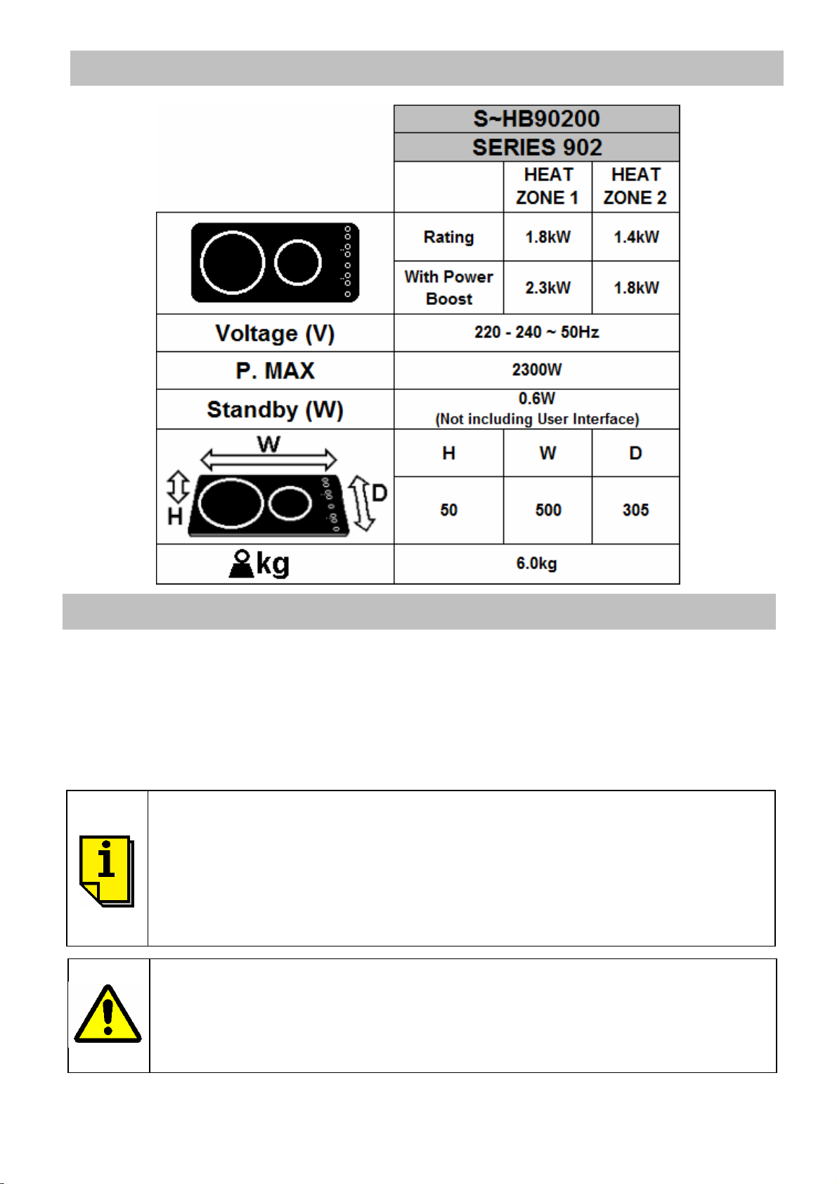
SPECIFICATION
•
•
Note: Items 6, 7 & 8 are recommended options, read installation section for details.
INTRODUCTION
This appliance must be installed in accordance with the relevant local and national regulations
in force. Failure to instal the appliance correctly could invalidate any warranty or liability claims
and lead to prosecution. Installation should only be carried out by a qualified installer or
engineer. Please refer to the methods of installation and use within this handbook.
Our policy is one of continuous development and improvement. Specifications and illustrations
may change subsequent to publication.
This appliance is not intended for use by persons (including
children) with reduced physical, sensory or mental capabilities, or
lack of experience and knowledge, unless they have been given
supervision or instruction concerning use of the appliance by a
person responsible for their safety.
• Children should be supervised to ensure that they do not play with
the appliance.
If the glass surface is cracked, switch off the appliance to avoid the
possibility of electric shock.
• Metal objects such as knives, forks, spoons and lids should not be
placed on the hob surface since they can get hot.
• Condensation on electronics during storage must be avoided
3
Page 4

OPERATION
Cooking on Induction
Cooking with an Induction Hob is different to a conventional hob which has either heating
elements or hotplates. An induction hob uses powerful electro magnets which are located below
the glass surface. When a pan manufactured from magnetic material, is placed directly above
an electro-magnet, energy is induced into the metal of the pan. This energy causes the metal
pan to become hot and is sufficient to provide the heat for cooking. Since heat for cooking is
created inside the pan, only the area of glass in direct contact with the pan will become hot.
To ensure you achieve maximum cooking efficiency from your Induction hob we recommend the
use of pans which are specifically made for this type of appliance. A good guide is to choose
pans which bear the symbol ‘Class Induction’. If however you wish to use your existing pans
and are unsure if they are suitable you can check if they are the correct type by using a magnet.
If the magnet will attach to the base then the pan is suitable for induction. Please ensure,
regardless of pan type (stainless, enamelled steel, cast iron, etc) the pan base is smooth and
flat to avoid the risk of scatching the glass. Never slide the pan across the glass surface.
We recommend the following pan sizes for each Heat Zone: Heat Zone 1 – Ø135mm to Ø220mm
Heat Zone 2 – Ø90mm to Ø160mm
Glass, ceramic or earthenware pans, aluminium (unless they have a special
base), copper pans and some non-magnetic stainless steel pans are not suitable
for use on Induction hobs.
Using the Hob
Each heating zone on the hob can be controlled individually using the touch controls.
Illuminated displays for both zones provide information on power settings, timer function,
pause/resume, power boost, etc. The following chart provides information on how to operate
and choose the various functions available.
Induction Hob control panel
I< Heat Zone 1 >I I< Heat Zone 2 >I
Touch Controls L.E.D Display
When operating the Induction Hob it is not necessary to apply pressure to the
touch controls, only a gentle touch is required. The appliance emits a beep and
the illuminated display informs of your action.
4
Page 5

Operation/Function Touch Controls L.E.D. Display
1. Ensure the power supply is connected and turned on
2. Switch On:
If no function activated
Touch the Power On/Off
symbol until it beeps.
after 10seconds system
will switch to standby.
3. Heat setting For each zone, touch the
symbols to select required
heat.
The heat setting is
adjustable during cooking
by touching either symbol.
4. Pan detection
The display for each heat zone
will illuminate as shown.
The heat setting is adjustable
between 1 & 12 for each zone.
Either heat zone will only function
with a pan in place. When pan
removed or not present the
display flashes & shows the
following symbol.
5. Switch Off zone heating
With both Heat Zones
switched Off, system is in
standby mode.
6. Switch Off Induction Hob.
To Switch Off completely
turn off power supply.
7. Pause/Resume
Pause function only
operates for a period of
10minutes. After this period
system automatically goes
to standby.
For each zone, touch
symbol until ‘0’
appears on the display or
touch and hold both
symbols.
Touch the Power On/Off
symbol until it beeps.
To Pause touch
until it beeps.
To Resume touch
until it beeps and
then touch any other
symbol to resume cooking
on previous heat setting.
When the zone is switched Off
the display will illuminate as
shown
Illuminated display is blank.
Both zones are paused and their
displays illuminate as shown.
5
Page 6

Operation/Function Touch Controls L.E.D. Display
8. Simmer Control
Available on either zone, a
constant very low heat
65oC suitable for melting
chocolate or delicate
sauces.
9. Power boost
Limited to 10minutes on
either heat zone, but not
simultaneously. Selecting
boost on large heat zone,
small zone automatically
turned off.
Selecting boost on small
zone with large zone set
greater than 8, setting will
automatically reduced to 8.
10. Timer function
Available on either heat
zone, maximum of
99minutes. Timer can be
used without setting zone
heating.
Touch and hold
symbol until ‘Lo’
displayed.
To deactivate touch either
Touch and hold
symbol until ‘12’
displayed. Touch again
until ‘P’ displayed.
To deactivate power boost
touch
symbol.
Set the heat zone to the
desired heat using
Activate timer by touching
symbol. A neon in
the display will flash to
indicate timer function
selected. Select the
desired time (from 1 to 99)
When selected the display
illuminates as shown.
When boost selected the display
illuminates as shown.
When timer function selected the
display shows duration in
minutes and neon lit in top of
display
11. Hot hob surface
using
Timer starts countdown
immediately and beeps at
the end of cooking time.
Heat zone switches Off.
After using either zone an
‘H’ will illuminate in the
display to indicate surface
may be hot to the touch.
Take care when above
illuminated on display, surfaces
will be above 60oC.
After use
1. Switch Off the hob element by its control.
2. Turn Off the power supply
6
Page 7

OPERATION
Persons fitted with pacemakers or other electrical implants
•
settings. Remove spills immediately and keep area clean.
Do’s and Don’ts
DO Read the instructions carefully before using the appliance.
DO Clean the appliance regularly
DO Remove spills as soon as they occur
DO Check controls are in the OFF position when finished
DO Use the correct type pans and always lift the pan, sliding may cause scratches.
DO NOT Allow children near the appliance when in use. Turn pan handles away from the
front so that they cannot be caught accidentally.
DO NOT Use steam cleaners or other types of power cleaners.
DO NOT Use abrasive cleaners, wire wool, bleaches, stain removers or any implement
which will damage the glass.
DO NOT Use kitchen foil on the hob.
DO NOT Heat sealed tins of food, they may explode.
DO NOT Leave empty pans on a heat zone.
This Induction Hob complies with the applicable standards on
electromagnetic interference and complies fully with the European
Directive 89/336/EEC. It should not interfere with other electrical equipment
providing they also comply to the regulations.
Persons who have a heart pacemaker or other electrical implant should
clarify with their doctor or the producer of the implant, whether those units
comply with the regulations.
CARE & MAINTENANCE
Before using the hob for the first time, check the power supply is switched off, use a dampened
paper towel or clean cloth to remove any soiling or residual factory lubricants. Once clean apply
a thin coating of cleaner conditioner to the glass surface and polish with a clean cloth.
The conditioner provides a protective surface coating which will make cleaning the hob easier.
Occasional reapplying of the conditioner will prevent the accumulation of deposits from cooking.
If the glass surface becomes discoloured due to cooking deposits, clean the glass using a mild
cream cleaner or use a ceramic hob scraper. Wipe the surface clean and re-apply the cleaner
conditioner.
The appliance has automatic overheat protection which if activated
may limit functions or completely turn Off the hob.
• Spillage over the touch controls on the glass can activate change in
7
Page 8

INSTALLATION
Regulations & Standards
This appliance must be installed in accordance with the relevant local and national regulations
in force. Installation should only be carried out by a qualified installer or engineer.
The appliance is suitable for installation into Holiday Homes, Touring Caravans and Boats. In all
cases the national standards with regard to appliance location and ventilation for the particular
vehicle into which the appliance is to be installed must be adhered to.
Position
A cutout should be prepared in the worktop as shown on page 2. A gap between the edge of the
hotplate and combustible material, unless protected by a layer of non-combustible material,
must exist, the minimum size of this gap for the required installation is shown below:-
A = 40mm, minimum direct distance between hotplate edge and rear wall.
B = 100mm, minimum direct distance between hotplate edge and side wall.
Cupboards above the appliance must be positioned a minimum of 500mm from the glass
surface.
A foam seal is supplied which must be attached to the underside of the appliance around its
periphery prior to positioning the hob on the worktop. The appliance should then be clamped in
position using the 4 clamping screws provided.
The underside of the appliance must be shielded. It is recommended the shield is manufactured
from non-combustible material and located a minimum of 25mm below the lowest part of the
appliance. This air space must be provided with ventilation and we recommend ventilation slots,
minimum 3000mm2, located in one of the 3 positions (6, 7 or 8) as shown in the diagram on
page 2. If the appliance is to be located over a cupboard or drawer the ventilation slots may be
positioned in the base of the enclosure at the rear.
8
Page 9

•
INSTALLATION
Electrical Connection
Models fitted with power cord only
This appliance is supplied with a double insulated cord, type 227 IEC 53, HO5V V-F, which is
suitable for use up to 4 amps. This should be connected to a double pole switched mains
supply, with 3mm minimum contact separation at all poles. Ensure that all electrical cables and
wires are routed well clear of any heat source, including this appliance. Do not allow the cord to
hang loose into the lower compartment. The switch must be accessible after installation.
Models fitted with Euro plug and power cord
This appliance is supplied with a Euro plug attached to the end of the power cord, for
connection to a switched wall mounted socket. After connection ensure the power cord and any
other electrical wires are routed well clear of any heat source, including this appliance. Do not
allow the cord to hang loose into the lower compartment. The switched socket must be
accessible after installation.
If the power cord is damaged, it must be replaced by the manufacturer, its
service agent or similarly qualified persons in order to avoid a hazard.
SERVICING
All servicing must be carried out by an approved competent person. After service the appliance
must be checked for electrical safety.
If servicing requires removal of the appliance:-
(1) Switch off power supply and disconnect appliance from 240V supply.
(2) Release and remove the appliance clamping screws.
(3) Carefully lift out the appliance from the worktop and place on a suitable surface.
This appliance is not intended to be operated by means of an
external timer or separate remote control system.
• The appliance must not be modified or adjusted unless carried out
by the manufacturer or his representative. No parts other than those
supplied by the manufacturer should be used on this appliance.
9
 Loading...