


TM
1
7
2
5
I
I
2
G
D
E
x
d
b
e
b
I
I
C
T
5
-
T
6
,
E
x
t
b
I
I
I
C
T
1
0
0
°
C
-
T
8
5
°
C
,
F
M
1
0
A
T
E
X
0
0
5
8
X
I
E
C
E
x
F
M
G
1
0
.
0
0
2
2
X
E
x
d
b
e
b
I
I
C
T
5
-
T
6
,
E
x
t
b
I
I
I
C
T
1
0
0
°
C
-
T
8
5
°
C
PN 27656
T
e
r
m
i
n
a
t
o
r
Z
T
F
o
r
u
s
e
a
s
a
n
a
d
j
u
s
t
a
b
l
e
c
o
n
t
r
o
l
/
l
i
m
i
t
e
r
t
h
e
r
m
o
s
t
a
t
I
P
6
6
-
6
0
°
C
≤
T
a
≤
+
5
0
°
C
T
5
,
1
0
0
°
C
;
-
6
0
°
C
≤
T
a
≤
+
4
0
°
C
T
6
,
8
5
°
C
Terminator
ZT-MI-WP
Thermostat Connection Kit
INSTALLATION PROCEDURES
For Thermostat Connection (1-2 Heating Cables) Applications
For Use With MI Mineral Insulated Heating Cable Sets
TerminatorTM ZT-MI-WP INSTALLATION PROCEDURES
T
e
r
m
i
n
a
t
o
r
Z
T
IP66
-45
°
C
Ta
+
55
°
C
F
o
r
u
s
e
a
s
a
n
a
d
j
u
s
t
a
b
l
e
c
o
n
t
r
o
l
t
h
e
r
m
o
s
t
a
t
w
i
t
h
T
h
e
r
m
o
n
h
e
a
t
i
n
g
c
a
b
l
e
s
y
s
t
e
m
s
II 2 G & D EEx ed II C T5
0539
DEMKO 02ATEX132552X
1
7
2
5
I
I
2
G
D
E
x
d
b
e
b
I
I
C
T
5
-
T
6
,
E
x
t
b
I
I
I
C
T
1
0
0
°
C
-
T
8
5
°
C
,
F
M
1
0
A
T
E
X
0
0
5
8
X
I
E
C
E
x
F
M
G
1
0
.
0
0
2
2
X
E
x
d
b
e
b
I
I
C
T
5
-
T
6
,
E
x
t
b
I
I
I
C
T
1
0
0
°
C
-
T
8
5
°
C
PN 27656
T
e
r
m
i
n
a
t
o
r
Z
T
F
o
r
u
s
e
a
s
a
n
a
d
j
u
s
t
a
b
l
e
c
o
n
t
r
o
l
/
l
i
m
i
t
e
r
t
h
e
r
m
o
s
t
a
t
I
P
6
6
-
6
0
°
C
≤
T
a
≤
+
5
0
°
C
T
5
,
1
0
0
°
C
;
-
6
0
°
C
≤
T
a
≤
+
4
0
°
C
T
6
,
8
5
°
C
The following installation procedures are suggested guidelines
for the installation of the Terminator ZT-MI-WP Kit.
Receiving, Storing and Handling . . .
1. Inspect materials for damage incurred during shipping.
2. Report damages to the carrier for settlement.
3. Identify parts against the packing list to ensure the proper
type and quantity has been received.
4. Store in dry location.
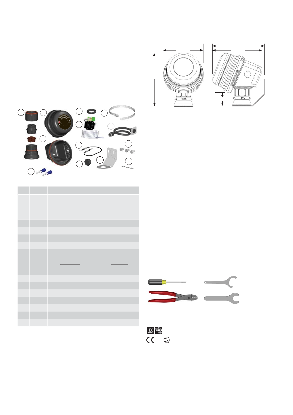
Kit Contents . . .
1
2
3
13
Wire Pins (per MI cable cold lead,order separately)
4
6
8
9
10
5
7
11
12
Dimensions . . .
205mm
155mm
190mm
206mm
50mm
Warnings . . .
• Due to the risk of electrical shock, arcing and fi re caused
by product damage or improper usage, installation or
maintenance, a ground-fault protection device is required.
• Installation must comply with Thermon requirements
(including form PN 50273U for Ex systems) and be installed
in accordance with the regulations as per the norm EN IEC
60079-14 for hazardous areas (where applicable), or any
other applicable national and local codes.
• Component approvals and performance ratings are based
on the use of Thermon specifi ed parts only.
Item Quantity Description
Expediter Assembly
Support Cap with O-Ring
11
Threaded Grommet Compressor
Grommet
Support Base with O-Ring
2 1 Junction Box Lid
3 1 Junction Box Base with O-Ring and M25 Dust Cap
4 1 Nut
5 1 Banding
Thermostat w/ Terminal Blocks
61
(Refer to terminal specifi cations for maximum allowable wire size)
Thermostat Type Control Range
ZT-C-300 0
ZT-C-500 20°C to +500°C
°C to +300°C
7 1 Capillary Armouring w/ Glands
8 1 Junction Box Cord
9 2 Blind Plug M20
10 1 Bracket
11 3 Screws
12 3 Washers
13 4 Wire Pins
• De-energize all power sources before opening enclosure.
• Avoid electrostatic charge. Clean only with a damp cloth.
• Keep ends of heating cable and kit components dry before
and during installation.
• Minimum bending radius of heating cable is 6 times the cable
outer diameter.
• Individuals installing these products are responsible for
complying with all applicable safety and health guidelines.
Proper Personal Protective Equipment (PPE) should be
utilized during installation. Contact Thermon if you have any
additional questions.
Tools Required . . .
3 mm
8 mm
Terminator-LN-Tool
(order separately)
28 mm
33 mm
Certifi cations/Approvals . . .
IP66 -60°C Ta +50°C T5, 100°C; -60°C Ta +40°C T6, 85°C
Ordinary & Hazardous Locations
FMG 10.0022X Ex db eb IIC T5-T6, Ex tb IIIC T100°C-T85°C
1725 II 2 GD Ex db eb IIC T5-T6, Ex tb IIIC T100°C-T85°C FM 10ATEX0058X
2
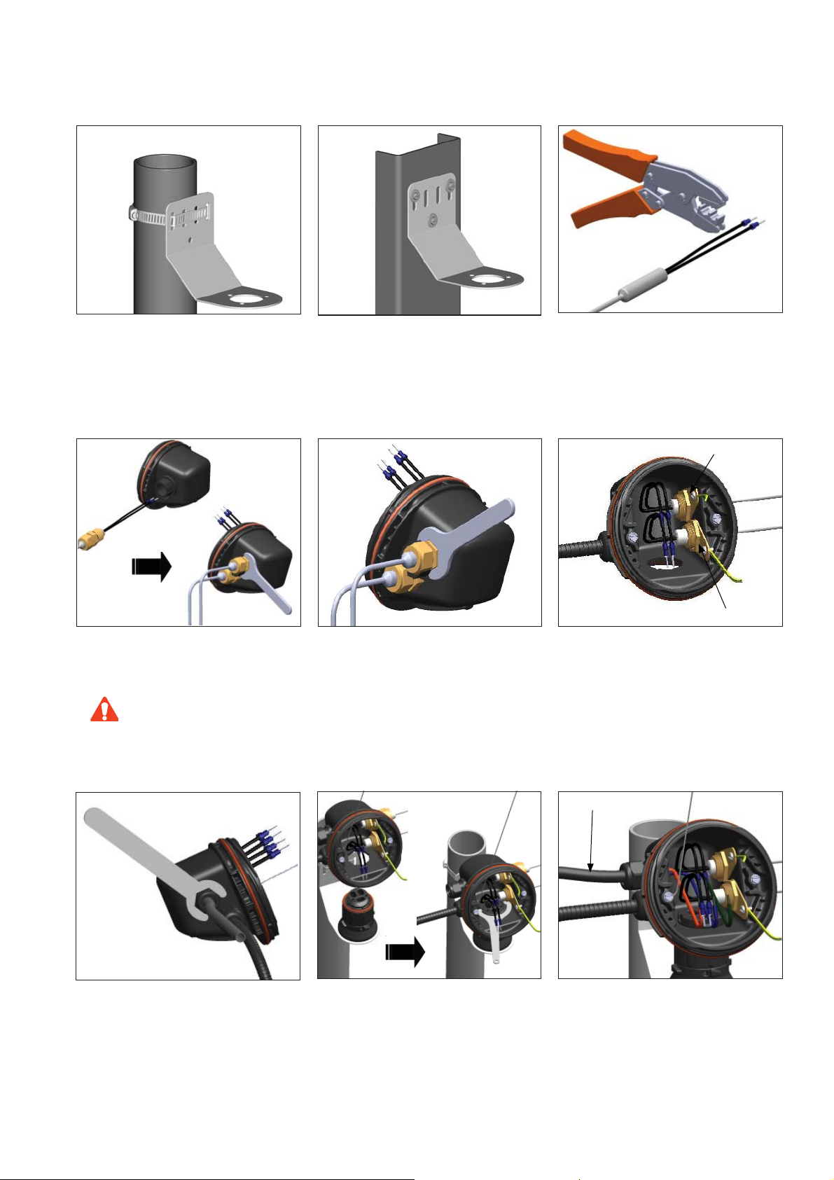
TerminatorTM ZT-MI-WP INSTALLATION PROCEDURES
1a. Mounting Method 1: Secure wall mount
bracket to mounting surface using pipe band
provided with kits.
3. Route MI cable cold leads through M20
threaded entries. Screw cable glands into
junction box.
Do not overtighten to ensure o-ring
CAUTION
is not damaged during installation.
1b. Mounting Method 2: Secure wall mount
bracket to mounting surface using customer
supplied screws, fl at washers, and nuts.
4. Center cold lead sleeve inside cable gland.
Tighten cable glands until ferrule begins to
make contact with cold lead sleeve and cold
lead sleeve cannot be moved by hand. Tighten
cable gland 1/8 additional turn or to a torque
value of 16 Nm (142 lb-in).
2. Crimp appropriate wire pins (2.5 mm
mm2) on MI cable cold lead wires.
Earth Tag and Lock Nut
Earth Tag and Lock Nut
2
or 6
5. Install user supplied M20 Earth Tag and Lock
Nut to threaded M20 Gland.
6. Remove M25 dust cap. Install M25 power
gland (customer supplied) in M25 threaded
entry.
7. Mount junction box base on expediter. Make
sure to align slots to properly orient junction
box base. Tighten nut with Terminator-LNTool. If mounting horizontally, threaded gland
holes must face downward.
3
Power Cable
8. Install power cable (if necessary).
TerminatorTM ZT-MI-WP INSTALLATION PROCEDURES
1
7
2
5
I
I
2
G
D
E
x
d
b
e
b
I
I
C
T
5
-
T
6
,
E
x
t
b
I
I
I
C
T
1
0
0
°
C
-
T
8
5
°
C
,
F
M
1
0
A
T
E
X
0
0
5
8
X
I
E
C
E
x
F
M
G
1
0
.
0
0
2
2
X
E
x
d
b
e
b
I
I
C
T
5
-
T
6
,
E
x
t
b
I
I
I
C
T
1
0
0
°
C
-
T
8
5
°
C
PN 27
6
56
T
e
r
m
i
n
a
t
o
r
Z
T
F
o
r
u
s
e
a
s
a
n
a
d
j
u
s
t
a
b
l
e
c
o
n
t
r
o
l
/
l
i
m
i
t
e
r
t
h
e
r
m
o
s
t
a
t
I
P
6
6
-
6
0
°
C
≤
T
a
≤
+
5
0
°
C
T
5
,
1
0
0
°
C
;
-
6
0
°
C
≤
T
a
≤
+
4
0
°
C
T
6
,
8
5
°
C
1
7
2
5
I
I
2
G
D
E
x
d
b
e
b
I
I
C
T
5
-
T
6
,
E
x
t
b
I
I
I
C
T
1
0
0
°
C
-
T
8
5
°
C
,
F
M
1
0
A
T
E
X
0
0
5
8
X
I
E
C
E
x
F
M
G
1
0
.
0
0
2
2
X
E
x
d
b
e
b
I
I
C
T
5
-
T
6
,
E
x
t
b
I
I
I
C
T
1
0
0
°
C
-
T
8
5
°
C
PN 27
65
6
T
e
r
m
i
n
a
t
o
r
Z
T
F
o
r
u
s
e
a
s
a
n
a
d
j
u
s
t
a
b
l
e
c
o
n
t
r
o
l
/
l
i
m
i
t
e
r
t
h
e
r
m
o
s
t
a
t
I
P
6
6
-
6
0
°
C
≤
T
a
≤
+
5
0
°
C
T
5
,
1
0
0
°
C
;
-
6
0
°
C
≤
T
a
≤
+
4
0
°
C
T
6
,
8
5
°
C
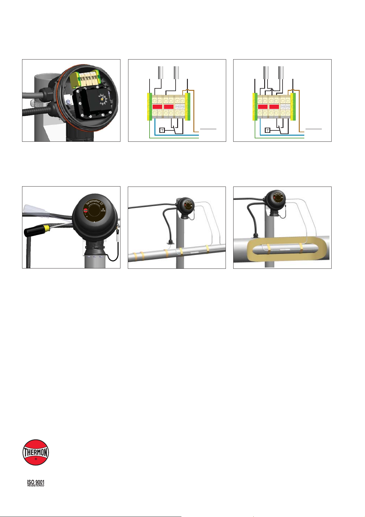
9. Install thermostat and complete system wiring.
Terminal set screws shall be tightened to a
torque value of 1.4 Nm (12.4 lb-in). See wiring
diagrams for details. Set thermostat at desired
setpoint.
a
t
n
o
i
r
o
c
m
n
e
l
t
r
b
o
a
l
t
/
s
l
i
u
m
j
Z
d
i
r
t
a
e
r
n
t
a
h
s
T
e
e
a
r
m
e
s
o
T
u
s
t
r
a
o
t
F
PN 27656
1
7
X
C
8
°
5
I
P
6
2
5
5
0
8
C
0
T
°
-
6
X
5
C
E
8
-
°
T
6
,
0
A
0
6
0
0
°
T
C
1
1
T
C
≤
°
M
0
C
T
F
I
I
4
a
I
I
,
+
I
≤
2
C
°
≤
b
+
G
5
t
a
5
T
D
8
0
I
x
°
T
E
≤
C
-
E
E
C
C
T
°
C
5
x
,
0
°
,
6
E
-
1
;
0
0
C
°
0
d
6
x
b
0
T
-
1
e
F
T
b
5
M
C
I
I
T
I
I
C
I
G
T
b
5
t
-
C
x
T
E
6
,
I
1
I
0
b
.
0
e
0
b
2
d
2
x
X
E
Heat Trace #1 Heat Trace #2
224
N
N
Wiring Details: Single Core
Heat Trace #1 Heat Trace #2
Earth TagEarth Tag Earth Tag Earth Tag
224
N
L1
PEPE
Power Supply
L1
N
PE
N
L1
PEPE
Power Supply
L1
N
PE
Wiring Details: Dual Core
10. Install junction box lid and twist hand tight.
Insert screwdriver into ratchet slots located
on side of junction box base. Use screwdriver
to ratchet on junction box lid. Lid will rotate
30 degrees. To remove lid, repeat steps in the
opposite direction.
THERMON . . . The Heat Tracing Specialists
www.thermon.com
11. Fix thermostat bulb and capillary tube to pipe.
®
12. Seal penetration through insulation cladding.
European Headquarters
Boezemweg 25 • PO Box 205
2640 AE Pijnacker • The Netherlands
Phone: +31 (0) 15-36 15 370
Corporate Headquarters
100 Thermon Dr.
PO Box 609
•
San Marcos, TX 78667-0609 • USA
Phone: +1 512-396-5801
For the Thermon offi ce nearest you
visit us at . . .
www.thermon.com
Specifi cations and information are subject to change without notice. Form PN50855U-0113
 Loading...