


HT Heating Module
INSTALLATION PROCEDURES
HT Heating Module INSTALLATION PROCEDURES
Receiving, Storing and Handling . . .
1. Inspect materials for damage incurred during shipping.
2. Report damages to the carrier for settlement.
3. Identify parts against the packing list to ensure the proper
type and quantity has been received.
4. Store in a dry indoor location.
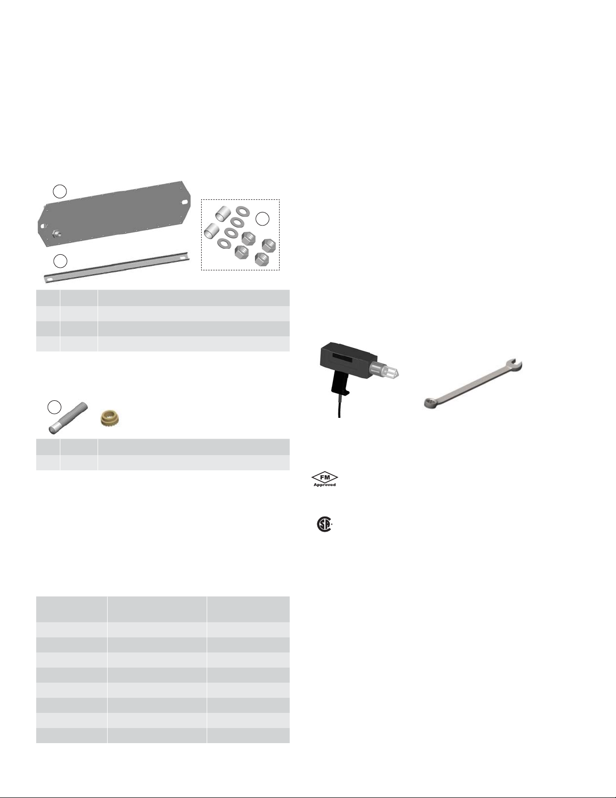
Contents . . .
1
3
2
Item Quantity Description
1 1 Heating Module
2 1 Reinforcing Channel
3 1 Spacer Kit
Warnings . . .
• Multiple modules can be energized from the same circuit
breaker based on operating voltage and current draw. The
current draw and/or breaker sizing should be based on the
National Electrical Code, Canadian Electrical Code or any other
applicable code.
• To minimize the potential for arcing and ground-fault protection.
The National Electrical Code (NEC) and Canadian Electrical
Code (CEC) require ground-fault protection of equipment for
each branch circuit supplying electric heat tracing.
• Component approvals and performance ratings are based on
the use of Thermon specifi ed parts only.
• De-energize all power sources before connecting heaters.
• Individuals installing these products are responsible for
complying with all applicable safety and health guidelines.
Proper Personal Protective Equipment (PPE) should be utilized
during installation. Contact Thermon if you have any additional
questions.
Tools Required . . .
Mounting Studs:
(Order Separately for each Heating Module to be fabricated.)
4
Item Quantity Description
4 2 1/2" Stud with Ferrule
Standard Mounting Equipment . . .
Each HT Heating Module is shipped with a reinforcing channel,
spacers, 1/2" nuts and 1/2" washers. Mounting studs and
installation templates are supplied separately to facilitate
marking heater and mounting stud locations prior to installation
of heaters.
Available HT Module Sizes1 . . .
Catalog Number
Base Module
612 6 x 16.1 (15 x 40) 14.1 (36)
624 6 x 27.6 (15 x 70) 25.6 (65)
636
648 6 x 50.6 (15 x 129) 48.6 (123)
212 12 x 16.1 (30 x 40) 14.1 (36)
224 12 x 27.6 (30 x 70) 25.6 (65)
236
248 12 x 50.6 (30 x 129) 48.6 (123)
Module Dimensions
in (cm)
6 x 39.1 (15 x 99) 37.1 (94)
12 x 39.1 (30 x 99) 37.1 (94)
Stud Spacing
in (cm)
Stud Welder
19mm (0.75") Wrench
Certifi cations/Approvals . . .
Factory Mutual Research
Ordinary Locations
Hazardous (Classifi ed) Locations
Class II, Division 2, Groups F & G
Canadian Standards Association
Ordinary Locations
Hazardous (Classifi ed) Locations
Class II, Division 2, Groups E, F, & G
Notes:
1. Catalog numbers shown are partial numbers. Delivered product
will have prefi x and suffi x designations to identify complete
catalog number. Contact Thermon for design assistance.
2

HT Heating Module INSTALLATION PROCEDURES
Stud
Spacer
Installation Template
1. Have template and heating system layout
drawing available. Select the correct sized
template. Position installation template on
hopper wall per layout drawing and mark stud
locations. If two or more modules are to be
placed in one area, care should be taken to
insure proper fi t of all modules. By marking the
outline of each template with chalk or crayon
on the hopper wall, clearances can be verifi ed
prior to welding of studs.
Reinforcing Channel
Washer
Nuts
Washer
Stud Welder
(By Others)
2. Weld studs in place per the manufacturer's
recommendations.
Notes:
• Sandblasting of hopper surface or grinding
of welding beads or weld splatter is NOT
required for proper installation of the
HT Heating Modules. However, to provide
maximum heat transfer effi ciency, it is
recommended to install the HT Heating
Module on a fairly clean, smooth surface.
L1
L2/N
HT Heating Module
3. Place spacer on each stud and then place HT
Heating Module over studs.
2" Minimum Air Space
Heating Insulation
Heating Module
4. Assemble mounting components (supplied
with each module) in the following order:
• Place reinforcing channel over module and
studs.
• Place washer on each stud.
• Secure with one nut per stud and torque
down with 20-30 foot pounds.
• Add second nut to each stud and tighten.
Carefully route lead wires to junction box and
connect to the terminal strip according to the
layout drawing. See typical wiring schematic.
Typical Wiring Schematic for Heating Modules
IMPORTANT:
See Thermon project specifi c heater layout
and wiring drawings for actual heater wiring.
Hopper Insulation Design
IMPORTANT: The design of the hopper heating
system is based on the transfer of heat into the
hoppers via convection and conduction in the
air spaces between each stiffener to provide an
“oven” effect to ensure even distribution of heat.
It is important that the insulation be properly
sealed at each stiffener level to prevent drafts
or chimney effects. Allow 2 inch minimum
air space for heaters. (See project installation
manual for additional details).
Notes:
1. Route lead wires to junction box(es) according to project specifi c heater layout drawing. CAUTION: Do not rotate the feed through
fi tting which supports the heater wiring.
2. During heater installation, heaters should not be left exposed to rain, snow, moisture, etc..
3. Electrical insulation resistance test (megger) and resistance (Ohms) should be done on each heater per project installation manual.
3

THERMON . . . The Heat Tracing Specialists
®
100 Thermon Dr. • PO Box 609 • San Marcos, TX 78667-0609
Phone: 512-396-5801 • Facsimile: 512-396-3627 • 1-800-820-HEAT
www.thermon.com In Canada call 1-800-563-8461
Specifi cations and information are subject to change without notice. Form 50862-0712
For the Thermon offi ce nearest you
visit us at . . .
www.thermon.com
 Loading...