


TM
FLX
Self-Regulating
Winterization/Freeze Protection
INSTALLATION PROCEDURES
FLX
TM
Self-Regulating
INSTALLATION PROCEDURES
Refer to the “FLX Cable Testing Report” for required recording
of test data and circuit information.
Upon Receiving Cable . . .
1. Upon receiving heating cable, check to make sure the proper
type and output have been received. All cables are printed
on the outer jacket with part number, voltage rating and watt
output.
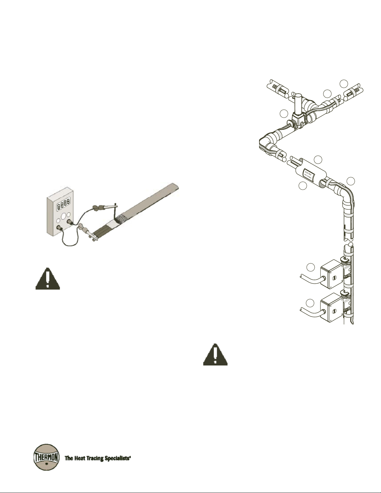
2. Visually inspect cable for any damage incurred during shipment. The heating cable should be tested to ensure electrical integrity with at least a 500 Vdc megohmmeter (megger) between the heating cable bus wires and the heating
cable metallic braid. IEEE 515.1 recommends that the test
voltage for polymer insulated heating cables be 2500 Vdc.
Minimum resistance should be 20 megohms. (Record 1 on
Cable Testing Report.)
Typical Heat Tracing Installation . . .
A complete electric heat tracing system will typically include
the following components:
1. Electric heat tracing
cable.
2. Power connection kit.
3. Control thermostat (may
be remote ambient sensing control.)
4. In-line/T-splice
kit (permits two
or three cables to
be spliced together).
5. Cable end termination.
6. Attachment tape (use on 12”
intervals or as required by code
or specification).
7. “Electric Heat Tracing” label (peel-and-stick
label attaches to insulation vapor barrier
on 10’ intervals or as required by code or
specification).
4
7
8
5
6
1
Connect the positive lead of the megger to the cable bus
wires and the negative lead to the metallic braid.
CAUTION: DO NOT connect power to heating
cable while it is on reel or in shipping carton.
Before Installing Cable . . .
1. Be sure all piping and equipment to be traced is completely
installed and pressure tested.
2. Surface areas where heat tracing is to be installed must be
reasonably clean. Remove dirt, rust and scale with a wire
brush and oil and grease films with a suitable solvent.
8. Thermal insulation and vapor barrier
(by others).
The absence of any of these items
can cause a system to malfunction or
represent a safety hazard.
The National Electric Code and Canadian Electrical
Code require ground-fault protection be provided
for all electric heat tracing.
3
2
1
FLX
Self-Regulating
Initial Installation . . .
TM
1. Begin temporary installation at the proposed end-of-circuit
location and lay out heating circuit on the pipe, allowing extra cable for the power connection and for any splice locations. Refer to illustration below for temporary installation.
Temporary Installation
Proposed Power
Connection Location
Cable Allowance for
In-Line Heat Sinks
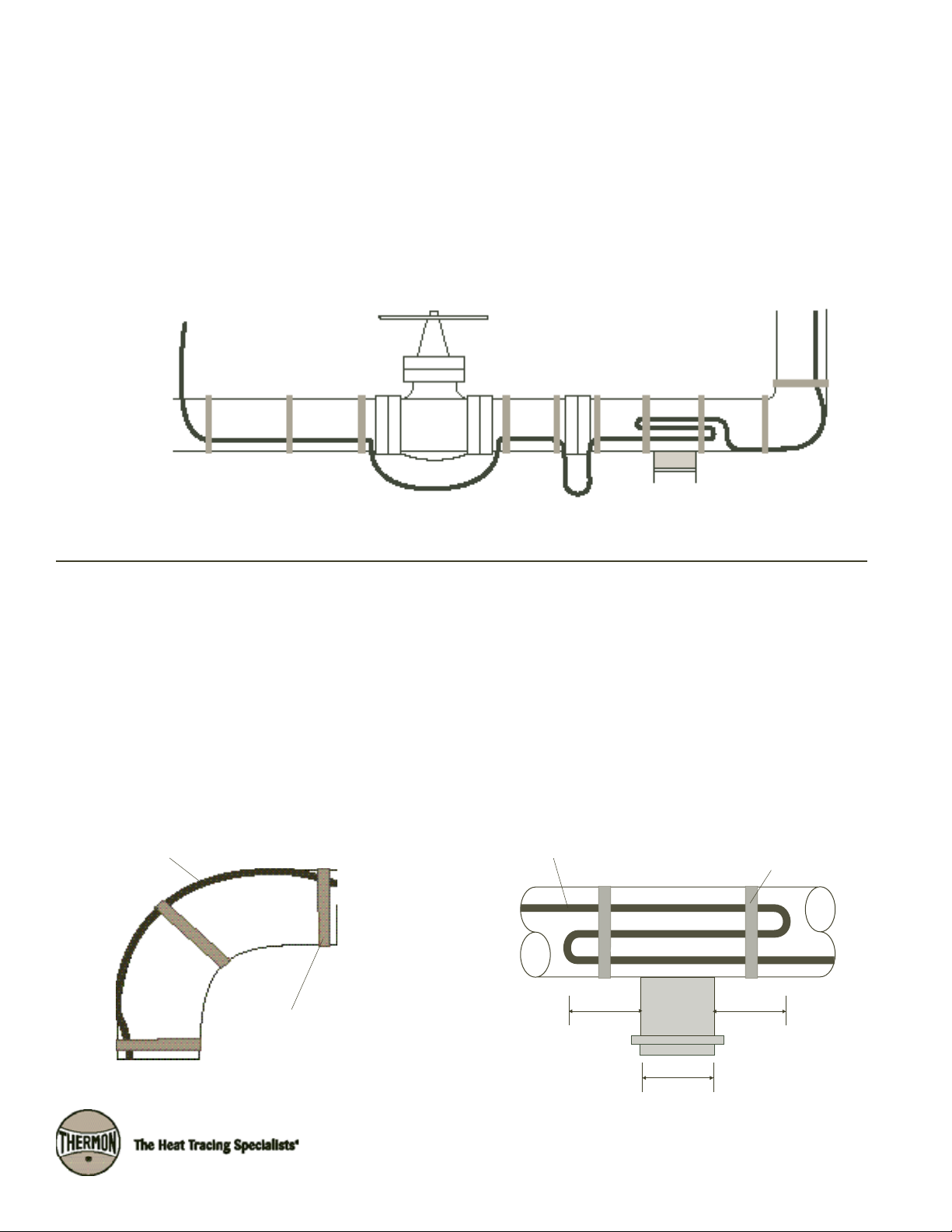
Installation on Fittings and Equipment . . .
2. Make heating cable allowances for valves, flanges, elbows
and supports as per the applicable drawings and table on
pages 2 and 3 of these installation procedures. See product
specifications sheet for heating cable minimum bend radius.
Proposed End-of-Circuit
Location
Pipe Support
1. Install heating cable in accordance with illustrations below.
Secure heating cable to piping using attachment tape.
2. Elbows: Locate the cable on the outside radius of an elbow
to provide sufficient heat to compensate for the added pip-
3. Pipe Supports: Insulated pipe supports require no additional
heating cable. For uninsulated supports, allow two times the
length of the pipe support plus an additional 15” (40 cm) of
heating cable.
ing material. Secure the cable to the pipe on each side of
the elbow with attachment tape.
Pipe Elbow Pipe Support
Heating Cable
Attachment Tape
(Typical)
Heating Cable
3” Min.
(8 cm)
Attachment Tape
(Typical)
3” Min.
(8 cm)
Support
Length
2

INSTALLATION PROCEDURES
4. Flanges: Allow cable to be looped around pipe on each side
of and adjacent to the flange. Heating cable must maintain
contact with flange when bending around pipe flanges to
compensate for additional heat loss.
Typical Flange Detail
Heating Cable
12” Max.
Note:
Flange allowance will vary based on method of insulating flange and adjacent piping.
(30 cm)
Attachment Tape
(Typical)
5. Additional cable is required to provide extra heat at valves,
pumps and miscellaneous equipment to offset the increased heat loss associated with these items. Refer to
Table 1 for estimated cable requirements for installation on
typical valves and pumps.
6. Install heating cable on valves and pumps utilizing a looping
technique (this allows the valve or pump to be removed if
required).
Typical Valve Details
Heating Cable
Temporary Loop of Cable on Valve
Attachment Tape
(Typical)
Table 1: Valve and Pump Allowances
Pipe
Size
½" 6" 1' 0 1' 2'
¾" 9" 1'-6" 0 1'-6" 3'
1" 1' 2' 1' 2' 4'
1¼" 1'-6" 2' 1' 3' 4'-6"
1½" 1'-6" 2'-6" 1'-6" 3' 5'
2" 2' 2'-6" 2' 4' 5'-6"
3" 2'-6" 3'-6" 2'-6" 5' 7'
4" 4' 5' 3' 8' 10'
6" 7' 8' 3'-6" 14' 16'
8" 9'-6" 11' 4' 19' 22'
10" 12'-6" 14' 4' 25' 28'
12" 15' 16'-6" 5' 30' 33'
14" 18' 19'-6" 5'-6" 36' 39'
16" 21'-6" 23' 6' 43' 46'
18" 25'-6" 27' 6'-6" 51' 54'
20" 28'-6" 30' 7' 57' 60'
24" 34' 36' 8' 68' 72'
30" 40' 42' 10' 80' 84'
Screwed Flanged Welded
Valve Type
Pump Type
Screwed Flanged
Heating Cable Attachment Tape
Heating Cable Serpentined on Valve
(Typical)
Typical Pump Detail
Heating Cable
Heating Cable Serpentined on Pump
Attachment Tape
(Typical)
3

FLX
TM
Self-Regulating
Completing the Installation . . .
1. Begin final cable attachment by securing the end-of-circuit
termination kit and working back toward the power supply.
•Flexibleheatingcablesaretobeinstalledusingattachment
tape. Circumferential bands of tape should be installed at
12” (30 cm) intervals to keep the cable in proper contact
with the pipe. Refer to Table 2 below to calculate the number of rolls of attachment tape required based on the pipe
diameter 1.
•Ifapplicable,refertoinstallationdetailsprovidedwiththe
project drawings or contact Thermon for additional information regarding installation.
2. In addition to the circumferential tape requirements, a
continuous covering of aluminum foil tape may be required
when:
•Sprayorfoamurethane2 thermal insulation is applied.
•Heattracingnonmetallicpiping.
•Designrequirementsdictatetheuseofaluminumtapeto
improve heat transfer.
3. Complete splice connections (if required) in accordance
with the installation instructions provided with the splice kit.
4. Install power connection kit in accordance to the detailed
installation instructions provided with the kit.
5. Before making power connections, repeat the megger test
with at least a 500 Vdc megohmmeter (megger) between
the heating cable bus wires and the heating cable metallic
braid. IEEE 515.1 recommends that the test voltage for
polymer insulated heating cables be 2500 Vdc. The minimum acceptable level for the megger reading for any
polymer-insulated heat tracing cable is 20 megohms.
(Record 2 on Cable Testing Report)
Temperature Control . . .
1.
When a line sensing controller is specified, the sensor should
be placed at least 90° around the circumference from the
heating cable, or at least 2" (5 cm) from the cable.
Heating Cable vs. Sensor Location
Optional Second
Heating Cable
Temperature
Sensor
90°
2. For pipewall sensing thermostatic control, the heating circuit
is to be connected in series with the control contacts as
shown in illustration below. The pipewall sensing thermostat
may require more than one support point.
Pipewall Sensing Control Connection
L1
L2/N
Power Connection
Temperature Sensor End Termination
Heating Cable
3. When using an ambient sensing temperature controller, the
mounting location should be representative of the coldest
region, and the sensing element should not be exposed to
direct sunlight or any additional heat source.
Ambient Sensing Control Connection
Ambient Sensing Thermostat
Optional Third
Heating Cable
Heating Cable
(Typical)
Notes . . .
1. Table 2 assumes circumferential bands every 12” (30 cm) along the length of the piping.
2. Verify exposure temperature of heating cable versus curing temperature of insulation.
Table 2: Attachment Tape (Value Represents Approximate Linear Pipe Length Allowance Per Roll)
Tape
Length
36 yd
60 yd
½"-1" 1¼" 1½" 2" 3" 4" 6" 8" 10" 12" 14" 16" 18" 20" 24" 30"
130' 115' 110' 95' 75' 65' 50' 40' 35' 30' 26' 23' 21' 19' 16' 13'
215' 195' 180' 160' 125' 105' 80' 65' 55' 50' 43' 38' 35' 31' 27' 22'
Pipe Diameter in Inches
L1
L2/N
End Termination
Power Connection
Heating Cable
4

INSTALLATION PROCEDURES
Thermal Insulation . . .
1. The need for properly installed and well-maintained thermal
insulation cannot be overemphasized. Without insulation,
heat losses are generally too high to be offset by a conventional heat tracing system.
2. In addition to piping and in-line equipment such as pumps
and valves, all heat sinks must be properly insulated. This
includes pipe supports, hangers, flanges and, in most cases,
valve bonnets.
3. Regardless of the type or thickness of insulation used, a
protective barrier should be installed. This protects the
insulation from moisture intrusion, physical damage and
helps ensure the proper performance of the heat tracing
system. Seal around all penetrations through the thermal
insulation.
4. After the installation of the thermal insulation and weather
barrier but BEFORE ENERGIZING THE HEATING CIRCUIT,
the megohmmeter test should be repeated. This should call
attention to any damage to the heating cable that may have
occurred during the insulation installation. (Record 3 on
Cable Testing Report)
Final Inspection and Documentation . . .
1. It is recommended that the circuit be temporarily energized
so that the volts, amps, pipe temperature and ambient
temperature may be recorded. This information may be of
value for future reference and should be maintained for the
historical operating data log (Record 4 on Cable Testing
Report).
2. Once power is connected but before putting the system
into operation, verify all heating cable testing and documentation have been completed for each heat tracing circuit.
This will ensure that the system has been installed per the
manufacturers recommendations.
The National Electric Code and Canadian Electrical
Code require ground-fault protection be provided
for branch circuits supplying electric heat tracing
on fixed outdoor electric de-icing and snow-melting equipment.
5. Apply caution labels to insulation weather barrier at required
intervals along pipe
Thermal Insulation with Weather Barrier
Thermal
Insulation
Temperature
Sensor
Weather
Barrier
Heating Cable
(Typical)
5

FLX
Self-Regulating
Installation Guidelines for Fire Protection Systems
1. Where above ground water-filled supply pipes, risers, system risers or feed mains pass through open areas, cold
rooms, passageways, or other areas exposed to freezing
temperatures, the pipe shall be protected against freezing in
accordance with NPFA 13, "Standard for the Installation of
Sprinkler Systems".
2. Thermon's FLX Self-Regulating Heating Cables are UL Listed
for use on Fire Protection System Piping feed mains, risers,
and cross mains (excluding branch lines). This application
approval includes piping which connects between buildings in unheated areas, piping located in unheated areas or
piping through coolers or freezers. As with all heat traced
piping systems, thermal insulation is required to ensure the
heating system can compensate for heat losses.
3. In accordance with IEEE 515.1 guidelines, the use of ambient sensing control with low temperature and continuity
monitoring as a minimum for all fire protection piping heat
tracing systems is required; Thermon recommends the use
of an electronic controller with RTD sensing be considered
for these applications.
TM
PCS-COM
Heater
Feed Main
End
Termination
Riser
RTD
Cold Room
PCA-COM
Branch Line
Cross Main
Conditioned
Area
Electronic Controller
(Recommended)
THE NFPA DEFINES THE FOLLOWING:
Branch Lines—The pipes in which the sprinklers are placed,
either directly or through risers.
Cross Mains—The pipes supplying the branch lines, either
directly or through risers.
Feed Mains—The pipes supplying cross mains, either directly
or through risers.
Risers—The vertical supply pipes in a sprinkler system.
6

FLX ™ Cable Testing Report
1. Refer to Thermon FLX Installation Procedures, FORM CPD0000, for general installation procedures, requirements and guidelines.
2. Upon receiving heating cable, check the cable to make sure the proper type and output have been received. All cables are
printed on the outer jacket with part number, voltage rating and watt output.
3. Visually inspect cable for any damage incurred during shipment.
The heating cable should be tested to ensure electrical integrity
with at least a 500 Vdc megohmmeter (megger) between the heating cable bus wires and the heating cable metallic braid.
IEEE 515.1 recommends that the test voltage for polymer
insulated heating cables be 2500 Vdc. Minimum resistance
should be 20 megohms. (Record 1 on Cable Testing Report.)
A. Connect the positive lead of the megger to the cable bus wires.
B. Connect the negative lead of the megger to the metallic braid.
C. Energize the megger and record the reading. Readings between 20 megohms and infinity are acceptable. Readings below
20 megohms may mean the electrical insulation has been damaged. Recheck the heating cable for physical damage between
the braid and the heating element; small cuts or scuffmarks on the outer jacket will not affect the megger reading unless
there was actual penetration through the braid and dielectric insulation jacket.
4. Once the installation is complete, but prior to installation of thermal insulation, recheck the heating cable with at least a 500 Vdc
megohmmeter (megger) between the heating cable bus wires and the heating cable metallic braid. IEEE 515.1 recommends that
the test voltage for polymer insulated heating cables be 2500 Vdc. Minimum resistance should be 20 megohms. (Record 2 on
Cable Testing Report.)
5. After the thermal insulation is installed, the megohmmeter test should be repeated. Minimum resistance should be 20 megohms. (Record 3 on Cable Testing Report.)
6. After the thermal insulation is installed and power supply is completed, record the panel and circuit breaker information. Ensure
all junction boxes, temperature controllers, cable glands, etc. are properly secured. Set the temperature controller (if applicable) to the manual setting and apply rated voltage to the heat tracing circuit(s) for 10 minutes. Record the ambient temperature,
measure and record the circuit(s) voltage and current. (Record 4 on Cable Testing Report.)
NOTE: To ensure the heating cable warranty is maintained through installation, the testing outlined on
this sheet must be completed on the installed heating cables, and the test results recorded and
mailed/faxed to:
Thermon Customer Service
100 Thermon Drive
San Marcos, Texas 78666
Fax: 512-754-2420
7

FLX ™ Cable Testing Report
Customer: Contractor:
Address: Address:
Phone No: Phone No.
Project Reference:
Record 1: Prior to Installation
Cable Type:
Heater Length:
Heater Number:
Insulation Resistance M Ohms:
Tested By: Date:
Witnessed By: Date:
Record 2: After Installation
Insulation Resistance M Ohms:
Tested By: Date:
Witnessed By: Date:
Record 3: After Thermal Insulation is Installed
Insulation Resistance M Ohms:
Tested By: Date:
Witnessed By: Date:
Record 4: Final Commissioning
Panel Number:
Breaker Number:
Volts:
Ambient Temperature (deg. F):
Recorded Amps:
Tested By: Date:
Witnessed By: Date:

Other Products . . .
Thermon offers additional cut-to-length cables or
complete turn-key systems for the following
applications:
•HotWaterTemperatureMaintenance
•FreezerFloorFrostHeavePrevention
•TankandHopperHeating
•InstrumentTubingBundles
•ControlandMonitoringSystems
Thermon . . . The Heat Tracing Specialists
100 Thermon Dr. • PO Box 609 • San Marcos, TX 78667-0609
Phone: (512) 396-5801 • Facsimile: (512) 396-3627 • 800-820-HEAT
www.thermon.com In Canada call 800-563-8461
Form CPD1018-1008 © Thermon Manufacturing Co. Printed in U.S.A.
 Loading...