

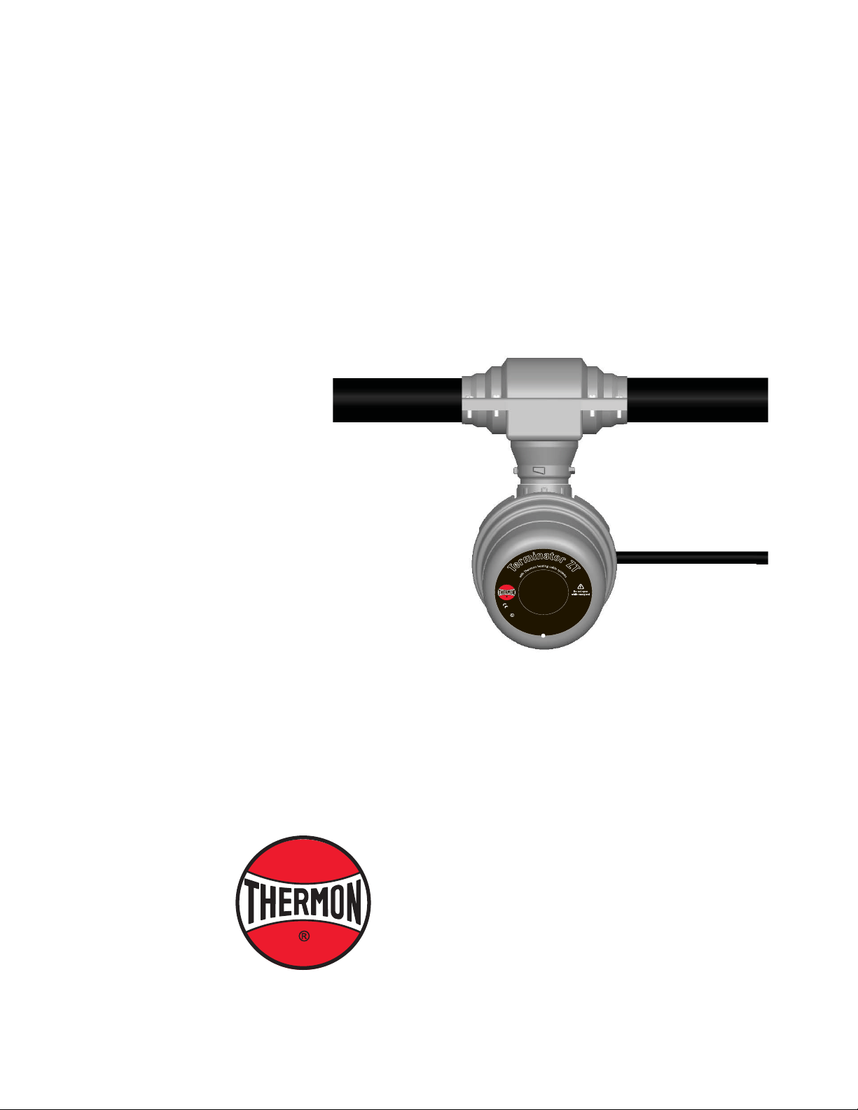
TM
T erminator
ZT / F AK-4L Kit
Thermostat Connection In-Line Power Kit
For Use With TubeTraceTM Bundles
INST ALLA TION PROCEDURES
a
t
n
o
i
r
o
c
m
n
e
l
t
r
b
o
a
l
t
/
s
l
i
u
m
j
Z
d
i
r
t
a
e
r
n
t
a
h
s
e
a
e
s
T
u
r
o
F
PN 27656
I
P
6
6
1
7
-
6
2
0
5
°
C
≤
T
I
a
I
≤
2
+
G
5
D
0
I
E
E
C
x
E
d
x
b
e
F
M
G
1
0
T
e
r
m
o
s
t
a
t
X
C
8
°
5
5
0
8
C
0
T
°
-
X
5
C
E
8
°
T
,
0
A
6
0
0
T
1
1
T
C
°
M
0
C
F
I
4
I
,
+
I
C
°
≤
b
5
t
a
T
8
°
C
b
.
0
x
T
≤
-
E
C
T
°
C
5
,
0
°
,
6
-
1
;
0
0
C
°
0
6
0
T
-
1
T
5
C
I
I
T
I
I
C
I
T
b
5
t
-
C
x
T
E
6
,
I
I
b
e
0
b
2
d
2
x
X
E
The Heat Tracing Specialists
®

TerminatorTM ZT / FAK-4L
1
7
2
5
I
I
2
G
D
E
x
d
b
e
b
I
I
C
T
5
-
T
6
,
E
x
t
b
I
I
I
C
T
1
0
0
°
C
-
T
8
5
°
C
,
F
M
1
0
A
T
E
X
0
0
5
8
X
I
E
C
E
x
F
M
G
1
0
.
0
0
2
2
X
E
x
d
b
e
b
I
I
C
T
5
-
T
6
,
E
x
t
b
I
I
I
C
T
1
0
0
°
C
-
T
8
5
°
C
PN 27656
T
e
r
m
i
n
a
t
o
r
Z
T
F
o
r
u
s
e
a
s
a
n
a
d
j
u
s
t
a
b
l
e
c
o
n
t
r
o
l
/
l
i
m
i
t
e
r
t
h
e
r
m
o
s
t
a
t
I
P
6
6
-
6
0
°
C
≤
T
a
≤
+
5
0
°
C
T
5
,
1
0
0
°
C
;
-
6
0
°
C
≤
T
a
≤
+
4
0
°
C
T
6
,
8
5
°
C
The following installation procedures are suggested
guidelines for the installation of the T erminator ZT / FAK-4L
Thermostat Connection In-Line Power Kit.
Receiving, Storing and Handling . . .
1. Inspect materials for damage incurred during
shipping.
2. Report damages to the carrier for settlement.
3. Identify parts against the packing list to ensure the
proper type and quantity has been received.
4. Store in a dry location.
Terminator ZT / FAK-4L Kit Contents . . .
1
2
4
3
9
6
13
12
7
10
11
15
5
14
Dimensions . . .
Terminator ZT
/FAK-4L
Tools Required . . .
A
B
C
A
inch (mm)
372 mm/14.6 in 308 mm/12.1 in 185 mm/7.3 in
B
inch (mm)
C
inch (mm)
T erminator-LN-Tool
(order separately)
16
17
8
Item Qty Description
11
Expediter Assembly: Support Cap with O-Ring,
Threaded Grommet Compressor, Grommet, Support
Base with O-Ring
2 1 Junction Box Lid
3 1 Junction Box Base with O-Ring and M25 Dust Cap
4 1 Expediter Nut
Thermostat w/ Terminal Blocks
(Refer to terminal specifi cations for maximum allowable wire size)
51
Thermostat Type Control Range
ZT-C-100 0
ZT-C-200 0
ZT-C-300 0
ZT-C-500 20
°C to +100°C
°C to +200°C
°C to +300°C
°C to +500°C
6 1 Junction Box Cord
7 1 Bulkhead Entry Cover (Top)
8 1 Bulkhead Entry Base (Bottom)
9 1 Blind Plug
10 12 Pan Head S.S. Screws, #10-32 x 19mm
11 12 KEPT S.S. Nuts, #10-32
12 3 M5 Screw
13 3 M5 Lock Washer
14 1 Heat Refl ective T ape
15 1 Glass Fiber Tape
16 3 RTV Sealant Tube
17 2 Small Bundle Adapter
Order Separately . . .
PETK Power and End T ermination Kits (per cable)
PETK-1 for RSX, VSX, BSX
PETK-2 for KSX, HTSX
PETK-3-ZT for HPT, FP
1

INST ALLA TION PROCEDURES
The Terminator ZT / FAK-4L Thermostat In-Line Power
Kit is designed to provide accurate control with the ZT
thermostat and make a waterproof seal over the end of
TubeTrace and terminate Thermon electric heat trace in
an approved T erminator junction box. Review Instructions
prior to installation. Kit will make one connection.
Terminator ZT Certifi cations/Approvals . . .
IP66 -60°C Ta +50°C T5, 100°C; -60°C Ta +40°C T6, 85°C
Ordinary & Hazardous Locations
FMG 10.0022X Ex db eb IIC T5-T6, Ex tb IIIC T100°C-T85°C
1725 II 2 GD Ex db eb IIC T5-T6, Ex tb IIIC T100°C-T85°C FM10ATEX0058X
85mm
(3-1/4”)
508mm
(20”)
508mm
(20”)
Tubing Bundle
Tubing
Heat Tracing
Heat Tracing
Self-Regulating Heat Tracing Zone Type Heat Tracing
Installation Precautions . . .
• Keep ends of bundles, heat tracing and kit components
dry before and during installation.
• To minimize the potential for arcing on electrical
heat tracing caused by product damage or improper
installation, use appropriate ground-fault circuit
protection.
• Installation must comply with Thermon requirements
and be installed in accordance with any applicable
national and local codes.
• Component approvals and performance ratings are
based on the use of Thermon specifi ed parts only. User
supplied power connection fi ttings must be listed or
certifi ed for intended use.
• De-energize all power sources before opening
enclosure.
• Individuals installing these products are responsible
for complying with all applicable safety and health
guidelines. Proper personal protective equipment, or
PPE, should be utilized during installation. Contact
Thermon if you have any additional questions.
85mm
(3-1/4”)
Tubing
Tubing
Bus Connection
Indentations
(Zone Heater Only)
Heat Tracing
1.
Remove outer jacket and insulation from tubing
bundle approximately 508mm (20”) from end of
the tubing bundle.
Do not cut or damage the heat
trace or sampling tube.
(Found on TubeTrace SE/ME bundles)
CAUTION
Tube Fitting
(Provided by Others)
Heat Tracing
305mm -381mm
(12” - 15”)
3. Make tube fi tting connections with appropriate
fi tting (provided by others). Test fi tting for leaks
before proceeding. Mount tube fi tting shifted
from each other in case of multiple tubes.
2. Trim tubing to within 85mm (3-1/4”) of the
end of the insulation. If self regulating heat
trace proceed to step 3. For Zone-type heat trace
continue with identifi cation of bus connection on
step 2a.
Heat Tracing
45°
4. Cut the ends of the cable at an angle to aid in
piercing grommet.
2
2a. Strip back bundle insulation 85mm (3 1/4”)
beyond bus connection indentation of each heat
tracing. If bus connection indentation is less than
305mm (12”)-381mm (15”) from end of the heat
tracing, proceed stripping the bundle insulation
to the next indentation. Trim tubes so the bus
connection indentation on each meet.
Cut and Remove
End Pieces to fi t
Splice Cover
To p
Tubing
Bundle
Splice Cover
Heat Tracing
Base
5. Cut splice cover ends to match outside diameter
of tubing bundle. For bundle diameter less than
48mm remove only the closed in part.

TerminatorTM ZT / FAK-4L
Thermostat Sensor
Weep Hole
Expediter Nut
Bulkhead Entry Base
Expediter
Tracing Cable
Junction Box
Base
Heating Cable vs. Sensor Location
Heating Cable
(Typical)
180°
Thermostat
Sensor
Thermostat
6. Route thermostat bulb through expediter nut and expediter opening in
junction box base. If necessary, apply lubricant (user supplied) to the end
of thermostat bulb. Slide through conical grommet hole. Insert the tracing
cables through conical grommet holes and punch out weep hole.
Glass Fiber Tape
Heat Refl ective Tape
Heat Tracing
Capillary
8. Wrap tube and heat trace with 1 pass of refl ective
tape (25% overlap), then wrap with 3 passes of
glass fi ber tape (50% overlap), or until fi ber tape
is equal to original bundle insulation thickness.
M5 Screws
Splice Cover
To p
Glass Fiber Tape
Heat Tracing Capillary
9. Complete with additional passes of heat refl ective
tape.
RTV
Sealant
7. Create a gap between the insulation and the tube with a screw driver for the
sensor and place the sensor inside.
Heat Refl ective Tape
Splice Cover
To p
Splice
Cover
Base
Heat Tracing
RTV Sealant
Capillary
10. Form a gasket by applying RTV sealant to splice
cover base and along radius of splice cover
top as shown.
Small Bundle
Adapters
Splice Cover
Top and Base
Expediter Base
Splice
Cover
Base
Heat Tracing
Expediter Base
Capillary
KEPT
Nuts
11. Assemble splice cover top, tubing bundle, and
splice cover base together as shown, using
10-32 X 19mm pan head screws and KEPT
nuts.
For Bundle Diameters Less Than 64 mm.
11a. Place small bundle adapters as shown. Apply
RTV sealant to spacers liberally.
3
Heat Tracing
180mm
Minimum
Capillary
12. Trim heat tracing to 180mm minimum from
expediter base.

Align Slot
1
7
2
5
I
I
2
G
D
E
x
d
b
e
b
I
I
C
T
5
-
T
6
,
E
x
t
b
I
I
I
C
T
1
0
0
°
C
-
T
8
5
°
C
,
F
M
1
0
A
T
E
X
0
0
5
8
X
I
E
C
E
x
F
M
G
1
0
.
0
0
2
2
X
E
x
d
b
e
b
I
I
C
T
5
-
T
6
,
E
x
t
b
I
I
I
C
T
1
0
0
°
C
-
T
8
5
°
C
PN 27656
T
e
r
m
i
n
a
t
o
r
Z
T
F
o
r
u
s
e
a
s
a
n
a
d
j
u
s
t
a
b
l
e
c
o
n
t
r
o
l
/
l
i
m
i
t
e
r
t
h
e
r
m
o
s
t
a
t
I
P
6
6
-
6
0
°
C
≤
T
a
≤
+
5
0
°
C
T
5
,
1
0
0
°
C
;
-
6
0
°
C
≤
T
a
≤
+
4
0
°
C
T
6
,
8
5
°
C
INST ALLA TION PROCEDURES
Ground Braid
Heat Tracing
Capillary
Power Connection
Boot
13. Terminate heat tracing with appropriate PETK
termination kit. Refer to PETK installation
instructions for details not addressed here.
Tighten cap securely.
16. Install thermostat and complete system
wiring. Terminal set screws shall be tightened
to a torque value of 1.4 Nm (12.4 lb-in). See
step 17 for wiring details. Set thermostat at
desired setpoint.
Grommet
Compressor
14. Mount junction box on expediter making sure to
align slots to properly orient junction box base.
Tighten nut with Terminator-LN-Tool.
Heat Trace #1
N
N
17. Wiring Details:
(1 or 2 Heating Cables)
Heat Trace #2
224
L1
PEPE
Power Supply
L1
N
PE
Thermostat Connection
15. Remove M25 dust cap. Install M25
power gland (order seperately) and
M25 blind plug.
a
t
n
o
i
r
o
c
m
n
e
l
t
r
b
o
a
l
t
/
s
l
i
u
m
j
Z
d
i
r
t
a
e
r
n
t
a
h
s
e
T
o
F
PN 27656
I
P
6
6
1
7
-
6
2
0
5
°
C
≤
I
I
2
G
I
E
C
E
T
e
a
r
m
e
s
o
u
r
T
a
D
x
F
M
s
t
a
t
X
C
8
°
5
5
0
8
C
0
T
°
-
X
5
C
E
8
°
T
,
0
A
6
0
0
T
1
1
T
C
°
M
0
C
F
I
4
I
,
+
≤
+
E
x
d
G
I
C
°
≤
b
5
t
a
5
T
8
0
x
°
T
≤
C
-
E
C
T
°
C
5
,
0
°
,
6
-
1
;
0
0
C
°
0
6
b
0
T
-
1
e
T
b
5
C
I
I
T
I
I
C
I
T
b
5
t
-
C
x
T
E
6
,
I
1
I
0
b
.
0
e
0
b
2
d
2
x
X
E
30º
18. Install junction box lid and twist hand tight.
Insert screwdriver into ratchet slot located
on side of junction box base to tighten. Use
screwdriver ratchet on junction box lid. Lid will
rotate 30°. To remove lid, repeat steps but in
opposite direction.
Junction Box
Tubing Bundle
19. Completed Terminator ZT/FAK-4L power/
thermostat assembly for TubeTrace Type SE/
ME Bundle (Installation shown is to feed power
in the middle of a TubeTrace bundle. Many
installations will be near the end of a TubeTrace
bundle.) Install bundle clamps (order seperately)
300mm before and after In-line power kit.
THERMON . . . The Heat Tracing Specialists
www.thermon.com
European Headquarters
Boezemweg 25
2640 AE Pijnacker
Phone: +31 (0) 15-36 15 370
Specifi cations and information are subject to change without notice. Form PN50090U-1013
PO Box 205
•
The Netherlands
•
®
Corporate Headquarters
100 Thermon Dr.
San Marcos, TX 78667-0609
PO Box 609
•
Phone: +1 512-396-5801
4
USA
•
For the Thermon offi ce nearest you
visit us at . . .
www.thermon.com
 Loading...