

Page 1

Installation Manual
Truck Edition (TSA, EMEIA and AP)
Single Temperature Systems
T-580R, T-80 0M and T-1000M (with TSR Controller)
T-680S, T-88 0S, T-1080S (with SR-3 Controller)
T-600R, T-680R , T-800R, T-880R, T-1000R & T-1080R (with SR-3 Controller)
T-1200R (EMEIA Only with SR-3 Controller)
TK 55212-1-IM (Rev. 4, 01/15)
Page 2

Page 3

Installation Manual
Truck Edition (TSA, EMEIA and AP)
Single Temperature Systems
T-580R, T-800M and T-1000M (with TSR Controller)
T-680S, T-880S, T-1080S (with SR-3 Controller)
T-600R, T-680R, T-800R, T-880R, T-1000R and T-1080R (with SR-3 Controller)
T-1200R (EMEIA Only with SR-3 Controller)
TK 55212-1-IM (Rev. 4, 01/15)
Copyright
©
2011 Thermo King Corp., Minneapolis, MN, U.S.A.
Page 4

2
Installation Manual for T-Series Systems
Release History
Original (09/11) Released
Rev. 1 (02/13) Pages 20, 21, 23, 27 and 29 - Changed art to show revised lifting bar with forged clevis and pins, forged
connecting links and forged locking hooks used for lifting the unit.
Rev. 2 (03/13) Updated manual to include new Tier IV units.
Rev. 3 (10/14) Page 64: Added connection procedures for adding auxiliary power devices.
Rev. 4 (01/15) Page 46: Added important note about fuel tank air vent.
Page 5
3
Installation Manual for T-Series Systems
Page 6

4
Introduction
This manual was written to assist with the installation of Thermo King T-Series Systems onto truck bodies specifically designed and built for these
applications.
Due to its complexity, you should not attempt this installation unless you:
• Are an experienced mechanic.
• Can safely lift 34 kilos (75 lbs.).
• Are certified or trained in the repair and maintenance of dies el powered
refrigeration systems.
• Have a basic understanding of electricity and electrical wiring.
• Have the necessary tools and equipment to complete the installation.
This manual is published for informational purposes only. Thermo King makes no representations warranties express or implied, with respect to
the information recommendations and descriptions contained herein. Information provided should not be regarded as all-inclusive or covering
all contingencies. If further information is req uir ed, Thermo King Corporation Service Department should be consulted.
Thermo King’s warranty shall not apply to any equipment which has been “so installed, maintained, repaired or altered as, in the manufacturer’s
judgment, to affect its integrity.”
Manufacturer shall have no liability to any person or entity for any personal injury, property damage or any other direct, indirect,
special, or consequential damages whatsoever, arising out of the use of this manual or any info rmat i on, recommendations or
descriptions contained herein.
Page 7

5
Table of Contents
Safety Precautions. . . . . . . . . . . . . . . . . . . . . . . . . . . . . . . . . . . . . . . . . . . 6
Unit Dimensions T-580R, T-600R, T-680R, T-680R, T-680S, T-800M,
T-800R, T-880R, T-880S . . . . . . . . . . . . . . . . . . . . . . . . . . . . . . . . . . . . . .8
Unit Dimensions T-1000M, T-1000R, T-1080R, T-1080S and T-1200R 9
Service Area - T-580R, T-600R, T-680R, T-680R, T-680S, T-800M,
T-800R, T-880R, T-880S . . . . . . . . . . . . . . . . . . . . . . . . . . . . . . . . . . . . 10
Service Area - T-1000M, T-1000R, T-1080R, T-1080S and T-1200R . 11
Remote Power Receptacle Dimensions (OPTION) . . . . . . . . . . . . . . . . 12
Battery Box Dimensions (OPTION). . . . . . . . . . . . . . . . . . . . . . . . . . . . 13
Remote Status Light Dimensions (OPTION) . . . . . . . . . . . . . . . . . . . . .14
HMI Controller Dimensions . . . . . . . . . . . . . . . . . . . . . . . . . . . . . . . . . .15
Truck Body Opening Dimensions . . . . . . . . . . . . . . . . . . . . . . . . . . . . . 16
Unit Weights . . . . . . . . . . . . . . . . . . . . . . . . . . . . . . . . . . . . . . . . . . . . . .18
Lifting Bar Details . . . . . . . . . . . . . . . . . . . . . . . . . . . . . . . . . . . . . . . . . 19
Required Tools . . . . . . . . . . . . . . . . . . . . . . . . . . . . . . . . . . . . . . . . . . . . .22
Installation Components. . . . . . . . . . . . . . . . . . . . . . . . . . . . . . . . . . . . . 24
Uncrating the Unit . . . . . . . . . . . . . . . . . . . . . . . . . . . . . . . . . . . . . . . . . .26
Installing the Unit . . . . . . . . . . . . . . . . . . . . . . . . . . . . . . . . . . . . . . . . . .28
Installing the Hose Management Caps. . . . . . . . . . . . . . . . . . . . . . . . . . 30
Installing the Hose Management System (OPTION). . . . . . . . . . . . . . . 32
Securing the Oil Drain Hose . . . . . . . . . . . . . . . . . . . . . . . . . . . . . . . . . . 34
Securing the Evaporator Drain Hoses . . . . . . . . . . . . . . . . . . . . . . . . . . .36
Installing the Fuel Pickup Tube Into a Steel or Aluminum Tank. . . . . . 38
Installing the Fuel Pickup Tube Into a Plastic Tank . . . . . . . . . . . . . . . . 40
Installing the Steel Fuel Tank . . . . . . . . . . . . . . . . . . . . . . . . . . . . . . . . .42
Installing the Aluminum Fuel Tank (OPTION) . . . . . . . . . . . . . . . . . . . 44
Installing the Fuel Pump and Fuel Lines . . . . . . . . . . . . . . . . . . . . . . . . 46
Installing the ServiceWatch™ Remote Download Port (OPTION). . . . 48
Installing the Remote Power Receptacle (OPTION) . . . . . . . . . . . . . . . . 50
Installing the Remote Status Light (OPTION) . . . . . . . . . . . . . . . . . . . .52
Installing the HMI Controller . . . . . . . . . . . . . . . . . . . . . . . . . . . . . . . . .54
Installing the Battery Box (OPTION) . . . . . . . . . . . . . . . . . . . . . . . . . . .56
Battery Connections . . . . . . . . . . . . . . . . . . . . . . . . . . . . . . . . . . . . . . . . .58
Installing the Door Switch (OPTION) . . . . . . . . . . . . . . . . . . . . . . . . . . . 60
Auxiliary Electrical Accessories. . . . . . . . . . . . . . . . . . . . . . . . . . . . . . . 64
UNIT CHECK LIST . . . . . . . . . . . . . . . . . . . . . . . . . . . . . . . . . . . . . . . .65
Page 8
6
Safety Precautions
The symbol appears next to a point that is particularly important:
DANGER: Addresses a circumstance that, if encountered,
will lead to death or serious injury
WARNING: Add resses a c ircumsta nce that, if enco untered ,
might lead to death or serious injury.
CAUTION: Addresses a circumstance that, if enco untered,
may cause damage to eq uipment or minor injury.
DANGER: Never operate the unit with the discharge valve
closed because it could cause the compressor to explode,
causing death or serious in jury.
DANGER: Never apply heat to a sealed refriger ation system o r
container because it could explode, causing death or serious
injury
DANGER: Fluorocarbon refrigerants, in the pres ence of an
open flame or electrical short, produce toxic gases that are
severe respiratory irritants capable of causing death.
DANGER: Be careful when working with a refrigerant or
refrigeration system in any enclosed or confined area with a
limited air supply (i.e., a trailer, container or the hold of a
ship). Refrigerant tends to displace air and can cause oxygen
depletion which may re s ult in death by suffocation.
WARNING: Always wear goggles or safety glasses.
Refrigerant liquid, refrigeration oil, and battery acid can
permanently damage the eyes (see First Aid un der
Refrigeration Oil).
WARNING: Keep your hands away from fans and belts when
the unit is running. This should also be considered when
opening and closing the compressor service valves.
WARNING: Make sure gauge manifold hoses are in good
condition. Never let them come in contact with a belt, fan
motor pulley, or any hot surface.
WARNING: Make sure all mou nti ng bolts are tight and are of
correct length for their particular application
WARNING: Never drill holes in the unit unless absolutely
necessary. Holes dri ll ed into the unit may weaken structural
components. Holes drilled into electric al wiring can cau se fire
or explosion.
WARNING: When using ladders to install or service
refrigeration systems, always observe the ladder
manufacturer’s safety labels and warn ings. A w ork platform is
the recommended method for installations.
WARNING: Exposed coil fins are very sharp and can cause
painful lacerations.Wea r lea ther w ork gloves to prevent i njur y.
Page 9

7
Safety Precautions (continued)
Battery Installation and Cable Routing Refrigerant
First Aid
FROST BITE: In the event of frost bite, the objectives of First Aid are to
protect the frozen area from further injury, to warm the affected area
rapidly and to maintain respiration.
EYES: For contact with liquid, immediately flush eyes with large am ounts
of water and get prompt medical attention.
SKIN: Flush area with large amounts of lukewarm water. Do not apply
heat. Remove contaminated clothing and shoes. Wrap burns with dry,
sterile, bulky dressing to protect from infection/injury. Get medical
attention. Wash contaminated clothing before reuse.
INHALATION: Move victim to fresh air and use CPR or mouth-to-mouth
ventilation, if necessary. Stay with victim until arrival of emergency
medical personnel.
Refrigeration Oil
First Aid
NOTE: In case of eye contact, immediately flush with plen ty of water
for at least 15 minutes. CALL A PHYSICIAN. Wash skin with soap and
water.
WARNING: Im prop erly i ns talled battery cou ld result in a fire or
explosion! A Thermo King approved battery must be instal led
and properly secured to the battery tray.
WARNING: Improperly installed battery cables could result in
fire or explosion! Battery cables must be installed, routed and
secured properly to prevent them from rubbing, chaffing or
making contact with hot, sharp or rotating components.
WARNING: Do not attach fuel lines or any additional wiring
harnesses to the battery cables as this could caus e an
electrical fire!
CAUTION: Set all unit electrical controls to the OFF positio n
before connecting battery cables to the battery to prevent unit
from starting unexpectedly and causing personal injury.
CAUTION: Always wear protective clothing, gloves and eye
wear when handling and installing batteries. Battery acid can
cause serious burns when exposed to eyes or skin. If battery
acid contacts skin or clothing, wash imme diately with soap
and water. If acid enters your eye, immediately flood it with
running cold water for at least twen ty minutes and g et medi cal
attention immediately.
CAUTION: Always cover battery terminals to prevent them
from making contact with metal components during batter y
installation. Battery ter m inals grounding against metal could
cause the battery to explode.
WARNING: Al though fluorocarbon refrigerants are classified
as safe refrigerants, certain precautions must be observed
when handling them or servicing a unit in which they are
used. When released to the atmosphere in the liquid state,
fluorocarbon refrigerants evaporate rapidly , freezing anything
they contact.
WARNING: Av oid refrig eration o il contact with the eyes. Avo id
prolonged or repeated contact of refrigeration oil with skin or
clothing. Wash th oroughly after handling refrigeration oil to
prevent irritation.
Page 10
8
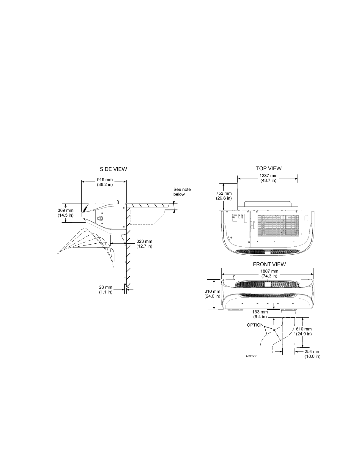
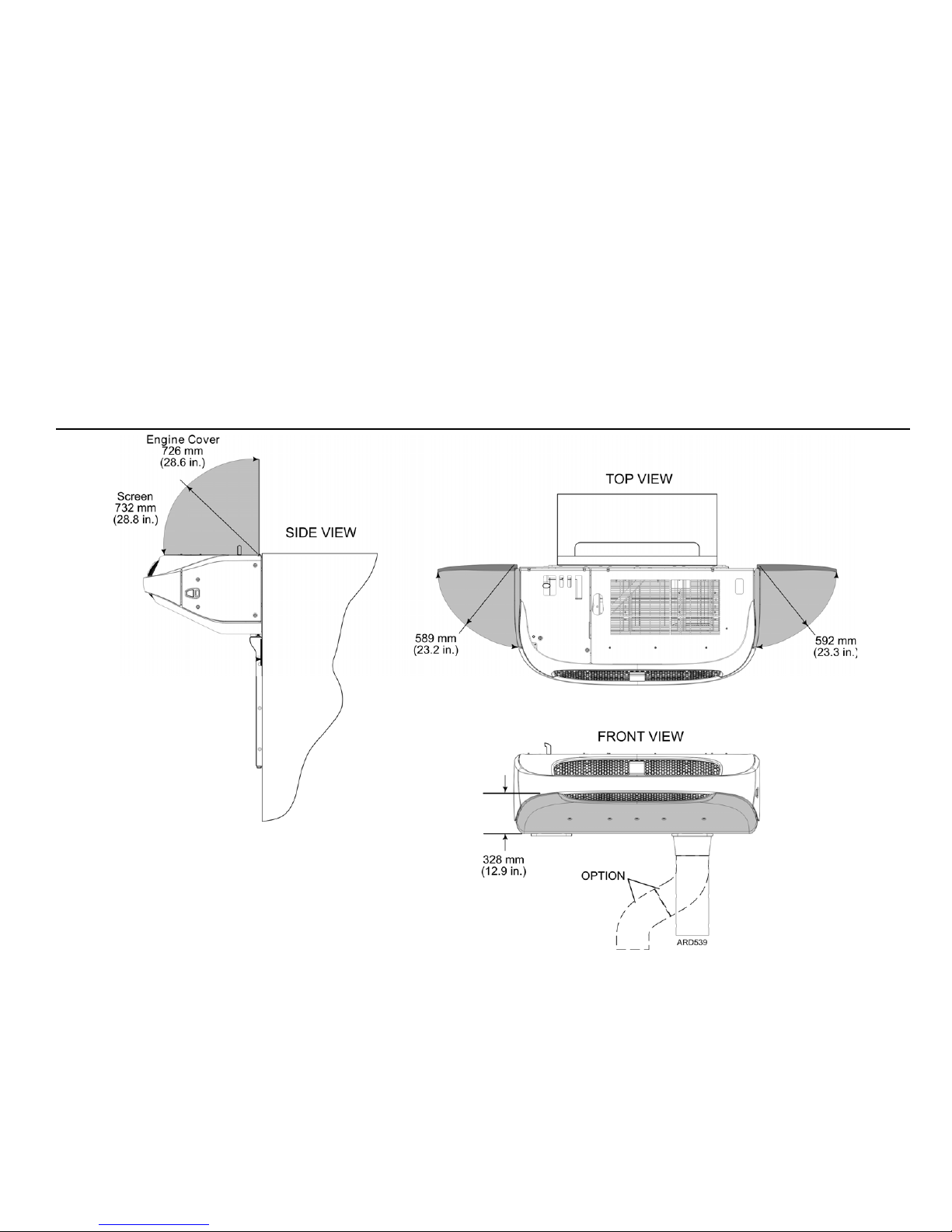
Unit Dimensions - T-580R, T-600R T-680R, T-680R, T-680S, T-800M, T-800R, T-880R, T-880S
NOTE: The top of the unit to be mounted flush with the top of the cargo box when
possible. The top of the evaporator to be positioned 25.4 mm (1.00 in.) below ceiling.
The dimension from the top of the cargo box to the evaporator cutout will vary
depending on the type of box, truck cab tilt clearance. etc.
T-580 th rough T-880 series units minimum dimension = 107 mm (4.2 5 in.)
Page 11
9
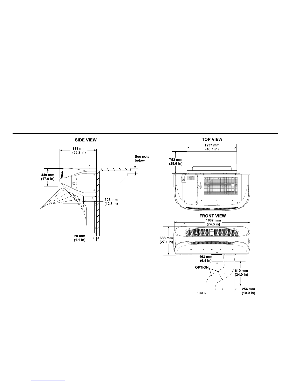
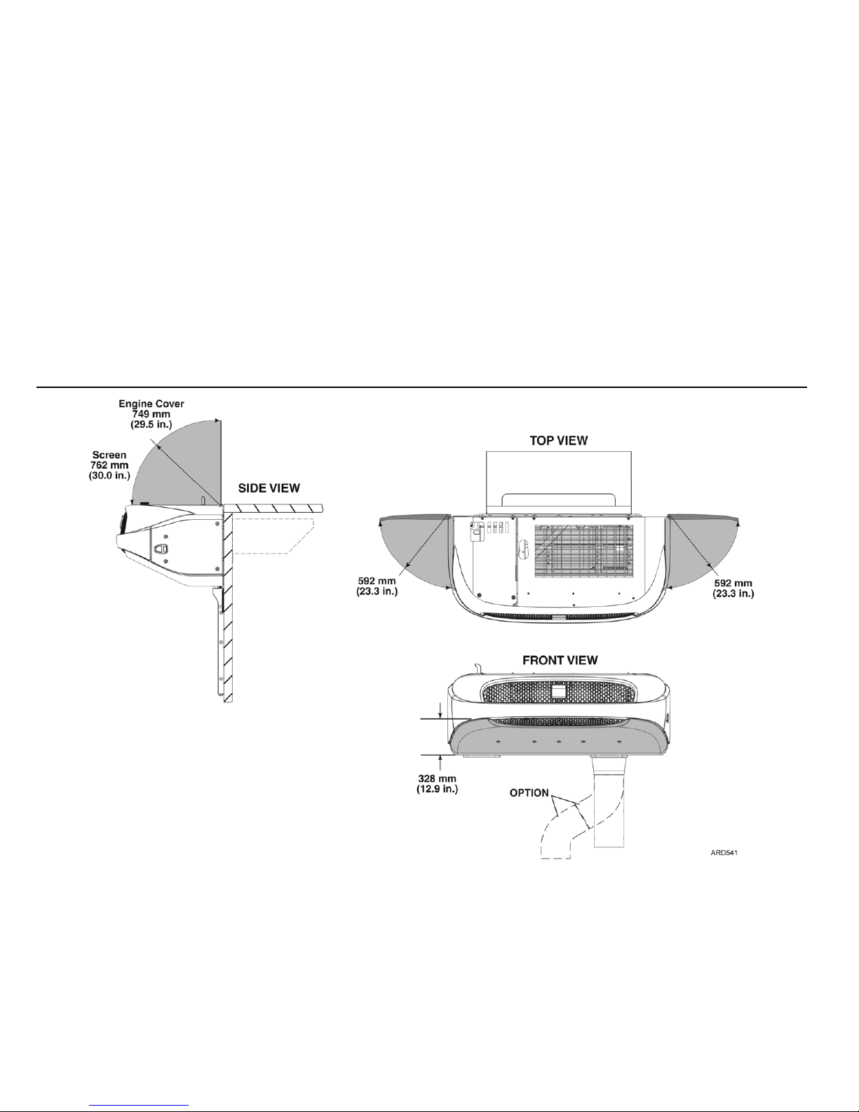
Unit Dimensions T-1000M, T-1000R, T-1080R, T-1080S and T-1200R
NOTE: The top of the unit to be mounted flush with the top of the cargo box when
possible. The top of the evaporator to be positioned 25.4 mm (1.00 in.) below ceiling.
The dimension from the top of the cargo box to the evaporator cutout will vary
depending on the type of box, truck cab tilt clearance. etc.
T-1000 through T-1200 series minimum dimension = 147 mm (5.75 in.)
Page 12
10
Service Area - T-580R, T-600R T-680R, T-680R, T-680S, T-800M, T-800R, T-880R, T-880S
Page 13
11
Service Area - T-1000M, T-1000R, T-1080R, T-1080S and T-1200R
Page 14
12
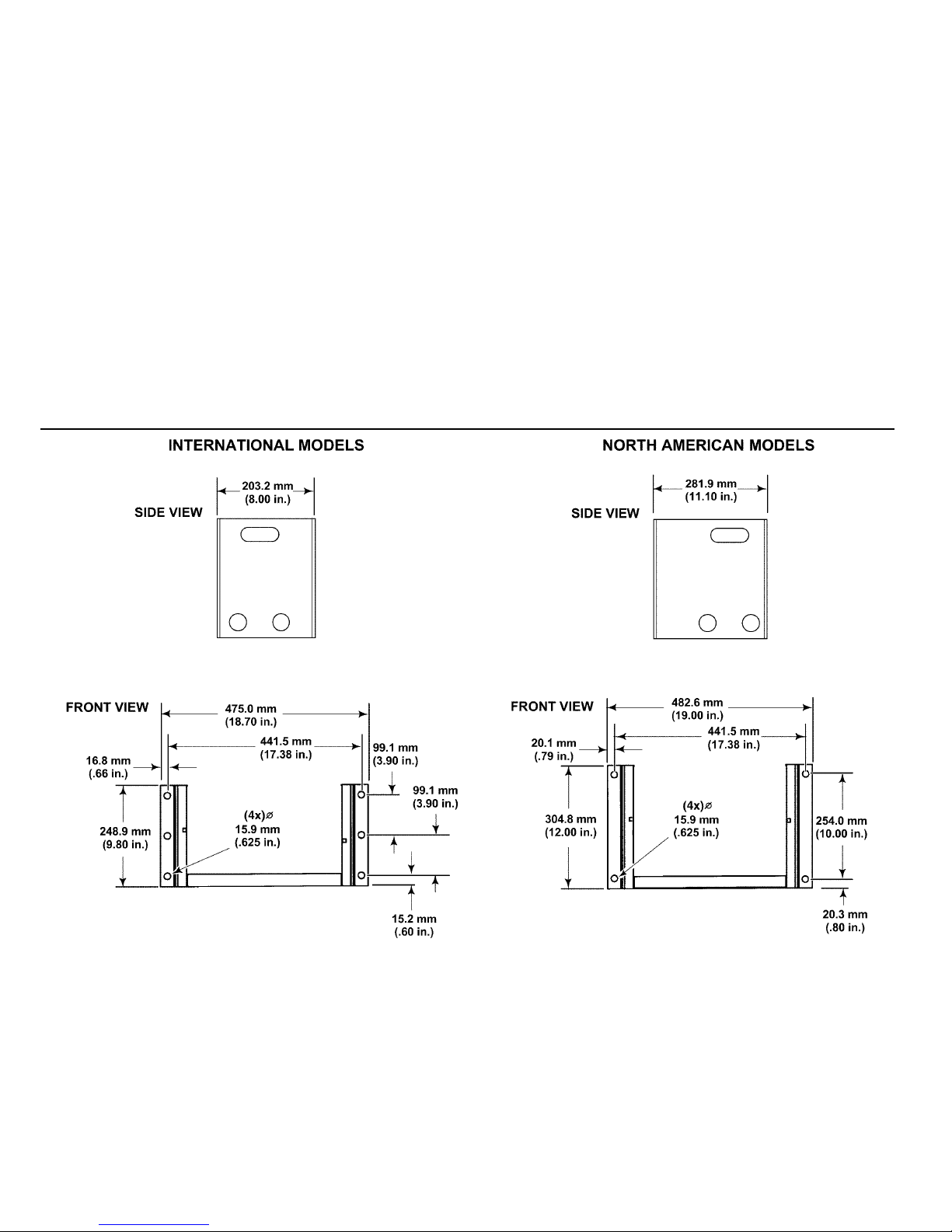
Remote Power Receptacle Dimensions (OPTION)
NORTH AMERICAN MODELS
INTERNATIONAL MODELS
Page 15
13
Battery Box Dimensions (OPTION)
Page 16
14
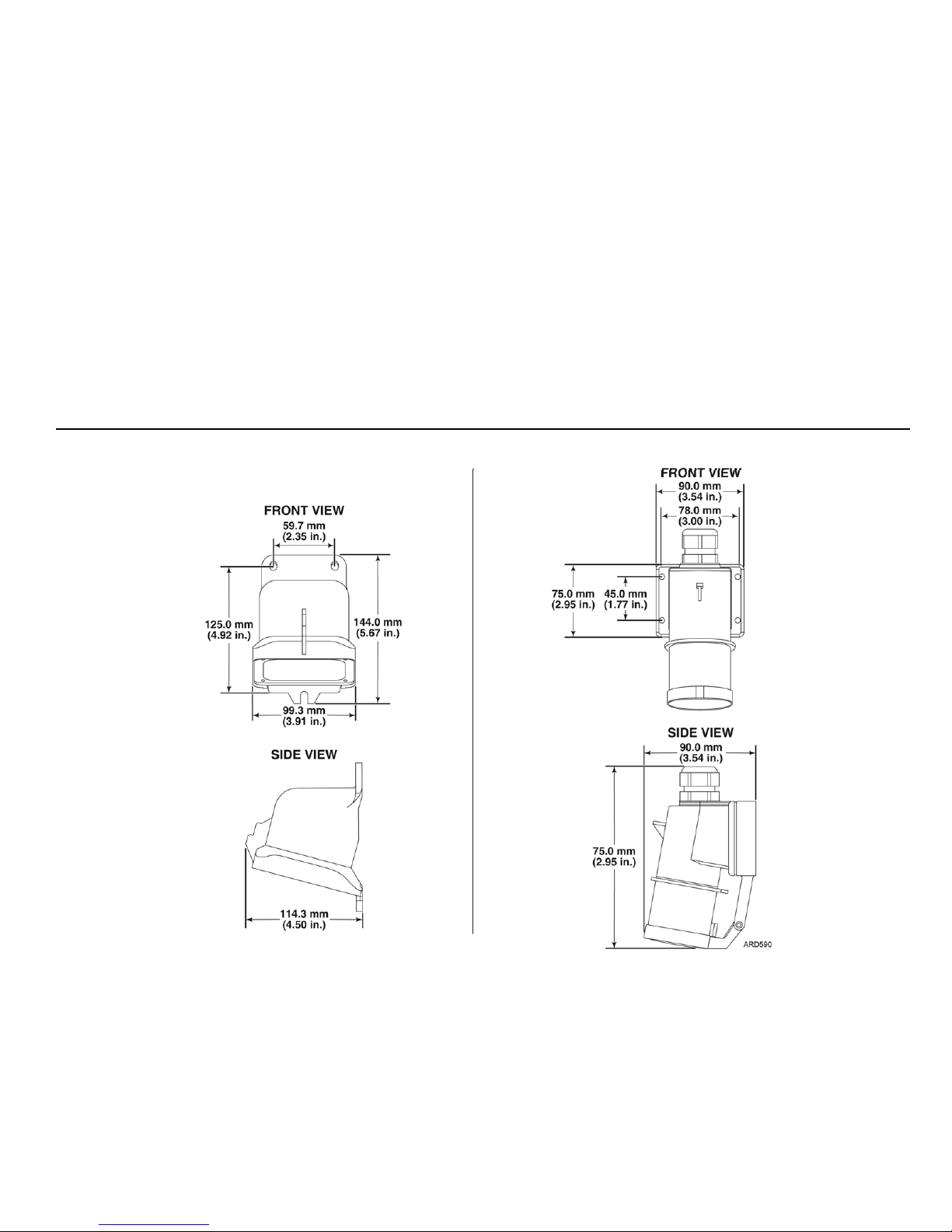
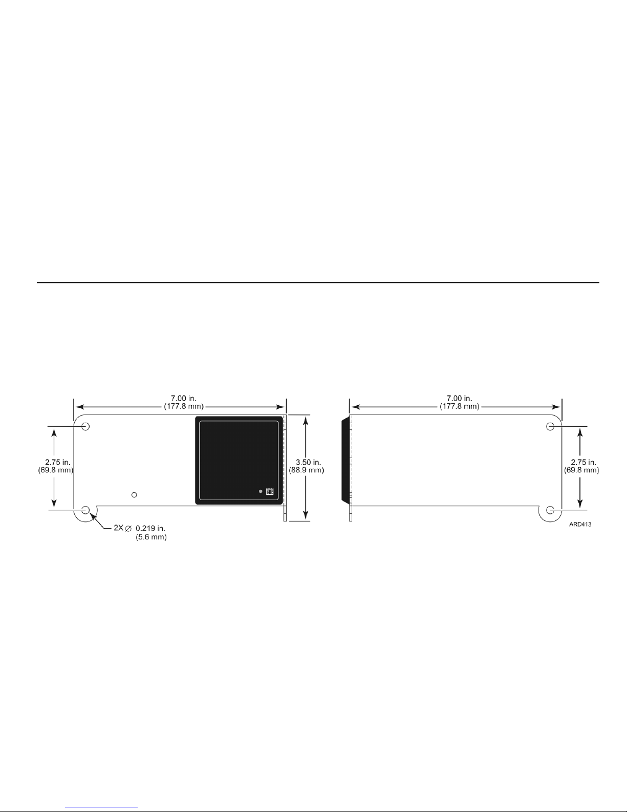
Remote Status Light Dimensions (OPTION)
Page 17
15
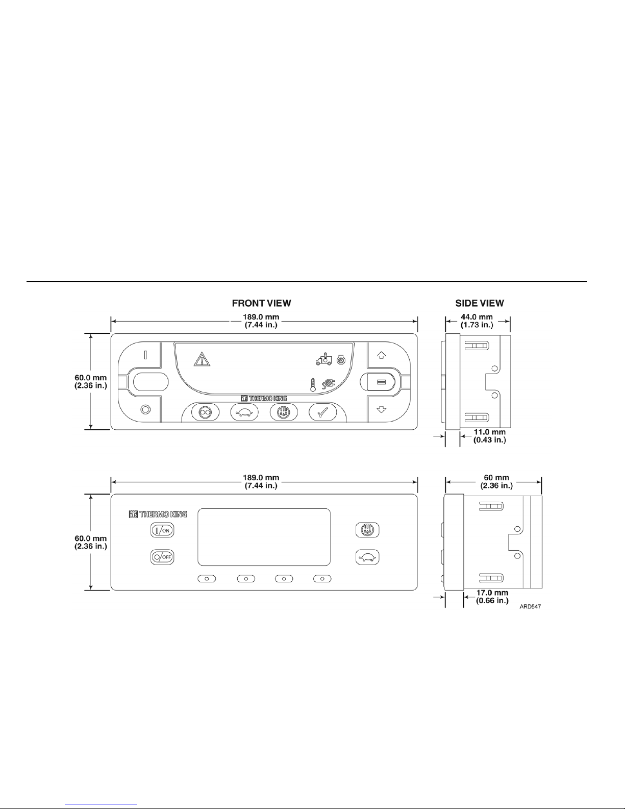
HMI Controller Dimensions
HMI Controller (LED Display)
HMI Controller (Graphics Display)
Page 18
16
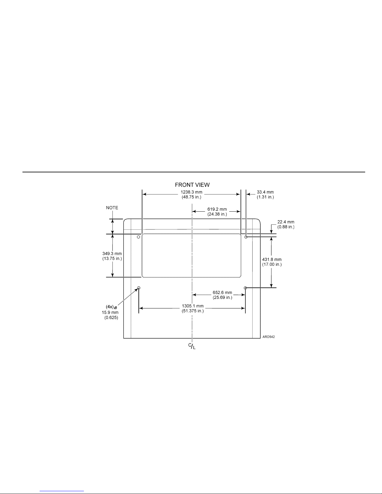
Truck Body Opening Dimensions
Installing a New Unit onto a New Truck Box
Important Installation Requirements:
• Gasket sealing surface of 50.8 mm (2.00 in.) wide is required around the unit opening. This surface must be flat within 6.4 mm (0.25 in.) and free of all rivets or head b o
proper gasket sealing.
• The top of the evaporator to be positioned 25.4 mm (1.00 in.) below ceiling.
• Unit mounting location must allow for adequate tilt clearance (see Unit Dimensions ).
NOTE: The top of the unit to be
mounted flush with the top of t he
cargo box when possible. The
top of the evaporator to be
positioned 25.4 mm (1.00 in.)
below ceiling.
The dimension from the top of
the cargo box to the evaporator
cutout will vary dependin g on the
type of box, truck cab tilt
clearance. etc.
T-580 through T-880 series
minimum dimension = 107 mm
(4.25 in.)
Page 19
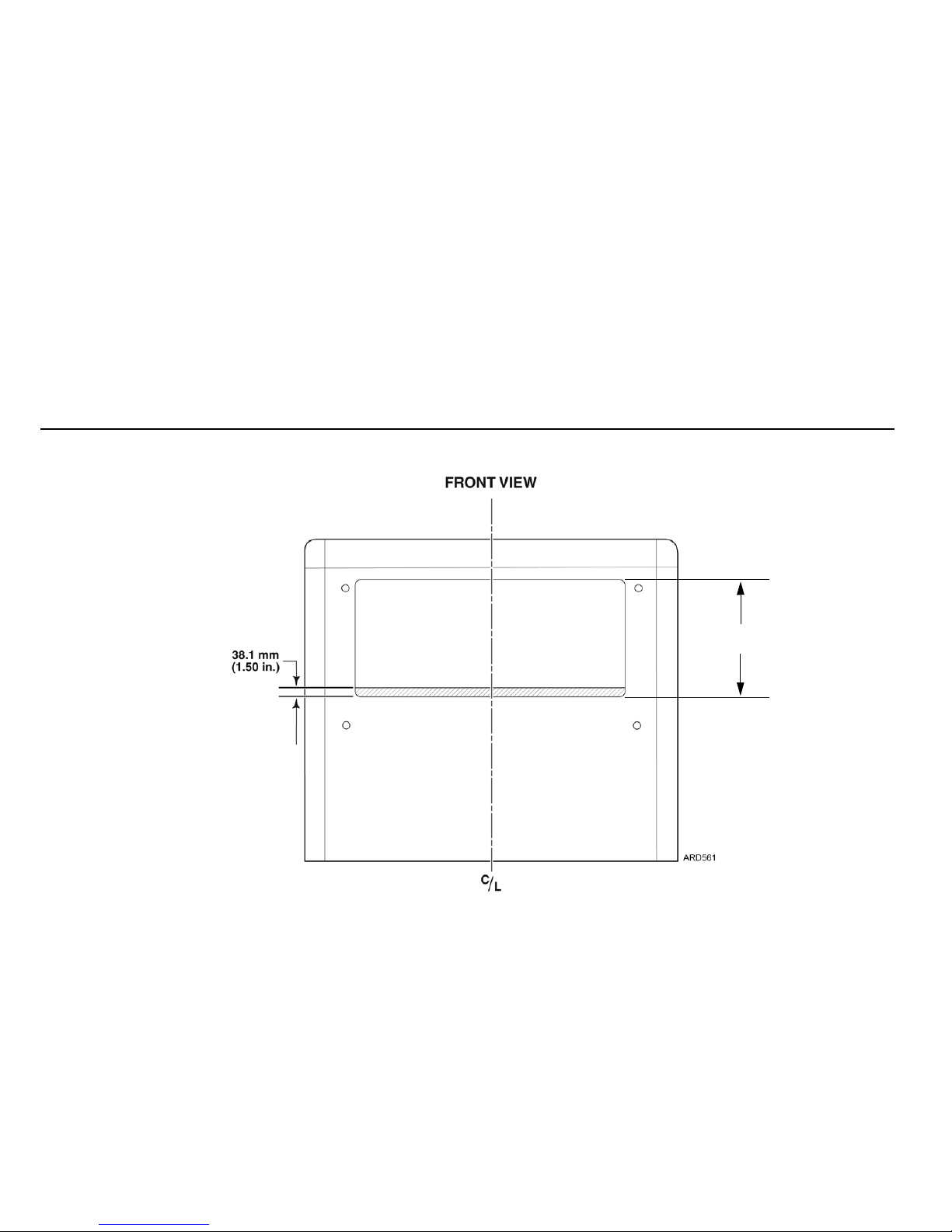
17
Truck Body Opening Dimensions
Retrofitting a New Unit onto a Older Truck Box
Important Installation Requirements:
• Gasket sealing surface of 50.8 mm (2.00 in.) wide is required around the unit
opening. This surface must be flat within 6.4 mm (0.25 in.) and free of all rivets or head bolts for proper gasket se aling.
• Evaporator to be positioned 25.4 mm (1.00 in.) below ceiling.
• Unit mounting location must allow for adequate tilt clearance (see Unit Dimensions ).
NOTE:
Existing opening same as
RD-II, TS-500 and TS-600 units
and does not require
modifications.
Opening must only be enlarged
when changing from a TS-200,
TS-300, MD-100, MD-200,
MD-300, MD-II or KD-II
349.3 mm
(13.75 in.)
Enlarge Opening as shown (See
Page 20

18
Unit Weights
Model 30 Units (approximate weight) Model 50 Units (approximate weight)
CAUTION: The truck wall must be structurally strong enough to support the weight of the refrigeration unit.
T-580R 434 kg (957 lbs.)
T-600R 443 kg (977 lbs.)
T-680R 437 kg (963 lbs.)
T-680S 447 kg (985 lbs.)
T-800R 443 kg (977 lbs.)
T-880R 437 kg (963 lbs.)
T-880S 447 kg (985 lbs.)
T-800M 443 kg (977 lbs.)
T-1000M 476 kg (1029 lbs.)
T-1000R 461 kg (1016 lbs.)
T-1080R 453 kg (999 lbs.)
T-1080S 459 kg (1012 lbs.)
T-1200R 475 kg (1046 lbs.)
T-580R 459 kg (1012 lbs.)
T-600R 468 kg (1032 lbs.)
T-680R 462 kg (1018 lbs.)
T-680S 472 kg (1040 lbs.)
T-800R 468 kg (1032 lbs.)
T-880R 462 kg (1018 lbs.)
T-880S 472 kg (1040 lbs.)
T-800M 468 kg (1032 lbs.)
T-1000M 516 kg (1138 lbs.)
T-1000R 510 kg (1125 lbs.)
T-1080R 502 kg (1108 lbs.)
T-1080S 508 kg (1121 lbs.)
T-1200R 524 kg (1155 lbs.)
Page 21

19
Lifting Bar Details
IMPORTANT: All T-580 through T-1200 series truck units require a new
lifting bar. This new bar must be used to safely lift and install these series
units. This new lifting bar can also be used to install earlier series truck
units.
WARNING: Thermo King requires a 3 point lifting bar to safely
lift and install units. A lifting bar can be made from the drawings
provided.
WA R NING : All h ard ware us ed to asse mble the li f t ing bar m ust be
DIN 931 class 10.9 (SAE Grade 8). The use of hardware other
than specified may cause personal injury, severe damage to the
equipment and void the warranty.
WARNING: Use forged clevis and pins, forged chain links and
forged locking hooks with strength equal to total lift capacity of
hoist mechanism and that meet all safety standards.
Page 22

20
Lifting Bar Details
A
B
C
D
A
B
C
D
87654321
87654321
SIZE DWG NO REV
TITLE
DRAWN DATE
THIRD ANGLE PROJECTION
D
REVISIONS
CHANGE ORDER
REV DESCRIPTION DATE APPROVED
CODE IDENT NO
CHECKED
APPROVED
ENG APPVLFINISH
CAD GENERATED DRAWING,
DO NOT MANUALLY UPDATE
UNLESS OTHERWISE SPECIFIED TOLERANCES
ON DIMENSIONS PER TKS09109
DIAGRAM-LIFTING BAR ASS'Y
FOR SELF-POWERED
LARGE TRUCK
-
--
6/15/90RL
6/15/90TB
1/20/88JO
NOTES:
2. USE TWO CHAIN LINKS WITH A CHAIN LINK MASTER AS SHOWN.
3. USE THREE FORGED CLEVIS AND PINS TO ATTACH LIFTING CHAINS.
4. EACH ASSEMBLY MUST HAVE STRENGTH EQUAL TO MINIMUM OF 1.5 TIMES
THE WEIGHT OF THE HOIST AND MEET ALL SAFETY STANDARDS.
2
1
4
3
5
ENTIRE UNIT
CLEVIS LIFTING
HOLES (1-5)
SCALE 0.250 SHEET 1 OF 2
J
9127C30
INGERSOLL-RAND IS THE SOLE OWNER OF THIS
DRAWING AND ALL INFORMATION IN IT, WHICH ARE
PROTECTED BY COPYRIGHT AND OTHER LAWS AND MAY
BE SUBJECT TO LAWS REGARDING EXPORTING
INFORMATION OUTSIDE OF THE U.S. THIS DRAWING
MAY BE USED ONLY BY ITS RECIPIENTS FOR THE
PURPOSE FOR WHICH IT IS PROVIDED AND ONLY BY
THE RECIPIENT, WHO AGREES THAT IT WILL NOT,
WITHOUT INGERSOLL-RAND'S PRIOR WRITTEN
PERMISSION: 1) DISCLOSE NOR USE THIS DRAWING
OR THE INFORMATION IN IT EXCEPT AS SPECIFIED
ABOVE; OR 2) MAKE ANY COPIES OF OR EXTRACTS,
REVISIONS, OR UPDATES FROM THE DRAWING. ALL
COPIES MUST BE RETURNED TO INGERSOLL-RAND
UPON COMPLETION OF THE WORK FOR WHICH THEY
HAVE BEEN PROVIDED OR UPON ANY EARLIER
REQUEST.
UNLESS OTHERWISE SPECIFIED
DIMENSIONS ARE IN INCHES.
INTERPRET DIM AND TOL PER
ASME Y14.5M - 1994
M GILMAN
18-Jun-08
MOVED LIFTING HOLES ALONG REAR BAR,
ADDED BRIDGING BAR FOR SPECTRUM TS
LIFTING POINT. ADDED WELD SYMBOLS,
RE-LABLED ALL LIFTING POINTS
F529536
M GILMAN
25-Mar-09
ADDED LIFTING HOLES FOR NEW UNITS,
ADDED BRIDGING BAR FOR MULTI-TEMPS.
G532334
E KIRBY
20-Jan-10
DIM 17.22 WAS 16.42. DIM 11.12 WAS
10.42. ADDED TSERIES SPECTRUM VIEW
H539147
M GILMAN
14-Jun-10
CHG DRAWING AND VIEWS, MOVED HOLES 1-6,
ADDED TABLE FOR ALL TRUCK UNITS.
I543699
J.DAVIES27-NOV-12
REMOVED CHAINS, BOLTS FROM VIEW SHT 1,
DEL NOTE 2.
J665985
Thermo King
UNIT
TYPE
FRONT
CHAIN LIFT
HOLE LOCATION
ENTIRE UNIT
CLEVIS LIFTING
HOLE LOCATION
TS 200/300/500/600 - 30 LEFT HOLE 1
TS 200/300/500/600 - 50 LEFT HOLE 2
SPECTRUM TS LEFT HOLE 4
MD II, MD 200, MD 300 - 30 RIGHT HOLE 1
MD II, MD 200, MD 300 - 50 RIGHT HOLE 2
KD II - 30 RIGHT HOLE 1
KD II - 50 RIGHT HOLE 2
RD II - 30 RIGHT HOLE 1
RD II - 50 RIGHT HOLE 2
T SERIES - 30/50 LEFT HOLE 3
T SERIES SPECTRUM LEFT HOLE 5
RELEASED 14/Jan/2013
Page 23

21
Lifting Bar Details
A
B
C
D
A
B
C
D
87654321
87654321
SIZE DWG NO REV
D
CODE IDENT NO
7.9
54.2
3.5
3.5
27.1
.50 THICK
3.5
1.75
2X .75
25.1
50.20
26.60
3X .875
1.75
23.50
28.70
.534
4.0
1.75
.534
4.0
2.4
1.75
2X .75
7.5
1.75
1.0
8.85
11.45
5.0
4X .534
1.75
1.0
8.85
11.45
5.0
4X .534
4.0
R1.25
(30.3)
.50 THICK
3.5
2X .75
1.75
4X .534
2X .8
2X 3.4
21.1
21.1
2X 58°
(2X )122°
2X 58°
23.6
11.2
17.2
2X 58°
31.7
2.1
2.1
9127C30
J
SHEET 2 OF 2SCALE 0.250
SCALE 0.250
REAR MEMBER
SCALE 0.250
FRONT MEMBER
SCALE 0.150
WELDING DETAIL
FRONT MEMBER
CENTER MEMBER
REAR MEMBER
SCALE 0.250
CENTER MEMBER
I
2X
2X
I
I
I
I
I
(1.6)
(1.4)
Page 24

22
Required Tools
1. Safety Glasses
2. Drill
3. Drill Bits
4. Tape Measure
5. Mechanics Tools
6. Lifting Bar (New Style Design Required) with forged clevis and pins,
forged connecting links and forged locking hooks.
7. Work Platform (Recommended)
Page 25

23
Required Tools
Page 26

24
Installation Components
1. Unit Mounting Washers 1.250 x 0.188 THK
2. Locking Nuts 1/2-13
3. Torx Head Screws
4. Hose Management Cap s
5. Hold Down Clamps
6. #14 Sheet Metal Screws
7. Drain Hose Check Valves
8. Fuel Pump
9. Fuel Pump Bracket
10. Screws HH 1/4-20 SS
11. Locking Nuts 1/4-20 SS
12. Fuel Pickup Tube
13. Fuel Line Fittings
14. Clamps
15. Self Tapping Screws #10 HWHSM
16. In-Line Fuse Holder
17. Fuse 60 amp
18. Terminal Connector Splice
19. Heat Shrink Sleeving 3.00''
20. Terminal Red 3/8''
21. Terminal Lug 3/8''
22. Cable Ties
23. Muffler Gasket
24. Exhaust Tube Extension
25. Nut-Blind
26. HMI Controller
27. HMI DIN Mount
28. Oil Drain Hose Retainer
Page 27

25
Installation Components
Page 28

26
Uncrating the Unit
Important Unit Lifting Information
NOTE: All T-580 through T-1200 series truck units require a new lifting
bar. This new bar mus t be used t o saf ely lift and install these series unit s.
See “Lifting Bar Details” on page 19.
Uncrating the Unit
Carefully remove the top and side crate member and remove the bottom
panel and installation kit components shipped with the unit.
1. Remove the top covers, top screen (if equipped) and the muffler from
the unit.
2. Install two M12 eyebolts and washers into the lifting holes in the rear
frame rails, and tighten securely. NOTE: M12 eyebolts must be used as
M12 nuts are factory installed inside the rear frame channel.
3. Install a third M12 eyebolt, washer and locking nut into the provided
hole in the support channel as shown and tighten hardware securely.
4. Attach the new three point lifting bar secu rely to t he t hree eyebolts a nd
slightly raise the unit.
5. Remove the eight skid bracket screws securing the unit to the of the
crate (Detail C).
6. Remove the two rear members of the crate and raise the unit from base
approximately 304.8 mm (12.0 in.) (Detail C).
7. Remove the four mounting bolts securing the two upright members to
the unit (Detail C).
The unit is now ready to install.
WARNING: Thermo King requires a 3 point lifting bar to safely
lift and install units. A lifting bar can be made from the drawings
provided. See “Lifting Bar Details” on page19 .
WARNING: Use forged clevis and pins, forged chain links and
forged locking hooks with strength equal to total lift capacity of
hoist mechanism and that meet all safety standards.
WARNING: Inst aller su pplied lifting eyebolts must be forged steel,
12 mm, 1.75 pitch, minimum 20.5 mm long. Substitutions are not
acceptable!
WARNING: Use only locking lifting hooks to attach to the lifting
eyebolts (Detail A).
WARNING: The point shown in Detail B below is not a major
lifting point. It is used only
to level and balance the unit during
installation (Detail B).
Page 29

27
Uncrating the Unit
Page 30

28
Installing the Unit
Important Unit Lifting Information
NOTE: All T-580 through T-1200 series truck units require a new lifting
bar. This new bar mus t be used t o saf ely lift and install these series unit s.
See “Lifting Bar Details” on page 19.
NOTE: The T-570R, T-600, T-600R, T-800, T-800R and T-1000 series
truck units have dual mounting hole patterns in the frame.
• T-570R, T-600, T-600R, T-600M, T-800 and T-800R use the lower
dual mounting hole patterns.
• T-1000, T-1000R and T-1000M use the upper mounting hole
patterns.
Installing the unit
NOTE: The muffler must not be installed before mounting the unit.
1. Use the new 3 point lifting bar to carefully lift the unit up to the truck
opening.
2. Install four M12 (1/2-13 in. Grade 5) mounting bolts through the wall
of the truck box.
NOTE: The mounting bolts should protrude 73.3 mm (2.90 in.) full
thread from the front wall of the cargo box (Detail B). Carefully sli de the
unit into the opening and over mounting bolts.
IMPORTANT: DO NOT INSTALL ANY COMPRESSIBLE WASHERS
OR OTHER MATERIALS BETWEEN THE UNIT AND THE TRUCK!
3. On the inside of the unit frame, install the four 4.8 mm (0.188 in.)
mounting washers and the locking nuts provided in the installation kit.
• Torque the mounting hardware to 81.4 N•m (60 ft. lbs.).
• Disconnect and remove the lifting bar.
NOTE: Depending on your particular installation, excess threads of the
upper roadside unit mounting bolt may need to be cut off to prevent
interference with the muffler.
4. Reinstall the muffler and the new gasket supplied in kit onto the engi ne.
• Torque the muffler mounting bolts to 18.4 N•m (13.6 ft. lbs).
• Install the exhaust pipe onto the muffler and tighten securely.
5. Remove and save the three M12 eyebolts installed earlier.
6. Reinstall the top cover or screen (if applicable) securely.
7. Install the bottom pan securely using the supplied M6 Torx head
mounting hardware.
WARNING: Thermo King requires a 3 point lifting bar to safely
lift and install units. A lifting bar can be made from the drawings
provided. See “Lifting Bar Details” on page19.
WARNING: Use forged clevis and pins, forged chain links and
forged locking hooks with strength equal to total lift capacity of
hoist mechanism and that meet all safety standards.
WARNING: Inst aller su pplied lifting eyebolts must be forged steel,
12 mm, 1.75 pitch, minimum 20.5 mm long. Substitutions are not
acceptable!
WARNING: Use only locking lifting hooks to attach to the lifting
eyebolts (Detail A).
WARNING: The point shown in Detail B below is not a major
lifting point. It is used only
to level and balance the unit during
installation (Detail B).
Page 31

29
Installing the Unit
Page 32

30
Installing the Hose Management Caps
Hose Management Caps (STANDARD)
Hose management caps provide a exit point under each side of the unit for
routing the individual drain hoses, fuel lines, electrical cables. The caps are
provided with cutout guide marks. Always remove any sharp edges after
cutting the caps.
Roadside Cap
1. Route the following items out of the roadside cutout of the bottom pan
and down the front exterior wall of the cargo box:
• Roadside Evaporator Drain Hose
• In-Cab Controller Harness
• Remote Receptacle Power Cable (Model 50 Units Only)
Curbside Cap
2. Route the following items out of the curbside cutout of the bottom pan
and down the front exterior wall of the cargo box:
• Curbside Evaporator Drain Hose
• Coolant Overflow Hoses (2)
• Fuel Supply and Return Lines (2)
• Positive and Negative Battery Cables (2)
• Unit Control Power Wire
• Fuel Pump Harness
• Oil Drain Hose (See “Securing the Oil Drain Hose” on page 34).
3. Trim the cutout areas on the caps as required.
4. Install each cap securely into the bottom pan.
Page 33

31
Installing the Hose Management Caps
Cutout Guide Marks
Front
of
Unit
Page 34

32
Installing the Hose Management System (OPTION)
Hose Management System (OPTION)
The hose management system organizes the routing of the drain hoses,
electrical cables and fuel lines down the truck wall. White plastic covers
protect these components from damage while providing a cleaner, finished
installation.
The kit consists of a funnel cap, clip assemblies, straight covers and
mounting hardware. Additional kits with offset covers are also available.
IMPORTANT: See “Securing the Oil Drain Hose” on page 34.
1. Route the following items out of the curbside cutout of the bottom pan
and down the front exterior wall of the cargo box:
• Curbside Evaporator Drain Hose
• Engine Overflow Hose
• Fuel Supply and Return Lines
• Positive Battery Cable
• Unit Control #2 Power Wire
• Fuel Pump Harness
• Negative Battery Cable
2. Install the funnel cap into the bottom pan securely.
3. Mark a line from the center of the funnel cap down the truck box wall.
4. Install two clip assemblies onto each cover with supplied hardware.
• Insure the surface area of the truck box is clean, flat and uniform.
• Clean the surface area thoroughly with 50:50 mixture of isopropyl
and water.
• Peel the backing off the adhesive strips. Using the center line,
position the covers and press firmly into position.
• Remove the covers from the clips.
NOTE: If adequate bond was not possible, attach the clips securely with
self-drilling screws.
5. Route and install the hoses and cables in the clips as shown.
6. Reinstall the covers securely.
7. Installation on the roadside is similar.
NOTE: For 50 Models ONLY. Route the standby power cable down the
center of the clip assemblies.
Page 35

33
Installing the Hose Management System (OPTION)
Front
of
Unit
Page 36

34
Securing the Oil Drain Hose
Oil Drain Hose
1. Secure the oil drain hose directly under the unit to the cargo box with
the two supplied retaining clips and self tapping screws as shown.
2. Ensure there is no contact and adequate clearance be tween the oil drain
hose and the hose management caps. The cutout in the hose
management cap should be as large as possible with no sharp edges.
3. Lower retaining clip should be positioned in an location easily
accessible for servicing the unit. Your actual location will depend on
the distance between the bottom of unit to top of cab, etc.
Page 37

35
Securing the Oil Drain Hose
The cutouts in the hose mana gemen t cap
should be as large as possible with no
sharp edges.
Page 38

36
Securing the Evaporator Drain Hoses
IMPORTANT: Evaporator drain hoses must be installed without any
sharp bends or kinks to allow for proper water drainage.
1. Route drain hoses from under the unit, through the Hose Management
Caps and down the front wall of the truck box.
2. Secure drain hoses with supplied self tapping screws and clamps.
3. Cut off excess drain hose and install a check valve onto each drain hose
securely with tie bands.
Page 39

37
Securing the Evaporator Drain Hoses
Page 40

38
Installing the Fuel Pickup Tube Into a Steel or Aluminum Tank
NOTE: The fuel pickup tube supplied in the installation kit will not be
needed when installing an optional Thermo King aluminum fuel tank.
The aluminum tank is already equipped with fuel inlet, fuel outlet and
vent fittings.
1. Tape the paper template (supplied with pickup tube) to the desired
location on the diesel fuel tank and center punch the three holes.
NOTE: Use a magnet, grease or special hole saws/drills that will
minimize metal or aluminum chips from entering the fuel tank.
Thoroughly clean and flush the tank to remove any chips.
2. Drill:
• 9.5 mm (0.375 in.) diameter holes first.
• 31.8 mm (1.250 in.) diameter hole next.
• Remove the template from the tank and remove any burrs from the
hole.
3. Cut the end of the pickup tube so approximately 25 mm (1.00 in.) is
above the bottom of the fuel tank.
4. Loosen the nut and slide all the parts to the top of the pickup tube
assembly.
5. Hold the parts in position and slide the assembly into the hole at a slight
angle until the bushing is inside the hole.
6. Tip the backup washer and sl ide it through t he hole and pos it ion it onto
the bushing. Thread the nut onto the bushing, position as needed to
facilitate fuel line connections and tighten to 54 Nm. (40 ft-lb.).
DANGER: Diesel fuel vapors are potentially explosive. Use
extreme caution when drilling in or around the diesel fuel tank.
Sparks from an electric drill or drill bit could cause an explosion.
Do not smoke while working near the diesel fuel tank. Drain all
diesel fuel from the tank and use nitrogen or an inert gas to purge
the diesel fuel vapors from the tank prior to drilling. Keep the
diesel tank filled with inert gas while drilling.
Page 41

39
Installing the Fuel Pickup Tube Into a Steel or Aluminum Tank
Page 42

40
Installing the Fuel Pickup Tube Into a Plastic Tank
1. Tape the paper template (supplied with pickup tube) to the desired
location on the diesel fuel tank and center punch the three holes.
NOTE: Use grease or special hole saws/drills that will minimize
plastic chips from entering the fuel tank Thoroughly clean and flush
the tank to remove any chips.
2. Drill:
• 9.5 mm (0.375 in.) diameter holes first.
• 31.8 mm (1.250 in.) diameter hole next.
• Remove the template from the tank and remove any burrs from the
hole.
3. Cut the end of the pickup tube so approximately 25 mm (1.00 in.) is
above the bottom of the fuel tank.
4. Loosen the nut and slide all the parts to the top of the pickup tube
assembly.
5. Hold the parts in position and slide the assembly into the hole at a slight
angle until the bushing is inside the hole.
6. Tip the backup washer and sl ide it through t he hole and pos it ion it onto
the bushing. Thread the nut onto the bushing, position as needed to
facilitate fuel line connections and tighten to 54 Nm. (40 ft-lb.).
DANGER: Diesel fuel vapors are potentially explosive. Use
extreme caution when drilling in or around the diesel fuel tank.
Sparks from an electric drill or drill bit could cause an explosion.
Do not smoke while working near the diesel fuel tank. Drain all
diesel fuel from the tank and use nitrogen or an inert gas to purge
the diesel fuel vapors from the tank prior to drilling. Keep the
diesel tank filled with inert gas while drilling.
Page 43

41
Installing the Fuel Pickup Tube Into a Plastic Tank
Page 44

42
Installing the Steel Fuel Tank
IMPORTAN T: Observe the positioning of existing OEM fasteners on the
vehicle frame. The four fasteners used to install the fuel tank brackets
must be located on the frame no
higher and no lower than any existing
OEM fasteners.
1. The fuel tank mounting brackets should be positioned 610 mm (24.00
in.) apart to properly support the combined weight of 118 kg (260 lbs.)
which includes the fuel tank, mounting brackets and 30 gallons of
diesel fuel.
• Measure and mark the location of the four mounting holes on the
frame.
• Use a 17 mm (11/16 in.) drill bit and drill four holes in the frame.
2. Install each fuel tank mounting bracket securely onto the truck’s frame
with two, 1/2 -13, Grade 5 bolts, flat washers and locking nuts.
Substitutions are not acceptable!
• Torque the bolts to 81-88 N•m (60-65 ft-lb.).
3. Install the mounting bands T-bolts onto the mounting brackets with flat
washers and locking nuts.
4. Install the fuel tank into the mounting bands.
• Torque the upper mounting band T-bolts to 47 N•m (35 ft-lb.).
IMPORTANT: Do not over tighten the mounting band bolts or damage to
the bands will result!
DANGER: An improperly installed fuel tank could l ead to seri ous
injury or death! Consult your truck’s chassis manufacturer for
specific details on proper fuel tank installation and
recommendations.
Page 45

43
Installing the Steel Fuel Tank
1
2
3
4
Page 46

44
Installing the Aluminum Fuel Tank (OPTION)
IMPORTANT: Observe the positioning of existing OEM fasteners on the
vehicle frame. The four fasteners used to install the fuel tank brackets
must be located on the frame no
higher and no lower than any existing
OEM fasteners.
1. The fuel tank mounting brackets should be positioned 610 mm (24.00
in.) apart to properly support the combined weight of 118 kg (260 lbs.)
which includes the fuel tank, mounting brackets and 30 gallons of
diesel fuel.
• Measure and mark the location of the four mounting holes on the
frame.
• Use a 17 mm (11/16 in.) drill bit and drill four holes in the frame.
2. Install each fuel tank mounting bracket securely onto the truck’s frame
with two, 1/2 -13, Grade 5 bolts, flat washers and locking nuts.
Substitutions are not acceptable!
• Torque the bolts to 81-88 N•m (60-65 ft-lb.).
3. Install the mounting bands onto the mounting brackets with flat
washers and locking nuts.
• Tighten only the lower T-bolt to 47 N•m (35 ft-lb.).
• Install the self-adhesive rubber strips onto each mounting bracket
as shown.
4. Install the fuel tank into the mounting bands.
• Confirm the rubber strips on both the mounting bands and the
mounting brackets are positioned correctly to prevent metal to
aluminum contact.
• Torque the upper mounting band T-bolts to 47 N•m (35 ft-lb.).
IMPORTANT: Do not over tighten the mounting band bolts or damage to
the bands will result!
DANGER: An improperly installed fuel tank could lead to ser ious
injury or death! Consult your truck’s chassis manufacturer for
specific details on proper fuel tank installation and
recommendations.
Page 47

45
Installing the Aluminum Fuel Tank (OPTION)
1
2
3
4
Page 48

46
Installing the Fuel Pump and Fuel Lines
NOTE: Do not connect unit fuel lines into any truck/trailer fuel lines.
1. The fuel pump must be installed as close to the fuel tank as possible
and not more than 762 mm (30.00 in.) above the fuel in the fuel tank.
2. Fuel lines should be routed in a protective housing with no kinks or
sharp bends.
3. Rubber grommets must be used when routing fuel lines through sheet
metal.
4. Secure all fuel lines with provided clamps.
5. Remove the protective plugs from each of the fuel pick up tubes on t he
fuel tank and install fuel line fittings.
6. From the unit, route and install the fuel supply line to the upper fuel
line fitting on the fuel pump. Tighten the fuel line fittings securely.
7. From the fuel pump, route the lower fuel supply line to the fuel tank.
• Cut the end of the nylon fuel supply line at a 45 degree angle and
insert into one of the fuel line fittings.
• Feed the fuel line down into the tank until it hits bottom, then pull it
back up 25 mm (1.00 in.) and tighten the fuel line fitting securely.
8. From the unit, route the fuel return line to the fuel tank.
• Insert the fuel return line into the other fuel line fitting and tighten
the fuel line fitting securely.
9. Remove the plastic cap from the fuel vent and point the outlet towards
the rear of the truck.
IMPORTANT: The factory installed fuel tank air vent must be in place
and functional for the Thermo King unit’s fuel system to operate
correctly and for the fuel tank to remain in compliance with Federal
Motor Carrier Safety Administration specifications (title 49, paragraph
393.67). A plugged or restricted fuel t ank air vent can result in premature
damage to the fuel pump and could also cause severe damage to the fuel
tank. NEVER
remove or install any other component in place of the fuel
tank air vent.
10. Operate the unit and check all fuel line fittings for fuel leaks.
DANGER: The Thermo King fuel pump should be installed onto
the supplied mounting bracket. The fuel pump and fuel lines
should be installed a safe distance away from the extreme heat
generated by the Diesel Particulate Filter (DPF) or exhaust system
components on the truck. Failure to do so could result in damage
to equipment or fire!
DANGER: Leaking fuel lines could cause a fire resulting in death
or serious injury All fuel lines must be tight and leak free!
DANGER: Do not route fuel lines with battery cables or electrical
wires, as this could cause a fire!
S=Supply R=Return
Page 49

47
Installing the Fuel Pump and Fuel Lines
Page 50

48
Installing the ServiceWatch™ Remote Download Port (OPTION)
Choose an appropriate location to mount the ServiceWatch port that
provides for safe and easy access for connecting the download cable. The
download port can be rotated to fit your particular installation.
1. Attach the download port securely to the truck box with four TEK
screws.
2. Provide a drip loop and secure the harness with supplied clamps and
screws.
Page 51

49
Installing the ServiceWatch™ Remote Download Port
Page 52

50
Installing the Remote Power Receptacle (OPTION)
Choose an appropriate location to mount the power receptacle that
provides for safe and easy access for connecting the power cord.
North American Units (Detail A)
1. Measure and drill three 13 mm (.500 in.) holes into truck body.
2. Insert the supplied rubber blind nuts into each hole in truck body.
3. Install the receptacle to the truck box with the supplied 1/4 x 20
mounting hardware and tighten securely.
4. Route and secure the harness with supplied clamps and screws.
International Units (Detail B)
1. Measure and drill four 9.5 mm (.375 in.) holes into truck body
2. Insert the supplied rubber blind nuts into each hole in truck body.
3. Install the receptacle to the truck box with the suppli ed 10-32 mounting
hardware and tighten securely.
4. Route and secure the harness with supplied clamps and screws.
DANGER: To prevent serious injury or death, the electric standby
power cord must not be connected to the unit during installation!
Page 53

51
Installing the Remote Power Receptacle (OPTION)
Page 54

52
Installing the Remote Status Light (OPTION)
Installation
1. Mount the Status Light in a location so that i s visible to the dri ver in the
truck’s mirror.
• Mark and drill the four mounting holes using a 3/16'' drill.
• Mount the status light securely with the supplied rivets.
2. Provide a “drip-loop” to prevent water from migrating into the Status
Light and route the harness towards the bottom of the unit.
3. Secure harness to the truck box using the supplied clamps and rivets.
4. Remove the bottom pan from the unit and locate the 6-pin connector
under the unit near the control box.
5. Remove the blank plug and attach the Status Light connector securely.
6. Secure excess harness up under the control box with band wraps.
7. Reinstall bottom pan.
Page 55

53
Installing the Remote Status Light (OPTION)
Page 56

54
Installing the HMI Controller
NOTE: Route and secure the controller harness to prevent rubbing,
chafing or making contact with sharp, moving or hot components. Allow
excess harness for tilt cab applications. The supplied rubber grommets
must be used when routing harness through sheet metal holes.
Inside Cab DIN Mounting
1. Install DIN (ISO 7736) mounting sleeve into driver panel DIN opening.
Bend the mounting sleeve tabs to secure.
2. Route the controller harness from the unit to insi de the cab and t hrough
the mounting sleeve.
HMI Controller (LED Display) - Insert the controller harness to the
mating connector at the rear of the HMI controller until it locks firmly in
position.
• Lightly pull on the harness to confirm the harness is locked
securely.
• Install the plug cover onto the rear of the controller with the two
supplied screws.
HMI Controller (Graphics Display) - Install the harness plug cover onto
the rear of the controller with the four supplied screws.
3. Install the HMI controller into mounting sleeve until it locks in
position.
Page 57

55
Installing the HMI Controller
NOTE: HMI with LED Display shown, HMI with Graphics Display installs the same.
Page 58

56
Installing the Battery Box (OPTION)
1. Secure battery in place with hold down bracket and rod.
2. Rubber grommets must be used where cables a nd fuse holder ent er box.
3. DO NOT install protective battery cover. This will be installed later.
CAUTION: Battery boxes and covers must be installed securely
with proper hardware to prevent them from falling off.
CAUTION: Battery cables must be properly routed and secure to
prevent rubbing, chafing or making contact with sharp, moving or
hot components.
Page 59

57
Installing the Battery Box (OPTION)
Page 60

58
Battery Connections
Important Battery Information
IMPORT ANT: See Safety Precautions - “Battery Installation and Cable
Routing” on page 7 for additional information.
NOTE: Thermo King units are designed for one 12 vol t , group 31
battery. The battery must be suitable for deep cycling, heavy duty
and rated with a minimum of 95 amp/hr.
Positive Cable
1. At the unit, locate the lar ge black cable ma rked POS+. Route this cable
to the battery, cut to the proper length and add battery cable lug from
installation kit (Detail A). This cable will be attached to the battery in
Step 2.
Unit Control Power Wire
2. At the unit, locate the large 8 AWG (#2) wire. Route this wire to the
battery, cut to the proper length and add fuse holder assembly.
• Use battery cable crimper to securely crimp 8 AWG (#2) wire and
fuse holder together and heat shrink the connection.
• Apply a liberal amount of Superlube to the 60 amp fuse and fuse
holder and then install fuse.
• Route the fuse holder terminal along with the positive cable
(POS+) into the battery box through the rubber grommet and
connect to the POSITIVE terminal of the battery (Detail A).
Fuel Pump Harness
3. Route and connect the fuel pump harness to the fuel pump.
Negative Cable
4. At the unit, locate the large black cable mar ked NEG -. Route this cable
to the battery, cut to the proper length and add the battery lug from
installation kit.
• Route the negative cable (NEG -) into the battery box through the
rubber grommet and connect to the NEGATIVE terminal of battery
(Detail B).
5. Install the battery box cover securely.
6. All harnesses and battery cables should be neatly routed and secured
with provided clamps.
Page 61

59
Battery Connections
Page 62

60
Installing the Door Switch (OPTION)
When installing CargoLink wireless door switches, see TK 55151 CargoLink Installation Manual.
NOTE: These instructions are intended as reference guide only to
assist with a typical door switch install ation. Y our ins tallation may be
different depending o n the cargo b ox, the amou nt and types o f doors
and the customers particular requirements.
Door Switch Components
The door switch consists of a magnet, a switch, non-magnetic mounting
hardware and a interface harness to connect to the host unit.
• The magnet is always mounted on the door.
• The switch (with harness) is always mounted to a stationary location.
Non-magnetic mounting hardware is included to install the switches. If
alternate hardware is used it must also be non-magnetic or the door switch
will not operate properly.
Installer is to supply and fabricate the harness connecting the interface
harness to the door switch per the table below. The harness should be 18
AWG or better, 3 wires, color coded RED, BLACK and WHITE
Mounting Locat ions
The door switch can be mounted on the inside or outside of either swing
out or roll-up doors and can be mounted in various positions to
accommodate particular applications.
IMPORTANT INSTALLATION NOTES:
• The door switch must be installed away from traffic (i.e. forklifts) or
protected from it.
• The door switch and magnet must be installed parallel to each other,
not perpendicular. Long cross hair aligns to long cross hair.
• It is important that a maximum gap of 19 mm (0.75 in.) is maintained
between the door switch and the magnet. Shims may be required and
must be a non-magnetic material (alumi num, wood, plas tic , etc.) or th e
door switch will not operate properly.
(Detail A) Ceiling Mounted
1. Mount the magnet flush with the top edge of the door and secure with
supplied hardware.
2. Close the door and mount the switch to the door sill parallel with the
magnet, being sure the “cross hairs” are aligned and that the maximum
gap of 19 mm (0.75 in.) is maintained.
(Detail B) Floor Mounted
1. Mount the magnet flush with the bottom edge of the door and secure
with supplied hardware.
2. Close the door and mount the switch to the floor parallel with the
magnet, being sure the “cross hairs” are aligned and that the maximum
gap of 19 mm (0.75 in.) is maintained.
(Detail C) Outside Door Installation
1. Mount the magnet flush with the top edge of the door and secure with
supplied hardware.
2. Close the door and mount the switch to the door sill parallel with the
magnet, being sure the “cross hairs” are aligned and that the maximum
gap of 19 mm (0.75 in.) is maintained.
Interface Harness Wiring Door Switch Wiring
RED = (DSP) POWER RED = (DSP) POWER
BLACK = (CH) GROUND BLACK = (CH) GROUND
WHITE = (DS) OUTPUT WHITE = (DS) OUTPUT
Page 63

61
Installing the Door Switch (OPTION)
Right Angle Mounting
Top x Top Mounting
Side x Side Mounting
Page 64

62
Installing the Door Switch (OPTION)
NOTE: The Door Switch Harness Connectors are located at the rear of the host unit.
1. Attach the interface harness to matching door switch connector located
at the rear of the host unit.
2. Route a 3 wire harness (INSTALLER SUPPLIED) from the interface
harness to a door switch. Connect matching wires per the table below
(RED/RED, WHITE/WHITE, BLACK/BLACK) to each door
switch using splice connectors. Crimp splice connectors securely and
apply heat with a heat gun.
3. All harnesses should be installed, routed and properly secured to
protect from damage.
4. Operate unit and verify door switch operation.
Interface Harness Wiring Door Switch Wiring
RED = (DSP) POWER RED = (DSP) POWER
BLACK = (CH) GROUND BLACK = (CH) GROUND
WHITE = (DS) OUTPUT WHITE = (DS) OUTPUT
Page 65

63
Installing the Door Switch (OPTION)
Interface Harness Wiri ng Door Switch Wiring
RED = (DSP) POWER RED = (DSP) POWER
BLACK = (CH) GROUND BLACK = (CH) GROUND
WHITE = (DS) OUTPUT WHITE = (DS) OUTPUT
Page 66

64
Auxiliary Electrical Accessories
NOTE: Thermo King does not recommend adding auxiliary electrical accessories to the electrical system of T-80 Series Self Powered Truck Units
equipped with SR-3 Controllers and Tier 4 Engines. However, if auxiliary accessories are connected to the electrical system, see the following guidelines
to ensure emission compliance for the Ti er 4 engines. The function and safety of the auxiliary access ory connected to t he Thermo K ing electrical syste m is
the customer’s responsibility.
Electrical Connection Guidelines
• Connect the 12 volt load to the 2 terminal (J24) on the Base
Controller.
•Use (J8) Pin 4 to control a 12 volt relay. The relay will be energized
when the unit is on.
• DO NOT connect ground wires for el ectrical acce ssories t o the CH
terminal (J23) on the Base Controller. Use independent ground
wires connected to the chassis ground or the negative battery
terminal.
Use (J8) Pin 4 to 12 Volt Relay Connection
DO NOT Connect Ground
Wires to CH Terminal (J23)
SR-3 Base Controller
J8 Pin 4
Location
4
2 T erminal (J24)
12 Volt Load
Connection
Page 67

65
UNIT CHECK LIST
UNIT CHECK LIST
Visually inspect the unit for transit and handling damage. File claim
with delivery carrier.
Install the unit as outlined in the Thermo King Installation Manual.
If the unit has a separate fuel tank add 10 gallons of fuel to the tank.
BEFORE STARTING THE UNIT
Check battery and battery cable installation.
Inspect fuel line routing checking for rubbing, chaffing or laying on
hot surfaces.
Visually inspect the unit for the following: Loose or improperly
fitting bolts, brackets, hardware, hose connections and hose routing.
Inspect all wiring connections and routing.
Check defrost drain hoses and kazoos.
Check unit mounting hardware for tightness.
Check compressor and engine mounts.
Check compressor clutch if equipped.
Install refrigeration gauge manifold. (Multi-Temp units only)
Check engine oil level.
Check condenser and evaporator section for cleanliness and signs of
refrigerant leaks.
Check front bulkhead and air chute if equipped.
Check damper door, bushings and springs.
MULTI-TEMP UNITS (REMOTE EVAPORATORS)
Check evaporator(s) sections for cleanliness.
Leak test interconnecting tubing.
Check for damage, loose or missing bolts and hardware on remote
evaporator(s).
Check for proper installation of drain tubes, drain kazoos and drain
tube heater wires.
Check for properly routed refrigerant lines wiring harnesses for
remote evaporator(s). Check for proper ly routed harnesses for remote
controller.
Check for proper installation of remote evaporator guards if
equipped.
Check remote harness wiring plugs in the host evaporator.
Check wiring, connections, and terminals in the remote
evaporator(s).
Check compartment bulk head(s) for proper fit if equipped.
START AND RUN UNIT
(ON MULTI-TEMP UNITS START ONLY THE HOST UNIT)
Check for proper oil pressure, coolant temperature, oil, fuel, or
coolant leaks.
Check alternator charge.
Cycle the unit and ensure the unit functions in the corr ect modes and
the mode indicators are working.
Set for continuous run with thermosta t set point a t 32 F (0 C) a nd run
the unit to 32 F (0 C).
Page 68

66
UNIT CHECK LIST (continued)
Observe and record refrigerant operating pressures in relation to
ambient and box temperatures.
Verify the readings above are correct for the conditions.
When box reaches 32 F (0 C) check calibration of thermostat,
thermometer and data logger.
Run unit for 30 minutes at 32 F (0 C). During this period check for
correct cycling.
Reset thermostat to 50 F (10 C).
Check throttling valve while in the heat cycle.
Check operation of Modulation system if equipped.
For Single Temp units perform a controlled check of the refrigerant
level. For Multi-temps check the charge per multi-temp unit
procedures.
MULTI-TEMP UNITS
Install the compartment bulk head(s) if equipped.
Check for correct rotation of remote evaporator fans.
Check for correct cycling and operation of remote evaporator fans.
ALL UNITS
Initiate and check defrost operation and terminat ion.Check operat ion
and adjustment of damper door and remote fans. Each zone on
multi-temps must be checked for proper operation.
Set the unit for Cycle Sentry Operation.
Check for proper operation of all door switches.
Remove the compartment bulk head(s) if equipped.
Set the unit for continuous run. Continue to run the unit with the back
doors open, alternating between high speed cool and heat until at
least 6 hours (10 hours preferred) are shown on the engine run time
hour meter to ensure complete break in of the engine, time for the
belts and other moving parts to take out the initial tension and
adjustment.
ELECTRIC STANDBY OPERATIONAL CHECKS
Test AC electrical contacts and connections by connecting to AC
power and running.
Check for correct electric motor rotation.
Cycle thermostat and check for correct modes of operation.
Power source not available to test AC.
STOP UNIT
On Multi-temp units leak test interconnecting tubing.
Check and readjust all belt tensions using TK belt gauge 204-427.
Check for oil, fuel, coolant, refrigerant and exhaust leaks.
Check engine oil and coolant level.
Check entire unit for loosened hardware and fittings.
Check and adjust all skin, door and panels for correct alignment and
operation.
Complete the commissioning registration process.
Release unit.
Page 69

67
Page 70

 Loading...