


Operator’s Manual
Precedent
TM
C-600, S-600 and S-700
Single Temperature Units
TK 56218-2-OP (Rev. 1, 12/15)


Precedent
TM
C-600, S-600 and S-700
Single Temperature Units
TK 56218-2-OP (Rev. 1, 12/15)
Copyright© 2015 Thermo King Corp., Minneapolis, MN, USA
Printed in USA

Disclaimer
This manual is published for informational purposes only. Thermo King Corporation makes no
representations or warranties, express or implied, with respect to t he information, recommendations
and descriptions contained in this manual and such information, recommendations and description s
should not be regarded as all-inclusive or covering all contingencies. In the event you have any
questions or require further information, please contact your local Thermo King dealer.
The procedures described herein should only be undertaken by suitably qualified personnel. Failure to
implement these procedures correctly may cause dam age to the Th ermo King unit or o ther property or
personal injury.
Thermo King Corporation and its affiliates shall have no liability in contract or tort (including negligence
and/or strict liability) or otherwise, to any person or entity fo r any personal injury, property damage or
any other direct, indirect, special or consequential damage or liability whatsoever, arising out of or
resulting from any actions by any person that are contrary to this manual or any of the information ,
recommendations or descriptions contained herein or the failure of any person to implement the
procedures described herein correctly or to follow caution and safety decals located on the Thermo
King unit.
2

Table of Contents
Introduction . . . . . . . . . . . . . . . . . . . . . . . . . . . . . . . . . 6
EPA Emission Control System Warranty Statement 7
Responsibilities . . . . . . . . . . . . . . . . . . . . . . . . . . . . . . . 8
Thermo King Corporation Responsibilities . . . . . . . 8
Owner Responsibilities . . . . . . . . . . . . . . . . . . . . . . 8
Limitations . . . . . . . . . . . . . . . . . . . . . . . . . . . . . . . . . . . 9
Safety Precautions . . . . . . . . . . . . . . . . . . . . . . . . . . 10
General Safety Practices . . . . . . . . . . . . . . . . . . . . . . 10
Automatic Start/Stop Operation . . . . . . . . . . . . . . . . . 10
Electrical Hazard . . . . . . . . . . . . . . . . . . . . . . . . . . . . . 10
Battery Installation and Cable Routing . . . . . . . . . . . . 11
Refrigerant . . . . . . . . . . . . . . . . . . . . . . . . . . . . . . . . . 12
Refrigerant Oil . . . . . . . . . . . . . . . . . . . . . . . . . . . . . . . 12
First Aid . . . . . . . . . . . . . . . . . . . . . . . . . . . . . . . . . . . . 13
First Aid–Refrigerant . . . . . . . . . . . . . . . . . . . . . . . 13
First Aid–Refrigerant Oil . . . . . . . . . . . . . . . . . . . . 13
Safety Decals and Locations . . . . . . . . . . . . . . . . . . . 13
Condenser and Evaporator Fans . . . . . . . . . . . . . 13
High Voltage Components . . . . . . . . . . . . . . . . . . 14
Do Not Use Ether Starting Aids . . . . . . . . . . . . . . 15
Unit Description . . . . . . . . . . . . . . . . . . . . . . . . . . . . .16
Unit Overview . . . . . . . . . . . . . . . . . . . . . . . . . . . . . . . .16
Diesel Engine . . . . . . . . . . . . . . . . . . . . . . . . . . . . . . . .17
ELC (Extended Life Coolant) . . . . . . . . . . . . . . . . . . . .17
EMI 3000 . . . . . . . . . . . . . . . . . . . . . . . . . . . . . . . . . . .17
Thermo King Reciprocating Compressor . . . . . . . . . . .18
Electronic Throttling Valve . . . . . . . . . . . . . . . . . . . . . .18
SMART REEFER 4 (SR-4) Control System . . . . . . . . .18
Diesel Operation . . . . . . . . . . . . . . . . . . . . . . . . . .19
Electric Operation . . . . . . . . . . . . . . . . . . . . . . . . .19
CYCLE-SENTRYTM Start-Stop Controls . . . . . . . . . .20
Data Logging . . . . . . . . . . . . . . . . . . . . . . . . . . . . .20
OptiSet Plus . . . . . . . . . . . . . . . . . . . . . . . . . . . . . . . . .21
FreshSet . . . . . . . . . . . . . . . . . . . . . . . . . . . . . . . . . . .21
Defrost . . . . . . . . . . . . . . . . . . . . . . . . . . . . . . . . . .21
Opening the Front Doors . . . . . . . . . . . . . . . . . . . . . . .22
Engine Compartment . . . . . . . . . . . . . . . . . . . . . . . . . .23
Unit Protection Devices . . . . . . . . . . . . . . . . . . . . . . . .23
Manual Pretrip Inspection . . . . . . . . . . . . . . . . . . . . .25
3

Operating Instructions . . . . . . . . . . . . . . . . . . . . . . . 27
SMART REEFER 4 (SR-4) Controller Overview . . . . .27
Control Panel . . . . . . . . . . . . . . . . . . . . . . . . . . . . . . . . 28
Control Panel Display . . . . . . . . . . . . . . . . . . . . . .28
Display Icons . . . . . . . . . . . . . . . . . . . . . . . . . . . . . 29
Hard Keys . . . . . . . . . . . . . . . . . . . . . . . . . . . . . . . 30
Soft Keys . . . . . . . . . . . . . . . . . . . . . . . . . . . . . . . . 30
Turning Unit On . . . . . . . . . . . . . . . . . . . . . . . . . . . . . .31
If a Flash Drive is Connected: . . . . . . . . . . . . . . . .32
Configurable Soft Keys . . . . . . . . . . . . . . . . . . . . . 33
Display Heater . . . . . . . . . . . . . . . . . . . . . . . . . . . 34
If a Language is Enabled . . . . . . . . . . . . . . . . . . .34
If Log Alarms are Present . . . . . . . . . . . . . . . . . . . 36
Turning The Unit Off . . . . . . . . . . . . . . . . . . . . . . . . . . 37
The Standard Display . . . . . . . . . . . . . . . . . . . . . . . . . 37
The TemperatureWatch Display . . . . . . . . . . . . . . . . .38
Changing The Setpoint . . . . . . . . . . . . . . . . . . . . . . . . 39
Numerical Setpoints . . . . . . . . . . . . . . . . . . . . . . .39
Named Products - OptiSet Plus . . . . . . . . . . . . . . 40
Both Numerical Setpoints and Named Products . . 40
Changing the Setpoint - Numerical Setpoint . . . . .41
Changing the Setpoint - Named Product . . . . . . . 45
Changing the Setpoint - Both Numerical Setpoint
and Named Product Available . . . . . . . . . . . . . . .49
Starting the Diesel Engine . . . . . . . . . . . . . . . . . . . . . . 50
Starting the Electric Motor . . . . . . . . . . . . . . . . . . . . . 50
Switching from Diesel to Electric . . . . . . . . . . . . . . . . 51
Switching from Electric to Diesel . . . . . . . . . . . . . . . . 52
Initiating a Manual Defrost Cycle . . . . . . . . . . . . . . . . 53
Terminating a Defrost Cycle . . . . . . . . . . . . . . . . 56
Selecting Cycle Sentry or Continuous Mode . . . . . . . 56
Using the Gauges Key . . . . . . . . . . . . . . . . . . . . . 60
Using The Sensors Key . . . . . . . . . . . . . . . . . . . . . . . 62
Using the Main Menu . . . . . . . . . . . . . . . . . . . . . . . . . 64
Pretrip . . . . . . . . . . . . . . . . . . . . . . . . . . . . . . . . . 65
Performing a Pretrip Test . . . . . . . . . . . . . . . . . . . 67
Flash Drive . . . . . . . . . . . . . . . . . . . . . . . . . . . . . . 72
Languages (If Enabled) . . . . . . . . . . . . . . . . . . . . 75
Alarms . . . . . . . . . . . . . . . . . . . . . . . . . . . . . . . . . 79
Gauges . . . . . . . . . . . . . . . . . . . . . . . . . . . . . . . . 87
Sensors . . . . . . . . . . . . . . . . . . . . . . . . . . . . . . . . 88
Data Logger (CargoWatch) . . . . . . . . . . . . . . . . . 89
Hourmeters . . . . . . . . . . . . . . . . . . . . . . . . . . . . . 93
Mode . . . . . . . . . . . . . . . . . . . . . . . . . . . . . . . . . . 95
SmartPower Electric Standby Option . . . . . . . . . 102
Time . . . . . . . . . . . . . . . . . . . . . . . . . . . . . . . . . . 106
Clear All ECU Faults . . . . . . . . . . . . . . . . . . . . . 107
4

Loading and Enroute Inspections . . . . . . . . . . . . . 110
Pre-Loading Inspection . . . . . . . . . . . . . . . . . . . . . . . 110
Post-Loading Inspection . . . . . . . . . . . . . . . . . . . . . . 112
Enroute Inspections . . . . . . . . . . . . . . . . . . . . . . 113
Alarm Codes . . . . . . . . . . . . . . . . . . . . . . . . . . . . . . 116
Introduction . . . . . . . . . . . . . . . . . . . . . . . . . . . . . . . . 116
Alarm Types . . . . . . . . . . . . . . . . . . . . . . . . . . . . . . . 116
Clearing Alarm Codes . . . . . . . . . . . . . . . . . . . . . . . . 119
Warranty . . . . . . . . . . . . . . . . . . . . . . . . . . . . . . . . . .152
Maintenance Inspection Schedule . . . . . . . . . . . . .153
Serial Number Locations . . . . . . . . . . . . . . . . . . . . .159
Emergency Cold Line . . . . . . . . . . . . . . . . . . . . . . .160
Recover Refrigerant . . . . . . . . . . . . . . . . . . . . . . . . .161
Jump Starting . . . . . . . . . . . . . . . . . . . . . . . . . . . . . 142
Specifications . . . . . . . . . . . . . . . . . . . . . . . . . . . . . 145
Engine . . . . . . . . . . . . . . . . . . . . . . . . . . . . . . . . . . . . 145
Filters . . . . . . . . . . . . . . . . . . . . . . . . . . . . . . . . . . . . 148
Refrigeration System . . . . . . . . . . . . . . . . . . . . . . . . 148
Electrical Control System . . . . . . . . . . . . . . . . . . . . . 149
Electrical Standby (Smart Power Units Only) . . . . . . 150
Electric Motor and Overload Relay . . . . . . . . . . . 150
Standby Power Cord Requirements (Smart Power
Units Only) . . . . . . . . . . . . . . . . . . . . . . . . . . . . . 151
CALIFORNIA
Proposition 65 Warning . . . . . . . . . . . . . . . . . . . . . .161
5

Introduction
There is nothing complicated about operating and maintaining
your Thermo King unit, but a few minutes studying this
manual will be time well spent.
Performing pre-trip checks and enroute inspections on a
regular basis will minimize on-the-road operating problems. A
regular maintenance program will also help to keep your unit
in top operating condition. If factory recommended procedures
are followed, you will find that you have purchased the most
efficient and dependable temperature control system available.
All service requirements, major and minor, should be handled
by a Thermo King dealer for four very important reasons:
• They are equipped with the factory recommended tools to
perform all service functions
• They have factory trained and certified technicians
• They have genuine Thermo King replacement parts
• The warranty on your new unit is valid only when the
repair and replacement of component parts is performed
by an authorized Thermo King dealer.
6
IMPORTANT: This manual is published for informational
purposes only and the information furnished herein should
not be considered as all-inclusive or meant to cover all
contingencies. If more information is required, consult your
Thermo King Service Directory for the location and
telephone number of the local dealer.

EPA Emission Control System Warranty
Statement
Thermo King warrants to the initial owner and each subsequent
owner that the certified, non-road diesel engine in your unit is:
1. Designed, built and equipped so as to conform, at the time
of sale, with all applicable regulations adopted by the
United States Environmental Protection Agency (EPA).
2. Free from defects in materials and workmanship in
specific emission related parts for a period of five years or
3,000 hours of opera tion , wh ich ever com es fi rst , af ter date
of delivery to the initial owner.
If an emission-related part or component fails during the
warranty period, it will be repaired or replaced. Any such part
or component repaired or replaced under warranty is warranted
for the warranty period.
During the term of this warranty, Thermo King will provide,
through a Thermo King authorized service dealer or other
establishment authorized by Thermo King, repair or
replacement of any warranted part at no charge to the non-road
engine owner.
In emergency, repairs may be performed at any service
establishment, or by the owner, using any replacement part.
Thermo King will reimburse the owner for their expenses,
including diagnostic charges for such emergency repair. These
expenses shall not exceed Thermo King’s suggested retail price
for all warranted parts replaced, and labor changes based on
Thermo King’s recommended time allowance for the warranty
repair and the geographically appropriate hourly labor rate.
7

EPA Emission Control System Warranty Statement
Any replacement part can be used for maintenance or repairs.
The owner should ensure that such parts are equivalent in
design and durability to genuine Thermo King parts. However,
Thermo King is not liable for parts that are not genuine
Thermo King parts.
A part not being available within 30 days or repair not being
completed within 30 days constitutes an emergency.
As a condition of reimbursement, replaced parts and received
invoices must be presented at a place of business of a Thermo
King authorized service dealer or other establishment
authorized by Thermo King.
This warranty covers the following emission-related parts and
components:
• Fuel Injection System
• Intake Manifold
• Exhaust Manifold
• Miscellaneous hoses, clamps, connectors and sealing
devices used in the above systems.
If failure of one of these parts or components results in failure
of another part or component, both will be covered by this
warranty.
Responsibilities
This warranty is subject to the following:
Thermo King Corporation
Responsibilities
During the emission warranty period, if a defect in material or
workmanship of a warranted part or component is found,
Thermo King will provide:
• New, remanufactured, or repaired parts or components
required to correct the defect.
NOTE: Items replaced under this warranty become the
property of Thermo King.
• Labor, dur ing n ormal worki ng ho urs, r equi red to make the
warranty repair. This includes diagnosis and labor to
remove and install the engine, if necessary.
Owner Responsibilities
During the emission warranty period, the owner is responsible
for:
8

EPA Emission Control System Warranty Statement
• The performance of all required maintenance. A warranty
claim will not be denied because the scheduled
maintenance was not performed. However, if the lack of
required maintenance was the reason for the repair, then
the claim will be denied.
• Premium of overtime cost.
• Cost to investigate complaints that are not caused by
defects in Thermo K ing material or workmanship.
• Providing timely notice of a warrantable failure and
promptly making the product available for repair.
Limitations
Thermo King is not responsible for resultant damages to an
emission-related part or component resulting from:
• Any application or installation Thermo King deems
improper as explained in this Operator’s Manual, or any
other manuals provided for the unit.
• Attachments, accessory items, or parts not authorized for
use by Thermo King.
• Improper off-road engine maintenance, repair or abuse.
• Owner’s unreasonable delay in making the product
available after being notified of a potential product
problem.
This warranty is in addition to Thermo King’s standard
warranty applicable to the off-road engine product involved.
Remedies under this warranty are limited to the provision of
material and services as specified herein. Thermo King is not
responsible for inc i dental or consequential dam age s suc h as
downtime or loss of engine powered equipment.
9

Safety Precautions
Thermo King recommends that se rvicing be done onl y by a
Thermo King dealer. However, you should be aware of several
safety practices. This chapter gives basic safety precautions for
working with Thermo King units and describes the safety
stickers on your unit that you should be familiar with.
General Safety Practices
WARNING: Keep hands and loose clothing clear of
fans and belts at all times when the unit is operating
with the doors open.
WARNING: Exposed coil fins can cause painful
lacerations. Service work on the evaporator or
condenser coils should be done by a certified Thermo
King technician.
WARNING: Do not apply heat to a closed cooling
system. Before applying heat to a cooling system,
drain it. Then flush it with water and drain the water.
Antifreeze contains water and ethylene glycol. The
ethylene glycol is flammable and can ignite if the
antifreeze is heated enough to boil off the water.
10
Automatic Start/Stop Operation
This unit is capable of automatic operation and could start at
any time without warning.
WARNING: The unit can start at any time without
warning. Press the O
place the microprocessor On/Off switch in the Off
position before inspecting or servicing any part of the
unit.
FF key on the control panel and
Electrical Hazard
DANGER: Dangerous three phase AC electric power
is present whenever the unit is operating in either
Diesel Mode or Electric Mode and whenever the unit
is connected to a source of external standby power.
Voltages of this magnitude can be lethal. Exercise
extreme caution when working on the unit.

Safety Precautions
Battery Installation and Cable
Routing
W ARNING: Improperly installed battery could result
in a fire or explosion. A Thermo Kin g approved
battery must be installed and properly secured to the
battery tray.
W ARNING: Improperly installed battery cables could
result in fire or explosion. Battery cables must be
installed, routed and secured properly to prevent
them from rubbing, chaffing or making contact with
hot, sharp or rotating components.
CAUTION: Do not connect other manufacturer’s
equipment or accessories to the Thermo King unit.
This could result in severe damage to equipment and
void the warranty.
CAUTION: Set all unit electrical controls to the OFF
position before connecting battery cables to the
battery to prevent unit from starting unexpectedly and
causing personal injury.
CAUTION: Always wear protective clothing, gloves
and eye wear when handling and installing batteries.
Battery acid can cause serious burns when exposed to
eyes or skin. If battery acid contacts skin or clothing,
wash immediately with soap and water. If acid enters
your eye, immediately flood it with running cold
water for at least twenty minutes and get medical
attention immediately.
CAUTION: Always cover battery terminals to prevent
them from making contact with metal components
during battery installation. Battery terminals
grounding against metal could cause the battery to
explode.
11

Safety Precautions
Refrigerant
Although fluorocarbon refrigerants are classified as safe, use
caution when working with refrigerants or in areas where they
are being used.
DANGER: Fluorocarbon refrigerants can produce
toxic gases. In the presence of an open flame or
electrical short, these gases are severe respiratory
irritants CAPABLE OF CAUSING DEATH.
DANGER: Fluorocarbon refrigerants tend to
displace air and can cause oxygen depletion which
could result in DEATH BY SUFFOCATION. Provide
adequate ventilation in enclosed or confined areas.
WARNING: Fluorocarbon refrigerants evaporate
rapidly, freezing anything they contact if accidentally
released into the atmosphere from the liquid state.
Refrigerant Oil
Observe the following precautions when working with or
around refrigerant oil:
WARNING: Always wear goggles or safety gla sse s to
protect eyes from refrigerant oil contact.
WARNING: Protect skin and clothing from
prolonged or repeated contact wi th refrigerant oil.
Rubber gloves are recommended.
WARNING: Wash thoroughly immediately after
handling refrigerant oil to prevent irritation.
12

Safety Precautions
First Aid
First Aid–Refrigerant
Eyes: For contact with liquid, immediately flush eyes with
large amounts of water. Get prompt medical attention.
Skin: Flush areas with large amounts of warm water. Do not
apply heat. Wrap burns with dry, sterile, bulky dressing to
protect from infection or injury. Get prompt medical attention.
Inhalation: Move victim to fresh air and restore breathing if
necessary. Stay with victim until emergency personnel arrive.
First Aid–Refrigerant Oil
Eyes: Immediately flush eyes with large amounts of water for
at least 15 minutes while holding the eyelids open. Get prompt
medical attention.
Skin: Remove contaminated clothing. Wash thoroughly with
soap and water. Get medical attention if irritation persists.
Inhalation: Move victim t o fresh air and restore breathing if
necessary. Stay with victim until emergency personnel arrive.
Ingestion: Do not induce vomiting. Immediately contact
local poison control center or physician.
Safety Decals and Locations
Condenser and Evaporator Fans
Be aware of the warning nameplates near the condenser fans
and evaporator fans (example in Figure 1).
AMA1581
Figure 1: Fan Warning
13
Safety Precautions
AMA1580
AMA1579
1
2
3
4
5
6
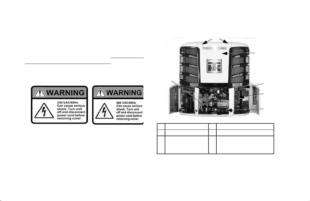
High Voltage Components
Var ious components on the Precedent unit operate using
220/3/60 or 460/3/60 high voltage and are identified by
warning nameplates (examples in Figure 2). All high voltage
wiring is identified by ORANGE conduiting. Be aware of the
locations of these components. Only certified, trained
technicians can service them.
Figure 2: High Voltage Warning
NOTE: See Figure 3 and Figure 4 for high voltage
component locations.
14
1. Condenser Motors 4. High Voltage Control Box
2. Evaporator Motor 5. AC Generator
3. High Voltage
Distribution Box
6. Electric Standby Motor &
Power Receptacle
(SmartPower Option)
Figure 3: High Voltage Component Locations (Front)
Safety Precautions
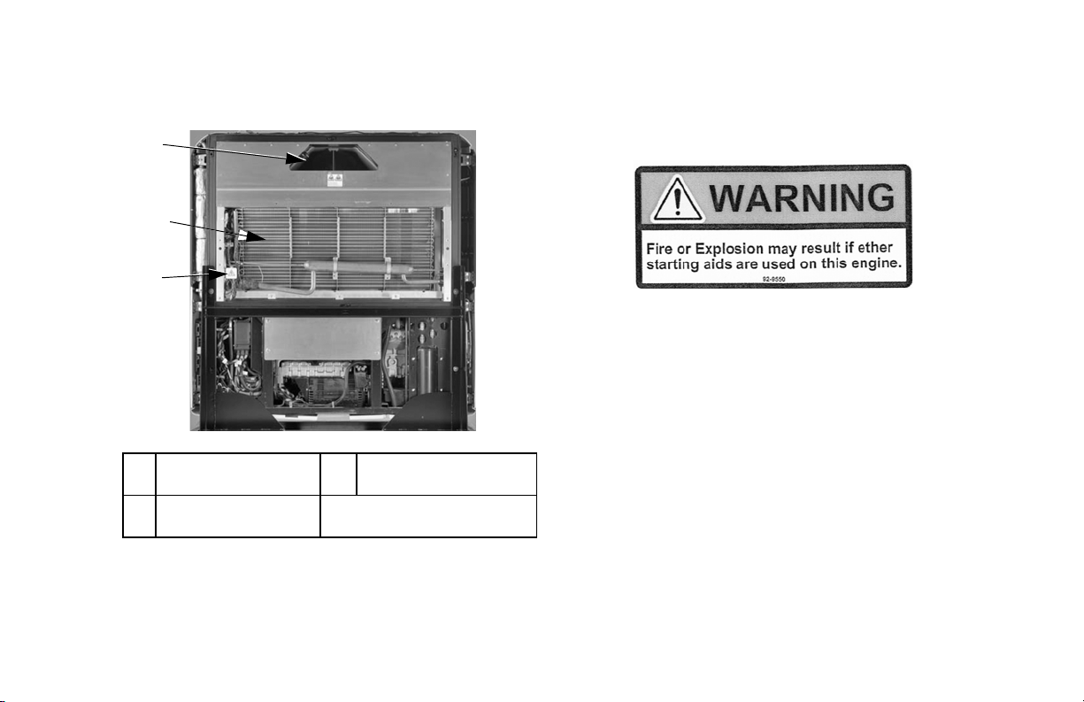
7
8
9
Do Not Use Ether Starting Aids
Figure 5: Do Not Use Ether Starting Aids
(Near Engine)
7. Evaporator Motor 9. High Voltage Junction
8. High Voltage Heater
Strips
Figure 4: High Voltage Component Locations (Rear)
Box
All ORANGE conduiting
contains High Voltage
15

Unit Description
Unit Overview
Thermo King Precedent C-600, S-600 and S-700 are one piece,
self-contained, diesel powered, air cooling/heating units
operating under the control of the SMART REEFER™ 4
(SR-4) programmable microprocessor controller. These units
mount on the front of the trailer with the evaporator extending
through an opening in the front wall. These single temperature
models are designed to maintain temperature in one
compartment or zone.
These units feature all-new DDE (Diesel Direct Electric)
architecture, quiet running Thermo King diesel engine and a
Thermo King reciprocating compressor.
The C-600, S-600 and S-700 are available in the following
models:
Standard : Cooling and heating on die sel engine operation.
SmartPower
engine operation and electric standby operation.
16
TM
Option: Cooli ng and heating on die sel
Figure 6: Front View

Unit Description
Diesel Engine
Precedent C-600, S-600 and S-700 use a 4-cylinder, water
cooled, direct injection diesel engine. The engine is coupled
directly to the compressor on standard units. SmartPower units
are equipped with a centrifugal clutch which transfers power
from the engine to the compressor. Belts transmit power to the
AC generator, water pump, and alternator on all models.
ELC (Extended Life Coolant)
ELC (Extended Life Coolant) is standard equipment. The
maintenance interval for ELC is five years or 12,000 hours. A
nameplate on the coolant expansion tank identifies units with
ELC. The new engine coolant, Chevron Extended Life
Coolant, is RED in color instead of the previous GREEN or
BLUE-GREEN colored conventional coolants.
CAUTION: Do not add “GREEN” or
“BLUE-GREEN” conventional coolant to cooling
systems using “RED” Extended Life Coolant, except
in an emergency. If conventional coolant is added to
Extended Life Coolant, the coolant must be ch anged
after 2 years instead of 5 years.
NOTE: The use of 50/50% pre-mixed ELC is recommended
to assure that de-ionized water is being used. If 100% full
strength concentrate is used, de-ionized or distilled water is
recommended instead of tap water to insure the integrity of
the cooling system is maintained.
EMI 3000
EMI 3000 is an extended maintenance interval package. It is
standard equipment. The EMI 3000 package consists of the
following key components:
• EMI 3000-Hour Cyclonic Air Cleaner Assembly and Air
Cleaner Element
• EMI 5-Micron 3000-Hour Fuel Filter
• EMI 3000-Hour Dual Element Oil Filter
• API Rating CI-4 Mineral Oil
• Five Year or 12,000 Hour ELC (Extended Life Coolant)
The EMI package allows standard maintenance intervals to be
extended to 3,000 hours, or 2 years, whichever occurs first.
NOTE: Units equipped with the EMI 3000 package do
require regular inspection in accordance with Thermo King's
maintenance recommendations.
17

Unit Description
Thermo King Reciprocating
Compressor
The Precedent C-600, S-600 and S-700 are equipped with a
4-cylinder 30.0 cu. in. (492 cm3) displacement Thermo King
X430 reciprocati n g compressor .
Electronic Throttling Valve
The ETV provides enhanced control of the refrigeration system
as follows:
• Allows the refrigeration system to fully utilize the power
capabilities of the engine under varying conditions
• Provides an additional measure of protection against high
discharge pressures
• Protects the engine from high coolant temperature
shutdowns
• Provides a means of precise temperature control.
SMART REEF ER 4 (SR-4) Control
System
The SR-4 is a microprocessor control system designed for
transport refrigeration. The SR-4 integrates the following
functions: changing setpoint and operating mode, viewing
gauge, sensor and hourmeter readings, initiating defrost cycles,
and viewing and clearing alarms.
The microprocessor components are located inside the control
box, which is located inside the lower roadside service door. It
is used to operate the unit. The control panel is mounted on the
face of the control box. It is clearly visible through an opening
in the lower roadside service door.
See “Operating Instructions” for mo re information about the
SR-4 Controller.
Depending on the air temperature in the trailer, as sensed by
the microprocessor Base Controller, the unit will typically
operate in on e of the following modes:
18

Unit Description
Diesel Operation
In diesel operation the microprocessor will select the operating
mode from the following:
• High Speed C ool
• Low Speed Cool
• Low Speed Modulated Cool
• Null (CYCLE-SENTRY operation only)
• Low Speed Modulated Heat
• Low Speed Heat
• High Speed Heat
• Defrost
Electric Operation
In electric operation the microprocessor will select the
operating mode from the following:
• Cool
• Modulated Cool
• Null (CYCLE-SENTRY operation only)
• Modulated Heat (Hot Gas only)
• Hot Gas Heat
• Full Heat (Hot Gas and Electric Heat)
• Defrost (Hot Gas and Electric Heat)
19

Unit Description
CYCLE-SENTRYTM Start-Stop
Controls
WARNING: The unit can start at any time without
warning. Press the O
place the microprocessor On/Off switch in the Off
position before inspecting or servicing any part of the
unit.
The CYCLE-SENTRY Start-Stop fuel saving system provides
optimum operating economy.
When CYCLE-SENTRY Mode is selected the unit will start
and stop automatically to maintain setpoint, keep the engine
warm and the battery charged. When Continuous Mode is
selected, the unit starts automatically and runs continuously to
maintain setpoint and provide constant airflow.
FF key on the control panel and
Data Logging
There are two separate data loggers. The data is downloaded
through the Flash Drive Only USB port on the front of the
control box using a flash drive and ThermoServ™ software.
ServiceWatch™: ServiceWatch is standard equipment. It
records operating events, alarm codes and compartment
temperatures as they occur and at preset intervals. This
information is typically used to analyze unit performance.
CargoWatch™: CargoWatch data logging requires the
installation of optional sensors. Up to six temperature
sensor/probes and four door switches can be installed.
CargoWatch also logs the setpoint. If optional temperature
sensors are installed, their readings are displayed as Datalogger
Sensor (1-6) Temperature in the sensor readings.
USB Ports: :
• The Flash Drive Only USB Port allows a USB Flash Drive
that has been pr operly conf igured us ing the T hermoServ ™
Service Tool to be connected to the unit.
• The optional PC Computer Only USB Port allows a PC
Computer to be connected to the unit via a standard USB
Cable.
20
MICRO
PROCESSOR
ON
OFF
THERMO KING
ON
OFF
POINT
35
SET SENSORSGAUGES
.8
SR4
Smart Reefer 4
°F
35
MENU
USB PORT
FLASH DRIVE ONLY
USB PORT
PC COMPUTER ONLY
1. Flash Drive Only USB Port
2. PC Computer Only USB Port (option)
Unit Description
OptiSet Plus
OptiSet Plus is a grou p o f progr amm able funct io ns tha t cont ro l
how the unit will operate with specific setpoints or named
products. Thi s ass ur es tha t wh en a p art icu lar s etp oin t or n ame d
product is selected, the unit will always operate the same way.
This allows an entire fleet to be configured to match the
1
2
customers’ needs. Contact your Thermo King dealer for
information about programming OptiSet Plus.
FreshSet
FreshSet is included in OptiSet Plus. FreshSet is a demand
base temperature control for fresh products. FreshSet modifies
and adjusts unit airflow operation to control temperature and to
maximize protect ion of car go, whil e keepin g operati ng costs to
a minimum. Contact your Thermo King dealer for information
about programming FreshSet.
Figure 7: HMI Controller and USB Ports
Defrost
Frost gradually builds-up on evaporator coils as a result of
normal operation. Th e unit uses hot re f r ige ra n t to def ro s t th e
evaporator coil. Hot refrigerant gas passes through t he
21
Unit Description
evaporator coil and melts the frost. The water flows through
collection drain tubes onto the ground. The methods of defrost
initiation are Automatic, and Manual.
Automatic Defrost: The SR-4 automatically initiates timed
or demand defrost cycles. The SR-4 microprocessor can be
programmed to initiate timed defrost cycles at intervals of 2, 4,
6, 8, or 12 hours. Demand defrost cycles occur if the
differences between the return air temperature, discharge air
temperature, and coil temperature exceed certain limits. The
unit can enter defrost cycles as often as every 30 minutes if
required.
Manual Defrost: In Manual Defrost mode, the operator
initiates a defrost cycle. See “Initiating a Manual Defrost
Cycle.”
NOTE: The unit will not perform a Manual Defrost Cycle
unless the unit has been turned on with the O
is running in Continuous or CYCLE-SENTRY Mode (or s hut
down in CYCLE-SENTRY Null Mode), and the coil
temperature is below 45 F (7 C).
N key, the unit
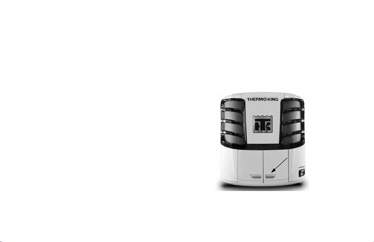
Opening the Front Doors
Pull the right door latch handle out at a 45 degree angle and
turn it down (clockwise) 90 degrees to open the doors and
access the engine compartment. Push the door closed while
holding the door latch handle open and then turn it up
(counterclockwise) 90 degrees to close the door.
Figure 8: Door Latch Location
22

Unit Description
Engine Compartment
The following maintenance items can be checked visually.
WARNING: The unit can start at any time without
warning. Press the O
place the microprocessor On/Off switch in the Off
position before inspecting any part of the unit.
Engine Oil Dipstick: Use the engine oil dipstick to check
the engine oil level.
CAUTION: Make sure the engine is turned off before
attempting to check the engine oil.
FF key on the control panel and
Unit Protection Devices
Coolant Level Switch: The coolant level switch closes if
the coolant level drops below an acceptable level. If it stays
closed for a specified time, the microprocessor records alarm
code 37.
Engine Coolant Temperature Sensor:
The microprocessor uses the engine coolant temperature sensor
to monitor the engine coolant temperature. If the engine
coolant temperature rises above an acceptable level, the
microprocessor records alarm code 41 and possibly 18. The
microprocessor might also shut the unit down.
High Pressure Cutout Switch: The high pressure cutout
switch (HPCO) is located on the compressor discharge
manifold. If the compressor discharge pressure becomes
excessive, the switch opens the circuit to the run relay to stop
the unit. The microprocessor will record Alarm Code 10.
High Pressure Relief Valve: This valve is designed to
relieve excessive pressure in the refrigeration system. It is
located on the receiver tank. If the high pressure relief valve
opens, much of the refrigerant will be lost. Take the unit to a
Thermo King dealer if this occurs.
Low Oil Level Switch: The low oil level switch closes if the
oil drops below an acceptable level. If it stays closed for a
specified time, the microprocessor shuts the unit down and
records Alarm Code 66.
Low Oil Pressure Switch: The low oil pressure switch
closes if the oil pressure drops below an acceptable level. If it
stays closed for a specified time, the microprocessor shuts the
unit down and records alarm code 19.
23

Unit Description
Preheat Buzzer: The preheat buzzer sounds when the base
controller energizes the preheat relay. This warns anyone near
the unit that the controller is about to start the engine.
Overload Relay—Automatic Reset (SmartPower): An
overload relay protects the standby electric motor. The
overload relay opens the circuit to the electric motor if the
motor overloads for any reason (e.g., low line voltage or
improper power supply) while the unit is on electric standby
operation. The microprocessor will record Alarm Code 90.
Smart FETs: Smart FETs in the microprocessor protect some
circuits and components from an overcurrent condition.
Fuses: A number of fuses, located on the microprocessor,
protect various circuits and components. The microprocessor is
located inside the control box.
Fuse Size Function
F1 5A 2A Power for REB
F2 15A On/Off Switch Circuit
F3 40A Fuel Solenoid/Starter Circuit
F4 None2ANo Fuse - All Bosch and Thermo King
Alternators (Note 1)
2A Fuse - All Prestolite Alternators
F5 60A Preheat Circuit (Note 2)
F6 15A High Speed Solenoid Circuit
F7 2A 8X Power for CAN bus
F8 5A 2A Power for CAN bus J12
F10 15A On/Off Relay Circuit
F12 5A 2A Power for CAN bus J13
F13 2A Status Light Circuit
F15 2A SR-4 Power Supply Circuit
F20 2A Alternator Sense Circuit
F25 10A Fresh Air Door Circuit
F25 7.5A High Pressure Cutout Circuit
NOTE: The F5 preheat fuse is a “slow blow” type fuse. It is
designed for use with the Ya nmar trailer engine air
pre-heater. Always replace the fuse with the TK specified
fuse.
24

Manual Pretrip Inspection
Before Starting the Unit
Pretrip inspections are an important part of a preventative
maintenance program designed to minimize operating
problems and breakdowns. Perform this pretrip inspection
before every trip involving refrigerated cargo.
NOTE: Pretrip inspections are not intended to take the place
of regular maintenance inspections.
Fuel: Make sure the diesel fuel supply is adequate to
guarantee engine operation to the next check point. Allow for
maximum fuel consumption of one gallon per hour of engine
operation.
Engine Oil: Check the engine oil level. It should be at the
Full mark when the dipstick is threaded all the way into the oil
pan. Do not overfill.
CAUTION: Turn the engine off before checking the
engine oil level.
Engine Coolant: The engine coolant must have antifreeze
protection to -30 F (-34 C). Add coolant if Alarm Code 37 is
active. Check and add coolant to the expansion tank.
WARNING: Do not remove the expansion tank cap
while the coolant is hot.
Battery: Make sure the battery terminals are tight and free of
corrosion.
Belts: Make sure belts are in good condition and adjusted to
the proper tension. For more information about belt tension,
see the Specifications chapter.
Electrical: Check the electrical connections to make sure they
are securely fastened. Wires and terminals should be free of
corrosion, cracks, and moisture.
Structural: Visually inspect the unit for leaks, loose or
broken part s, and other damage .
25

Manual Pretrip Inspection
Coils: Make sure the condenser and evaporator coils are clean
and free of debris.
Cargo Box: Check the interior and exterior of the cargo box
for damage. Any damage to the walls or insulation must be
repaired.
Cargo Doors: Make sure that the cargo doors and weather
seals are in good condition. The doors should latch securely
and the weather seals should fit tightly.
Defrost Drains: Check the defrost drain hoses to make sure
they are open.
26
Operating Instructions
MICRO
PROCESSOR
ON
OFF
THERMO KING
ON
OFF
Figure 9: SR-4 Control Panel
(Optional PC USB Port Shown)
35
SET SENSORSGAUGES
POINT
.8
SR4
Smart Reefer 4
°F
35
MENU
USB PORT
FLASH DRIVE ONLY
USB PORT
PC COMPUTER ONLY
SMART REEFER 4 (SR-4)
Controller Overview
Thermo King has applied the latest advances in computer
technology to develop a device that controls temperature and
unit function, and displays operating information quickly and
accurately.
There is nothing complicated about learning to operate the
SR-4 Controller, but you will find that a few minutes studying
the contents of this manual will be time well spent.
WARNING: Do not operate the SR-4 until you are
completely familiar with the location and function of
each con t r o l.
27

Operating Instructions
The microprocessor components are located inside the control
box, which is located inside the lower roadside service door.
The microprocessor is connected to a Human Machine
Interface (HMI) Control Panel. It is used to operate the unit.
The USB ports are used to retrieve data from the data logging
system.
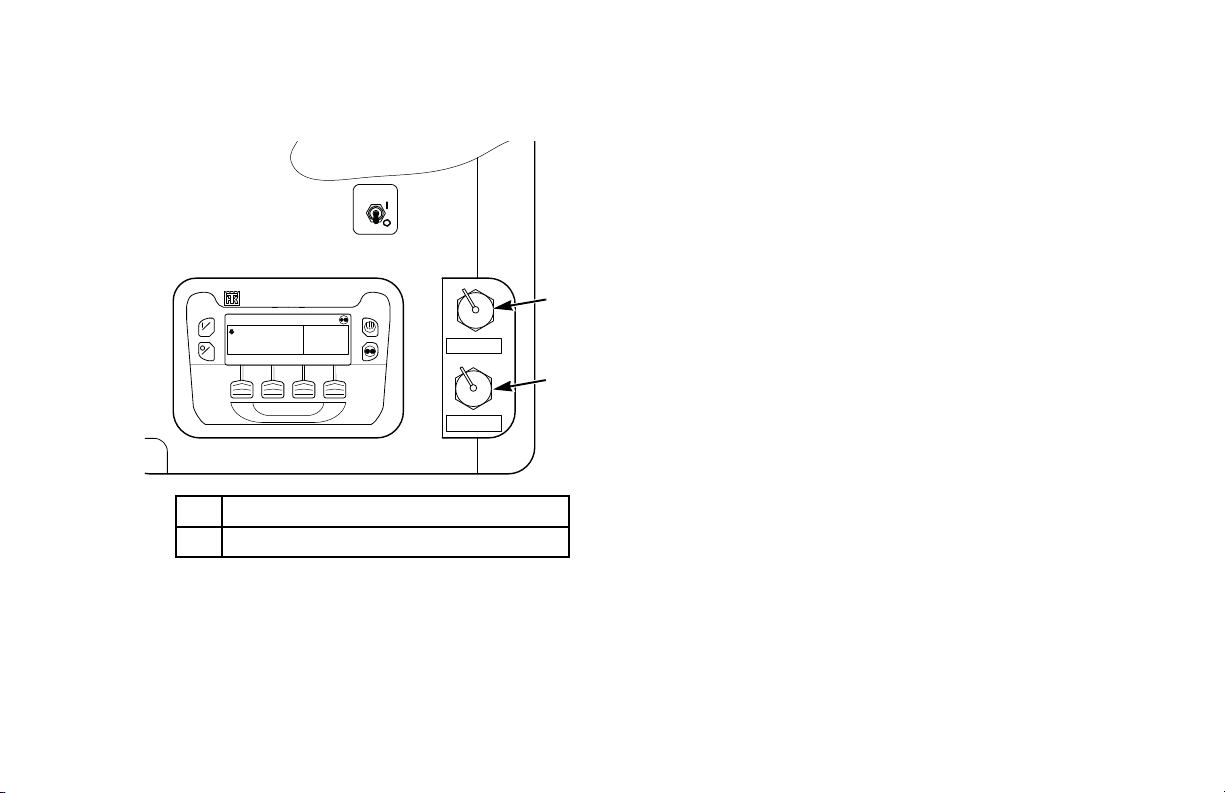
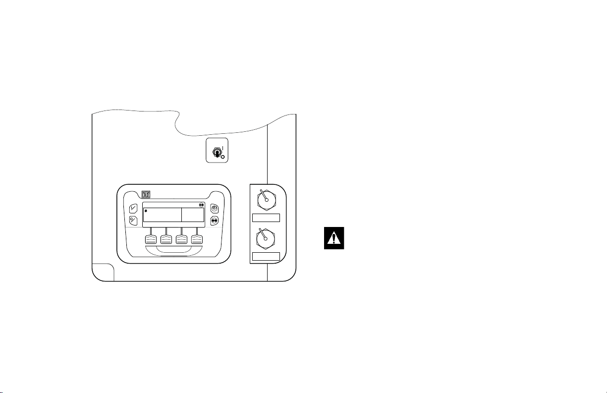
Microprocessor On/Off Switch: This switch supplies or
removes electrical power to the microprocessor. The
Microprocessor Power Switch is located above HMI Control
Panel. It is hidden when the lower roadside body panel
surrounding the Control Box is closed.
WARNING: The unit can start at any time without
warning. Press the O
place the microprocessor On/Off switch in the Off
position before inspecting or servicing any part of the
unit.
FF key on the control panel and
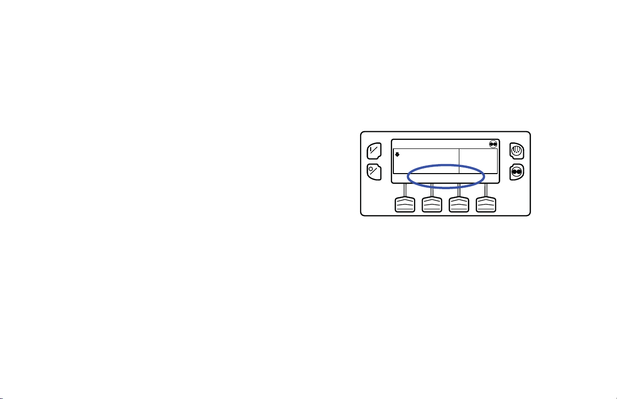
Control Panel
The control panel has a display and eight touch sensitive keys.
The display is capable of showing both text and graphics. The
four keys on the left and right sides of the display are “hard”
(dedicated) keys. The four keys under the display are “soft”
keys. The function of “soft” keys change depending on the
operation being performed. If a soft key is active, its function
will be shown in the display directly above the key.
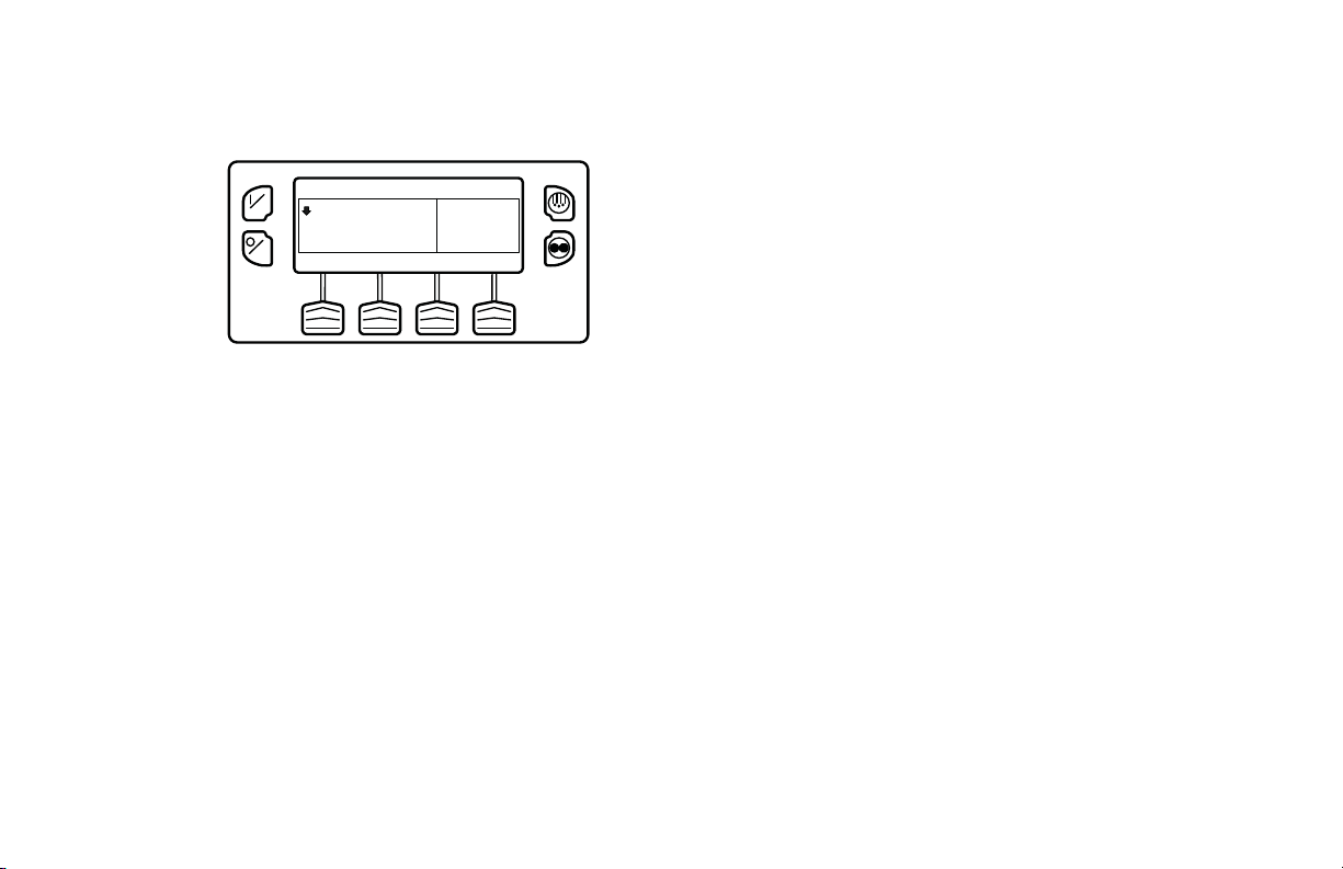
Control Panel Display
The display is used to supply unit information to the operator.
This information includes setpoint, current box temperature
operating information, unit gauge readings, system
temperatures and other information as selected by the operator.
The default display is called the Standard Display. It is shown
in Figure 10 and will be described in detail later in this chapter.
28

THERMO KING
1
2
3
4
5
6
ON
OFF
35
SET SENSORSGAUGES
POINT
Operating Instructions
Display Icons
Display symbols or Icons are used to present additional unit
information
°F
35
.8
MENU
Down-Pointing Arrow: (At the left side of the
display) Shows the unit is cooling. If the arrow
were pointing upward the unit would be heating.
SR4
Smart Reefer 4
CYCLE SENTRY/Continuous Mode Key:
The unit is running in Cycle Sentry Mode as
shown by the C ycle Sent ry Ico n in t he uppe r rig ht
corner of the display. If the Cycle Sentry icon is
1. On Key (Hard Key)
2. Off Key (Hard Key)
3. Display
4. Defrost Key (Hard Key)
5. CYCLE-SENTRY/Continuous Mode Key
(Hard Key)
6. Soft Keys
Figure 10: Control Panel Display and Keys
not present, the unit is running in Continuous
Mode.
USB: The USB Icon in the upper left corner of
the display will appear when a USB device is
connected to either of the USB Ports on the Unit
Control Panel or inside the control box.
29

Operating Instructions
ON
OFF
Hard Keys
The keys on either side of the display are dedicated or “hard”
keys. Their function always remains the same.
On Key: Used to turn the unit on. First the
display will briefly show the Thermo King Logo
and then the statement “Configuring System Please Wait”. When the power-up sequence is
complete the display shows the Standard Display
of box temperature and setpoint.
Off Key: Used to turn the unit off. First the
display will briefly show “System is Powering
Down - Please Wait. Press On to Resume” and
then “Off” will appear momentarily. When the
power-down sequence is complete the display
will be blank. For more information see “Turning
the Unit On and Off” later in this section.
Defrost Key: Press this key to initiate a Manual
Defrost cycle.
CYCLE SENTRY: Used to select Cycle Sentry
Mode or Continuous Mode operation if allowed
by OptiSet Plus. For more information see
“Selecting Cycle Sentry or Continuous Mode”
later in this section.
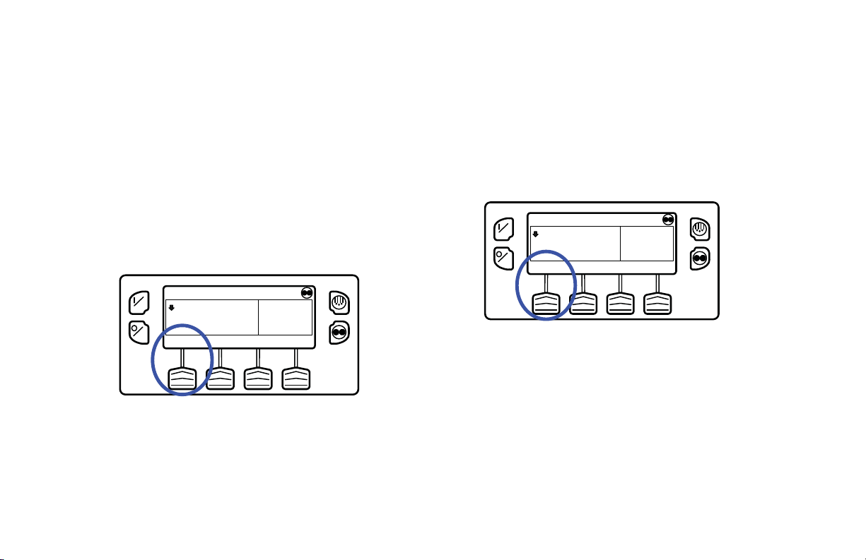
Soft Keys
The four “soft” keys under the display are
multi-purpose keys. Their function changes
depending on the ope ratio n b eing p erf orme d. I f a
soft key is active the key function is shown in the
display directly above the key. The keys are
numbered from le ft to ri ght , wit h Key 1 on t he far
left and Key 4 on the far right.
Typical soft key applications:
•MENU •CLEAR • NO
• NEXT • HOURMETERS • SENSORS
• + OR - • GAUGES • EXIT
• SELECT • BACK • HELP
30

Operating Instructions
Turning Unit On
The unit is turned on by pressing the ON Key (Figure 11) and
off by pressing the OFF Key. When the On Key is pressed the
display briefly sh ows the T HERMO KING Log o as the d isplay
initializes.
IMPORTANT: The ON Key must be held down until the
Thermo King Logo appears. If the ON Key is not held down
long enough (approximately ½ second), the display may
flicker but the unit will not start up. If this occurs, hold the
ON Key down until the Thermo King logo appears.
NOTE: With extremely cold ambient temperatures it may
take up to 15 seconds for the display to appear on initial
startup.
ON
OFF
Figure 11: ON Key
Then the startup screen (Figure 12) appears while
communications are established and the unit prepares for
operation.
ON
OFF
CONFIGURING SYSTEM
PLEASE WAIT
Figure 12: Startup Screen
31

Operating Instructions
If a Flash Drive is Connected:
If a properly configured USB Flash Drive is inserted in the
Flash Drive Only USB Port on the Control Panel when the unit
is turned on, the display (Figure 13) will briefly show FLASH
DRIVE.
ON
OFF
FLASH DRIVE DETECTED
EXIT DOWN FLASH OPTISET
LOAD LOAD PLUS
ON
FLASH DRIVE
Figure 14: Flash Drive Menu
OFF
IMPORTANT: The engine start is not delayed by the Flash
Drive Menu shown above. The engine start prompt will
appear and the engine will start. After the engine is started
the display will return to the Flash Drive Menu or the
Figure 13: Flash Drive
Then FLASH DRIVE DETECTED and the Flash Drive Menu
will appear on the display (Figure 14). The display will be
shown for about 30 seconds and then the Standard Display will
appear. To go to the Standard Display immediately press the
EXIT Soft Key.
32
Standard Display.
If a properly configured USB Flash Drive is connected to the
USB Flash Drive connector, this feature allows the operator to
select the desired Flash Drive function. If enabled when the
Flash Drive was configured, the following functions may be
available:
Operating Instructions
• DOWNLOAD
• “Download the ServiceWatch Data Logger
• “Download the CargoWatch Data Logger
• FLASHLOAD
• “Flash load Base Controller Software
• “Flash load HMI Control Panel Software
• OPTISET PLUS
•SEND
• “Send OptiSet Plus files
• RETRIEVE
• “Retrieve OptiSet Plus files
The Flash Drive is also available from the Main Menu.
The Flash Drive Menu will time out about 30 seconds after the
engine starts. When the Flash Drive Menu times out, the
Standard Display will appear. To go to the Standard Display
immediately press the EXIT Key.
Configurable Soft Keys
When the Standard Display is shown, the default functions of
the two center soft keys are GAUGES and SENSORS.
(Figure 15)
ON
OFF
35
SET SENSORSGAUGES
POINT
Figure 15: Soft Keys
The functions of these two keys can be changed as required for
customer convenience. The functions of these two soft keys on
the Standard Display can be re-assigned to any of the following
functions using the Guarded Access > Main Menu
Configuration menu:
Gauges Pretrip SOT (start of trip)
Sensors Data Logger Hourmeters
°F
35
.8
MENU
33

Operating Instructions
The GAUGES and SENSORS functions are always available
from the Maintenance Menu.
In the example show n in F igure 16 , t he so ft ke y fu ncti ons f rom
the Standard Display have been changed to PRETRIP and SOT
(Start of Trip marker). The GAUGES and SENSORS functions
are always available from the Maintenance Menu.
ON
OFF
35
SET SOTPRETRIP
POINT
°F
35
.8
MENU
Figure 16: PRETRIP and SOT
Display Heater
The HMI Control Panel is equipped with a display heater. This
heater is needed to make the display visible in very cold
ambient temperatures.
The HMI has its own internal temperature sensor for the
display heater. The heater is energized when the unit is turned
on and the ambient temperature is below 29.4 F (-2 C). The
heater turns off when the temperature sensed by the internal
sensor rises above 37.4 F (+3 C). The heater draws from 1.4 to
1.7 amps when energized.
The colder the ambient temperature the longer it will take for
the heater to make the display visible on a cold startup. It may
take 10-15 seconds for the display to appear with extremely
cold temperatures.
If a Language is Enabled
If more than one language has been enabled from the Guarded
Access Language Menu, a prompt will appear to allow the
desired langua ge to be c hosen as s hown be low. Only languages
specifically enabled from the Guarded Access Menu are
available. If a different language is desired, press the NO Key
(Figure 17).
IMPORTANT: The engine start is not delayed by the
language prompt shown below. The prompt will appear for 10
seconds and then the engine will start. After the engine is
started the display will return to the prompt shown.
34

Operating Instructions
The display will briefly show PROGRAMMING
ON
CURRENT LANGUAGE IS
ENGLISH
LANGUAGE - PLEASE WAIT in the new language as shown
in Figure 19.
OFF
OK?
YES NO
Figure 17: NO Key
The Language menu will appear as shown in Figure 18. Press
the + or - Keys to select the desired language. When the
desired language is shown press the YES Key to confirm the
choice.
Figure 18: + or -, then YES Key
Figure 19: New Language
The new language is conf irme d, and then t he S tan dar d Displ ay
will appear in the new language as shown in Figure 20. The
unit is ready to run.
Figure 20: Standard Display, New Language
35

Operating Instructions
If Log Alarms are Present
Log Alarms are indicated for 60 seconds each time the unit is
turned on. This level of alarm serves as a notice to take
corrective action before a problem becomes severe.
Maintenance items such as maintenance hourmeter time-outs
are log alarms. The Temperature Watch screen is not disabled
if only log alarm(s) are active.
If log alarm(s) are present the Log Alarm notice shown in
Figure 21 will appear on the display for 60 seconds. The
remote indicator alarm light (if installed) will also be on during
this period. After 60 seconds the Standard Display will appear
and the remote indicator alarm light will go off. Pressing the
EXIT soft key (Figure 21) will return to the Standard Display
immediately.
ON
OFF
Figure 21: Log Alarms Active
LOG ALARMS ACTIVE
GO TO MENU TO VIEW
EXIT
NOTE: The Alarm Icon does not app e ar on startup with log
alarms present.
When the unit is ready to run the Standard Display
appears(Figure 22).
ON
OFF
35
SET SENSORSGAUGES
POINT
°F
35
.8
MENU
Figure 22: Standard Display
36

Operating Instructions
Turning The Unit Off
Pressing the OFF Key stops unit operation. The unit shuts
down immedia tely and the displa y briefly shows the power
down message (Figur e 23).
SYSTEM IS POWERING DOWN
ON
OFF
Figure 23: Power Down Message
The Standard Display
The Standard Display is the default display that appears if no
other display function is selected. The Standard Display shows
the box temperature and setpoint. The box temperature is that
measured by the controlling sensor, usually the return air
sensor. The box temperature in Figure 25 is 35.8 F (2.1 C) with
a 35 F (1.7 C) setpoint.
ON
OFF
35
SET SENSORSGAUGES
POINT
°F
35
.8
MENU
The display briefly shows OFF (Fig ur e 24) and the n goes
blank. To start the unit again, press the ON Key.
Figure 25: Standard Display
ON
OFF
OFF
The down-pointing arrow at the left side of the
display shows the unit is cooling. If the arrow
were pointing upward the unit would be heating.
Figure 24: Display Shows OFF
37

Operating Instructions
The unit is running in Cycle Sentry Mode as
shown by the Cycle Sen try Ic on in t he uppe r r ight
corner of the display. If the Cycle Sentry icon is
not present, the unit would be running in
Continuous Mode.
The USB Icon in the upper left corner of the
display will appear when a USB Flash Drive is
connected to the Flash Drive Only USB Port on
the unit control panel or a PC computer is
connected to the PC Only USB Port on the Unit
Control Panel.
Pressing the left soft key allows the user to change the
SETPOINT, and pressing th e right soft key accesses the MAIN
MENU. The other two soft keys access the GAUGES menu
and the SENSORS menu.
NOTE: The functions of the GAUGES and SENSORS soft
keys may be re-assigned to better suit customer requirements.
The GAUGES and SENSORS functions are always available
from the Maintenance Menu.
The TemperatureWatch Display
The TemperatureWatch Display appears 2 ½ minutes after the
Standard Display appears so long as there is no key activity
and no check, prevent or shutdown alarms are present. The
TemperatureWatch Display will remain on until any key is
pressed or a check, prevent or shutdown alarm occurs.
The TemperatureWatch Display shows the box temperature
and setpoint. The large numbers allow unit conditions to be
checked from a distance. The box temperature is that measured
by the controlling sensor, usually the return air sensor . The box
temperature in Figure 26 is 35.8 F (2.1 C) with a 35 F (1.7 C)
setpoint. The Cy cle Se ntry i con in the uppe r righ t corn er of the
display shows that the unit is operating in Cycle Sentry mode.
If the Cycle Sentry icon is not present, the unit is running in
Continuous Mode. The down-pointing arrow indicates that the
unit is cooling. Pressing any soft key returns the display to the
Standard Display.
38

Operating Instructions
MENU
35
°F
35
TEMPERATURE SETPOINT
.8
ON
OFF
Changing The Setpoint
The Setpoint is changed from the Standard Display. If the
TemperatureWatch display is present, press any key to return to
the Standard Display.
IMPORTANT: If OptiSet Plus is in use there are several
possible options when changing the setpoint.
Figure 26: TemperatureWatch Display
If an alarm condition (other than a log alarm) is present, the
TemperatureWatch Display will not appear. If an alarm
condition occurs while the TemperatureWatch Display is
present the display will return to the Standard Display to
indicate that an alarm condition has occurred.
If the Defrost Key or Cycle Sentry Key is pressed, the display
will return to the TemperatureW atch Display immediately after
the defrost cycle is initiated or the operating mode is changed.
Numerical Setpoints
If OptiSet Plus is not in use or if only Numerical Setpoints are
enabled the left soft key will be labeled SETPOINT (Figure
27).
ON
OFF
35
SET SENSORSGAUGES
POINT
Figure 27: Setpoint
°F
35
.8
MENU
39
Operating Instructions
Named Products - OptiSet Plus
OptiSet Plus allows the use of Named Products such as
APPLES or BANANAS in place of a numerical setpoint. If
only named products are enabled the left soft key will be
labeled PRODUCT (Figure 28).
• A single setpoint temperature may be allowed for the
specific named product.
• A numerical setpoint range may be all owe d fo r t he
specific named product.
ON
OFF
35
PRODUCT SENSORSGAUGES
Figure 28: Left Soft Key Labeled “Product”
°F
35
.8
MENU
Both Numerical Setp oint s a nd Named
Products
OptiSet Plus can allow the use of both Numerical Setpoints and
Named Products. If both numerical setpoints and named
products are enabled the left soft key will be labeled
PRODUCT/SETPOINT (Figure 29).
ON
OFF
35
PRODUCT/ SENSORSGAUGES
SETPOINT
Figure 29: Left Soft Key Labeled
“PRODUCT/SETPOINT”
°F
35
.8
MENU
40

Changing the Setpoint - Numerical
-
NO
NEW SETPOINT WILL BE
40 F
+
+/- TO CHANGE OK?
YES
Setpoint
If the Temperature Watch display is shown, press any soft key
to return to the Standard Display. From the Standard Display,
press the SETPOINT Key (Setpoint Key
The setpoint display appears (Figure 30).
Operating Instructions
ON
OFF
+/- TO CHANGE
-
CURRENT SETPOINT
35 F
+
EXIT
ON
OFF
Figure 31: Setpoint Changed Using “+” Key
The YES and NO Keys (Figure 32) confirm the setpoint
change. When the desired setpoint has been selected using the
“+” and/or “-” Keys, press the YES Key to confirm and load
the new setpoint. If the setpoint is changed using the “+” or “-”
Keys, the change must be confirmed or rejected by pressing the
Figure 30: Setpoint Display
YES or NO Key wi th i n 10 seconds of cha ng ing t h e se tp oi nt. A
warning beep will sound for 5 seconds as a reminder.
The “-” and “+” Keys are used to increase or decrease the
setpoint until the desired setpoint is shown. In Figure 31 the
setpoint has been changed to 40 F using the “+” Key.
Failure to confirm the new setpoint by pressing Yes or No
within 10 seconds of changing the setpoint will result in no
setpoint change. In addition, Alarm Code 127 Setpoint Not
Entered is set, to indicate that a setpoint change was initiated
but not completed.
41

Operating Instructions
ON
OFF
NEW SETPOINT WILL BE
40 F
+/- TO CHANGE OK?
-
YES
+
NO
Figure 32: Yes and No Keys
After the YES K ey has been pressed, the display br i e fly shows
PROGRAMMING NEW SETPOINT - PLEASE WAIT. The
display then confirms the new setpoint for several seconds
(Figure 33):
ON
NEW SETPOINT IS
40 F
OFF
Figure 33: New Setpoint
If the NO Key is pressed the display will briefly show
SETPOINT NOT CHANGED and return to the Standard
Display. The Standard Display will show the old setpoint.
The display then returns to the Standard Display showing the
new setpoint. Notice in Figure 34 that the arrow now points up
to indicate that the unit is heating.
ON
OFF
35
SET SENSORSGAUGES
POINT
°F
40
.8
MENU
Figure 34: Up Arrow
IMPORT ANT: If the setpoint is changed using the “+” or “-”
Keys, the change must be confirmed or rejected by pressing
the YES or NO Key within 10 seconds of changing the
setpoint.
42

• If the YES Key is pressed, the setpoint change made with
the “+” or “-” Key is accepted, the setpoint changes, and
the display returns to the Standard Display.
• If the NO Key is pressed the setpoint change made with
the “+” or “-” Key is not accepted, the setpoint is not
changed, and the display returns to the Standard Display.
• If the YES or NO Key is not pressed within 10 seconds of
making a change with the “+” or “-” Key, the setpoint is
not changed and the display returns to the Standard
Display. The display briefly shows [SETPOINT NOT
CHANGED] and Alarm Code 127 Setpoint Not Entered is
set, to indicate that a setpoint change was initiated but not
completed.
See Figur e 35 fo r a n overview of the Changing the Setpoint -
Numerical Setpoint procedure.
Operating Instructions
43

Operating Instructions
44
ON
OFF
Setpoint Key
ON
OFF
35
SET SENSORSGAUGES
POINT
+/- TO CHANGE
-
°F
.8
CURRENT SETPOINT
35 F
+
35
MENU
EXIT
ON
OFF
+ or - Keys
ON
OFF
NEW SETPOINT WILL BE
40 F
+/- TO CHANGE OK?
-
YES
+
NEW SETPOINT WILL BE
40 F
+/- TO CHANGE OK?
-
YES
+
NO
NO
ON
OFF
New Setpoint
ON
OFF
POINT
Yes or No Keys
Figure 35: Changing the Setpoint - Numerical Setpoint
NEW SETPOINT IS
35
SET SENSORSGAUGES
40 F
.8
°F
40
MENU

Operating Instructions
Changing the Setpoint - Named
Product
If the Temperature Watch display is shown, press any soft key
to return to the Standard Display. From the Standard Display,
press the PRODUCT Key.
Note that PRODUCT is displayed in place of SETPOINT
(Figure 36).
ON
OFF
Figure 36: Product Displayed
The display briefly shows PRODUCT and then the setpoint
display appears (Figure 37).
GRAPEFRUIT, ARIZONA
59
PRODUCT SENSORSGAUGES
°F
59
.8
MENU
ON
OFF
CURRENT PRODUCT IS
GRAPEFRUIT, ARIZONA
+/- TO CHANGE
-
+
EXIT
Figure 37: Setpoint Display
The “-” and “+” Keys are used to change the Named Product
until the desired product is shown. In Figure 38 the product has
been changed to Potato, Late Crop.
ON
OFF
NEW PRODUCT WILL BE
POTATO, LATE CROP
+/- TO CHANGE OK?
-
YES
+
NO
Figure 38: Named Product
45

Operating Instructions
The YES and NO Keys confirm the product change (Figure
39). When the desired product has been selected using the “+”
and/or “-” Keys, press the YES Key to confirm and load the
new product. If the product is changed using the “+” or “-”
Keys, the chan ge must be conf irmed or re jected b y pres sing th e
YES or NO Key within 10 secon ds of changing the product. A
warning beep will sound for 5 seconds as a reminder.
Failure to confirm the new product by pressing Yes or No
within 10 seconds of changing the product will result in no
product change. In addition, Alarm Code 127 Setpoint Not
Entered is set, to indicate that the product change was initiated
but not completed.
ON
OFF
NEW PRODUCT WILL BE
POTATO, LATE CROP
+/- TO CHANGE OK?
-
YES
+
NO
Figure 39: Yes and No Keys
After the YES Key has been pressed, the display briefly shows
PROGRAMMING NAMED PRODUCT - PLEASE WAIT.
The display then confirms the new setpoint for several
seconds.
ON
OFF
NEW NAMED PRODUCT IS
POTATO, LATE CROP
Figure 40: New Named Product
If the NO Key is pressed the display will briefly show
SETPOINT NOT CHANGED and return to the Standard
Display. The Standard Display will show the old setpoint.
The display then returns to the Standard Display showing the
new named product. Notice that the arrow points down, to
indicate that the unit is cooling (Figure 41).
46
ON
OFF
POTATO, LATE CROP
45
PRODUCT SENSORSGAUGES
°F
45
.8
MENU
Figure 41: Standard Display
IMPORTANT: If the named product is changed using the
“+” or “-” Keys, the change must be confirmed or rejected by
pressing the YES or NO Key within 10 seconds of changing
the named product.
• If the YES Key is pressed, the product change made with
the “+” or “-” Key is accepted, the product changes, and
the display returns to the Standard Display.
• If the NO Key is pressed the product change made with
the “+” or “-” Key is not accepted, the product is not
changed, and the display returns to the Standard Display.
Operating Instructions
• If the YES or NO Key is not pressed within 10 seconds of
making a change with the “+” or “-” Key, the product is
not changed and the display returns to the Standard
Display. The display briefly shows [SETPOINT NOT
CHANGED] and Alarm Code 127 Setpoint Not Entered is
set, to indicate that the product change was initiated but
not completed.
See Figure 42 for an overview of the Changing the Setpoint -
Named Product procedure.
47

Operating Instructions
48
ON
OFF
PRODUCT SENSORSGAUGES
Product Key
ON
+/- TO CHANGE
OFF
GRAPEFRUIT, ARIZONA
°F
.8
59
CURRENT PRODUCT IS
GRAPEFRUIT, ARIZONA
-
+
Setpoint Display
59
MENU
ON
OFF
NEW PRODUCT WILL BE
POTATO, LATE CROP
+/- TO CHANGE OK?
-
YES
+
NO
+ or - Keys
ON
EXIT
OFF
NEW PRODUCT WILL BE
POTATO, LATE CROP
+/- TO CHANGE OK?
-
YES
+
NO
If Yes Key Chosen,
Y es or No Keys
Figure 42: Changing the Setpoint, Named Product
ON
OFF
ON
OFF
NEW NAMED PRODUCT IS
POTATO, LATE CROP
POTATO, LATE CROP
45
PRODUCT SENSORSGAUGES
Standard Display
New Named Product
°F
45
.8
MENU

Operating Instructions
Changing the Setpoint - Both
Numerical Setpoint and Named
Product Available
If the Temperature Watch display is shown, press any soft key
to return to the Standard Display. From the Standard Display,
press the SETPOINT Key. Note that both PRODUCT and
SETPOINT are displayed as shown (Figure 43).
ON
OFF
35
PRODUCT/ SENSORSGAUGES
SETPOINT
Figure 43: PRODUCT and SETPOINT are displayed
The NAMED PRODUCT / NUMERIC SETPOINT prompt
will appear as shown (Figure 44).
°F
35
.8
MENU
.
ON
OFF
NAMED PRODUCT / NUMERIC
SETPOINT?
EXIT NAMED NUMERIC
Figure 44: NAMED PRODUCT / NUMERIC
SETPOINT Prompt
• Press the NUMERIC Soft Key to proceed with Changing
the Setpoint - Numeric Setpoint change as previously
shown.
• Press the NAMED Soft Key to proceed with Changing the
Setpoint - Named Product change as shown previously.
• Press the EXIT Soft Key to return to the Standard Display .
49

Operating Instructions
Starting the Diesel Engine
Diesel engine preheats and starts are automatic in both
Continuous Mode and Cycle Sentry Mode. The engine will
preheat and start as required when the unit is turned on. The
engine preheat and start will be delayed in Cycle Sentry mode
if there is no current need for the engine to run. If any keys are
being pressed on the HMI Control Panel the engine will not
preheat and start until 10 seconds after the last key is pressed.
NOTE: If the unit is equipped with optional Electric Standby
there may be some additional prompts before the engine will
start. See STARTING THE ELECTRIC MOTOR on the
following pages for details.
CAUTION: The engine may start automatically any time the
unit is turned on.
WARNING: Never use starting fluid.
When the engine is preparing to start the HMI Control Panel
will display the engine start screen (Figure 45). The preheat
buzzer sounds during the engine preheat and crank sequence.
ON
DIESEL ENGINE STARTING
OFF
Figure 45: Engine Start Screen
After the engine is started the display returns to the Standard
Display of temperature and setpoint.
Starting the Electric Motor
Units equipped with the SmartPower option only.
Electric Power Receptacle: The electric power receptacle
is used to connect the unit to an appropriate electric power
source for electric standby operation (Figure 46). The electric
power receptacle is usually mounted on the trailer below the
HMI Control Panel. Make sure the unit and the power supply
are turned off before connecting or disconnecting a power
cord.
50

Electric motor starting is automatic in both Continuous Mode
and Cycle Sentry Mode. The motor will start as required when
the unit is turned on. If any keys are being pr e ssed on the HMI
Control Panel prior to the motor start, the motor start will be
delayed until 10 seconds after the last key is pressed.
CAUTION: The motor may start automatically any time the
unit is turned on.
Figure 46: Electric Power Receptacle
When the motor is preparing to start the HMI Control Panel
will display the motor start screen (Figure 47). The preheat
buzzer sounds for 20 seconds before the electric motor starts.
Operating Instructions
ON
ELECTRIC MOTOR STARTING
OFF
Figure 47: Motor Start Screen
Switching from Diesel to Electric
Units equipped with the SmartPowerTM option only.
If the Diesel to Electric Auto-Switch Enabled feature in
Guarded Access is set YES then the unit will automatically
switch to Electric Mode operation when standby power is
connected and available.
If the Diesel to Electric Auto-Switch Enabled feature in
Guarded Access is set NO then the prompt screen (Figure 48)
will appear when standby power is connected and available.
51

Operating Instructions
ON
OFF
ELECTRIC STANDBY DETECTED
DO YOU WISH TO SWITCH TO
Figure 48: Standby Power Connected
ELECTRIC?
Electric Mode operation will briefly be confirmed. If unit
operation is required the electric motor will start as shown
previously under STARTING THE ELECTRIC MOTOR.
If the Diesel to Electric Auto-Switch Enabled feature in
NOYES
Guarded Access is set NO then the unit can also be switched
from Diesel mode to Electric mode operation using the Electric
Standby Selection from the Main Menu as shown later in this
section.
If NO is selected, then the unit will continue to operate in
Diesel Mode. If YES is selected then the display will briefly
show the screen in Figure 49.
ON
OFF
PROGRAMMING ELECTRIC
STANDBY
PLEASE WAIT
Figure 49: YES Selected
52
Switching from Electric to Diesel
Units equipped with the SMARTPOWER option only.
If the Electric to Diesel Auto-Switch Enabled feature in
Guarded Access is set YES then the unit will automatically
switch to Diesel Mode operation when standby power is turned
off or is no longer available.
If the Electric to Diesel Auto-Switch Enabled feature in
Guarded Access is set NO and standby power is discon nected
or fails, the unit will not automatically switch to Diesel mode.
This is primarily designed to prevent unauthorized diesel
engine starts when the truck is indoors or on a ferry where
engine operation is strictly prohibited. If the Electric to Diesel

Operating Instructions
Auto-Switch Enabled feature in Guarded Access is set NO then
the prompt screen (Figure 50) will appear when standby power
is turned off or is no longer available.
ON
OFF
ELECTRIC STANDBY NOT DETECTED
DO YOU WISH TO SWITCH TO
DIESEL?
YES NO
Figure 50: Standby Power is Off
If YES is selected then the display will briefly show the screen
in Figure 51.
PROGRAMMING DIESEL MODE
ON
OFF
PLEASE WAIT
Figure 51: Yes Selected
Diesel Mode operation will briefly be confirmed. If unit
operation is required the diesel engine will start as shown
previously under STARTING THE DIESEL ENGINE.
If the Electric to Diesel Auto-Switch Enabled feature in
Guarded Access is set NO then the unit can also be switched
from Diesel mode to Electric mode operation using the Diesel
Selection from the Main Menu as shown later in this section.
Initiating a Manual Defrost Cycle
Defrost cycles are usually initiated automatically based on time
or demand. Manual defrost is also available
Manual defrost is available if the unit is running and the
evaporator coil temperature is less than or equal to 45 F (7 C).
NOTE: If the Rail Alternate feature is set YES defrost is
allowed with an evaporator coil temperature less than or
equal to 55 F (13 C).
Other features such as door switch settings may not allow
manual defrost under some conditions. To initiate a manual
defrost cycle, press the Defrost Key (Figure 52).
53
Operating Instructions
ON
OFF
35
SET SENSORSGAUGES
POINT
°F
35
.8
MENU
Figure 52: Press Defrost Key
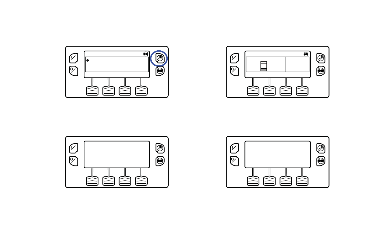
The display briefly shows [DEFROST], [PROGRAMMING
DEFROST - PLEASE WAIT] and then [DEFROST
STAR T E D ] ( F i g ur e 53).
ON
OFF
DEFROST STARTED
Figure 53: Defrost Started
The display then shows the Defrost display. The bar indicator
shows approximately how much time remains to complete the
defrost cycle. The bar indicator shows that the defrost cycle is
about 25% complete (Figure 54).
54
ON
35
OFF
POINT
Figure 54: Bar Indicator
If conditions do not allow a defrost cycle, the display shown in
Figure 55 will briefly appear. The display will then return to
the Standard Display.
ON
OFF
DEFROST NOT AVAILABLE
Figure 55: Defrost Not Available
See Figure 56 for an overview of the Initiating a Manual
Defrost Cycle procedure.
MENUSET SENSORSGAUGES

Operating Instructions
OFF
ON
SET SENSORSGAUGES
POINT
35
°F
35
.8
MENU
ON
OFF
DEFROST STARTED
Yes
ON
OFF
POINT
35
MENUSET SENSORSGAUGES
DEFROST NOT AVAILABLE
ON
OFF
No
Figure 56: Initiating a Manual Defrost Cycle
55
Operating Instructions
Terminating a Defrost Cycle
The defrost cycle terminates automatically when the coil
temperature is greater than or equal to 58 F (14 C) or the
defrost timer expires. Defrost can also be terminated by turning
the unit off and back on.
NOTE: If Rail Alternate is set YES the defrost cycle
terminates at 70 F (21 C) or if the defrost timer expires.
Selecting Cycle Sentry or
Continuous Mode
When Cycle Sentry Mode is selected the unit will start and stop
automatically to maintain setpoint, keep the engine warm and
the battery charged. When Continuous Mode is selected, the
unit starts automatically and runs continuously to maintain
setpoint and provide constant airflow.
IMPORTANT: Cycle Sentry or Continuous Mode may not be
selectable if OptiSet Plus is in use.
See Figure 62 for an overview of the Selecting Cycle Sentry
or Continuous Mode procedure.
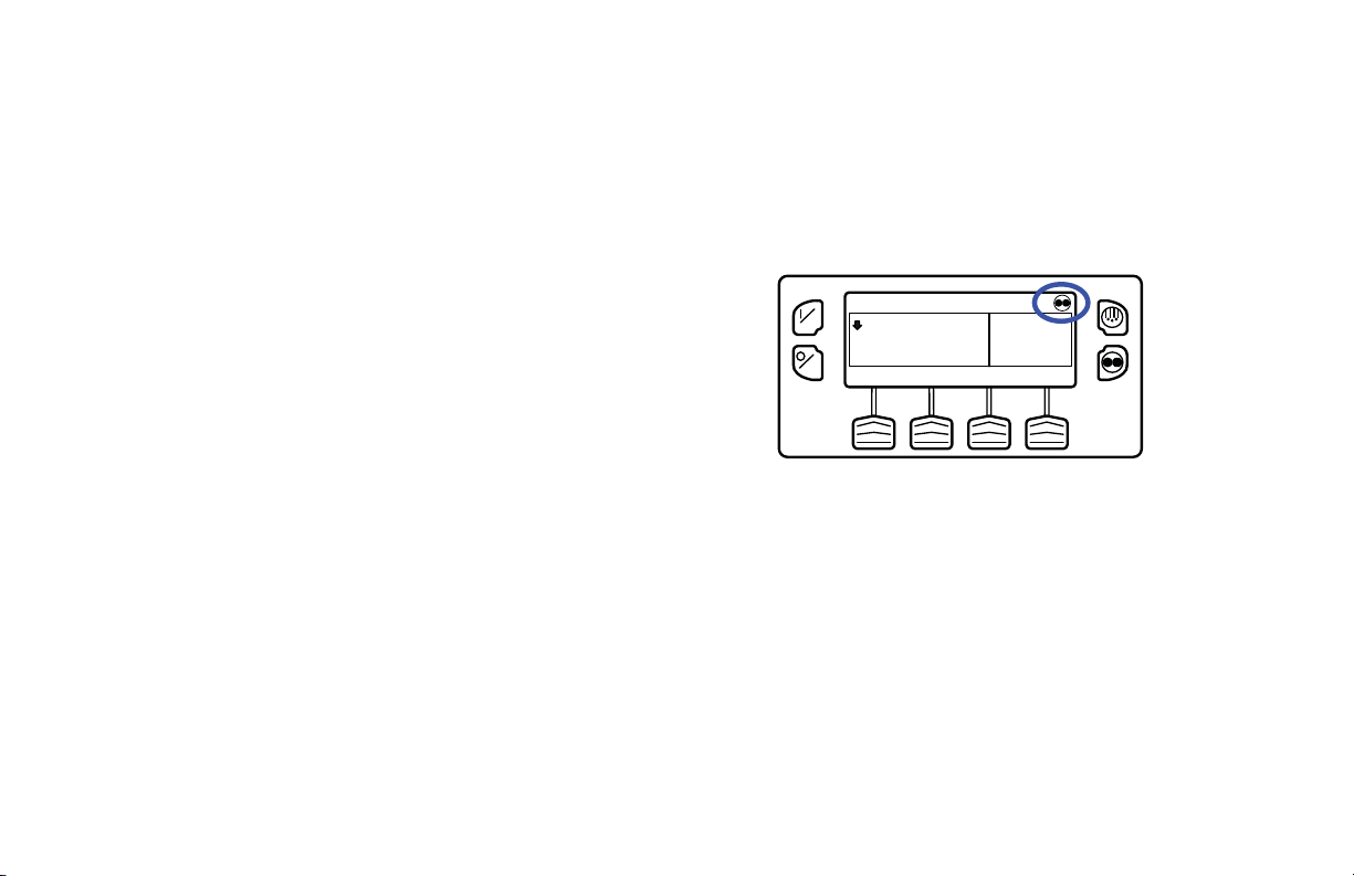
If the unit is operating in Cycle Sentry Mode, the Cycle Sentry
Icon will be present in the upper right corner of the display as
shown below. If the Cycle Sentry Icon (Figure 57) is not
present the unit is operating in Continuous Mode.
ON
OFF
35
SET SENSORSGAUGES
POINT
°F
35
.8
MENU
Figure 57: Cycle Sentry Icon
If allowed by OptiSet Plus, Cycle Sentry Mode or Continuous
Mode is selected by pressing the Cycle Sentry/Continuous Key
as shown in Figure 58.
56
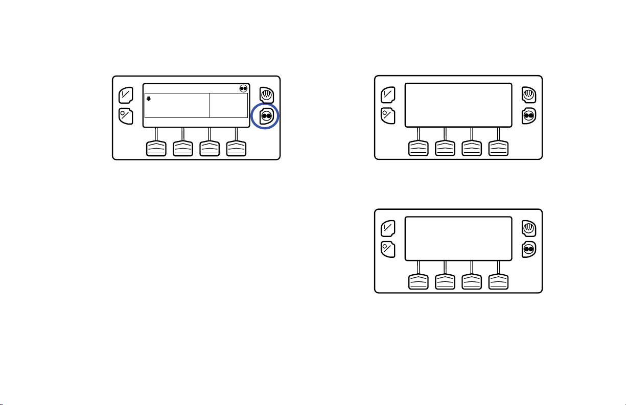
ON
OFF
35
SET SENSORSGAUGES
POINT
Operating Instructions
PROGRAMMING CONT MODE
°F
35
.8
MENU
ON
OFF
PLEASE WAIT
Figure 58: Cycle Sentry/Continuous Key
NOTE: Cycle Sentry Mode or Continuous Mode can also be
selected using the Main Menu > Mode Submenu.
If the unit is in Cycle Sentry Mode, pressing the Cycle
Sentry/Continuous Key changes the mode from Cycle Sentry
Mode to Continuous Mode. The display confirms the change,
as shown in Figure 59.
Figure 59: Continuous Mode
The new mode is confirmed for 3 seconds (Figure 60).
ON
OFF
NEW SYSTEM MODE IS
CONTINUOUS
Figure 60:New Mode Confirmed
57

Operating Instructions
The display then returns to the Standard Display. In the
example shown in Figure 61 the absence of the Cycle Sentry
Icon indicates that the unit is running in Continuous Mode.
ON
OFF
35
SET SENSORSGAUGES
POINT
°F
35
.8
MENU
Figure 61: Cycle Sentry Icon Not Shown =
Continuous Mode
Pressing the Cycle Sentry/Continuous Key again allows the
operator to change back to Cycle Sentry Mode operation.
IMPORTANT: If the unit is in Cycle Sentry Null and the
mode is switched to Continuous Mode, the unit will start
automatically.
IMPORTANT: Cycle Sentry or Continuous Mode may not be
selectable if OptiSet Plus is in use.
58

Operating Instructions
ON
OFF
SET SENSORSGAUGES
POINT
35
°F
35
.8
MENU
PROGRAMMING CONT MODE
ON
OFF
PLEASE WAIT
OFF
ON
SET SENSORSGAUGES
POINT
35
°F
35
.8
MENU
Continuous Mo de
ON
OFF
SET SENSORSGAUGES
POINT
35
°F
35
.8
MENU
Selected
ON
OFF
NEW SYSTEM MODE IS
CONTINUOUS
Figure 62: Selecting Cycle Sentry or Continuous Mode
59

Operating Instructions
Using the Gauges Key
The GAUGES Key allows the operator to view the unit
gauges. If the function of this key has been reassigned, the
GAUGES Menu is also available in the Maintenance Menu.
To access the GAUGES Menu, press the GAUGES Key
(Figure 63).
ON
OFF
35
SET SENSORSGAUGES
POINT
Figure 63: Gauges Key
The first gauge display will appear. Press the NEXT and
BACK Keys to scroll through the gauges. Pressing the LOCK
Key will lock the current gauge on the display (Figure 64).
°F
35
.8
MENU
ON
OFF
BATTERY VOLTAGE
8
13.
v
NEXTEXIT LOCK BACK
Figure 64: Gauge Display Locked
The gauges and I/O conditions available are shown on the next
page. Not all gauges or I/O conditions may appear depending
on unit configuration and software revision.
To return to the Standard Display press the EXIT Key.
Gauges Availabl e
Coolant Temperature: Displays the temperature of the
engine coolant .
Coolant Level: Displays the coolant level in the overflow
tank.
60

Operating Instructions
Engine Oil Pressure: Displays the engine oil pressure as
OK or LOW.
Engine Oil Level Switch: Displays the engine oil level as
OK or LOW.
Amps: Displays the current flow in amps flowing to or from
the unit battery
Battery Voltage: Displays the voltage of the unit battery.
Accessory Battery Voltage: Displays the voltage at the
alternator.
Engine RPM: Displays the engine speed in RPMs.
Fuel Level Sensor: Displays the fuel level if a fuel level
sensor is installed.
Discharge Pressure: Displays the unit discharge pressure.
(ETV units only)
Suction Pressure: Displays the unit suction pressure. (ETV
units only)
ETV Position: Displays the current position of the ETV
valve. (ETV equipped units only)
Fresh Air Exchange: Displays the current position of the
optional Fresh Air Exchange Door
I/O (Input/Output State): Displays the current state of the
input/output devices listed here:
• High Speed
• Spare Output 1
Relay/Electric Heat
• Run Relay • Spare Output 2
• Run Relay Feedback • Spare Output 3
• Alternator Excite
• Spare Output 4
Output
• Defrost Damper • Spare Output 5
• Heat Output • Fresh Air Exchange
Output
• Motor RPM • Fresh Air Exchange
Feedback
• Spare Digital Input 1 • Diesel/Electric Relay
(SmartPower units only)
61
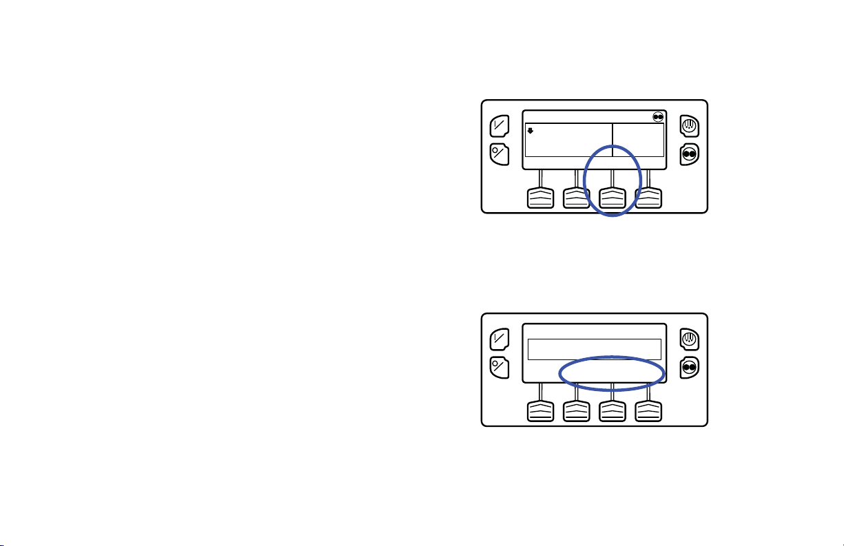
Operating Instructions
• Spare Digital Input 2 • Electric Ready Input
(SmartPower units only)
• Spare Digital Input 3 • Electric overload
(SmartPower units only)
• Spare Digital Input 4 • Hot Gas Bypass (ETV
units only)
• Spare Analog Input 1
• Spare Analog Input 2
Using The Sensors Key
The SENSORS Key allows the operator to view the unit
gauges. If the function of this key has been reassigned, the
SENSORS Menu is also available in the Maintenance Menu.
To access the SENSORS Menu, press the SENSORS Key:
ON
OFF
35
SET SENSORSGAUGES
POINT
°F
35
.8
MENU
Figure 65: Sensors Key
The first sensor display will appear. Press the NEXT and
BACK Keys to scroll through the sensors. Pressing the LOCK
Key will lock the current sensor on the display. (Figure 66)
CONTROL DISCHARGE AIR TEMPERATURE
ON
OFF
48.
3
BACK
°F
NEXTEXIT LOCK
Figure 66: Next, Back, Lock Keys
62

Operating Instructions
The sensors available are shown below.
To return to the Standard Display press the EXIT Key.
Sensors Available
Control Return Air Temperature: Displays the
temperature of the control return air sensor.
Display Return Air Temperature: Displays the
temperature of the display return air sensor.
Control Discharge Air Temperature: Displays the
temperature of the control discharge air sensor.
Display Discharge Air Temperature: Displays the
temperature of the display discharge air sensor.
Temperature Differential: Displays the calculated
difference between the control return air sensor and the control
discharge air sensor
Evaporator Coil Temperature: Displays the temperature
of the evaporator coil sensor.
Ambient Air Temperature: Displays the temperature of the
ambient air sensor.
* Spare 1 Temperature: Displays the temperature of the
spare 1 temperature sensor.
* Log Sensor 1: Displays the temperature of the
CargoWatch Data Logger temperature sensor 1.
* Log Sensor 2: Displays the temperature of the
CargoWatch Data Logger temperature sensor 2.
* Log Sensor 3: Displays the temperature of the
CargoWatch Data Logger temperature sensor 3.
* Log Sensor 4: Displays the temperature of the
CargoWatch Data Logger temperature sensor 4.
* Log Sensor 5: Displays the temperature of the
CargoWatch Data Logger temperature sensor 5.
* Log Sensor 6: Displays the temperature of the
CargoWatch Data Logger temperature sensor 6.
Board Temperature Sensor: Displays the internal
temperature of the HMI Control Panel pc board.
* If sensors have been added.
63
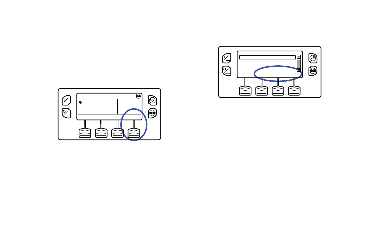
Operating Instructions
Using the Main Menu
The Main Menu contains several additional submenus that
allow the operator to view information and modify unit
operation. To access the Main Menu press the MENU Key
(Figure 67).
ON
OFF
35
SET SENSORSGAUGES
POINT
Figure 67: Menu Key
The first Main Menu choice will appear. Press and hold the UP
and DOWN Keys to scroll through the menu choices. When
the desired selection is shown on the display, press the
SELECT Key to access it. The Pretrip submenu is displayed
(Figure 68).
To return to the Standard Display press the EXIT Key.
°F
35
.8
MENU
PRETRIP
ON
LANGUAGE
ALARMS
GAUGES
OFF
MAIN MENU
DOWNEXIT SELECT UP
Figure 68: Pretrip Submenu
Main Menu Choices
Each of these Main Menu choices will be explained in
following pages of this chapter:
Pretrip: A Pretrip Test verifies unit operation.
Flash Drive: If a properly configured USB Flash Drive is
currently connected to the USB Port on the unit Control Panel,
the Flash Drive Menu will appear as a Main Menu selection.
Languages (If Enabled): If more th an one language is
enabled from the Guarded Access > Language Menu, this
menu item will appear.
64

Operating Instructions
Alarms: The Alarm Menu allows the operator to view any
active alarms, and allows most alarms to be cleared.
Gauges: The Gauges Menu allows the operator to view the
unit gauges and I/O conditions
Sensors: The Sensors Menu allows the operator to view the
unit and CargoWatch Data Logger temperature sensors.
Data Logger (CargoWatch): The CargoW atch Data Logger
is physically located in the HMI Control Panel. It can support
up to 6 optional temperature sensors
Hourmeters: The Hourmeters Menu allows the operator to
view the unit hourmeters that have the view feature enabled in
the Guarded Access menu.
Mode: The Mode Menu allows the operator to change the unit
operating modes that have been enabled in Guarded Access.
Keypad Lockout: If enabled in Guarded Access > Main
Menu Configuration, the keypad can be locked to prevent
unauthorized use.
Start Sleep Mode: If this feature enabled in Guarded Access
> Main Menu Configuration, the operator can select and set
Sleep Mode from the Mode Menu.
SmartPower™ Electric Standby Option: The
Diesel/Electric Standby selection from the Main Menu allows
the operator to manually select diesel or electric mode
operation on units equipped with the electric standby
SmartPower option.
Adjust Brightness: The brightness of the HMI Control
Panel display can be adjusted to allow for changing ambient
light conditions.
Time: The Time and Date held by the HMI Control Panel can
be checked. Time and Date cannot be changed from the Main
Menu.
Clear All ECU Faults: Pressing this key will clear all
existing Engine Control Unit (ECU) Fault Codes.
Pretrip
Pretrip Test verifies unit operation. This display allows a
Pretrip Test to be selected and initiated by the operator. If the
Pretrip Test is entered with the unit shut down a Full Pretrip
Test with device amp checks will be performed. If the Pretrip
Test is entered with the unit running in either diesel or electric
65

Operating Instructions
mode a Running Pretrip Test is performed. Test results are
reported as PASS, CHECK or FAIL when the Pretrip Test is
completed.
Pretrip Test Conditions
• Current unit settings are saved and restored at the end of
the Pretrip Test or if the unit is turned off and back on.
• Pretrip Test can be run in either Diesel or Electric Mode.
• The unit will auto switch from Diesel Mode to Electric
Mode or from Electric Mode to Diesel Mode during a
Pretrip Test if these features are enabled and the auto
switch conditions occur.
Conditions where Pretrip Tests are not allowed
• If any shutdown alarms are present. Pretrip tests are
allowed with some Check and Log alarms.
• If the unit is in Sleep Mode.
• If the unit is in Service Test Mode, Output Test Mode or
Evacuation Mode.
Pretrip Test Sequence
Pretrip tests proceed in the order shown below. A Full Pretrip
Test includes all tests. A Running Pretrip Test is started with
the engine or motor running and does not include the Amp
Checks or Engine Start Check.
Amp Checks - Each electrical control component is energized
and the current drawn is confirmed as within specification.
Engine Start - The Engine will start automatically.
Defrost - If the coil temperature is below 45 F (7 C), a defrost
cycle is initiated.
RPM Check - The engine RPM in high and low speed is
checked during the Cool Check.
Cool Check - The ability of the unit to cool in low speed is
checked.
Heat Check - The ability of the unit to heat in low speed is
checked.
Report Test Results - The test results are reported as PASS,
CHECK or FAIL when the Pretrip Test is completed. If test
results are CHECK or F AIL alarm codes will exist to direct the
technician to the source of the problem.
66

Operating Instructions
Pretrip Test Considerations
When performing a Pretrip Test, the following issues should be
considered.
• If running a Pretrip Test on a trailer loaded with dry cargo,
insure that proper airflow can occur around the load. If the
load restricts airflow, false test results may occur. Also,
Precedent units have high refrigeration capacity which
results in rapid temperature changes. Sensitive dry cargo
may be damaged as a result.
• If running a Pretrip Test on a trailer that has just been
washed down, the extremely high humidity inside the
trailer may result in false test results.
• If running a Pretrip Test on a trailer loaded with sensitive
cargo, monitor the load temperature during the test as
normal temperature control is suspended during pre-trip
operation.
• Always perform Pretrip Tests with the trailer cargo doors
closed to prevent false test failures.
Performing a Pretrip Test
If a Pretrip Test is initiated with the engine shut down a Full
Pretrip Test will be performed. If a Pretrip Test is initiated with
the engine or motor running a Running Pretrip Test is
performed.
• Before initiating a Pretrip Test, clear all alarm codes.
• To stop a Pretrip Test at any time turn the unit off.
Pretrip Tests are initiated using the Pretrip Menu. From the
Standard Display, press the MENU Key (Figure 69).
ON
OFF
35
SET SENSORSGAUGES
POINT
Figure 69: Menu Key
°F
35
.8
MENU
67

Operating Instructions
The Main Menu will appear. Press the UP or DOWN Key as
required to choose the Pretrip Menu. When the Pretrip Menu is
shown press the SELECT Key to start a Pretrip Test (Figure
70).
PRETRIP
ON
LANGUAGE
ALARMS
GAUGES
OFF
MAIN MENU
DOWNEXIT SELECT UP
Figure 70: Select Key
The display will briefly show PROGRAMMING PRETRIP
MODE (Figure 71). If the unit is not running a Full Pretrip Test
will be initiated. If the unit is running in either diesel or electric
mode a Running Pretrip Test will be performed.
PROGRAMMING PRETRIP MODE
ON
OFF
Figure 71: Programming Trip Mode
If all alarms were not cleared a prompt appears (Figure 72).
Exit the Pretrip Test, clear all alarms and repeat the Pretrip
Test.
ON
NO PRETRIP -- ALARM ACTIVE
OFF
EXIT
Figure 72: Alarms Not Cleared
68

Operating Instructions
If all alarms were cleared, the Pretrip Test display appears
(Figure 73).
NON-RUNNING PRETRIP
ON
OFF
HOUR
METERS
TEST 1 OF 26
SENSOR CHECK
SENSORS GAUGES
Figure 73: Pretrip Test
• The top line of the display indicates the unit is performing
the non-running portion of the Pretrip Test.
• The second line measures test progress. The number of
tests completed of the total number of tests to be
performed is shown. In the example above the unit is
performing Te st 1 of 26, Sensor Check.
• The soft keys may be used during the Pretrip T est to select
the Hourmeter, Gauge or Sensor menus.
• To stop a Pretrip Test at any time turn the unit off. This
will generate Alarm Code 28 Pretrip Abort. Other alarm
codes may also be generated. This is normal when the
Pretrip Test is halted before completion.
When the non-running tests are complete the unit will start
automatically and continue with the Running Pretrip Test. In
the example shown in Figure 74 the unit is in the Running
Pretrip and is performing Test 21 of 26, Cool Test.
ON
OFF
HOUR
METERS
RUNNING PRETRIP
TEST 21 OF 26
COOL TEST
SENSORS GAUGES
Figure 74: Cool Test
When all tests are complete, the results are reported as PASS,
CHECK or FAIL (Figure 75). If the results are CHECK or
F AIL, the accompanying alarm codes will direct the technician
to the cause of the problem.
69

Operating Instructions
ON
OFF
EXIT
PRETRIP
PASS
Figure 75: Pretrip Pass
If the Pretrip Test results are CHECK or FAIL the problem
should be diagnosed and corrected by a Thermo King service
technician before the unit is released for service.
To return to the Main Menu press the EXIT Key. To return to
the Standard display press the EXIT Key again.
See Figure 76 for an overview of the Performing a Pretrip
Test procedure.
70

Operating Instructions
MENU
35
°F
35
SET SENSORSGAUGES
POINT
.8
ON
OFF
Yes
PROGRAMMING PRETRIP MODE
ON
OFF
Alarms Cleared?
MAIN MENU
PRETRIP
ON
LANGUAGE
ALARMS
GAUGES
OFF
DOWNEXIT SELECT UP
ON
OFF
NO PRETRIP -- ALARM ACTIVE
EXIT
No
Exit Pretrip Test, clear alarms,
restart Pretrip T est.
NON-RUNNING PRETRIP
HOUR
METERS
TEST 1 OF 26
SENSOR CHECK
SENSORS GAUGES
ON
OFF
ON
OFF
ON
OFF
HOUR
METERS
EXIT
RUNNING PRETRIP
TEST 21 OF 26
COOL TEST
SENSORS GAUGES
PRETRIP
PASS
Figure 76: Performing a Pretrip Test
71
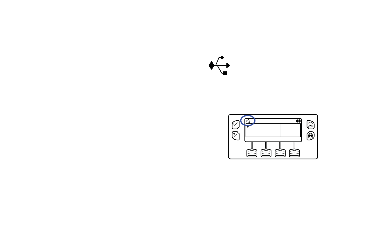
Operating Instructions
Flash Drive
If a properly configured USB Flash Drive is currently
connected to the USB Port on the unit Control Panel, the Flash
Drive Menu will appear as a Main Menu selection. If a
properly configured USB Flash Drive is connected to the USB
Flash Drive connector, this feature allows the operator to select
the desired Flash Drive function. If enabled when the Flash
Drive was configured, the following functions may be
available:
Download
• Download the ServiceWatch Data Logger
• Download the CargoWatch Data Logger
Flashload
• Flash load Base Controller Software
• Flash load HMI Control Panel Software
OptiSet Plus
•SEND
• Send OptiSet Plus files
RETRIEVE
• Retrieve OptiSet Plus files
If a USB Flash Drive is not connected to the unit, this feature
will not appear in the Main Menu.
Flash Drive Icon
•“The USB Icon (Figure 77) wil l appear in the
upper left cor ner of the disp lay as sh own b elow
when a USB Flash Drive is inserted into the
Flash Drive Only USB Port on the Unit Control
Panel.
•“The USB Icon will also appear if a computer
is connected to the PC Only USB Port on the
Unit Control Panel or inside the control box.
ON
OFF
35
SET SENSORSGAUGES
POINT
°F
35
.8
MENU
Figure 77: Flash Drive Icon
Selecting the Flash Drive Menu from the
Main Menu (If Already Connected)
To select the Flash Drive Menu, press the MENU Key (Figure
78). The Main Menu will appear.
72
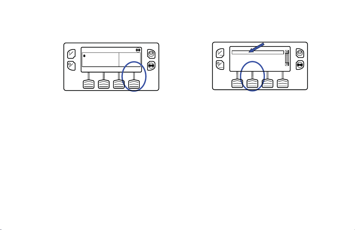
Operating Instructions
ON
OFF
35
SET SENSORSGAUGES
POINT
°F
35
.8
MENU
Figure 78: Menu Key
If a properly configured USB Flash Drive is connected to the
Flash Drive Only USB Port on the Control Panel, the Flash
Drive Menu will appear as a main Menu selection. Press the
UP or DOWN Key as required to choose the Flash Drive
Menu. When the Flash Drive Menu is shown press the
SELECT Key to select the Flash Drive menu. (Figure 79).
FLASH DRIVE
ON
PRETRIP
LANGUAGES
ALARMS
OFF
MAIN MENU
DOWNEXIT SELECT UP
Figure 79: Flash Drive Menu
Flash Drive (If Connected While the Unit is Turned
On)
If a properly configured USB Flash Drive is connected to the
USB Port on the unit Control Panel while the unit is turned on,
a Flash Drive indication will appear for several seconds. Then
the Flash Drive Menu will be shown (Figure 80).
73

Operating Instructions
ON
OFF
FLASH DRIVE DETECTED
EXIT DOWN FLASH OPTISET
LOAD LOAD PLUS
Figure 80: Flash Drive
Removing the Flash Drive
If the Flash Drive is disconnected, the display shown in Figure
81 will appear for 30 seconds and the display will return to the
Standard Display. To return to the Standard Display
immediately press the EXIT Soft Key.
ON
OFF
FLASH DRIVE REMOVED
EXIT HELP
Figure 81: Flash Drive Removed
If the HELP Sof t Key is pres sed the d isplay shown i n Figure 82
will appear.
ON
OFF
FLASH DRIVE REMOVED
PLEASE CHECK THE FLASH DRIVE FOR
PROPER INSERTION – REMOVE AND
REINSERT
EXIT
Figure 82: Help Soft Key Pressed
74

Operating Instructions
Languages (If Enabled)
If more than one language is enabled from the Guarded Access
> Language Menu, this menu item will appear. If only one
language is enabled, this menu will not appear. The Language
Menu allows the operator to select a language from the enabled
languages. All subsequent displays are shown in the selected
language. English is the default language. See the Guarded
Access Language Setup Menu in the Diagnostic Manual for
technical details.
If Languages are not enabled from the Guarded Access Menu,
this feature will not appear in the Main Menu.
IMPORTANT: Exercise care when changing languages, as
once changed all HMI Control Panel displays will be in the
new language.
Available Languages
The following languages are available:
• English • French • Spanish
Selecting an Alternate Language
To select an alternate language, press the MENU Key (Figure
83).
ON
OFF
35
SET SENSORSGAUGES
POINT
°F
35
.8
MENU
Figure 83: Menu Key
The Main Menu will appear. If more than one language is
enabled, the Language Menu will appear as a main Menu
selection (Figure 84). Press the UP or DOWN Key as required
to choose the Language Menu. When the Language Menu is
shown press the SELECT Key to select the Language menu.
75

Operating Instructions
PRETRIP
ON
LANGUAGE
ALARMS
GAUGES
OFF
MAIN MENU
DOWNEXIT SELECT UP
Figure 84: Main Menu
The Language menu will appear as shown in Figure 85. Press
the + or - Keys to select the desired language. Only languages
enabled from the Guarded Access Menu are available. When
the desired language is shown (example is Español [Spanish])
press the YES Key to confirm the choice.
Figure 85: Language Menu
The display will briefly show PROGRAMMING
LANGUAGE - PLEASE WAIT in the new language. The
display will then return to the Language Menu, but will show
the new language. Español (Spanish) is shown in Figure 86.
Figure 86: New Language (Example: Español)
76

Repeat the process to select a different language. To select a
different Main Menu item press the NEXT (SIGUIENTE) Key.
To return to the Standard Display press the EXIT (SALIDA)
Key.
All displays will now be in the new language. Español
(Spanish) is shown in Figure 87.
Figure 87: New Language (Example: Español)
To return to the Main Menu press the EXIT Key. To retu rn to
the Standard display press the EXIT Key again.
See Figure 88 for an overview of the Languages selection
procedure.
Operating Instructions
77

Operating Instructions
MENU
35
°F
35
SET SENSORSGAUGES
POINT
.8
ON
OFF
ON
OFF
PRETRIP
LANGUAGE
ALARMS
GAUGES
MAIN MENU
DOWNEXIT SELECT UP
ON
USE +/- TO CHANGE OK?
OFF
ON
OFF
BEENDEN WEITERAUSWHAL
NEW LANGUAGE WILL BE
DEUTSCH
-
+
HAUPTMENU
SPRACHE
YES NO
ON
OFF
SET SENSOREMESSGE
POINT
35
RAT N
°F
35
.8
MENU
Figure 88: Languages (If Enabled)
78

Language Menu Quick Access
Should it be necessary at any time to change to English or any
other installed language, return to the Standard Display and
then press and hold the first and last soft keys for 5 seconds as
shown below. The Standard Display shown in Figure 89 is
Español (Spanish).
Figure 89: Standard Display in Español
After 5 seconds the Language Menu will appear in the current
language as shown below. Press the + or - Keys to select the
desired langua ge. When the desired language i s shown press
the SI (YES) Key to confirm the choice (Figure 90).
Operating Instructions
Figure 90: Select Desired Language
NOTE: All languages in the installed software can be
selected using this method.
Alarms
The Alarm Menu allows the operator to view any active
alarms, and allows most alarms to be cleared.
Log Alarms
If only Log Alarms exist the display shown in Figure 91 will
appear and the optional remote alarm light will light for 30
seconds when the unit is turned on.
79

Operating Instructions
ON
OFF
LOG ALARMS ACTIVE
GO TO MENU TO VIEW
EXIT
Shutdown Alarms
If a Shutdown Alarm occurs while the unit is running it will be
indicated by all of the following (Figure 93):
• The Alarm Icon will appear.
• The display, backlight and optional remote alarm light will
flash on and off.
Figure 91: Log Alarms Exist
• The display will switch from normal video to reverse
video and back to norm al video. (Lig ht are as bec ome dark
and dark areas become light.)
Check Alarms
If a Check Alarm condition occurs while the unit is running the
alarm icon will appear in the display as shown in Figure 92.
ON
OFF
35
SET SENSORSGAUGES
POINT
35
MENU
Figure 92: Alarm Icon
ON
OFF
35
SET SENSORSGAUGES
POINT
35
MENU
Figure 93: Reverse/Normal Video
80

Operating Instructions
Pretrip Alarms
If an alarm occurs during a Pretrip Test the alarm code will be
displayed as Pretrip Alarm XX, wher e XX is the alar m code .
Alarm Codes When Switching Between Diesel and
Electric
If a shutdown alarm occurs that affects only diesel mode
operation and the unit is switched to electric, the diesel mode
shutdown alarm becomes an electric mode log alarm. This
allows the unit to run in electric mode without clearing the
shutdown alarm that is preventing diesel mode operation. If the
unit is switched back to diesel mode, the alarm again become a
diesel mode shutdown alarm and prevents unit operation.
In the same manner, if a shutdown alarm occurs that affects
only electric mode operation and the unit is switched to diesel,
the electric mode shutdown alarm becomes a diesel mode log
alarm to allow diesel mode operation. If the unit is switched
back to electric mode, the alarm reverts to an electric mode
shutdown alarm and prevents unit operation. If the unit is
configured for electric to diesel Auto-Switch, it automatically
starts and runs in diesel mode if an electric shutdown occurs.
Clearing Alarm Codes
Most alarm codes can be cleared conventionally from the
Alarm Menu using the CLEAR Key.
The following contr ol and di spl ay sens or ala rm code s can on ly
be cleared from the Maintenance Menu or Guarded Access
Menu:
• Alarm Code 03 Check Cont ro l Retu rn Air Sen so r
• Alarm Code 04 Check Cont ro l Discha rge Air Sensor
• Alarm Code 203 Check Display Return Air Sensor
• Alarm Code 204 Check Display Discharge Air Sensor
The following alarm codes clear automatically:
• Alarm Code 64 Pretrip Reminder - Clears when a Pretrip
Test is performed.
• Alarm Code 84 Restart Null - Clears when the unit is no
longer in a restart null due to a Prevent Alarm.
• Alarm Code 85 Forced Unit Operation - Clears when the
unit is no longer running in a forced mode due to a Prevent
Alarm.
• Alarm Code 91 Check Electric Ready Input - Clears
automatically when the unit starts running.
81

Operating Instructions
• Alarm Code 92 Sensor Grades Not Set - Clears when the
sensor grade is changed from 5H.
If the Limited Alarm Restarts feature is enabled the following
additional alarm codes may only be cleared from the Guarded
Access Menu. If this is the case, the CLEAR soft key will not
appear if the alarms are displayed from the Main Menu or the
Maintenance Menu.
• Alarm Code 10 High D ischarge Pressure
• Alarm Code 23 Cooling Cycle Fault
• Alarm Code 24 Heating Cycle Fault
• Alarm Code 32 Refrigeration Capacity Low
Displaying and Clearing Alarm Codes
Alarms are displayed and cleared using the Alarm Menu. From
the Standard Display, press the MENU Key (Figure 94).
ON
OFF
35
SET SENSORSGAUGES
POINT
35
MENU
The Main Menu will appear. Press the UP or DOWN Key as
required to choose the Alarms Menu (Figure 95). When the
Alarms Menu is shown press the SELECT Key to select the
Alarms menu.
PRETRIP
ON
LANGUAGE
ALARMS
GAUGES
OFF
MAIN MENU
DOWNEXIT SELECT UP
Figure 95: UP/Down, Select Keys
The number of alarms (if more than one) and a list of the
alarms with the most recent alarm first will be shown. In the
example below, there are two alarms. The most recent is Alarm
Code 5 Check Ambient Temp Sensor (Figure 96).
82
Figure 94: Menu Key

1 OF 2 ALARMS
CHECK AMBIENT TEMP SENSOR
5
ON
64
PRETRIP REMINDER
x
OFF
64
Figure 96: Alarms Menu
Operating Instructions
If the alarm situation has been resolved press the CLEAR Key
to clear the alarm (Figure 98).
DOWNEXIT CLEAR HELP
ON
OFF
1 OF 2 ALARMS
CHECK AMBIENT TEMP SENSOR
5
PRETRIP REMINDER
64
64
x
DOWNEXIT CLEAR HELP
If necessary to view all alarms, scroll down using the DOWN
Key (Figure 97).
Figure 98: Clear Key
The display will briefly show CLEARING ALARM 5 –
ON
OFF
PRETRIP REMINDER
64
64
x
DOWNEXIT CLEAR HELP
1 OF 2 ALARMS
CHECK AMBIENT TEMP SENSOR
5
PLEASE WAIT. Then the Alarm Menu will reappear
(Figure 99).
Note that Alarm Code 64 Pretrip Reminder cannot be cleared
using the CLEAR Key. This alarm will clear automatically
when a Pretrip Test is run.
Figure 97: Down Key
83

Operating Instructions
The Alarm Menu display will display the Shutdown Alarm
1 OF 1 ALARMS
PRETRIP REMINDER
64
ON
64
OFF
x
DOWNEXIT CLEAR HELP
Code. For additional information regarding the alarm shown
on the display, press the HELP Key (Figure 101).
1 OF 1 ALARMS
LOW ENGINE OIL LEVEL
66
ON
64
OFF
x
DOWNEXIT CLEAR HELP
Figure 99: Pretrip Reminder
If a serious condition occurs, the unit will be shut down to
prevent damage to the unit or the load. If this occurs, the Alarm
Icon will appear, the display and backlight will flash on and
Figure 101: Help Key
off. (Figure 100)
A help message will appear. Press the EXIT Key to return to
the Alarms Menu (Figure 102). Check the oil level and add oil
ON
OFF
35
SET SENSORSGAUGES
POINT
35
MENU
as required, clear the alarm and restart the engine.
84
Figure 100: Unit Shutdown

Operating Instructions
ON
OFF
LOW ENGINE OIL LEVEL
CHECK ENGINE OIL LEVEL. IF UNIT IS SHUT
DOWN REPAIR IMMEDIATELY. OTHERWISE
REPORT ALARM AT END OF DAY.
EXIT
Figure 102: Exit Key
To return to the Main Menu press the EXIT Key. To retu rn to
the Standard display press the EXIT Key again.
Important Alarm Notes
• If an alarm will not clear, it may still exist. If the alarm is
not corrected, it will not clear or may be immediately set
again.
• If an alarm cannot be cleared from the Main menu, the
Clear Key will not appear. These alarms must be cleared
from the Maintenance or Guarded Access Menus.
See Figure 103 for an overview of the Displaying and
Clearing Alarm Codes procedure.
85

Operating Instructions
CHECK ENGINE OIL LEVEL. IF UNIT IS SHUT
DOWN REPAIR IMMEDIATELY. OTHERWISE
REPORT ALARM AT END OF DAY.
LOW ENGINE OIL LEVEL
EXIT
86
LOG ALARMS ACTIVE
ON
GO TO MENU TO VIEW
OFF
EXIT
ON
35
OFF
SET SENSORSGAUGES
POINT
35
MENU
ON
35
OFF
SET SENSORSGAUGES
POINT
35
MENU
ON
35
OFF
SET SENSORSGAUGES
POINT
PRETRIP
ON
LANGUAGE
ALARMS
GAUGES
OFF
CHECK AMBIENT TEMP SENSOR
5
ON
64
PRETRIP REMINDER
x
64
OFF
MAIN MENU
1 OF 2 ALARMS
35
MENU
DOWNEXIT SELECT UP
DOWNEXIT CLEAR HELP
ON
OFF
ON
OFF
ON
OFF
1 OF 2 ALARMS
CHECK AMBIENT TEMP SENSOR
5
PRETRIP REMINDER
64
64
x
1 OF 2 ALARMS
CHECK AMBIENT TEMP SENSOR
5
PRETRIP REMINDER
64
64
x
1 OF 1 ALARMS
PRETRIP REMINDER
64
64
x
DOWNEXIT CLEAR HELP
DOWNEXIT CLEAR HELP
DOWNEXIT CLEAR HELP
ON
35
OFF
SET SENSORSGAUGES
POINT
LOW ENGINE OIL LEVEL
66
ON
64
x
OFF
ON
OFF
1 OF 1 ALARMS
35
MENU
DOWNEXIT CLEAR HELP
Figure 103: Displaying and Clearing Alarm Codes

Operating Instructions
Gauges
The Gauges Menu allows the operator to view the unit gauges
and I/O conditions. The unit gauges can always be viewed
from the Main Menu. This is necessary if the GAUGES Soft
Key on the Standard Display has been reassigned to a different
function.
Displaying Gauges
Gauges are displayed using the Gauges Menu. From th e
Standard Display, press the MENU Key (Figure 104).
ON
OFF
35
SET SENSORSGAUGES
POINT
Figure 104: Menu Key
°F
35
.8
MENU
The Main Menu will appear. Press the UP or DOWN Key as
required to choose the Gauges Menu. When the Gauges Menu
is selected, press the SELECT Key to choose the Gauges menu
(Figure 105).
PRETRIP
ON
LANGUAGE
ALARMS
GAUGES
OFF
MAIN MENU
DOWNEXIT SELECT UP
Figure 105: Up, Down, Select Keys
The first gauge display will appear. Press the NEXT and
BACK Keys to scroll through the gauges and I/O conditions.
Pressing the LOCK Key will lock the current gauge on the
display (Figure 106).
87
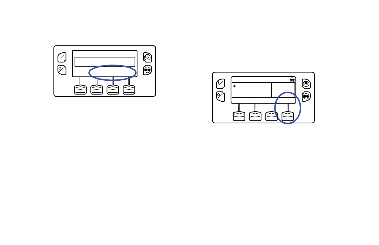
Operating Instructions
ON
OFF
BATTERY VOLTAGE
8
13.
v
NEXTEXIT LOCK BACK
Figure 106: Next, Back, Lock Keys
The gauges and I/O conditions available are described in this
section of the manual. Not all gauges or I/O conditions may
appear depending on unit configuration and soft ware revision.
To return to the Main Menu press the EXIT Key. To return to
the Standard display press the EXIT Key again.
Sensors
The Sensors Menu allows the operator to view the unit and
CargoWatch Data Logger temperature sensor s. The sensors c an
always be viewed from the Main Menu. This is necessary if the
SENSORS Soft Key on the Standard Display has been
reassigned to a different function.
Displaying Sensors
Sensors are displayed using the Sensors Menu. From the
Standard Display, press the MENU Key (Figure 107).
ON
OFF
35
SET SENSORSGAUGES
POINT
Figure 107: Menu Key
The Main Menu will appear. Press the UP or DOWN Key as
required to choose th e Sensors Menu. When the Sen sor s M enu
is selected, press the SELECT Key to choose the Sensors
menu.
The first sensors display will appear. Press the NEXT and
BACK Keys to scroll through the sensors. Pressing the LOCK
Key will lock the current gauge on the display (Figure 108).
°F
35
.8
MENU
88

Operating Instructions
CONTROL DISCHARGE AIR TEMPERATURE
ON
OFF
48.
3
BACK
°F
NEXTEXIT LOCK
Figure 108: Next, Back, Lock Keys
The sensors available are described in this section of the
manual.
To return to the Main Menu press the EXIT Key. To retu rn to
the Standard display press the EXIT Key again.
Data Logger (CargoWatch)
The CargoW atch Data Logger is physically located in the HMI
Control Panel. It can support up to 6 optional temperature
sensors.
When shipped from the factory, CargoWatch sensors 1 and 2
are turned on to be logged and CargoW atch sensors 3 through 6
are turned off. Also, digital input 1 is turned on to be logged
and digital inputs 2 through 4 are turned off. Sensors and
digital inputs can be turned on, off and configured using the
CargoWatch menu in Guarded Access or with Wintrac. The
CargoWatch Data Logger can also be configured using the
USB Flash Drive OptiSet Plus Feature.
A Start of Trip can be sent to the unit ServiceWatch and
CargoWatch Data Loggers. In addition, the CargoWatch Data
Logger contents can be printed with a hand-held printer.
The ServiceWatch and CargoWatch Data Logger are accessed
using the Data Logger Menu. From the Stan dard Display, press
the MENU Key (Figure 109).
ON
OFF
35
SET SENSORSGAUGES
POINT
°F
35
.8
MENU
Figure 109: Standard Screen, Menu Key
89
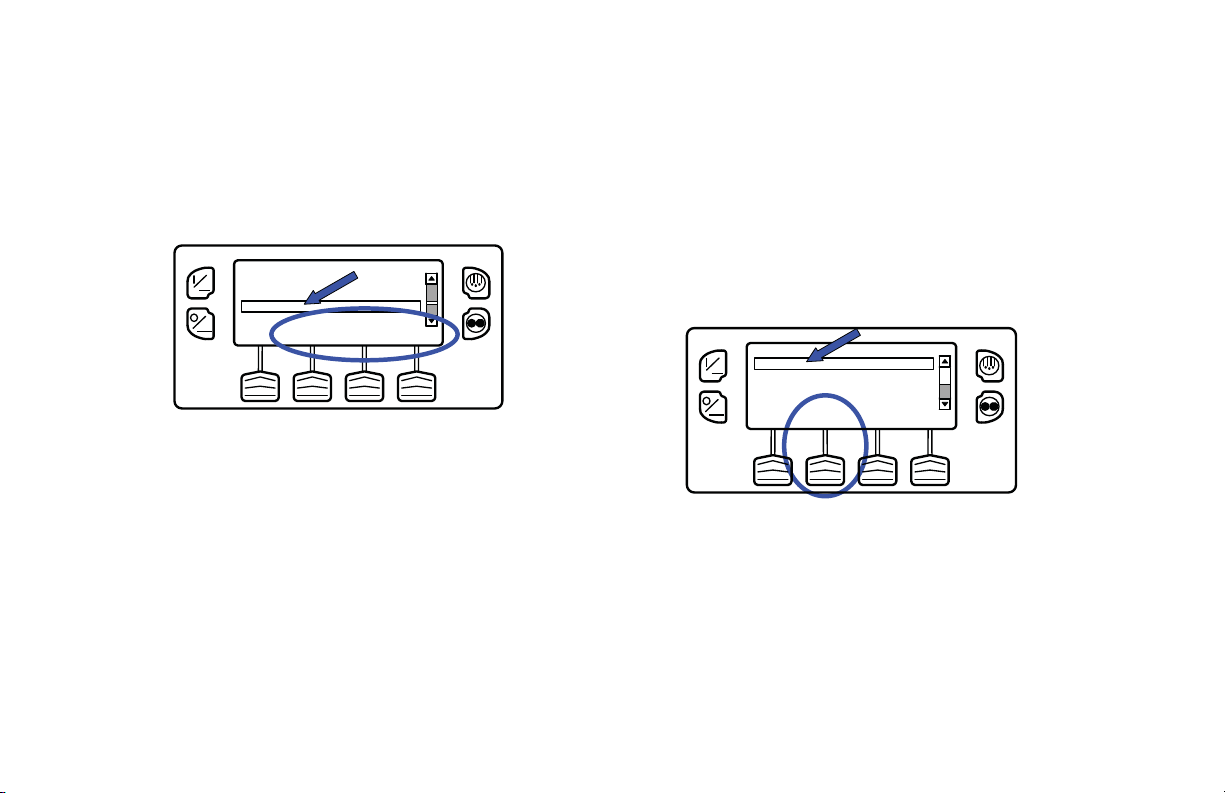
Operating Instructions
The Main Menu will appear. Press the UP or DOWN Key as
required to choose the Data Logger Menu. When the Data
Logger Menu is selected, press the SELECT Key to choose the
Data Logger menu (Figure 110).
GAUGES
ON
SENSORS
DATA LOGGER
HOURMETERS
OFF
MAIN MENU
DOWNEXIT SELECT UP
Figure 110: UP, Down, Select Keys
The Data Logger Menu will appear.
Sending Start of Trip Marker to CargoWatch
and ServiceWatch Data Loggers
To send a Start of Trip marker to the CargoWatch and
ServiceWatch Data Loggers press the SELECT Key. The
display will briefly show START OF TRIP COMPLETE to
confirm that a Start of Trip marker was set in the CargoWatch
Data Logger (Figure 111).
ON
OFF
Figure 111: Select Key, Start of Trip Complete
NOTE: The start of trip marker is sent to both the
CargoWatch and ServiceWatch data loggers.
START TRIP
PRINT/VIEW
DATA LOGGER
DOWNEXIT SELECT UP
90
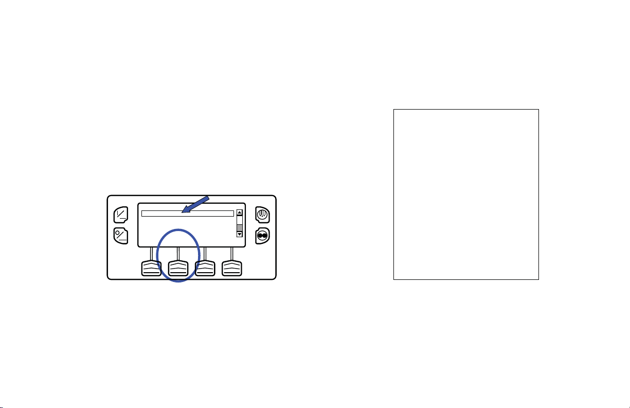
Printing CargoWatch Dat a Logger Reports
UNIT S ER I A L NUMBER :
CONT ROLL ER SERIAL NUMBE R:
CONT ROLL ER VERSION NU MBE R:
TRAILE R ID:
CONT ROLLE R TYPE :
TEMPER A TUR E UNI TS :
DATALOG GER VE RSION NUMBER:
START:
FINISH:
SENSORS:
SETPOI NT:
xxxxxxxxxx
A00021506190T3
xxxxxxxxxx
B007
SR2
6512
FAHRENHEIT
05/30/08 08:29:08
05/30/08 09:18:33
2
32.0
Sensor Min Ave Max Last
#1: 35 35
35 35
SENSOR #1: LOG SENSOR 1
SENSOR #2: LOG SENSOR 2
#2: - - - - - - - - - - - -
Press the DOWN Key to select the PRINT / VIEW feature and
press the SELECT Key to choose Print/View.
The Print Data Menu will appear . The first Print Data Menu
allows the operator to print a Delivery Ticket using a hand held
printer. Pressing the SELECT Key will print the ticket (Figure
112). The Delivery Ticket is a short ticket that shows delivery
specific details including the current temperature. A sample
Delivery Ticket is shown in Figure 113.
PRINT DATA
DELIVERY TICKET
ON
TRIP TICKET
Operating Instructions
OFF
Figure 112: Select Key, Print Delivery Ticket
DOWNEXIT SELECT UP
Figure 113: Sample Delivery Ticket
91
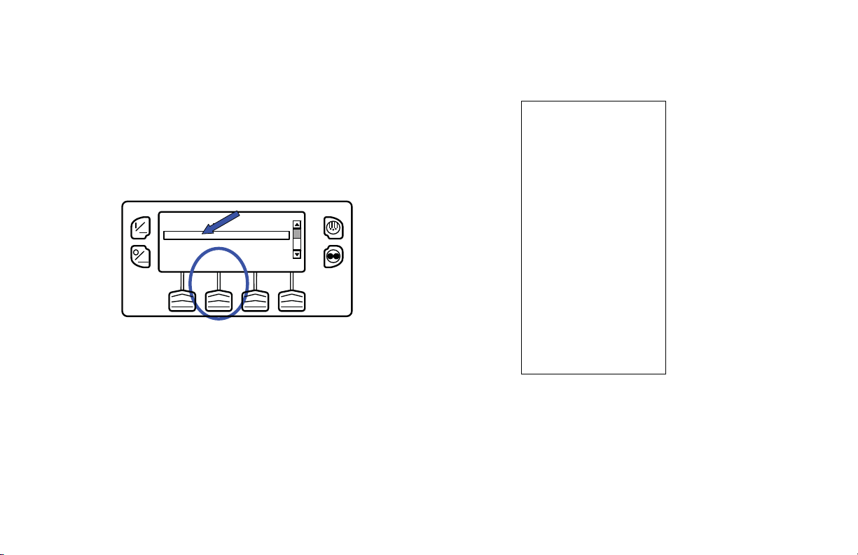
Operating Instructions
UNIT SER I AL NUMBER :
CONTROLL ER SERIAL NUMBER:
CONTROLL ER VERSION NUM B ER:
TRAILER ID:
CONTROLL ER TYP E :
TEMPERA TURE UN I TS:
DATALOGGER VERSION NU MBER:
START:
FINISH:
SENSORS:
SETPOINT:
xxxxxxxxxx
A00021506190T3
xxxxxxxxxx
B007
SR2
6512
FAHRENHEIT
05/30/08 09:50:08
05/30/08 13:07:33
1
32.0
SENSOR #1: LOG SEN SOR 1
SENSOR #2: LOG SEN SOR 2
30 - MAY - 2008
1305 35.0
1250 35.2
1235 35.1
1220 35.2
1205 35.1
1150 35.0
1135 35.0
30 - MAY - 2008
1120 35.0
1105 34.9
1050 35.0
1035 35.0
1020 35.0
1005 35.1
0950 35.1
Pressing the DOWN Key allows the operator to print a Trip
Ticket using a hand held printer. Press the SELECT Key to
print the ticket (Figure 114). The Trip Ticket is a long ticket
that shows details for the current trip including a temperature
history. The Trip Ticket is also called a Journey Ticket. A
sample Trip Ticket is shown in Figure 115.
92
Figure 114: Select Key, Print Trip Ticket
ON
OFF
DELIVERY TICKET
TRIP TICKET
PRINT DATA
DOWNEXIT SELECT UP
Figure 115: Sample Trip Ticket

Hourmeters
The Hourmeters Menu allows the operator to view the unit
hourmeters that have the view feature enabled in the Guarded
Access menu. If the view feature for a particular hourmeter is
not enabled then that hourmeter will continue to accumulate
time but cannot be viewed from the Main Menu. However, all
hourmeters can be viewed from the Maintenance Menu, even if
they are not enabled. The hourmeters shown below are
implemented.
ON
OFF
35
SET SENSORSGAUGES
POINT
Figure 116: Menu Key
Operating Instructions
°F
35
.8
MENU
Viewing Hourmeters
Only Hourmeters that have been enabled in Guarded Access
are shown from the Main Menu. The Hourmeters can be
viewed only.
Hourmeters are displayed using the Hourmeter Display. From
the Standard Display, press the MENU Key (Figure 116).
The Main Menu will appear. Press the UP or DOWN Key as
required to choose the Hourmeter Menu. When the Hourmeter
Menu is selected, press the SELECT Key to choose the
Hourmeter Menu (Figure 117).
SENSORS
ON
DATA LOGGER
HOURMETERS
MODE
OFF
MAIN MENU
DOWNEXIT SELECT UP
Figure 117: Select Key
93

Operating Instructions
Press the NEXT or PREVIOUS Key to scroll through the
hourmeters (Figure 118).
HOURMETERS
TOTAL UNIT RUN HOURS
ON
TOTAL ENGINE RUN HOURS
TOTAL ELECTRIC RUN HOURS
OFF
833
DOWNEXIT SELECT UP
Figure 118: Up/Down Keys
Hourmeter names and definitions are shown in the table on the
next page in the order they appear. Only hourmeters enabled in
the Guarded Access Menu will be shown. To return to the
Standard Display, press the EXIT Key.
When shipped from the factory, only these hourmeters are
enabled for viewing from the Main Menu.
• Total Unit Run Hours
• Total Engine Run Hours
• Total Electric Run Hours
To return to the Main Menu press the EXIT Key. To return to
the Standard display press the EXIT Key again.
Hourmeter Names and Definitions
Only configured hourmeters that have been enabled in the
Viewable Hourmeter Setup Menu will be shown:
Hourmeter
Name
Total Hours Total number of hours the unit has been
Total Run
Time Hours
Engine Hours Total number of hours the unit has run in
Electric Run
Hours
Total Run
Reminder 1
Total Run
Reminder 2
Definition
turned on (protection hours ).
Total number of hours the unit has run in
both diesel and electric mode.
diesel mode.
Total number of hours the unit has run in
electric mode.
User Programmabl e - The nu mb er of hou rs
before a Total Unit Run Time Maintenance
Reminder 1 occurs.
User Programmabl e - The nu mb er of hou rs
before a Total Unit Run Time Maintenance
Reminder 2 occurs.
94

Operating Instructions
Controller
Power On
Pretrip
Reminder
Engine
Reminder 1
Total hours the controller and HMI Control
Panel have been turned on.
User Programm able - number of hours
before a Pretrip Reminder occurs.
User Programmable - The number of
hours before an Engine Run Time
Maintenance Reminder 1 occurs.
Engine
Reminder 2
User Programmable - The number of
hours before an Engine Run Time
Maintenance Reminder 2 occurs.
Electric
Reminder 1
User Programmable - The number of
hours before an Electric Run Time
Maintenance Reminder 1 occurs.
Electric
Reminder 2
User Programmable - The number of
hours before an Electric Run Time
Maintenance Reminder 2 occurs.
IMPORTANT: If a programmable hourmeter is not enabled
or the view for that hourmeter is not turned on it will not
appear in the display sequence.
Mode
The Mode Menu allows the operator to change the unit
operating modes that have been enabled in Guarded Access.
Only Operating Modes tha t have bee n en abl e d fr om the
Guarded Access > Main Menu Configuration Menu will be
shown.
• Turns O ff Cycle Sentry Mode/Turns On Cycle Sentry
Mode (If Cycle Sentry is turned Off unit runs in
Continuous). Note that selecting Cycle Sentry Mode or
Continuous Mode can also be accomplished using the
Cycle Sentry Key to the right of the display.
• Allows temperature to be displayed in either Fahrenheit or
Celsius degrees (if enabled from the Guarded Access >
Main Menu Configuration Menu).
• Allows the opti onal Fresh A ir Exchan ge door to be open ed
or closed (if enabled from the Guarded Access >
Hardware Configuration Menu).
• Allows Keypad Lockout to be selected (if enabled from
the Guarded Access > Main Menu Configuration Menu).
• Start Sleep Mode (if enabled from the Guarded Access >
Main Menu Configuration Menu).
95

Operating Instructions
When shipped from the factory, only the Cycle
Sentry/Continuous Mode is enabled.
If OptiSet Plus is in use some modes may not be available.
To return to the Main Menu press the EXIT Key. To return to
the Standard display press the EXIT Key again.
Using the Change Mode Menu
Mode changes are made using the Mode Menu. From the
Standard Display, press the MENU Key (Figure 119).
ON
OFF
35
SET SENSORSGAUGES
POINT
°F
35
.8
MENU
Figure 119: Menu Key
The Main Menu will appear. Press the UP or DOWN Key as
required to choose the Mode Menu. When the Mode Menu is
selected, press the SELECT Key to choose the Mode Menu
(Figure 120).
ON
OFF
DATA LOGGER
HOURMETERS
MODE
ELECTRIC STANDBY
MAIN MENU
DOWNEXIT SELECT UP
Figure 120: Up, Down, Select Keys
The first enabled Change Mode Menu selection will appear. To
choose that function, press the SELECT Soft Key. To Scroll
through the enabled features in the Change Mode Menu, press
the UP and DOWN Soft Keys (Figure 121).
96

CHANGE MODE
TURN ON CYCLE SENTRY MODE
ON
FAHRENHEIT
KEYPAD LOCKOUT
START SLEEP MODE
OFF
DOWNEXIT SELECT UP
Figure 121: Select, Up, Down Keys
Operating Instructions
Turn Cycle Sentry On or Off
Cycle Sentry Mode can be turned On or Off if Cycle Sen t ry
Mode is allowed by OptiSet Plus. If Cycle Sentry is turned off
the unit runs in Continuous mode, unless Continuous Mode is
not allowed by OptiSet Plus. Either Cycle Sentry or
Continuous operation can be disabled via OptiSet Plus. From
the Main Menu > Change Mode menu choose Turn On/Off
Cycle Sentry Mode and press the SELECT Soft Key (Figure
122).
Possible mode selections are shown later in this section.
• Only those modes that have been enabled will appear.
Only the Cycle Sentry Menu is enabled on factory uni t s.
• Not all modes may be available, depending on OptiSet
Plus usage and the settings of other programmable
features.
• To return to the Standard Display press the EXIT Key.
• The modes shown on the follo win g pa ges ma y be
available.
CHANGE MODE
TURN ON CYCLE SENTRY MODE
ON
OFF
FAHRENHEIT
KEYPAD LOCKOUT
START SLEEP MODE
Figure 122: Select Key
DOWNEXIT SELECT UP
97
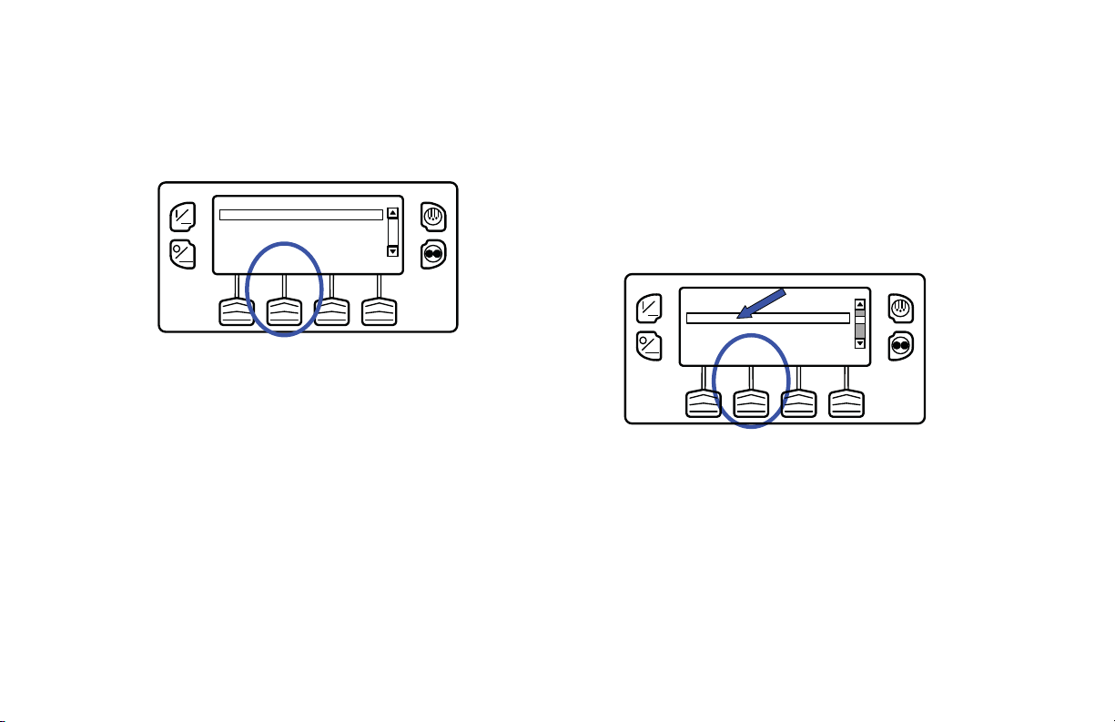
Operating Instructions
If the unit is running in Cycle Sentry Mode, press the SELECT
Soft Key (Figur e 1 23) to turn off Cycle Sentr y M ode as shown
below.
CHANGE MODE
TURN OFF CYCLE SENTRY
ON
OFF
EXIT SELECT
Figure 123: Select Key
Confirmation screens will appear briefly , the unit will switch to
Continuous Mode operation and the Cycle Sentry Icon will
disappear.
To turn Cycle Sentry back on press the SELECT Key again.
To leave this menu without changing the setting, press the
EXIT Soft Key. To return to the Standard Display press the
EXIT Soft Key again.
NOTE: Cycle Sentry Mode can also be turned on and off
using the Cycle Sentry Key on the HMI Control Panel unless
the Soft Key function has been reassigned.
Select Temperature Units
If this feature enabled in Guarded Access > Main Menu
Configuration, the operator can select temperature units to be
displayed as either degrees Fahrenheit or degrees Celsius.
From the Main Menu > Change Mode menu ch oose Fahren heit
or Celsius and press the SELECT Soft Key (Figure 124).
ON
OFF
Figure 124: Fahrenheit or Celsius, Select Key
Choose the desired Temperature Units using the UP and
DOWN Soft Keys and press the SELECT Soft Key to select
the choice (Figure 125).
CHANGE MODE
TURN ON CYCLE SENTRY MODE
FAHRENHEIT
KEYPAD LOCKOUT
START SLEEP MODE
DOWNEXIT SELECT UP
98
 Loading...