

Page 1

Operator’s Manual
T-1090 SPECTRUM
Multi-Temperature Unit with Premium HMI
September 2019
Revision A
TTKK 5566770044--11--OOPP--EENN
Page 2

Introduction
This manual is published for informational purposes only and the
information furnished herein should not be considered as all-inclusive or
meant to cover all contingencies. If more information is required, consult
your Thermo King Service Directory for the location and telephone number
of the local dealer.
TThheerrmmoo KKiinngg’’ss wwaarrrraannttyy sshhaallll nnoott aappppllyy ttoo aannyy eeqquuiippmmeenntt wwhhiicchh hhaass
bbeeeenn ““ssoo iinnssttaalllleedd,, mmaaiinnttaaiinneedd,, rreeppaaiirreedd oorr aalltteerreedd aass,, iinn tthhee
mmaannuuffaaccttuurreerr’’ss jjuuddggmmeenntt,, ttoo aaffffeecctt iittss iinntteeggrriittyy..””
MMaannuuffaaccttuurreerr sshhaallll hhaavvee nnoo lliiaabbiilliittyy ttoo aannyy ppeerrssoonn oorr eennttiittyy ffoorr aannyy
ppeerrssoonnaall iinnjjuurryy,, pprrooppeerrttyy ddaammaaggee oorr aannyy ootthheerr ddiirreecctt,, iinnddiirreecctt,, ssppeecciiaall,,
oorr ccoonnsseeqquueennttiiaall ddaammaaggeess wwhhaattssooeevveerr,, aarriissiinngg oouutt ooff tthhee uussee ooff tthhiiss
mmaannuuaall oorr aannyy iinnffoorrmmaattiioonn,, rreeccoommmmeennddaattiioonnss oorr ddeessccrriippttiioonnss
ccoonnttaaiinneedd hheerreeiinn.. TThhee pprroocceedduurreess ddeessccrriibbeedd hheerreeiinn sshhoouulldd oonnllyy bbee
uunnddeerrttaakkeenn bbyy ssuuiittaabbllyy qquuaalliiffiieedd ppeerrssoonnnneell.. FFaaiilluurree ttoo iimmpplleemmeenntt tthheessee
pprroocceedduurreess ccoorrrreeccttllyy mmaayy ccaauussee ddaammaaggee ttoo tthhee TThheerrmmoo KKiinngg uunniitt oorr
ootthheerr pprrooppeerrttyy oorr ppeerrssoonnaall iinnjjuurryy..
There is nothing complicated about operating and maintaining your Thermo
King unit, but a few minutes studying this manual will be time well spent.
Performing pre-trip checks and enroute inspections on a regular basis will
minimize operating problems. A regular maintenance program will also help
to keep your unit in top operating condition. If factory recommended
procedures are followed, you will find that you have purchased the most
efficient and dependable temperature control system available.
All service requirements, major and minor, should be handled by a Thermo
King dealer for four very important reasons:
• They are equipped with the factory recommended tools to perform all
service functions
• They have factory trained and certified technicians
• They have genuine Thermo King replacement parts
• The warranty on your new unit is valid only when the repair and
replacement of component parts is performed by an authorized Thermo
King dealer
2
TK 56704-1-OP-EN
Page 3
IInnttrroodduuccttiioonn
Customer Satisfaction Survey
Let your voice be heard!
Your feedback will help improve our manuals. The survey is accessible
through any internet-connected device with a web browser.
Scan the Quick Response (QR) code or click or type the web address http://
irco.az1.qualtrics.com/SE/?SID=SV_2octfSHoUJxsk6x to complete the
survey.
TK 56704-1-OP-EN
3
Page 4

Table of Contents
SSaaffeettyy PPrreeccaauuttiioonnss .............................. .. .. .. .. .. .. .. .. .. .. .. .. .. .. .. ........................ 88
Danger, Warning, Caution, and Notice . . . . . . . . . . . . . . . . . . . . . . . . 8
General Practices . . . . . . . . . . . . . . . . . . . . . . . . . . . . . . . . . . . . . . . . . . . 8
Automatic Start/Stop Operation. . . . . . . . . . . . . . . . . . . . . . . . . . . . . . 9
Electrical Hazard . . . . . . . . . . . . . . . . . . . . . . . . . . . . . . . . . . . . . . . . . . . 10
Low Voltage . . . . . . . . . . . . . . . . . . . . . . . . . . . . . . . . . . . . . . . . . . . 11
Refrigeration System Hazards . . . . . . . . . . . . . . . . . . . . . . . . . . . . . . 11
Refrigerant Oil Hazards . . . . . . . . . . . . . . . . . . . . . . . . . . . . . . . . . 12
First Aid . . . . . . . . . . . . . . . . . . . . . . . . . . . . . . . . . . . . . . . . . . . . . . . 12
Welding Precautions . . . . . . . . . . . . . . . . . . . . . . . . . . . . . . . . . . . . . . . 14
Safety Nameplates. . . . . . . . . . . . . . . . . . . . . . . . . . . . . . . . . . . . . . . . . 15
UUnniitt DDeessccrriippttiioonn................ .. .. .. .. .. .. .. .. .. .. .. .. .. .. ............................................1166
General Description. . . . . . . . . . . . . . . . . . . . . . . . . . . . . . . . . . . . . . . . 16
Design Features . . . . . . . . . . . . . . . . . . . . . . . . . . . . . . . . . . . . . . . . . . . 17
Unit Options . . . . . . . . . . . . . . . . . . . . . . . . . . . . . . . . . . . . . . . . . . . . . . 18
Engine . . . . . . . . . . . . . . . . . . . . . . . . . . . . . . . . . . . . . . . . . . . . . . . . . . . . 19
ELC (Extended Life Coolant) . . . . . . . . . . . . . . . . . . . . . . . . . . . . . . . . 19
Clutch . . . . . . . . . . . . . . . . . . . . . . . . . . . . . . . . . . . . . . . . . . . . . . . . . . . . 19
Reciprocating Compressor . . . . . . . . . . . . . . . . . . . . . . . . . . . . . . . . . 20
HMI Controller. . . . . . . . . . . . . . . . . . . . . . . . . . . . . . . . . . . . . . . . . . . . . 20
CYCLE-SENTRY™ Start/Stop System . . . . . . . . . . . . . . . . . . . . . . . . 20
Defrost . . . . . . . . . . . . . . . . . . . . . . . . . . . . . . . . . . . . . . . . . . . . . . . . . . . 20
TracKing™ . . . . . . . . . . . . . . . . . . . . . . . . . . . . . . . . . . . . . . . . . . . . . . . . 21
SmartPower Electric Standby (Model 50 Units Only) . . . . . . . . . . 21
SmartPower Standard Features . . . . . . . . . . . . . . . . . . . . . . . . . 21
SmartPower Optional Features . . . . . . . . . . . . . . . . . . . . . . . . . . 22
4
TK 56704-1-OP-EN
Page 5

TTaabbllee ooff CCoonntteennttss
Unit Protection Devices . . . . . . . . . . . . . . . . . . . . . . . . . . . . . . . . . . . . 22
Engine Compartment Components. . . . . . . . . . . . . . . . . . . . . . . . . . 22
Unit Components . . . . . . . . . . . . . . . . . . . . . . . . . . . . . . . . . . . . . . . . . . 23
OOppeerraattiinngg IInnssttrruuccttiioonnss ffoorr PPrreemmiiuumm HHMMII CCoonnttrrooll
PPaanneell........................................ .. .. .. .. .. .. .. .. .. .. .. .. .. .. ............................................2266
Truck Premium Display HMI Control Panel . . . . . . . . . . . . . . . . . . . 26
Display . . . . . . . . . . . . . . . . . . . . . . . . . . . . . . . . . . . . . . . . . . . . . . . . 26
Hard Keys . . . . . . . . . . . . . . . . . . . . . . . . . . . . . . . . . . . . . . . . . . . . . 27
Soft Keys . . . . . . . . . . . . . . . . . . . . . . . . . . . . . . . . . . . . . . . . . . . . . . 28
Turning the Unit On and Off. . . . . . . . . . . . . . . . . . . . . . . . . . . . . 29
If More Than One Language is Enabled . . . . . . . . . . . . . . . . . . . . 30
The Standard Display. . . . . . . . . . . . . . . . . . . . . . . . . . . . . . . . . . . 33
Changing the Setpoint . . . . . . . . . . . . . . . . . . . . . . . . . . . . . . . . . . 34
Starting the Diesel Engine . . . . . . . . . . . . . . . . . . . . . . . . . . . . . . 36
Starting the Electric Motor . . . . . . . . . . . . . . . . . . . . . . . . . . . . . . 37
Switching from Diesel to Electric . . . . . . . . . . . . . . . . . . . . . . . . 38
Switching from Electric to Diesel . . . . . . . . . . . . . . . . . . . . . . . . 39
Initiating a Manual Defrost Cycle . . . . . . . . . . . . . . . . . . . . . . . . 41
Terminating a Defrost Cycle . . . . . . . . . . . . . . . . . . . . . . . . . . . . . 42
Selecting High Speed Lockout Mode (If Enabled) . . . . . . . . . 42
Using the Gauges Key . . . . . . . . . . . . . . . . . . . . . . . . . . . . . . . . . . 44
Gauges Available . . . . . . . . . . . . . . . . . . . . . . . . . . . . . . . . . . . . . . 45
Using the Sensors Key . . . . . . . . . . . . . . . . . . . . . . . . . . . . . . . . . 46
Sensors Available . . . . . . . . . . . . . . . . . . . . . . . . . . . . . . . . . . . . . 47
Using The Main Menu . . . . . . . . . . . . . . . . . . . . . . . . . . . . . . . . . . 48
Main Menu Choices . . . . . . . . . . . . . . . . . . . . . . . . . . . . . . . . . . . . 48
Languages Menu . . . . . . . . . . . . . . . . . . . . . . . . . . . . . . . . . . . . . . 50
Alarms . . . . . . . . . . . . . . . . . . . . . . . . . . . . . . . . . . . . . . . . . . . . . . . . 53
Log Alarms . . . . . . . . . . . . . . . . . . . . . . . . . . . . . . . . . . . . . . . . . . . 53
Check Alarms . . . . . . . . . . . . . . . . . . . . . . . . . . . . . . . . . . . . . . . . . 54
Shutdown Alarms . . . . . . . . . . . . . . . . . . . . . . . . . . . . . . . . . . . . . 54
Prevent Alarms. . . . . . . . . . . . . . . . . . . . . . . . . . . . . . . . . . . . . . . . 54
TK 56704-1-OP-EN
5
Page 6

TTaabbllee ooff CCoonntteennttss
Pretrip Alarm Codes. . . . . . . . . . . . . . . . . . . . . . . . . . . . . . . . . . . . 55
Alarm Codes When Switching Between Diesel and
Electric . . . . . . . . . . . . . . . . . . . . . . . . . . . . . . . . . . . . . . . . . . . . . . 55
Alarm Code Notification . . . . . . . . . . . . . . . . . . . . . . . . . . . . . . . . 56
Clearing Alarm Codes . . . . . . . . . . . . . . . . . . . . . . . . . . . . . . . . . . 56
Displaying and Clearing Alarm Codes . . . . . . . . . . . . . . . . . . . . . 57
Table of Alarm Codes . . . . . . . . . . . . . . . . . . . . . . . . . . . . . . . . . . 60
Datalogger Menu . . . . . . . . . . . . . . . . . . . . . . . . . . . . . . . . . . . . . . 63
Hourmeters Menu. . . . . . . . . . . . . . . . . . . . . . . . . . . . . . . . . . . . . . 65
Hourmeter Names and Definitions. . . . . . . . . . . . . . . . . . . . . . . . 66
Mode Menu . . . . . . . . . . . . . . . . . . . . . . . . . . . . . . . . . . . . . . . . . . . 67
Selecting CYCLE-SENTRY or Continuous Mode. . . . . . . . . . . 70
Selecting Temperature Display Units . . . . . . . . . . . . . . . . . . . . 72
Keypad Lockout . . . . . . . . . . . . . . . . . . . . . . . . . . . . . . . . . . . . . . . . 74
Selecting Sleep Mode . . . . . . . . . . . . . . . . . . . . . . . . . . . . . . . . . . 76
Pretrip . . . . . . . . . . . . . . . . . . . . . . . . . . . . . . . . . . . . . . . . . . . . . . . . 81
Pretrip Test Conditions . . . . . . . . . . . . . . . . . . . . . . . . . . . . . . . . . 81
Conditions where Pretrip Tests are Not Allowed . . . . . . . . . . . . 81
Pretrip Test Sequence . . . . . . . . . . . . . . . . . . . . . . . . . . . . . . . . . . 82
Pretrip Test Considerations. . . . . . . . . . . . . . . . . . . . . . . . . . . . . . 82
Performing a Pretrip Test . . . . . . . . . . . . . . . . . . . . . . . . . . . . . . . 83
Diesel/Electric Menu. . . . . . . . . . . . . . . . . . . . . . . . . . . . . . . . . . . . 86
Adjust Brightness Menu . . . . . . . . . . . . . . . . . . . . . . . . . . . . . . . . 86
Time Menu . . . . . . . . . . . . . . . . . . . . . . . . . . . . . . . . . . . . . . . . . . . . 88
LLooaaddiinngg aanndd EEnnrroouuttee IInnssppeeccttiioonnss .................................... .. .. .. .. .. .. .. 9900
Inspecting the Load . . . . . . . . . . . . . . . . . . . . . . . . . . . . . . . . . . . . . . . . 91
Enroute Inspections. . . . . . . . . . . . . . . . . . . . . . . . . . . . . . . . . . . . . . . . 91
SSppeecciiffiiccaattiioonnss .. .. .. .. .. .. .. .. .. .. .. .. .. .. .......................................... .. .. .. .. .. .. .. .. .. .. .. 9933
Engine Specifications . . . . . . . . . . . . . . . . . . . . . . . . . . . . . . . . . . . . . . 93
Refrigeration System . . . . . . . . . . . . . . . . . . . . . . . . . . . . . . . . . . . . . . 94
Electrical Control System Specifications . . . . . . . . . . . . . . . . . . . . . 94
6
TK 56704-1-OP-EN
Page 7

TTaabbllee ooff CCoonntteennttss
Fuses . . . . . . . . . . . . . . . . . . . . . . . . . . . . . . . . . . . . . . . . . . . . . . . . . . . . . 94
Electric Standby Specifications (SmartPower™ Model 50
Units). . . . . . . . . . . . . . . . . . . . . . . . . . . . . . . . . . . . . . . . . . . . . . . . . . . . . 95
Electric Motor and Overload Relay. . . . . . . . . . . . . . . . . . . . . . . 95
Standby Power Requirements . . . . . . . . . . . . . . . . . . . . . . . . . . . 96
UUnniitt MMaaiinntteennaannccee ................................ .. .. .. .. .. .. .. .. .. .. .. .. .. .......................... 9977
Maintenance Inspection Schedule. . . . . . . . . . . . . . . . . . . . . . . . . . . 98
Condenser Unit . . . . . . . . . . . . . . . . . . . . . . . . . . . . . . . . . . . . . . . 100
Remote Evaporators . . . . . . . . . . . . . . . . . . . . . . . . . . . . . . . . . . 103
SSeerriiaall NNuummbbeerr LLooccaattiioonnss .. .. .. ........................................ .. .. .. .. .. .. .. .. .. ..110044
EEmmeerrggeennccyy CCoolldd LLiinnee .. .. .. .. .. .. .. .. .. ................................................ .. .. .. ..110077
UUnniitt WWaarrrraannttyy ........ .. .. .. .. .. .. .. .. .. .. .. .. ................................................ .. .. .. .. ..110088
EPA and ARB Supplemental Emissions Warranty
Statement. . . . . . . . . . . . . . . . . . . . . . . . . . . . . . . . . . . . . . . . . . . . . . . . 108
TK 56704-1-OP-EN
7
Page 8
Safety Precautions
Danger, Warning, Caution, and Notice
Thermo King® recommends that all service be performed by a Thermo King
dealer and to be aware of several general safety practices.
Safety advisories appear throughout this manual as required. Your personal
safety and the proper operation of this unit depend upon the strict
observance of these precautions.
Indicates an imminently hazardous situation which, if not
avoided, will result in death or serious injury.
Indicates a potentially hazardous situation which, if not avoided,
could result in death or serious injury.
Indicates a potentially hazardous situation which, if not avoided,
could result in minor or moderate injury and unsafe practices.
Indicates a situation that could result in equipment or propertydamage only accidents.
General Practices
DDAANNGGEERR
RRiisskk ooff IInnjjuurryy!!
Improper servicing can lead to fire, electrocution, or explosion. Never
service, repair, or troubleshoot a system unless you are a professional
service person.
DDAANNGGEERR
HHaazzaarrddoouuss GGaasseess!!
Refrigerant in the presence of an open flame, spark, or electrical short
produces toxic gases that are severe respiratory irritants which can cause
serious injury or possible death.
8
TK 56704-1-OP-EN
Page 9
SSaaffeettyy PPrreeccaauuttiioonnss
DDAANNGGEERR
CCoonnffiinneedd SSppaaccee HHaazzaarrddss!!
Avoid engine operation in confined spaces and areas or circumstances
where fumes from the engine could become trapped and cause serious
injury or death.
WWAARRNNIINNGG
RRiisskk ooff IInnjjuurryy!!
When using ladders to install or service refrigeration systems, always
observe the ladder manufacturer’s safety labels and warnings. A work
platform or scaffolding is the recommended method for installations and
servicing.
WWAARRNNIINNGG
RRiisskk ooff IInnjjuurryy!!
Never operate the unit unless you completely understand the controls;
otherwise serious injury may occur.
CCAAUUTTIIOONN
SSeerrvviiccee PPrroocceedduurreess!!
Turn the unit off before attempting to check the engine oil.
CCAAUUTTIIOONN
HHaazzaarrddoouuss PPrreessssuurreess!!
Do not remove expansion tank cap while coolant is hot.
CCAAUUTTIIOONN
RRiisskk ooff IInnjjuurryy!!
Avoid direct contact with hot coolant.
Automatic Start/Stop Operation
CCAAUUTTIIOONN
RRiisskk ooff IInnjjuurryy!!
The unit can start and run automatically any time the unit is turned on.
Units start automatically in both Cycle Sentry mode and Continuous mode.
Turn the unit Microprocessor On/Off switch Off before doing inspections or
working on any part of the unit.
TK 56704-1-OP-EN
9
Page 10
SSaaffeettyy PPrreeccaauuttiioonnss
CCAAUUTTIIOONN
RRiisskk ooff IInnjjuurryy!!
Thermo King units may have options that allow for remote starting from a
fully off state. Turn the unit Microprocessor On/Off Switch Off before doing
inspections or working on any part of the unit.
Electrical Hazard
DDAANNGGEERR
HHaazzaarrddoouuss VVoollttaaggee!!
When servicing or repairing a temperature control unit, the possibility of
serious or even fatal injury from electrical shock exists. Extreme care must
be used when working with a refrigeration unit that is connected to a source
of operating power, even if the unit is not operating. Lethal voltage
potentials can exist at the unit power cord, inside the control box, at the
motors and within the wiring harnesses.
WWAARRNNIINNGG
RRiisskk ooff IInnjjuurryy!!
On SmartPower electric standby equipped units, always turn off the
external standby power source before handling, connecting, or
disconnecting the power cable. Always disconnect the standby power cord
before servicing the unit.
WWAARRNNIINNGG
HHaazzaarrddoouuss VVoollttaaggee!!
The unit On/Off switch must be turned Off before connecting or
disconnecting the standby power plug. Never attempt to stop the unit by
disconnecting the power plug.
WWAARRNNIINNGG
RRiisskk ooff IInnjjuurryy!!
The unit power plug must be clean and dry before connecting it to a power
source.
WWAARRNNIINNGG
HHaazzaarrddoouuss VVoollttaaggee!!
A certified electrician should verify that the proper standby power
requirements are being supplied before connecting to a new power source.
10
TK 56704-1-OP-EN
Page 11
SSaaffeettyy PPrreeccaauuttiioonnss
Low Voltage
IImmppoorrttaanntt:: Some SR-3 components are connected directly to un-switched
battery power. All connections and circuits labeled with a “2”
prefix are connected directly to battery power. Always
disconnect the battery before servicing the unit.
WWAARRNNIINNGG
LLiivvee EElleeccttrriiccaall CCoommppoonneennttss!!
Control circuits used in refrigeration units are low voltage (12 to 24 volts
dc). However, the large amount of amperage available can cause severe
burns if accidentally shorted to ground with metal objects, such as tools. Do
not wear jewelry, watches, or rings because they increase the risk of
shorting out electrical circuits and damaging equipment or causing severe
burns.
Refrigeration System Hazards
In the United States all technicians who maintain, service, repair, or dispose
of equipment that could release refrigerants into the atmosphere must be
EPA 608 certified. Thermo King recommends all service be performed by a
Thermo King dealer.
DDAANNGGEERR
HHaazzaarrddoouuss GGaasseess!!
Refrigerant in the presence of an open flame, spark, or electrical short
produces toxic gases that are severe respiratory irritants which can cause
serious injury or possible death.
DDAANNGGEERR
RReeffrriiggeerraanntt VVaappoorr HHaazzaarrdd!!
Do not inhale refrigerant. Use caution when working with refrigerant or a
refrigeration system in any confined area with a limited air supply.
Refrigerant displaces air and can cause oxygen depletion, resulting in
suffocation and possible death.
TK 56704-1-OP-EN
11
Page 12

SSaaffeettyy PPrreeccaauuttiioonnss
WWAARRNNIINNGG
PPeerrssoonnaall PPrrootteeccttiivvee EEqquuiippmmeenntt ((PPPPEE)) RReeqquuiirreedd!!
Refrigerant in a liquid state evaporates rapidly when exposed to the
atmosphere, freezing anything it contacts. Wear butyl lined gloves and
other clothing and eye wear when handling refrigerant to help prevent
frostbite.
Refrigerant Oil Hazards
WWAARRNNIINNGG
PPeerrssoonnaall PPrrootteeccttiivvee EEqquuiippmmeenntt ((PPPPEE)) RReeqquuiirreedd!!
Protect your eyes from contact with refrigerant oil. The oil can cause serious
eye injuries. Protect skin and clothing from prolonged or repeated contact
with refrigerant oil. To prevent irritation, wash your hands and clothing
thoroughly after handling the oil. Rubber gloves are recommended.
NNOOTTIICCEE
MMaatteerriiaall DDaammaaggee!!
Wipe up spills immediately. Refrigerant oil can damage paints and rubber
materials.
First Aid
RREEFFRRIIGGEERRAANNTT
• EEyyeess:: For contact with liquid, immediately flush eyes with large amounts
of water and get prompt medical attention.
• SSkkiinn:: Flush area with large amounts of warm water. Do not apply heat.
Remove contaminated clothing and shoes. Wrap burns with dry, sterile,
bulky dressing to protect from infection. Get prompt medical attention.
Wash contaminated clothing before reuse.
• IInnhhaallaattiioonn:: Move victim to fresh air and use Cardio Pulmonary
Resuscitation (CPR) or mouth-to-mouth resuscitation to restore
breathing, if necessary. Stay with victim until emergency personnel
arrive.
• FFrroosstt BBiittee:: In the event of frost bite , the objectives of First Aid are to
protect the frozen area from further injury, warm the affected area
rapidly, and to maintain respiration.
RREEFFRRIIGGEERRAANNTT OOIILL
12
TK 56704-1-OP-EN
Page 13

SSaaffeettyy PPrreeccaauuttiioonnss
• EEyyeess:: Immediately flush with large amounts of water for at least 15
minutes. Get prompt medical attention.
• SSkkiinn:: Remove contaminated clothing. Wash thoroughly with soap and
water. Get medical attention if irritation persists.
• IInnhhaallaattiioonn:: Move victim to fresh air and use Cardio Pulmonary
Resuscitation (CPR) or mouth-to-mouth resuscitation to restore
breathing, if necessary. Stay with victim until emergency personnel
arrive.
• IInnggeessttiioonn:: Do not induce vomiting. Immediately contact local poison
control center or physician.
EENNGGIINNEE CCOOOOLLAANNTT
• EEyyeess:: Immediately flush with large amounts of water for at least 15
minutes. Get prompt medical attention.
• SSkkiinn:: Remove contaminated clothing. Wash thoroughly with soap and
water. Get medical attention if irritation persists.
• IInnggeessttiioonn:: Do not induce vomiting. Immediately contact local poison
control center or physician.
BBAATTTTEERRYY AACCIIDD
• EEyyeess:: Immediately flush with large amounts of water for at least 15
minutes. Get prompt medical attention. Wash skin with soap and water.
EELLEECCTTRRIICCAALL SSHHOOCCKK
Take IMMEDIATE action after a person has received an electrical shock. Get
quick medical assistance, if possible.
The source of the shock must be quickly stopped, by either shutting off the
power or removing the victim. If the power cannot be shut off, the wire
should be cut with an non-conductive tool, such as a wood-handle axe or
thickly insulated cable cutters. Rescuers should wear insulated gloves and
safety glasses, and avoid looking at wires being cut. The ensuing flash can
cause burns and blindness.
If the victim must be removed from a live circuit, pull the victim away with a
non-conductive material. Use wood, rope, a belt or coat to pull or push the
victim away from the current. DO NOT TOUCH the victim. You will receive a
shock from current flowing through the victim’s body. After separating the
victim from power source, immediately check for signs of a pulse and
respiration. If no pulse is present, start Cardio Pulmonary Resuscitation
(CPR). If a pulse is present, respiration might be restored by using mouth-tomouth resuscitation. Call for emergency medical assistance.
AASSPPHHYYXXIIAATTIIOONN
TK 56704-1-OP-EN
13
Page 14

SSaaffeettyy PPrreeccaauuttiioonnss
Move victim to fresh air and use Cardio Pulmonary Resuscitation (CPR) or
mouth-to-mouth resuscitation to restore breathing, if necessary. Stay with
victim until emergency personnel arrive.
Welding Precautions
Take precautions before electrically welding any portion of the unit or the
vehicle to which it is attached. Verify that welding currents are not allowed to
flow through the unit’s electronic circuits.
Observe the following precautions when welding to avoid damaging
electronic components.
• If the microprocessor has a power switch, turn it OFF before connecting
or disconnecting the battery.
• Disconnect power to the unit.
• Disconnect all wire harnesses from the microprocessor.
• If there are any electrical circuit breakers in the control box, switch them
OFF.
• Close the control box.
• Components that could be damaged by welding sparks should be
removed from the unit.
• Use normal welding procedures, but keep the ground return electrode as
close to the area being welded as practical. This will reduce the likelihood
of stray welding currents passing through any electronic circuits.
14
TK 56704-1-OP-EN
Page 15
RCS1114
RCS1112
RCS1116
99-7834
RCS1125
SSaaffeettyy PPrreeccaauuttiioonnss
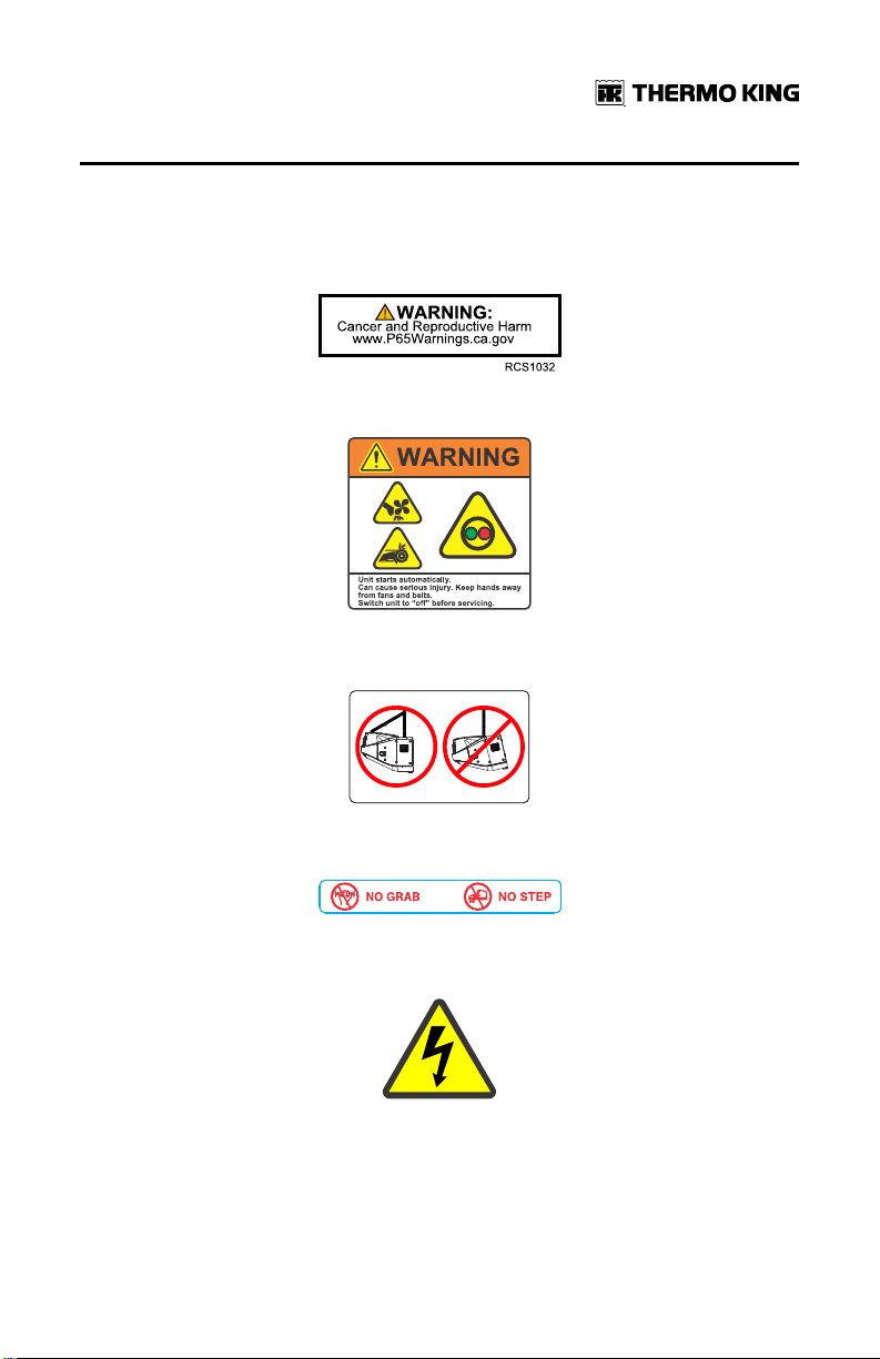
Safety Nameplates
Observe all safety nameplates placed in various locations on the unit.
Figure 1. Proposition 65 Nameplate
Figure 2. Automatic Start Warning Nameplate
Figure 3. Caution Lifting Nameplate
TK 56704-1-OP-EN
Figure 4. Caution No Grab No Step Nameplate
Figure 5. High Voltage Nameplate
15
Page 16

Unit Description
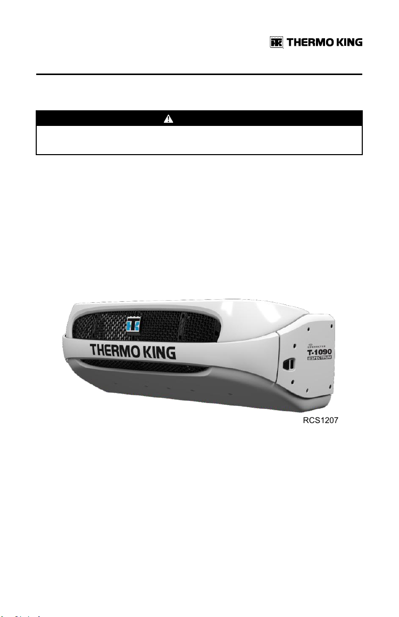
General Description
The T-1090 SPECTRUM™ is a self-powered multi-temperature cooling and
heating unit designed for straight trucks. The condensing unit is mounted on
the front of the truck cargo box. The remote evaporators are located in up to
three individual compartments inside the cargo box. The unit uses Chlorine
free R-404A refrigerant.
The basic models provide the following:
SSttaannddaarrdd UUnniitt ((MMooddeell 3300)):: Cooling and hot gas heating on engine
operation.
SSmmaarrttPPoowweerr™™ UUnniitt ((MMooddeell 5500)):: Cooling and hot gas heating on engine
operation and electric standby operation.
A three cylinder, EPA Tier 4, special clean and quiet diesel engine powers the
unit when in the truck is in route. SmartPower (Model 50) units are also
equipped with an electric motor for standby power operation while the truck
is stationary.
The SR-3 microprocessor based temperature control system and in-cab HMI
controller manage unit functions. CYCLE-SENTRY™, an exclusive Thermo
King feature, automatically starts and stops the unit according to
temperature demands. This continuous monitoring function optimizing the
unit’s performance and reduces fuel consumption while maintaining
temperature in multiple compartments.
The on-board Pretrip unit self check feature can be run before beginning the
daily distribution route to identify any possible unit malfunctions and help
prevent down time.
16
TK 56704-1-OP-EN
Page 17

UUnniitt DDeessccrriippttiioonn
Design Features
• Microprocessor Controlled
• Continuous System Monitoring
• In-Cab HMI Controller
• Alarm Code Display
• Battery Voltage Display
• Coolant Temperature Display
• CYCLE-SENTRY Start/Stop Controls
• Engine and Electric SmartPower (Model 50) Hour Meter
• OptiSet Plus Temperature Profiles
• Smart Defrost
• Unit Self Check-pretripping
• Aerodynamic Thermo Plastic Injection Molded Skins with In-mold Color
• Air Cleaner, Dry Type
• Alternator, 12 Volt, 37 Amp
• Bypass Oil Filter
• Coolant Expansion Tank
• Economy Mode
• Fahrenheit and Celsius Display
• Fuel Filter, Spin On
• Oil Filter, Full Flow
• Serpentine Belt with Manual Tensioner
• R-404A Chlorine-free Refrigerant
• Robotic Welded Steel Frame
• X214 Compressor (T-590 and T-690)
• X430P Compressor (T890, T-1090 and T-1090 SPECTRUM)
• ETV (Electronic Throttling Valve) (T-690, T-890, T-1090 and T-1090
SPECTRUM)
• TK374F Tier 4 Diesel Engine (T-590, T-690, and T-890)
• TK380F Tier 4 Diesel Engine (T-1090 and T-1090 SPECTRUM)
• USB Diagnostic Port
• TracKing™
TK 56704-1-OP-EN
17
Page 18

UUnniitt DDeessccrriippttiioonn
Unit Options
• Body Mount HMI Enclosure
• Door Switch
• MAX Cooling System
• Electric Evaporator Heaters
• SmartPower Electric Standby (Model 50)
• SmartPower Automatic Phase Correction (Model 50)
• SmartPower Diesel/Electric Autoswitching (Model 50)
• Engine Block Heater
• Fuel Tank (30 gallon aluminum, 18” and 22”)
• Quick Oil Drain Kit
• Rear Remote Control (flushmount)
• Remote Indicator Light
• Snow Cover
• Whisper™ Sound Kit
• Top Cover System
• Precision Temperature Control (all except T–590)
• TouchPrint
• Bluetooth
• Solar Panels
• Battery Box
• Evaporator Side Screens
18
TK 56704-1-OP-EN
Page 19

RCS1161
UUnniitt DDeessccrriippttiioonn
Engine
Engine power for the T-1090 SPECTRUM is provided by the TK380F, a three
cylinder, EPA Tier 4, special clean and quiet diesel engine rated at 19.3
continuous horsepower (14.4 kW) at 2425 RPM. A belt drive system transfers
energy to the compressor and alternator.
ELC (Extended Life Coolant)
The maintenance interval for ELC is eight years or 15,000 hours. A nameplate
near the coolant expansion tank identifies units with ELC. This coolant is Red
instead of the previous Green or Blue-Green coolants.
Figure 6. ELC (Extended Life Coolant) Nameplate
IImmppoorrttaanntt:: Only OAT extended life coolants (Chevron Delo® XLC or
equivalent) should be added to Thermo King systems.
Conventional coolants should not be used (Typically identified
by green or blue-green color). If a conventional coolant is
combined with the Thermo King factory fill up to 25% by volume,
the coolant must be changed at the next service opportunity.
Above 25%, the coolant must be changed immediately.
Conventional coolants dilute/interact with the additive packages
of extended life coolant which significantly reduces the service
life of the coolant.
NNoottee:: The use of 55/45% pre-mixed ELC is recommended to ensure that
deionized water is being used. If 100% full strength concentrate is
used, deionized or distilled water is recommended instead of tap
water to ensure the integrity of the cooling system is maintained.
Clutch
The centrifugal clutch engages fully at 600 ± 100 RPM on engine operation,
constantly turning the compressor, alternator, and fans at both high and low
TK 56704-1-OP-EN
19
Page 20

UUnniitt DDeessccrriippttiioonn
speed. The clutch isolates the engine from the belt drive system during
electric standby operation on Model 50 units.
Reciprocating Compressor
The T-1090 SPECTRUM features the X430P, 4 cylinder reciprocating
compressor with 30.0 cu in (492 cc) displacement.
HMI Controller
The HMI Controller communicates with the Base Controller (located inside
the control box) and is used operate the unit and display unit information. It
also provides access to all the controller functions and menus.
CYCLE-SENTRY™™ Start/Stop System
The CYCLE-SENTRY Start/Stop fuel saving system provides optimum
operating economy.
WWAARRNNIINNGG
RRiisskk ooff IInnjjuurryy!!
The unit can start at any time without warning. Press the OFF key on the
HMI control panel and place the microprocessor On/Off switch in the Off
position before inspecting or servicing any part of the unit.
The CYCLE-SENTRY system automatically starts the unit on microprocessor
demand and shuts down the unit when all demands are satisfied.
The system monitors and maintains the compartment temperature, the
engine block temperature, and battery charge levels at a point where quick,
easy starts are possible.
Defrost
Frost will gradually build up on the evaporator coils as a result of normal
operation. Periodically this frost must be melted to prevent a loss of cooling
and airflow.
Defrost is accomplished by passing hot refrigerant gas through the
evaporator coil, thus melting the frost (or ice). Melted frost drains out of the
unit onto the ground through the drain tubes.
Defrost can be initiated at any time the evaporator coil temperature is below
42 F (5.5 C).
20
TK 56704-1-OP-EN
Page 21

UUnniitt DDeessccrriippttiioonn
There are two methods of defrost initiation:
SSRR--22//SSRR--33 MMiiccrroopprroocceessssoorr CCoonnttrroolllleerr:: The Microprocessor Controller is
programmed to automatically initiate timed and forced defrost cycles. The
SR-2/SR-3 uses temperature sensors to determine if forced defrost is
required.
MMaannuuaall DDeeffrroosstt:: Manual Defrost allows the operator to initiate a defrost
cycle by pressing the Defrost key. See “Initiating a Manual Defrost Cycle.”
TracKing™
T-90 series units are equipped with a wireless communication platform that
offers fleet owners the ability to monitor their refrigerated units. Cellular,
GPS, and Bluetooth capabilities communicate with Thermo King’s webbased TracKing™ application, and Bluetooth with the Thermo King Reefer
App. A third party interface offers a gateway for telematics providers to
communicate with the Thermo King unit. To learn more about the TracKing
features, contact your Thermo King dealer.
SmartPower Electric Standby (Model 50 Units Only)
The SmartPower Electric Standby option allows the unit to be operated on
either the diesel engine or external electric power.
DDAANNGGEERR
HHaazzaarrddoouuss VVoollttaaggee!!
High voltage AC power is present whenever the unit is operating in the
Electric Standby mode and whenever the unit is connected to external
standby power. Voltages of this magnitude can be lethal. Exercise extreme
caution when working on the unit.
SmartPower Standard Features
The following features are standard equipment on units equipped with
SmartPower Electric Standby.
AAuuttoommaattiicc DDiieesseell//EElleeccttrriicc SSeelleeccttiioonn:: The unit will automatically switch to
electric operation when a power cord is connected and the standby power is
switched On.
OOvveerrllooaadd RReellaayy:: The overload relay is self-resetting.
HHoott GGaass HHeeaatt:: Hot gas heat is utilized on all units.
TK 56704-1-OP-EN
21
Page 22

UUnniitt DDeessccrriippttiioonn
AAuuttoommaattiicc PPhhaassee CCoorrrreeccttiioonn:: The control system features two motor
contactors. This allows correct motor rotation regardless of phase rotation
on the incoming power.
SmartPower Optional Features
The following features are available as options on units equipped with
Electric Standby.
• Auto Switching
Unit Protection Devices
HHiigghh PPrreessssuurree CCuuttoouutt SSwwiittcchh ((HHPPCCOO)):: This normally closed switch
monitors the discharge pressure at the compressor. It opens on high
discharge pressure to shut the unit down to prevent damage.
EElleeccttrroonniicc TThhrroottttlliinngg VVaallvvee ((EETTVV)):: This component is an electromechanical
control device used to limit the suction pressure to the compressor. The
valve is controlled by the microprocessor controller.
EEnnggiinnee OOiill PPrreessssuurree SSwwiittcchh//SSeennssoorr:: The engine oil pressure switch/sensor
is located on the filter head above the bypass oil filter. Engine oil pressure
should rise immediately on starting. If engine oil pressure drops below 10 ±
2 psig (69 ± 14 kPa), the switch/sensor signals the microprocessor to stop the
engine.
PPrreehheeaatt BBuuzzzzeerr:: The preheat buzzer sounds when the CYCLE-SENTRY
system energizes the glow plugs. This should warn anyone near the unit that
the CYCLE-SENTRY system is about to start the diesel engine.
CCoooollaanntt TTeemmppeerraattuurree SSeennssoorr:: This sensor provides an engine coolant
temperature input to the microprocessor. If the engine coolant temperature
is too high, the controller stops the unit and records an alarm.
EElleeccttrriicc MMoottoorr OOvveerrllooaadd RReellaayy ((MMooddeell 5500)):: The overload relay protects the
electric standby motor. The overload relay opens the circuit from the
contactor to the electric motor if the motor overloads for any reason and an
alarm will occur. The relay resets when the alarm code is cleared.
FFuusseess:: Sizes and functions are described in the Specifications chapter of this
manual.
Engine Compartment Components
CCoooollaanntt EExxppaannssiioonn TTaannkk:: The coolant level and temperature are monitored
by the base controller. If the coolant temperature becomes too high or the
level becomes too low, an alarm will occur.
22
TK 56704-1-OP-EN
Page 23
RCS1207
UUnniitt DDeessccrriippttiioonn
The engine must have antifreeze protection to –30 F (–34 C). Check and add
coolant in the expansion tank as needed.
CCAAUUTTIIOONN
HHaazzaarrddoouuss PPrreessssuurreess!!
Do not remove expansion tank cap while coolant is hot.
EEnnggiinnee OOiill DDiippssttiicckk:: Use the engine oil dipstick to check the engine oil level.
RReecceeiivveerr TTaannkk SSiigghhtt GGllaassss:: The receiver tank sight glass is used to assist in
checking the amount of refrigerant in the system.
CCoommpprreessssoorr OOiill SSiigghhtt GGllaassss:: The compressor oil sight glass is used to
check the relative level of compressor oil in the compressor sump.
Unit Components
Figure 7. Front View of Unit
TK 56704-1-OP-EN
23
Page 24

1
2
3
4
5
6
7
8
9
RCS1141
UUnniitt DDeessccrriippttiioonn
Figure 8. Engine Compartment Components
1. Engine Oil Dipstick (on side of
engine)
2. Engine 7. Dehydrator (Filter-Drier)
3. Coolant Expansion Tank 8. Compressor
4.
Coolant Overflow Bottle
5. Electric Motor
24
6. Alternator
9.
Base Controller On/Off Switch
TK 56704-1-OP-EN
Page 25
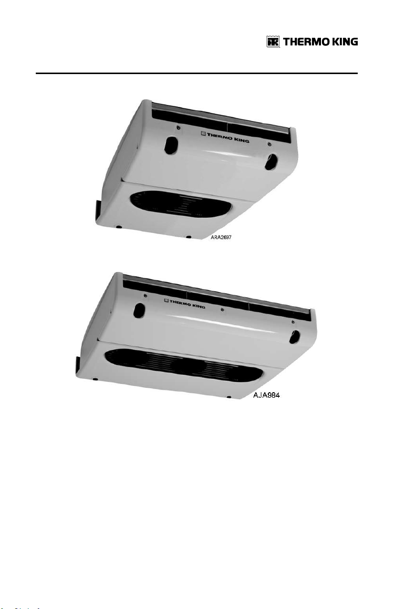
UUnniitt DDeessccrriippttiioonn
Figure 9. S-2 Remote Evaporator – Front View
Figure 10. S-3 Remote Evaporator – Front View
TK 56704-1-OP-EN
25
Page 26
Operating Instructions for Premium HMI Control Panel
Truck Premium Display HMI Control Panel
The Truck Premium Display is used to operate the unit, display unit
information, and access all Maintenance and Guarded Access Menus. The
Truck Premium Display communicates with the Base Controller via the
Controller Area Network (CAN) bus. It is connected to the Base Controller via
CAN Connector J14 on the interface board. The Truck Premium Display is
typically located in the vehicle driver’s compartment. It may be installed in
the truck instrument panel using a DIN mounting ring or under the
instrument panel using an under dash mounting kit.
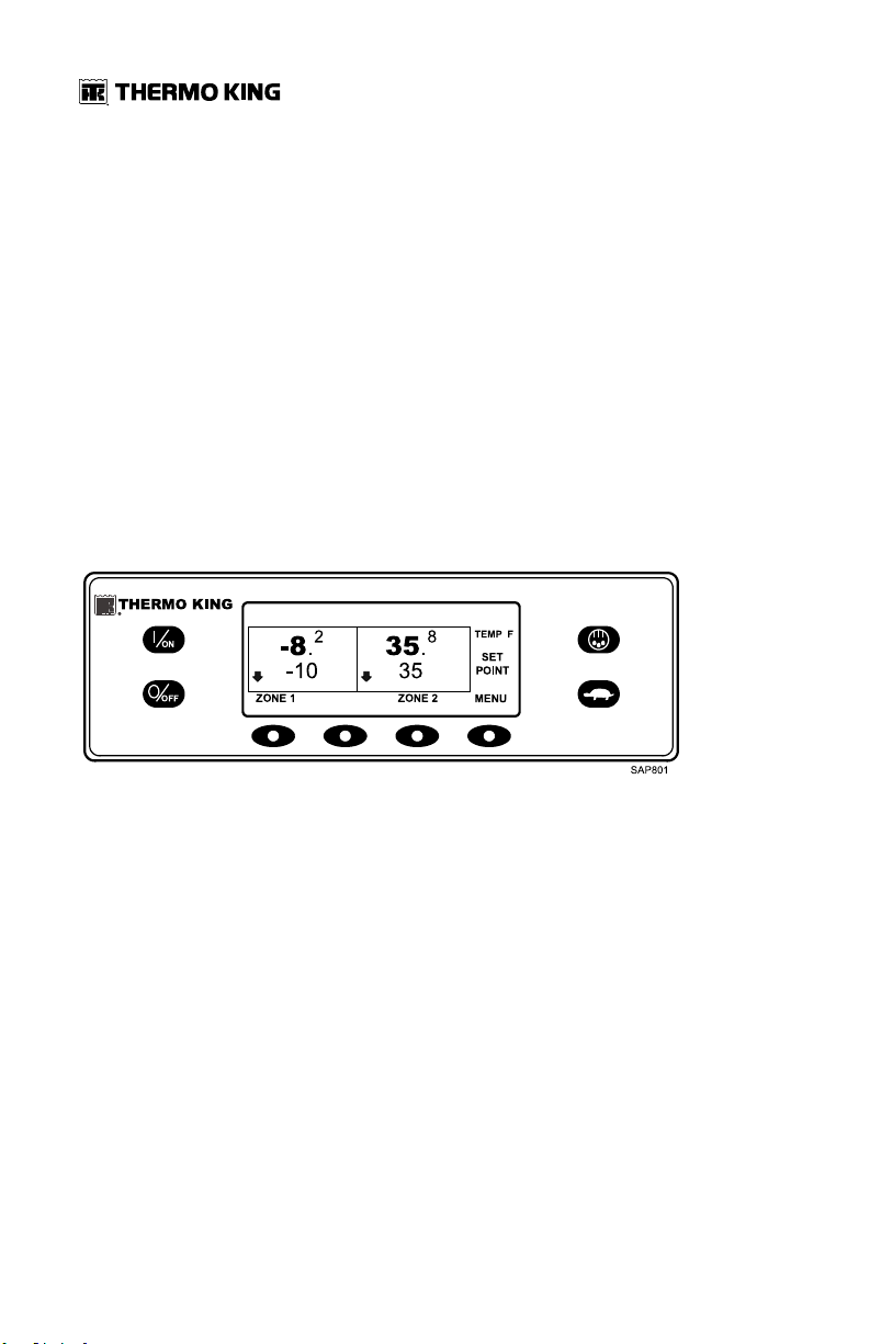
Figure 11. Truck Premium HMI Control Panel
The HMI control panel consists of a display and 8 touch-sensitive keys.
The display is capable of showing both text and graphics.
The keys on the left and right sides of the display are dedicated single
function “hard” keys.
The four keys under the display are “soft” keys. The functions of these soft
keys change depending on the operation being performed. If a soft key is
active the current key function is shown in the display directly above the key.
Display
The display presents information to the operator. This information includes
setpoint and temperature for each zone, unit or zone operating information,
gauge readings, temperatures, and other information as selected by the
operator.
26
TK 56704-1-OP-EN
Page 27
OOppeerraattiinngg IInnssttrruuccttiioonnss ffoorr PPrreemmiiuumm HHMMII CCoonnttrrooll PPaanneell
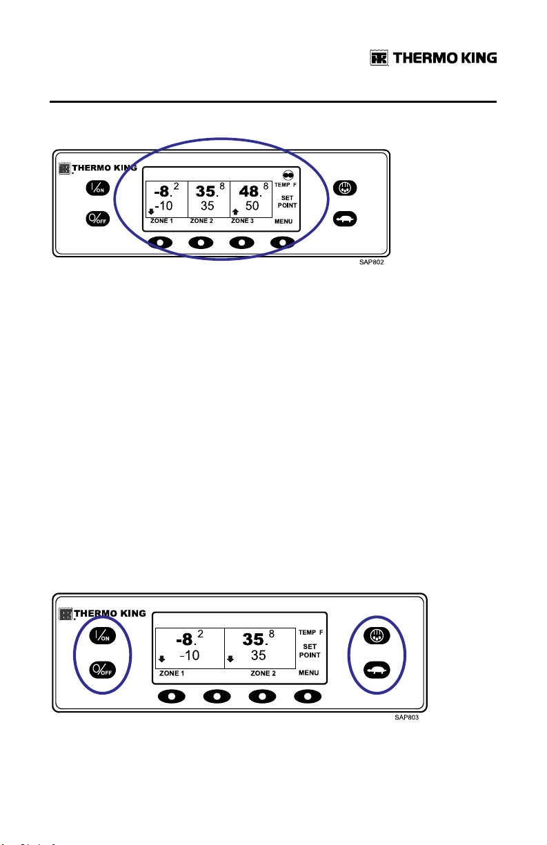
Figure 12. Display
The Standard Display of box temperature and setpoint for three zones is
shown (Figure 12, p. 27). The Cycle Sentry Icon in the upper right of the
display shows the unit is running in Cycle Sentry Mode. Zone 1 has a
setpoint of -10°F, and a return air temperature of -8.2°F. The downward
pointing arrow shows this zone is cooling. Zone 2 has a setpoint of 35°F, and
a return air temperature of 35.8°F. The absence of an arrow indicates that
this zone is in null. Zone 3 has a setpoint of 50°F, and a return air
temperature of 48.8°F. The upward pointing arrow shows this zone is
heating.
NNoottee:: The zone temperature shown is always return air temperature.
The four keys under the display are termed “soft” keys. The functions of
these keys change depending on the operation being performed. The
function of each soft key is shown by labels in the display located directly
above each soft key. The soft key under each zone is used to turn that zone
on and off and allows the Setpoint for that zone to be changed. Pressing the
soft key under MENU accesses the MAIN MENU.
Hard Keys
Figure 13. Hard Keys
TK 56704-1-OP-EN
27
Page 28
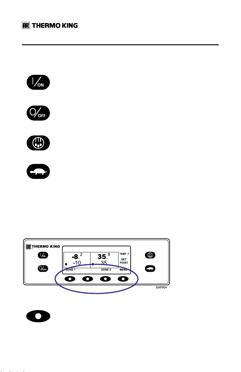
OOppeerraattiinngg IInnssttrruuccttiioonnss ffoorr PPrreemmiiuumm HHMMII CCoonnttrrooll PPaanneell
The keys on either side of the display are dedicated or "hard" keys. Their
function always remains the same.
This key is used to turn the unit on. First the display will briefly show the
Thermo King Logo and then the statement "Configuring System - Please
Wait". When the power-up sequence is complete the display shows the
Standard Display of box temperature and setpoint. For more information
see "Turning the Unit On and Off" later in this section.
This key is used to turn the unit off. First the display will briefly show
"System is Powering Down - Please Wait. Press On to Resume" and then
"Off" will appear momentarily. When the power-down sequence is
complete the display will be blank. For more information see "Turning the
Unit On and Off" later in this section.
This key is used to initiate a manual defrost cycle. For more information
see "Initiating a Manual Defrost Cycle" later in this section.
This key is used to lock out high speed operation in noise sensitive areas.
For more information see "Selecting High Speed Lockout" later in this
section.
Note: The Thermo King Premium Truck HMI Control Panel features a High
Speed Lock-Out key as shown here. The Thermo King Truck HMI
Control Panel features a Cycle Sentry key in this position. When
using the Thermo King Premium Truck HMI Control Panel, Cycle
Sentry Mode or Continuous Mode is selected from the Main Menu –
Mode Submenu as shown later in this section.
Soft Keys
Figure 14. Soft Keys
The four "soft" keys under the display are multi-purpose keys. Their
function changes depending on the operation being performed. If a soft
key is active the key function is shown in the display directly above the
key. The keys are numbered from left to right, with Key 1 on the far left
and Key 4 on the far right.
28
TK 56704-1-OP-EN
Page 29
OOppeerraattiinngg IInnssttrruuccttiioonnss ffoorr PPrreemmiiuumm HHMMII CCoonnttrrooll PPaanneell
Typical soft key functions:
ZONE ON/OFF and SETPOINT CHANGE
MENU + or - HOURMETERS EXIT
NEXT SELECT GAUGES HELP
YES/NO CLEAR BACK SENSORS
Turning the Unit On and Off
IImmppoorrttaanntt:: Verify the Base Controller On/Off Switch is turned on before
turning on the HMI Control Panel. The Base Controller On/Off
switch is located on the outside of the control box side of the
unit.
If the HMI Control Panel is turned on and the Base Controller On/Off Switch
is turned off, the HMI display screen will briefly show LOST CONTROLLER
POWER. The HMI will then power down.
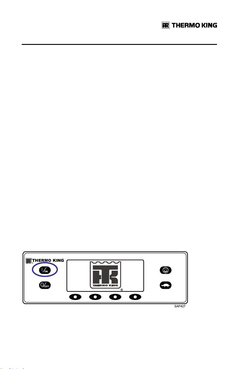
The unit is turned on by pressing the ON key and off by pressing the OFF
key. When the ON key is pressed, the display briefly shows the THERMO
KING Logo as the display initializes.
IImmppoorrttaanntt:: The ON key must be held down until the Thermo King Logo
appears as shown (Figure 15, p. 29). If the ON key is not held
down long enough (approximately ½ second), the display may
flicker but the unit will not start up. If this occurs, hold the ON key
down until the Thermo King logo appears.
NNoottee:: With extremely cold ambient temperatures, it may take up to 15
seconds for the display to appear on initial startup.
Figure 15. ON Key
The startup screen shown (Figure 16, p. 30) appears while communications
are established and the unit prepares for operation.
TK 56704-1-OP-EN
29
Page 30
OOppeerraattiinngg IInnssttrruuccttiioonnss ffoorr PPrreemmiiuumm HHMMII CCoonnttrrooll PPaanneell
Figure 16. Startup Screen
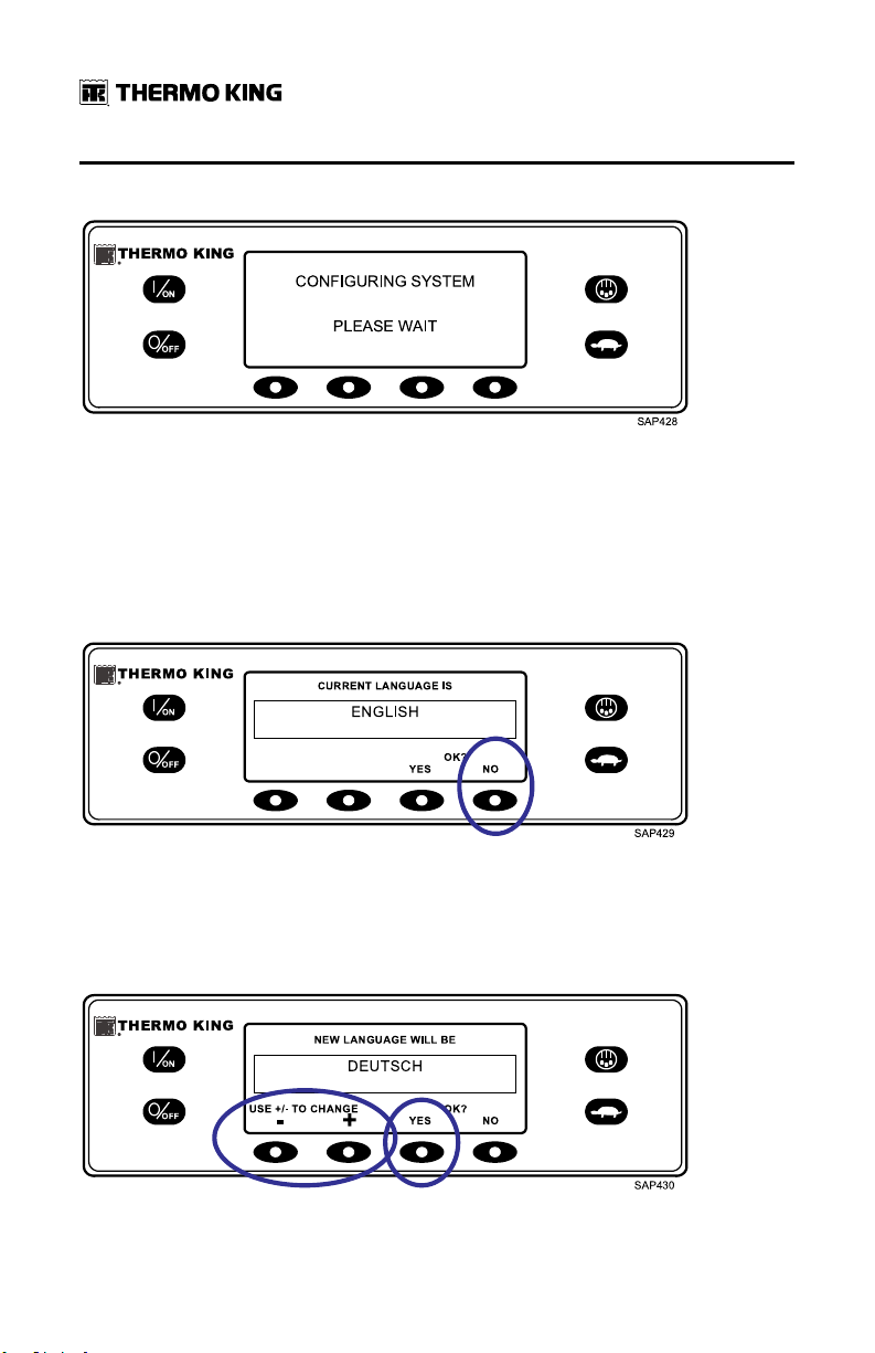
If More Than One Language is Enabled
If more than one language has been enabled, a prompt will appear to allow
the desired language to be chosen as shown (Figure 17, p. 30). Only
languages enabled from the Guarded Access Menu are available. If a
different language is desired, press the NO key.
Figure 17. NO key
The Language menu will appear as shown (Figure 18, p. 30). Press the + or keys to select the desired language. When the desired language is shown,
press the YES key to confirm the choice.
Figure 18. YES Key
30
TK 56704-1-OP-EN
Page 31

OOppeerraattiinngg IInnssttrruuccttiioonnss ffoorr PPrreemmiiuumm HHMMII CCoonnttrrooll PPaanneell
The display will briefly show PROGRAMMING LANGUAGE - PLEASE WAIT
in the new language as shown (Figure 19, p. 31).
Figure 19. Programming Language
The new language is confirmed, and the Standard Display will appear in the
new language as shown (Figure 20, p. 31). The unit is ready to run.
Figure 20. Truck Premium HMI Control Panel
Should it be necessary to change to another language at any time, return to
the Standard Display and then press and hold the first and last soft keys for
five seconds as shown (Figure 21, p. 31). The Standard Display below is
shown in Deutsch (German).
Figure 21. First and Last Soft Keys
TK 56704-1-OP-EN
31
Page 32

OOppeerraattiinngg IInnssttrruuccttiioonnss ffoorr PPrreemmiiuumm HHMMII CCoonnttrrooll PPaanneell
The Language menu will appear in the current language as shown (Figure
22, p. 32). Press the + or - keys to select the desired language. When the
desired language is shown, press the YES key to confirm the choice. All
languages in the installed software can be selected using this method.
Figure 22. Language Menu
When the unit is ready to run, the Standard Display appears.
Figure 23. Standard Display
Pressing the OFF key stops unit operation. The unit shuts down immediately
and the display briefly shows the power down message.
Figure 24. Power Down Message
32
TK 56704-1-OP-EN
Page 33

OOppeerraattiinngg IInnssttrruuccttiioonnss ffoorr PPrreemmiiuumm HHMMII CCoonnttrrooll PPaanneell
The display briefly shows OFF and then goes blank. To start the unit again,
press the ON key.
Figure 25. Off Display
The Standard Display
The Standard Display is the default display that appears if no other display
function is selected. The Standard Display shows the box temperature and
setpoint. The box temperature is that measured by the controlling sensor,
usually the return air sensor. The box temperature shown is 35.8°F with a 35°
F setpoint.
Figure 26. Standard Display
The CYCLE-SENTRY Icon in the upper right corner of the display shows that
the unit is operating in CYCLE-SENTRY Mode. If the CYCLE-SENTRY Icon is
not present, the unit is operating in Continuous Mode.
The down-pointing arrow indicates that the unit is cooling. If the unit was
heating, the arrow would be pointing upward.
Pressing the left soft key allows the user to change the SETPOINT, and
pressing the right soft key accesses the MAIN MENU. The other two soft
keys access the GAUGES menu and the SENSORS menu.
TK 56704-1-OP-EN
33
Page 34

OOppeerraattiinngg IInnssttrruuccttiioonnss ffoorr PPrreemmiiuumm HHMMII CCoonnttrrooll PPaanneell
Changing the Setpoint
From the Standard Display, press the ZONE soft key for the desired zone.
ZONE 2 is shown (Figure 27, p. 34).
Figure 27. Zone Key
The setpoint display appears as shown (Figure 28, p. 34).
Figure 28. Setpoint Display
The - and + soft keys are used to increase or decrease the setpoint until the
desire setpoint is shown. The setpoint has been changed to 40°F using the +
key (Figure 29, p. 34).
Figure 29. Increase Setpoint
34
TK 56704-1-OP-EN
Page 35

OOppeerraattiinngg IInnssttrruuccttiioonnss ffoorr PPrreemmiiuumm HHMMII CCoonnttrrooll PPaanneell
The YES and NO soft keys confirm the setpoint change. When the desired
setpoint has been selected using the + and/or - keys, press the YES soft key
to confirm and load the new setpoint. If the setpoint is changed using the +
or - keys, the change must be confirmed or rejected by pressing the YES or
NO soft key within 10 seconds of changing the setpoint.
Failure to confirm the new setpoint by pressing YES or NO within 10 seconds
of changing the setpoint will result in no setpoint change. In addition, Alarm
Code 127 Setpoint Not Entered is set, to indicate that the setpoint change
was not completed.
Figure 30. YES/NO Soft Keys
After the YES soft key has been pressed, the display briefly shows
PROGRAMMING NEW SETPOINT - PLEASE WAIT. The display then confirms
the new setpoint for several seconds.
Figure 31. New Setpoint
If the NO soft key is pressed, the display will briefly show SETPOINT NOT
CHANGED and return to the Standard Display. The Standard Display will
show the old setpoint. The display then returns to the Standard Display
showing the new setpoint. The arrow now points up to indicate that the unit
is heating (Figure 32, p. 36). The Zone 2 arrow now points up, to indicate that
Zone 2 is heating.
TK 56704-1-OP-EN
35
Page 36

OOppeerraattiinngg IInnssttrruuccttiioonnss ffoorr PPrreemmiiuumm HHMMII CCoonnttrrooll PPaanneell
IImmppoorrttaanntt:: If the setpoint is changed using the + or - keys, the change must
be confirmed or rejected by pressing the YES or NO soft key
within 10 seconds of changing the setpoint.
• If the YES key is pressed, the setpoint change made with the + or - key is
accepted, the setpoint changes, and the display returns to the Standard
Display.
• If the NO key is pressed, the setpoint change made with the + or - key is
not accepted, the setpoint is not changed, and the display returns to the
Standard Display.
• If either the YES or NO key is not pressed within 10 seconds of making a
change with the + or - key, the setpoint is not changed, and the display
returns to the Setpoint Display. The display briefly shows [SETPOINT
NOT CHANGED] and Alarm Code 127 Setpoint Not Entered is set, to
indicate that a setpoint change was started but not completed.
Figure 32. Standard Display, New Setpoint
Starting the Diesel Engine
CCAAUUTTIIOONN
RRiisskk ooff IInnjjuurryy!!
The engine may start automatically any time the unit is turned on.
NNOOTTIICCEE
EEqquuiippmmeenntt DDaammaaggee!!
Never use starting fluid. Damage to the engine can occur.
Diesel engine preheats and starts are automatic in both Continuous Mode
and CYCLE-SENTRY Mode. The engine will preheat and start as required
when the unit is turned on. The engine preheat and start will be delayed in
CYCLE-SENTRY mode if there is no current need for the engine to run. If any
36
TK 56704-1-OP-EN
Page 37

OOppeerraattiinngg IInnssttrruuccttiioonnss ffoorr PPrreemmiiuumm HHMMII CCoonnttrrooll PPaanneell
keys are being pressed on the HMI Control Panel, the engine will not preheat
and start until 10 seconds after the last key is pressed.
NNoottee:: If the unit is equipped with optional Electric Standby, there may be
some additional prompts before the engine will start. Refer to Starting
the Electric Motor for details.
When the engine is preparing to start, the HMI Control Panel will display the
engine start screen (Figure 33, p. 37). The preheat buzzer sounds during the
engine preheat and crank sequence.
Figure 33. Engine Start Screen
After the engine is started, the display returns to the Standard Display of
temperature and setpoint.
Starting the Electric Motor
NNoottee:: Units equipped with the Electric Standby option only.
CCAAUUTTIIOONN
RRiisskk ooff IInnjjuurryy!!
The motor may start automatically any time the unit is turned on.
TK 56704-1-OP-EN
37
Page 38

OOppeerraattiinngg IInnssttrruuccttiioonnss ffoorr PPrreemmiiuumm HHMMII CCoonnttrrooll PPaanneell
Electric motor starting is automatic in both Continuous Mode and CYCLESENTRY Mode. The motor will start as required when the unit is turned on. If
any keys are being pressed on the HMI Control Panel prior to the motor start,
the motor start will be delayed until 10 seconds after the last key is pressed.
When the motor is preparing to start, the HMI Control Panel will display the
motor start screen (Figure 34, p. 38). The preheat buzzer sounds for 20
seconds before the electric motor starts.
Figure 34. Motor Start Screen
After the motor is running, the display returns to the Standard Display of
temperature and setpoint.
Switching from Diesel to Electric
NNoottee:: Units equipped with the Electric Standby option only.
If the Diesel to Electric Autoswitch Enabled feature in Guarded Access is set
YES, the unit will automatically switch to Electric Mode operation when
standby power is connected and available.
If the Diesel to Electric Autoswitch Enabled feature in Guarded Access is set
NO, the prompt screen shown (Figure 35, p. 39) will appear when standby
power is connected and available.
38
TK 56704-1-OP-EN
Page 39

OOppeerraattiinngg IInnssttrruuccttiioonnss ffoorr PPrreemmiiuumm HHMMII CCoonnttrrooll PPaanneell
Figure 35. Prompt Screen
If YES is selected, the display will briefly show the screen below (Figure 36,
p. 39).
Figure 36. Programming Screen
Electric Mode operation will briefly be confirmed. If unit operation is
required, the electric motor will start as shown in Starting The Electric Motor.
Switching from Electric to Diesel
NNoottee:: Units equipped with the Electric Standby option only.
If the Electric to Diesel Autoswitch Enabled feature in Guarded Access is set
YES, the unit will automatically switch to Diesel Mode operation when
standby power is turned off or is no longer available.
If the Electric to Diesel Autoswitch Enabled feature in Guarded Access is set
NO, the prompt screen (Figure 37, p. 40) will appear when standby power is
turned off or is no longer available. Alarm Code 91 Check Electric Ready
Input and Alarm Code 84 Restart Null will both be set.
TK 56704-1-OP-EN
39
Page 40

OOppeerraattiinngg IInnssttrruuccttiioonnss ffoorr PPrreemmiiuumm HHMMII CCoonnttrrooll PPaanneell
Figure 37. Prompt Screen
Turn the unit off and back on using the OFF and ON Keys. This will clear
Alarm Code 91 Check Electric Ready Input and Alarm Code 84 Restart Null.
NNoottee:: The CLEAR Soft Key will not clear these two alarms. The prompt
screen shown (Figure 38, p. 40) will appear.
Figure 38. Prompt Screen
If YES is selected, the display will briefly show the programming screen
(Figure 39, p. 40). Diesel Mode operation will briefly be confirmed.
Figure 39. Programming Screen
40
TK 56704-1-OP-EN
Page 41

OOppeerraattiinngg IInnssttrruuccttiioonnss ffoorr PPrreemmiiuumm HHMMII CCoonnttrrooll PPaanneell
If unit operation is required, the diesel engine will start as shown previously
in Starting The Diesel Engine.
Initiating a Manual Defrost Cycle
Defrost cycles are usually initiated automatically based on time or demand.
Manual defrost is only available if the zone is running and the zone
evaporator coil temperature is less than or equal to 45°F (7°C). Other features
such as door switch settings may not allow manual defrost under some
conditions.
To initiate a manual defrost cycle, press the Defrost Key as shown (Figure
40, p. 41).
Figure 40. Defrost Key
The display will briefly show [DEFROST]. The Zone Select display will
appear. Zone 1 has been selected (Figure 41, p. 41).
Figure 41. Select Zone
The display briefly shows [DEFROST], [PROGRAMMING DEFROST - PLEASE
WAIT] and then [DEFROST STARTED].
TK 56704-1-OP-EN
41
Page 42

OOppeerraattiinngg IInnssttrruuccttiioonnss ffoorr PPrreemmiiuumm HHMMII CCoonnttrrooll PPaanneell
Figure 42. Defrost Started
The display then shows the Defrost display. The bar indicator shows
approximately the percentage of time remaining to complete the defrost
cycle. The bar indicator (Figure 43, p. 42) shows that the Zone 1 defrost cycle
is approximately 25% complete.
Figure 43. Defrost Display
Terminating a Defrost Cycle
The defrost cycle terminates automatically when the coil temperature is
greater than or equal to 52°F (11°C) or the defrost timer expires. Defrost can
also be terminated by turning the unit off and back on.
Selecting High Speed Lockout Mode (If Enabled)
High speed operation can be locked out in noise sensitive areas if required.
NNoottee:: High Speed Lockout Enable must be set to [Enabled] in the Guarded
Access/Programmable Features Menu or this feature will not be
available.
42
TK 56704-1-OP-EN
Page 43

OOppeerraattiinngg IInnssttrruuccttiioonnss ffoorr PPrreemmiiuumm HHMMII CCoonnttrrooll PPaanneell
IImmppoorrttaanntt:: HIGH SPEED LOCKOUT TIMEOUT: If High Speed Lockout Mode
is selected, the High Speed Inhibit Timeout feature may be set to
return the unit to normal operation after a set time period has
expired. This prevents extended operation with high speed
operation locked out. The time period may be from 15 minutes to
2 hours. If the time period is set and is exceeded, the unit will
return to normal operation, with high speed operation allowed. If
this occurs, the message HIGH SPEED LOCKOUT ACTIVE at the
top of the display will disappear. If necessary to return to High
Speed Lockout Mode, press the High Speed Lockout Key again.
The High Speed Lockout Key is a toggle. If high speed is currently allowed,
pressing the High Speed Lockout Key will disable high speed operation.
Pressing the High Speed Lockout Key again will allow high speed operation.
To change the setting, press the High Speed Lockout key as shown (Figure
44, p. 43).
Figure 44. High Speed Lockout Key
The display will briefly show [PROGRAMMING HIGH SPEED LOCKOUT PLEASE WAIT].
Figure 45. Programming Screen
TK 56704-1-OP-EN
43
Page 44

OOppeerraattiinngg IInnssttrruuccttiioonnss ffoorr PPrreemmiiuumm HHMMII CCoonnttrrooll PPaanneell
The change is confirmed by briefly displaying [HIGH SPEED LOCKOUT
ACTIVE] or [HIGH SPEED LOCKOUT INACTIVE].
Figure 46. High Speed Lockout Display
The display will then return to the Standard Display. If High Speed Lockout is
turned on, the message HIGH SPEED LOCKOUT ACTIVE will be shown at the
top of the display.
Figure 47. High Speed Lockout Active
Pressing the High Speed Lockout key again will turn the feature off.
Using the Gauges Key
The GAUGES key allows the operator to view the unit gauges. To access the
GAUGES menu press the GAUGES key.
44
TK 56704-1-OP-EN
Page 45

OOppeerraattiinngg IInnssttrruuccttiioonnss ffoorr PPrreemmiiuumm HHMMII CCoonnttrrooll PPaanneell
Figure 48. Gauges Key
The first gauge display will appear. Press the NEXT and BACK keys to scroll
through the gauges. The Battery Voltage Gauge is shown (Figure 49, p. 45).
Press the LOCK key to lock the selected gauge on the display.
Figure 49. Next, Back, Lock Keys
The gauges and I/O conditions available are shown below. The order in
which the gauges appear may vary slightly based on software revision. Not
all gauges may appear, depending on unit configuration and software
revision.
To return to the Standard Display press the EXIT key.
Gauges Available
CCoooollaanntt TTeemmppeerraattuurree:: Displays the temperature of the engine coolant.
CCoooollaanntt LLeevveell:: Displays the coolant level in the overflow tank as OK or
LOW.
EEnnggiinnee OOiill PPrreessssuurree:: Displays the engine oil pressure as OK or LOW.
EEnnggiinnee OOiill LLeevveell:: Displays the engine oil level as OK or LOW.
AAmmppss:: Displays the current flow in amps flowing to or from the unit battery.
BBaatttteerryy VVoollttaaggee:: Displays the voltage of the unit battery.
TK 56704-1-OP-EN
45
Page 46

OOppeerraattiinngg IInnssttrruuccttiioonnss ffoorr PPrreemmiiuumm HHMMII CCoonnttrrooll PPaanneell
EEnnggiinnee RRPPMM:: Displays the engine speed in RPMs.
DDiisscchhaarrggee PPrreessssuurree:: Displays the unit discharge pressure.
SSuuccttiioonn PPrreessssuurree:: Displays the unit suction pressure.
EETTVV PPoossiittiioonn:: Displays the current position of the ETV valve. ETV units only.
CCoommpprreessssoorr TTeemmppeerraattuurree:: Displays the temperature sensed by the
compressor temperature sensor. Scroll compressor only.
II//OO ((IInnppuutt//OOuuttppuutt SSttaattee)):: Displays the current state of the input/output
devices (ON or OFF) listed here:
High Speed Relay/Electric
Heat
Run Relay Alternator Frequency Drain Hose Heater
Run Relay Feedback Diesel/Electric Relay (Model 50
Alternator Excite Output Electric Ready Input (Model 50
Defrost Damper Electric Overload (Model 50 units
Hot Gas Solenoid Condenser Inlet
Solenoid
Purge Valve
units only)
units only)
only)
Using the Sensors Key
The SENSORS key allows the operator to view the temperatures read by the
unit temperature sensors. To access the SENSORS menu press the
SENSORS key.
Figure 50. Sensors Key
The first sensor display will appear. Press the NEXT and BACK keys to scroll
through the sensors. The Discharge Air Temperature sensor is shown
(Figure 51, p. 47). Press the LOCK key to lock the current sensor on the
display.
46
TK 56704-1-OP-EN
Page 47

OOppeerraattiinngg IInnssttrruuccttiioonnss ffoorr PPrreemmiiuumm HHMMII CCoonnttrrooll PPaanneell
Figure 51. Next, Back, Lock Keys
The sensors available are shown below. To return to the Standard Display
press the EXIT key.
Sensors Available
RReettuurrnn AAiirr TTeemmppeerraattuurree:: Displays the temperature of the control return air
sensor.
DDiisscchhaarrggee AAiirr TTeemmppeerraattuurree:: Displays the temperature of the control
discharge air sensor.
TTeemmppeerraattuurree DDiiffffeerreennttiiaall:: Displays the calculated difference between the
control return air sensor and the control discharge air sensor.
EEvvaappoorraattoorr CCooiill TTeemmppeerraattuurree:: Displays the temperature of the evaporator
coil sensor.
AAmmbbiieenntt AAiirr TTeemmppeerraattuurree:: Displays the temperature of the ambient air
sensor.
SSppaarree 11 TTeemmppeerraattuurree:: Displays the temperature of the spare 1 temperature
sensor.
DDaattaa LLooggggeerr SSeennssoorr 11 TTeemmppeerraattuurree:: Displays the temperature of the Data
Logger sensor 1.
DDaattaa LLooggggeerr SSeennssoorr 22 TTeemmppeerraattuurree:: Displays the temperature of the Data
Logger sensor 2.
DDaattaa LLooggggeerr SSeennssoorr 33 TTeemmppeerraattuurree:: Displays the temperature of the Data
Logger sensor 3.
DDaattaa LLooggggeerr SSeennssoorr 44 TTeemmppeerraattuurree:: Displays the temperature of the Data
Logger sensor 4.
DDaattaa LLooggggeerr SSeennssoorr 55 TTeemmppeerraattuurree:: Displays the temperature of the Data
Logger sensor 5.
TK 56704-1-OP-EN
47
Page 48

OOppeerraattiinngg IInnssttrruuccttiioonnss ffoorr PPrreemmiiuumm HHMMII CCoonnttrrooll PPaanneell
DDaattaa LLooggggeerr SSeennssoorr 66 TTeemmppeerraattuurree:: Displays the temperature of the Data
Logger sensor 6.
Using The Main Menu
The Main Menu contains several additional submenus that allow the
operator to view information and modify unit operation. To access the Main
Menu press the MENU key.
Figure 52. Menu Key
The first Main Menu choice will appear. Press the NEXT and BACK keys to
scroll through the menu choices. When the desired selection is shown on the
display, press the SELECT key to access it. The Pretrip submenu is shown
(Figure 53, p. 48). To return to the Standard Display press the EXIT key.
Figure 53. Pretrip Submenu
Main Menu Choices
LLaanngguuaaggee MMeennuu:: If more than one language is enabled, this will be the first
menu item to appear. If only one language is enabled, this menu will not
appear. The Language Menu allows the operator to select a language from a
list of up to 11 languages at one time. All subsequent displays are shown in
the selected language. Three different language packages with a total of 23
48
TK 56704-1-OP-EN
Page 49

OOppeerraattiinngg IInnssttrruuccttiioonnss ffoorr PPrreemmiiuumm HHMMII CCoonnttrrooll PPaanneell
languages are available. English is the default language and is provided in
each of the packages.
AAllaarrmmss MMeennuu:: Allows the operator to view all alarms, and allows most
alarms to be cleared. If only one language is enabled, this will be the first
menu item to appear.
GGaauuggeess MMeennuu:: Allows the operator to view the unit gauges and the state of
the Inputs and Outputs on both the Interface Board and the Expansion
Module.
SSeennssoorrss MMeennuu:: Allows the operator to view the unit temperature sensors. If
a DAS Data Logger is installed, the data logger sensors may also be viewed.
DDaattaa LLooggggeerr MMeennuu:: Allows the operator to send a Start of Trip marker to the
ServiceWatch Data Logger and the optional DAS Data Logger (if installed). A
Print request can also be sent to the optional DAS Data Logger (if installed)
to print the most recent trip record.
HHoouurrmmeetteerrss MMeennuu:: Allows the operator to view the unit hourmeters that
have the view feature enabled in the Guarded Access Menu. If the view
feature for a particular hourmeter is not enabled, that hourmeter will
continue to accumulate time but cannot be viewed from the Main Menu.
However, all hourmeters can be viewed from the Maintenance Menu, even if
they are not enabled.
MMooddee MMeennuu:: Allows the operator to change the unit operating modes if
allowed. Not all modes may appear depending on the settings selected from
the Guarded Access menu and the HMI Control Panel software version.
• Turn Off CYCLE-SENTRY Mode/Turn On CYCLE-SENTRY Mode (If CYCLESENTRY is Off unit runs in Continuous).
• Allows Temperature Units to be selected as Fahrenheit or Celsius.
• Allows Single Zone Control or Multi Zone Control to be selected.
• Allow Keypad Lock-Out to be selected.
• Allows Sleep Mode to be entered.
PPrreettrriipp MMeennuu:: Allows the operator to start a Pretrip Test. If an alarm is
active, the Pretrip Test is not allowed and the operator is prompted to clear
the alarm(s).
EElleeccttrriicc SSttaannddbbyy MMeennuu:: If the Electric Standby option is present and the
Diesel to Electric Auto-switch feature is set NO, this feature allows the
operator to manually select electric mode operation. This feature does not
appear if the unit does not feature optional Electric Standby or if the Diesel to
Electric Auto-switch feature is set YES.
TK 56704-1-OP-EN
49
Page 50

OOppeerraattiinngg IInnssttrruuccttiioonnss ffoorr PPrreemmiiuumm HHMMII CCoonnttrrooll PPaanneell
DDiieesseell MMooddee MMeennuu:: If a unit equipped with electric standby is running in
electric mode and the Electric to Diesel Auto-switch feature is set NO, this
feature allows the operator to manually select diesel mode operation. This
feature does not appear if the unit does not feature optional Electric Standby
or if the Electric to Diesel Auto-switch feature is set YES.
AAddjjuusstt BBrriigghhttnneessss MMeennuu:: Allows the operator to adjust the HMI Control
Panel display backlight intensity as required by local conditions.
TTiimmee MMeennuu:: Allows the operator to view the unit time and date. The time
and date cannot be changed from this menu.
Languages Menu
If the Language feature is enabled, an alternate language can be selected
from the Language Menu. After a new language is chosen, all subsequent
displays will appear in that language. If the language feature is not enabled,
this menu does not appear. The default language is English. Only languages
that have been enabled in Guarded Access will appear. Exercise care when
changing languages, once changed, all HMI Control Panel displays will be in
the new language. If the user is not familiar with the new language,
problems may be experienced returning to the default language.
MMiixx aanndd MMaattcchh LLaanngguuaaggee FFeeaattuurree:: Software revision 68xx allows any five
languages from both the 65/75xx and 66/76xx to be enabled. Japanese and
Chinese are not available for use with this feature.
NNoottee:: WinTrac 4.8.1 or later is required to use the Mix and Match Language
Feature.
To select an alternate language, press the MENU key.
Figure 54. Menu Key
If enabled, the Language Menu is the first menu item to appear as shown
(Figure 55, p. 51). Press the SELECT key to choose the Language menu.
50
TK 56704-1-OP-EN
Page 51

OOppeerraattiinngg IInnssttrruuccttiioonnss ffoorr PPrreemmiiuumm HHMMII CCoonnttrrooll PPaanneell
Figure 55. Select Key
The Language menu will appear as shown (Figure 56, p. 51). Press the + or keys to select the desired language. When the desired language is shown,
press the YES key to confirm the choice.
Figure 56. + or - Keys, Yes Key
The display will briefly show PROGRAMMING LANGUAGE - PLEASE WAIT
in the new language as shown (Figure 57, p. 51).
Figure 57. New Language
The new language is confirmed, and then the Standard Display will appear in
the new language as shown (Figure 58, p. 52).
TK 56704-1-OP-EN
51
Page 52

OOppeerraattiinngg IInnssttrruuccttiioonnss ffoorr PPrreemmiiuumm HHMMII CCoonnttrrooll PPaanneell
NNoottee:: The Standard Display in Deutsch (German) is the same as in English.
The unit is ready to run.
Figure 58. Standard Display
Repeat the process to select a different language. To select a different Main
Menu item, press the NEXT key. To return to the Standard Display press the
EXIT key.
IImmppoorrttaanntt:: If necessary, English and all other languages in the installed HMI
Control Panel software revision may be accessed from the
Standard Display.
Should it be necessary to change to another language at any time, return to
the Standard Display and press and hold the first and last soft keys for five
seconds as shown (Figure 59, p. 52).
Figure 59. Standard Display
After five seconds, the Language Menu will appear in the current language
as shown (Figure 60, p. 53). Press the + or - keys to select the desired
language. When the desired language is shown, press the YES key to
confirm the choice. All languages in the installed HMI Control Panel software
can be selected using this method.
52
TK 56704-1-OP-EN
Page 53

OOppeerraattiinngg IInnssttrruuccttiioonnss ffoorr PPrreemmiiuumm HHMMII CCoonnttrrooll PPaanneell
Figure 60. Language Menu
Alarms
Alarms may be one of four types as shown.
Log Alarms
Log Alarms are indicated for 60 seconds each time the unit is turned on. This
level of alarm serves as a notice to take corrective action before the
condition impacts unit performance. Maintenance items such as
maintenance hourmeter time-outs are Log Alarms.
When the unit is turned on, the display will show the Thermo King Logo and
the "Configuring System" message. If Log Alarm(s) are present, the Log
Alarm notice will appear on the display for 60 seconds as shown (Figure 61,
p. 53). The amber K symbol of the remote indicator alarm light (if installed)
will also be on during this period. The Standard Display will appear and the
remote indicator alarm light will go to the white T symbol after 60 seconds.
NNoottee:: The Alarm Icon does not appear on startup with log alarms present.
Figure 61. Log Alarm Notice
NNoottee:: If required, an engine start may occur while the Log Alarm Notice is
shown (Figure 61, p. 53). This is normal operation.
TK 56704-1-OP-EN
53
Page 54

OOppeerraattiinngg IInnssttrruuccttiioonnss ffoorr PPrreemmiiuumm HHMMII CCoonnttrrooll PPaanneell
Check Alarms
Check Alarms are indicated by an Alarm Icon in the display. The amber K
symbol of the remote indicator alarm light (if installed) will be on. This level
of alarm serves as a notice to take corrective action before a problem
becomes severe. The unit will run with check alarms but some features and
functions may be inhibited.
Shutdown Alarms
Shutdown Alarms will be set if continued operation could cause damage to
the unit or the load. Shutdown Alarms are indicated by the following:
• The Alarm Icon will appear in the display.
• The display and backlight will flash on and off.
• The display will switch from normal to inverted and back to normal (light
areas become dark and dark areas become light).
• The remote indicator alarm light (if installed) will display only a row of
LEDs at the bottom.
Figure 62. Shutdown Alarm
Shutdown Alarms will force the unit into shutdown to prevent potential
damage to the unit or load. The unit will remain in shutdown until the
Shutdown Alarm is manually cleared. Exceptions are some engine and
electric Shutdown Alarms that become Log Alarms when switched to the
alternate operating mode (diesel to electric or electric to diesel).
Prevent Alarms
Prevent Alarms are also indicated by a steady Alarm Icon in the display. The
remote indicator alarm light (if installed) will be on. The unit will attempt to
resolve the situation as shown below:
• The unit will be temporarily shut down if a Prevent Alarm is active.
54
TK 56704-1-OP-EN
Page 55

OOppeerraattiinngg IInnssttrruuccttiioonnss ffoorr PPrreemmiiuumm HHMMII CCoonnttrrooll PPaanneell
• The unit will remain shut down for a timed restart interval or until the
fault conditions are corrected.
• If the unit is in a temporary shutdown, Alarm Code 84 Restart Null will be
present along with the associated Prevent Alarm.
• The unit will restart and run (in most cases with forced reduced
performance) to determine if continued operation is possible. The unit
will run in this manner for a timed interval. If the unit is running with
forced reduced performance, Alarm Code 85 Forced Unit Operation will
also be present under some conditions.
• If the alarm does not re-occur during the timed running interval with
reduced performance, the unit will return to full performance to
determine if continued operation is possible. The unit will run in this
manner for a timed interval. If the unit is successfully able to return to full
performance for the timed interval without the alarm re-occurring, the
alarm is auto cleared and the unit will run normally.
• All Prevent Alarm events and conditions are logged by the ServiceWatch
Data Logger.
• In general, if the alarm condition re-occurs a defined number of times,
the alarm is set as a Shutdown Alarm and no further restarts are
possible.
NNoottee:: If the Restart After Shutdown feature in the Guarded Access Menu is
set for CONTINUOUS, an unlimited number of restart attempts are
allowed.
Pretrip Alarm Codes
If an alarm occurs during a Pretrip Test, the alarm code will be displayed as
Pretrip Alarm XX, where XX is the alarm code.
Alarm Codes When Switching Between Diesel and Electric
If a Shutdown Alarm occurs that affects only diesel mode operation and the
unit is switched to electric, the diesel mode Shutdown Alarm becomes an
electric mode Log Alarm. This allows the unit to run in electric mode without
clearing the Shutdown Alarm that is preventing diesel mode operation. If the
unit is switched back to diesel mode, the alarm again become a diesel mode
Shutdown Alarm and prevents unit operation.
In the same manner, if a Shutdown Alarm occurs that affects only electric
mode operation and the unit is switched to diesel, the electric mode
Shutdown Alarm becomes a diesel mode Log Alarm to allow diesel mode
operation. If the unit is switched back to electric mode, the alarm reverts to
an electric mode Shutdown Alarm and prevents unit operation. If the unit is
TK 56704-1-OP-EN
55
Page 56

OOppeerraattiinngg IInnssttrruuccttiioonnss ffoorr PPrreemmiiuumm HHMMII CCoonnttrrooll PPaanneell
configured for electric to diesel autoswitch, it automatically starts and runs
in diesel mode if an electric shutdown occurs.
Alarm Code Notification
The Alarm Icon used in previous Thermo King controllers has been
incorporated. If a Check Alarm condition occurs, the Alarm Icon will appear
in the display as shown (Figure 63, p. 56).
Figure 63. Alarm Icon
Clearing Alarm Codes
Most alarm codes can be cleared conventionally from the Alarm Menu using
the CLEAR key.
The following control and display sensor alarm codes can only be cleared
from the Maintenance Menu or Guarded Access Menu:
• Alarm Code 03 Check Control Return Air Sensor
• Alarm Code 04 Check Control Discharge Air Sensor
• Alarm Code 74 Controller Reset to Defaults
The following alarm codes clear automatically:
• Alarm Code 64 Pretrip Reminder - Clears when a Pretrip Test is
performed.
• Alarm Code 84 Restart Null - Clears when the unit is no longer in a restart
null due to a Prevent Alarm.
• Alarm Code 85 Forced Unit Operation - Clears when the unit is no longer
running in a forced mode due to a Prevent Alarm.
• Alarm Code 91 Check Electric Ready Input - Clears automatically when
the unit starts running.
• Alarm Code 92 Sensor Grades Not Set - Clears when the sensor grade is
changed from 5H.
56
TK 56704-1-OP-EN
Page 57

OOppeerraattiinngg IInnssttrruuccttiioonnss ffoorr PPrreemmiiuumm HHMMII CCoonnttrrooll PPaanneell
If the Limited Alarm Restarts feature is enabled, the following additional
alarm codes may only be cleared from the Guarded Access Menu. If this is
the case, the CLEAR soft key will not appear if the alarms are displayed from
the Main Menu or the Maintenance Menu.
• Alarm Code 23 Cooling Cycle Fault
• Alarm Code 24 Heating Cycle Fault
• Alarm Code 32 Refrigeration Capacity Low
• Alarm Code 82 Compressor Temperature Shutdown
• Alarm Code 93 Low Compressor Suction Pressure
If the Limited Alarm Restarts II feature is enabled, the following additional
alarm codes may only be cleared from the Guarded Access Menu. If this is
the case, the CLEAR soft key will not appear if the alarms are displayed from
the Main Menu or the Maintenance Menu.
• Alarm Code 18 High Engine Coolant Temperature
Displaying and Clearing Alarm Codes
Alarms are displayed and cleared using the Alarm Menu. From the Standard
Display, press the MENU key.
Figure 64. Menu Key
The Language Menu or Alarms Menu will appear. If the Language Menu
appears, press the NEXT key to show the Alarm Menu. When the Alarm
Menu is shown, press the SELECT key.
TK 56704-1-OP-EN
57
Page 58

OOppeerraattiinngg IInnssttrruuccttiioonnss ffoorr PPrreemmiiuumm HHMMII CCoonnttrrooll PPaanneell
Figure 65. Select Key
The Alarm Display will appear. If no alarms are present, NO ALARMS will be
shown.
Figure 66. No Alarms
If alarms are present, the quantity of alarms (if more than one) and the most
recent alarm code number will be shown. In the example shown (Figure 67,
p. 58), there are two alarms present. The most recent is Alarm Code 6. It
indicates a problem with the coolant temperature sensor.
Figure 67. Alarm Code 6
58
TK 56704-1-OP-EN
Page 59

OOppeerraattiinngg IInnssttrruuccttiioonnss ffoorr PPrreemmiiuumm HHMMII CCoonnttrrooll PPaanneell
After the alarm situation is resolved, press the CLEAR key to clear the alarm.
For additional information regarding the alarm shown on the display, press
the HELP key. To display the next alarm, press the NEXT key.
Figure 68. Next Key
If a serious condition occurs, the unit will be shut down to prevent damage
to the unit or the load. If this occurs, the display will show that the unit is
shut down and display the alarm code that caused the shutdown. In the
example shown (Figure 69, p. 59), the unit is shut down due to low engine oil
level. For additional information regarding the alarm shown on the display,
press the HELP key.
Figure 69. Help Key
A help message will appear. For the alarm shown (Figure 69, p. 59), the
message "CHECK OIL LEVEL. IF UNIT IS SHUT DOWN, REPAIR
IMMEDIATELY. OTHERWISE, REPORT ALARM AT END OF THE DAY" will be
shown on the display. Check the oil level and add oil as required, clear the
alarm and restart the engine.
To select a different Main Menu item, press the NEXT key. To return to the
Standard Display, press the EXIT key.
IImmppoorrttaanntt AAllaarrmm NNootteess
TK 56704-1-OP-EN
59
Page 60

OOppeerraattiinngg IInnssttrruuccttiioonnss ffoorr PPrreemmiiuumm HHMMII CCoonnttrrooll PPaanneell
• If an alarm will not clear, it may still exist. If the alarm is not corrected, it
will not clear or may be immediately set again.
• If an alarm cannot be cleared from the Main Menu, the Clear key will not
appear. These alarms must be cleared from the Maintenance or Guarded
Access Menus.
• All alarms must be viewed before any of the alarms can be cleared.
Table of Alarm Codes
IImmppoorrttaanntt:: Alarm notes:
• If an alarm will not clear, it may still exist. If the alarm is not corrected, it
will not clear or may be immediately set again.
• Some alarms cannot be cleared using the HMI Controller. These alarms
must be cleared by maintenance personnel using PC Monitor.
• Not all alarm codes may be used with all applications.
NUM Description Operator Action
00 No Alarm Exist No action required.
02 Check Evaporator Coil Sensor Manually monitor load temperature.
03 Check Return Air Sensor Manually monitor load temperature.
05 Check Ambient Air Sensor Report alarm at end of the day.
06 Check Coolant Temp Sensor Report alarm at end of the day.
07 Check Engine RPM Sensor Report alarm at end of the day.
08 Unit Controlling on Coil Sensor Manually monitor load temperature.
09
High Evaporator Temperature Manually monitor load temperature.
10 High Discharge Pressure If unit is shut down repair immediately.
11 Unit Controlling on Alternate Sensor Manually monitor load temperature.
12 Sensor Shutdown Both Return Air Temperature and
Report alarm at end of the day.
Report alarm at end of the day.
Report alarm at end of the day
Report alarm at end of the day.
Otherwise, report alarm at end of the
day.
Report alarm at end of the day.
Discharge Air Temperature sensors
have failed and unit is shut down.
Repair immediately.
60
TK 56704-1-OP-EN
Page 61

OOppeerraattiinngg IInnssttrruuccttiioonnss ffoorr PPrreemmiiuumm HHMMII CCoonnttrrooll PPaanneell
13 Sensor Calibration Check Manually monitor load temperature.
17 Engine Failed to Crank If unit is shut down repair immediately.
18 High Engine Coolant Temperature If unit is shut down repair immediately.
19 Low Engine Oil Pressure If unit is shut down repair immediately.
20 Engine Failed to Start If unit is shut down repair immediately.
21 Cooling Cycle Check Manually monitor load temperature.
22 Heating Cycle Check Manually monitor load temperature.
23 Cooling Cycle Fault The indicated zone is not longer able to
24 Heating Cycle Fault The indicated zone is not longer able to
25 Alternator Check If unit is shut down repair immediately.
26
Check Refrigeration Capacity Manually monitor load temperature.
28
Pretrip or Self Check Abort Report alarm at end of the day.
31 Check Oil Pressure Switch If unit is shut down repair immediately.
32
Refrigeration Capacity Low The indicated zone is not longer able to
33 Check Engine RPM Report alarm at end of the day.
35
Check Run Relay Circuit If unit is shut down repair immediately.
Report alarm at end of the day.
Otherwise, report alarm at end of the
day.
Otherwise, report alarm at end of the
day.
Otherwise, report alarm at end of the
day.
Otherwise, report alarm at end of the
day.
Report alarm at end of the day.
Report alarm at end of the day.
operate and has been shut down.
operate and has been shut down.
Otherwise, report alarm at end of the
day.
Report alarm at end of the day.
Otherwise, report alarm at end of the
day.
operate and has been shut down.
Repair immediately.
Otherwise, report alarm at end of the
day.
TK 56704-1-OP-EN
61
Page 62

OOppeerraattiinngg IInnssttrruuccttiioonnss ffoorr PPrreemmiiuumm HHMMII CCoonnttrrooll PPaanneell
36 Electric Motor Failed to Run If unit is shut down repair immediately.
37 Check Engine Coolant Level Report alarm at end of the day.
38 Electric Phase Reversed If unit is shut down repair immediately.
42 Unit Forced to Low Speed Report alarm at end of the day.
48 Check Belts or Clutch If unit is shut down repair immediately.
50 Reset Clock Report alarm at end of the day.
54 Test Mode Timeout Service Test or Interface Board Test
61 Low Battery Voltage If unit is shut down repair immediately.
63 Engine Stopped If unit is shut down repair immediately.
64 Pretrip Reminder Report alarm at end of the day.
66 Low Engine Oil Check engine oil level. If unit is shut
67 Internal Controller Fault Code Report alarm at end of the day.
68 Internal Controller Fault Code Report alarm at end of the day.
70 Hourmeter Failure Report alarm at end of the day.
74
Controller Reset to Defaults Report alarm at end of the day
84 Restart Null Report alarm at end of the day.
90 Electric Overload If unit is shut down repair immediately.
91 Check Electric Ready Input If unit is shut down repair immediately.
Otherwise, report alarm at end of the
day.
Otherwise, report alarm at end of the
day.
Otherwise, report alarm at end of the
day.
timed out after 15 minutes. Report
alarm at end of the day.o
Otherwise, report alarm at end of the
day.
Otherwise, report alarm at end of the
day.
down repair immediately. Otherwise,
report alarm at end of the day.
Otherwise, report alarm at end of the
day.
Otherwise, report alarm at end of the
day.
62
TK 56704-1-OP-EN
Page 63

OOppeerraattiinngg IInnssttrruuccttiioonnss ffoorr PPrreemmiiuumm HHMMII CCoonnttrrooll PPaanneell
117
Auto Switch from Diesel to Electric Report alarm at end of the day.
118 Auto Switch from Electric to Diesel Auto Switch from Diesel to Electric
127 Setpoint Not Entered Be sure the setpoint is set to the
128 Engine Run Time Maintenance
Reminder #1
129 Engine Run Time Maintenance
Reminder #2
130 Electric Run Time Maintenance
Reminder #1
131 Electric Run Time Maintenance
Reminder #2
132 Total Unit Run Time Maintenance
Reminder #1
133 Total Unit Run Time Maintenance
Reminder #2
134 Controller Power On Hours Report alarm at end of the day.
145 Loss of Controller ON Feedback Signal If unit is shut down repair immediately.
165 Low Engine Power Available Report alarm at end of the day.
required Temperature.
Report alarm at end of the day.
Report alarm at end of the day.
Report alarm at end of the day.
Report alarm at end of the day.
Report alarm at end of the day.
Report alarm at end of the day.
Otherwise, report alarm at end of the
day.
Datalogger Menu
The unit can be equipped with an optional DAS Data Logger if desired.
A Start of Trip marker can be sent to the unit ServiceWatch Data Logger and
the optional DAS Data Logger (if equipped).
If equipped with the optional DAS Data Logger, the most recent DAS trip
record can be printed. The most recent trip is defined as the trip following
the last Start of Trip marker sent to the data logger.
The ServiceWatch Data Logger and DAS Data Logger (if equipped) are
accessed using the Data Logger Menu. From the Standard Display, press the
MENU key.
TK 56704-1-OP-EN
63
Page 64

OOppeerraattiinngg IInnssttrruuccttiioonnss ffoorr PPrreemmiiuumm HHMMII CCoonnttrrooll PPaanneell
Figure 70. Menu Key
The Language Menu or Alarm Menu will appear. Press the NEXT key as
required to display the Data Logger Menu. When the Data Logger Menu is
shown, press the SELECT key.
Figure 71. Select Key
The first feature that appears is the Start of Trip. To send a Start of Trip to the
ServiceWatch Data Logger and DAS Data Logger (if equipped), press the
SELECT key to select the feature, and press it again to send the Start of Trip.
The display will briefly show START OF TRIP COMPLETE to confirm that a
Start of Trip marker was set in the data logger(s).
NNoottee:: The start of trip marker is sent to both the ServiceWatch Data Logger
and DAS Data Logger (if equipped).
64
TK 56704-1-OP-EN
Page 65

OOppeerraattiinngg IInnssttrruuccttiioonnss ffoorr PPrreemmiiuumm HHMMII CCoonnttrrooll PPaanneell
Figure 72. Start of Trip
Press the NEXT key to select the PRINT feature. The PRINT screen will
appear. Press the SELECT key to print the most recent trip record to the
optional remote printer. Pressing the EXIT key returns the display to the
Main Menu.
Figure 73. Select Key
Hourmeters Menu
Hourmeters are displayed using the Hourmeter Menu. Only hourmeters
enabled in the Guarded Access Menu will be shown. From the Standard
Display, press the MENU key.
Figure 74. Menu Key
TK 56704-1-OP-EN
65
Page 66

OOppeerraattiinngg IInnssttrruuccttiioonnss ffoorr PPrreemmiiuumm HHMMII CCoonnttrrooll PPaanneell
The Language Menu or Alarm Menu will appear. Press the NEXT key as
required to display the Hourmeter Menu. When the Hourmeter Menu is
shown, press the SELECT key. The Hourmeter Display will appear.
Figure 75. Hourmeter Display
Press the NEXT or PREVIOUS key to scroll through the enabled hourmeters.
Figure 76. Hourmeters
Hourmeter Names and Definitions
Hourmeter names and definitions are shown in the order they appear. Only
hourmeters enabled in the Guarded Access Menu will be shown. To return to
the Standard Display, press the EXIT key.
IImmppoorrttaanntt:: If a programmable hourmeter is not enabled or the view for that
hourmeter is not turned on, it will not appear in the display
sequence.
• TToottaall HHoouurrss:: Total number of hours the unit has been turned on
(protection hours).
• TToottaall RRuunn TTiimmee HHoouurrss:: Total number of hours the unit has run in both
diesel and electric mode.
• EEnnggiinnee HHoouurrss:: Total number of hours the unit has run in diesel mode.
66
TK 56704-1-OP-EN
Page 67

OOppeerraattiinngg IInnssttrruuccttiioonnss ffoorr PPrreemmiiuumm HHMMII CCoonnttrrooll PPaanneell
• EElleeccttrriicc RRuunn HHoouurrss:: Total number of hours the unit has run in electric
mode.
• ZZoonnee 11 RRuunn TTiimmee HHoouurrss:: Total number of hours Zone 1 has run in both
diesel and electric mode.
• ZZoonnee 22 RRuunn TTiimmee HHoouurrss:: Total number of hours Zone 2 has run in both
diesel and electric mode.
• ZZoonnee 33 RRuunn TTiimmee HHoouurrss:: Total number of hours Zone 3 has run in both
diesel and electric mode.
• TToottaall RRuunn RReemmiinnddeerr 11:: User Programmable - The number of hours
before a Total Unit Run Time Maintenance Reminder 1 occurs.
• TToottaall RRuunn RReemmiinnddeerr 22:: User Programmable - The number of hours
before a Total Unit Run Time Maintenance Reminder 2 occurs.
• CCoonnttrroolllleerr PPoowweerr OOnn:: Total hours the controller and HMI control panel
have been turned on.
• PPrreettrriipp RReemmiinnddeerr:: User Programmable - The number of hours before a
Pretrip Reminder occurs.
• EEnnggiinnee RReemmiinnddeerr 11:: User Programmable - The number of hours before
an Engine Run Time Maintenance Reminder 1 occurs.
• EEnnggiinnee RReemmiinnddeerr 22:: User Programmable - The number of hours before
an Engine Run Time Maintenance Reminder 2 occurs.
• EElleeccttrriicc RReemmiinnddeerr 11:: User Programmable - The number of hours before
an Electric Run Time Maintenance Reminder 1 occurs.
• EElleeccttrriicc RReemmiinnddeerr 22:: User Programmable - The number of hours before
an Electric Run Time Maintenance Reminder 2 occurs.
Mode Menu
Various operating modes can be selected using the Mode Menu. Not all
modes may be available, depending on settings of other programmable
features. The following modes may be available.
• TTuurrnn CCYYCCLLEE--SSEENNTTRRYY OOnn oorr OOffff
CYCLE-SENTRY Mode can be turned On or Off. If CYCLE-SENTRY
Mode is turned Off, the unit will run in Continuous Mode.
• SSeelleecctt TTeemmppeerraattuurree DDiissppllaayy UUnniittss
If enabled in Guarded Access, temperature display units can be
selected by the driver to be either Fahrenheit or Celsius degrees.
• SSiinnggllee ZZoonnee CCoonnttrrooll -- MMuullttii ZZoonnee CCoonnttrrooll
TK 56704-1-OP-EN
67
Page 68

OOppeerraattiinngg IInnssttrruuccttiioonnss ffoorr PPrreemmiiuumm HHMMII CCoonnttrrooll PPaanneell
If enabled in Guarded Access, Single Zone Control allows single
temperature operation. If Single Zone Control operation is selected,
all zones will be forced on and will control to the same setpoint. All
bulkheads should be taken down to create one large compartment.
Multi Zone Control allows separate control for each configured zone.
For additional details, refer to Operating the Unit in Single Zone
Mode earlier in this section.
• KKeeyyppaadd LLoocckkoouutt
If enabled in Guarded Access, the keypad can be locked to prevent
unauthorized use. If the keypad is locked, only the ON and OFF keys
function. The keypad will remain locked even if the unit is turned Off
and back on. If Keypad Lockout is active, press and hold any soft key
for five seconds to deactivate the feature.
• SSttaarrtt SSlleeeepp MMooddee
If enabled in Guarded Access, Sleep Mode is used to keep the engine
warm and the battery charged when the unit is not in use. When the
unit is in Sleep Mode, the display will show "SLEEP" and the current
time. When Sleep Mode is entered, the unit will start and run to
confirm proper battery charge level and engine temperature.
IImmppoorrttaanntt:: While in Sleep Mode, the unit will not monitor or maintain
setpoint and load temperature. Fuel level should be
monitored as the unit may run periodically, particularly in
cold weather.
The following features are available in Sleep Mode:
– PPrrooggrraamm WWaakkeeuupp TTiimmee:: This feature allows a wakeup time to be
specified. When the selected time is reached the unit will start and
resume normal operation. If a Wakeup Time is selected, the
following features are available:
• DDaayy ttoo WWaakkee UUpp:: This feature allows the day of the week the
unit is to wake up to be specified.
• HHoouurr ttoo WWaakkee UUpp:: This feature allows the hour the unit is to
wake up to be specified.
• MMiinnuuttee ttoo WWaakkee UUpp:: This feature allows the minute the unit is
to wake up to be specified.
• RRuunn PPrreettrriipp oonn WWaakkeeuupp:: This feature allows a Pretrip Test to
be automatically run when the unit wakes up.
Mode changes are made using the Mode Menu. From the Standard Display,
press the MENU key.
68
TK 56704-1-OP-EN
Page 69

OOppeerraattiinngg IInnssttrruuccttiioonnss ffoorr PPrreemmiiuumm HHMMII CCoonnttrrooll PPaanneell
Figure 77. Menu Key
The Language Menu or Alarm Menu will appear. Press the NEXT key as
required to show the Mode Menu. When the Mode Menu is shown, press the
SELECT key.
Figure 78. Select Key
The first mode change screen will appear. To choose that function, press the
SELECT key. To Scroll through the Mode Menu, press the NEXT key.
Figure 79. Select and Next Keys
TK 56704-1-OP-EN
69
Page 70

OOppeerraattiinngg IInnssttrruuccttiioonnss ffoorr PPrreemmiiuumm HHMMII CCoonnttrrooll PPaanneell
Selecting CYCLE-SENTRY or Continuous Mode
CCAAUUTTIIOONN
RRiisskk ooff IInnjjuurryy!!
The engine may start automatically any time the unit is turned on.
CCAAUUTTIIOONN
RRiisskk ooff IInnjjuurryy!!
If the unit is in CYCLE-SENTRY null and the mode is switched to Continuous
Mode, the unit will start automatically.
When CYCLE-SENTRY mode is selected, the unit will start and stop
automatically to maintain setpoint, keep the engine warm, and the battery
charged. When Continuous Mode is selected, the unit will start automatically
and run continuously to maintain setpoint and provide constant airflow.
From the Standard Display, press the MENU key.
Figure 80. Menu Key
The Language Menu or Alarm Menu will appear. Press the NEXT key as
required to display the Mode Menu. When the Mode Menu is shown press
the SELECT key.
Figure 81. Select Key
70
TK 56704-1-OP-EN
Page 71

OOppeerraattiinngg IInnssttrruuccttiioonnss ffoorr PPrreemmiiuumm HHMMII CCoonnttrrooll PPaanneell
The Turn Off/Turn On CYCLE-SENTRY screen will appear. In the display
shown (Figure 82, p. 71), the unit is operating in CYCLE-SENTRY mode.
Turning CYCLE-SENTRY mode off will result in the unit running in
Continuous mode.
Figure 82. Turn Off/Turn On CYCLE-SENTRY Screen
Pressing the Select key will change the mode from CYCLE-SENTRY to
Continuous.
Figure 83. Select Key
The display will confirm the change as shown (Figure 84, p. 71).
Figure 84. Programming Screen
TK 56704-1-OP-EN
71
Page 72

OOppeerraattiinngg IInnssttrruuccttiioonnss ffoorr PPrreemmiiuumm HHMMII CCoonnttrrooll PPaanneell
The new mode is then confirmed for 10 seconds.
Figure 85. Mode Confirmed
The display then returns to the Mode Menu. In the example shown (Figure
86, p. 72), the unit is currently running in Continuous Mode. Pressing the
Select key again allows the operator to change back to CYCLE-SENTRY
mode operation.
IImmppoorrttaanntt:: If the unit is in CYCLE-SENTRY null and the mode is switched to
Continuous Mode, the unit will start automatically.
Figure 86. Mode Menu
Selecting Temperature Display Units
This feature, if enabled in Guarded Access, allows the operator to set
temperature units to be display in either Fahrenheit or Celsius. From the
Standard Display, press the MENU key.
72
TK 56704-1-OP-EN
Page 73

OOppeerraattiinngg IInnssttrruuccttiioonnss ffoorr PPrreemmiiuumm HHMMII CCoonnttrrooll PPaanneell
Figure 87. Menu Key
The Language Menu or Alarm Menu will appear. Press the NEXT key as
required to display the Mode Menu. When the Mode Menu is shown, press
the SELECT key.
Figure 88. Select Key
The TURN OFF/TURN ON Cycle Sentry screen will appear. Press the NEXT
key as required to display the Temperature Display Screen. This feature
must be enabled or it will not appear in the Mode Menu.
Figure 89. Select Key
TK 56704-1-OP-EN
73
Page 74

OOppeerraattiinngg IInnssttrruuccttiioonnss ffoorr PPrreemmiiuumm HHMMII CCoonnttrrooll PPaanneell
The Temperature Display screen will appear. Use the + and - soft keys to
chose either FAHREHEIT or CELSIUS. When the desired temperature units
are shown, press the YES soft key to select.
Figure 90. Temperature Display Screen
After the YES soft key has been pressed, the display will briefly show
PROGRAMMING TEMPERATURE UNITS – PLEASE WAIT. The display
confirms the new setting for two seconds and then returns to the Standard
Display.
Keypad Lockout
This feature, if enabled in Guarded Access, allows the keypad to be locked to
prevent unauthorized use or tampering. If the keypad is locked, only the ON
and OFF keys are functional. Access to all other keys is denied. Keypad
Lockout is turned on by choosing the Main Menu and then selecting Keypad
Lockout from within the Mode submenu. From the Standard Display, press
the MENU key.
Figure 91. Menu Key
The Language Menu or Alarm Menu will appear. Press the NEXT key as
required to display the Mode Menu. When the Mode Menu is shown press
the SELECT key.
74
TK 56704-1-OP-EN
Page 75

OOppeerraattiinngg IInnssttrruuccttiioonnss ffoorr PPrreemmiiuumm HHMMII CCoonnttrrooll PPaanneell
Figure 92. Select Key
The TURN OFF/TURN ON CYCLE SENTRY screen will appear. Press the
NEXT key as required to display the Keypad Lockout Screen.
NNoottee:: This feature must be enabled or it will not appear in the Mode Menu.
Figure 93. Keypad Lockout
The Keypad Lockout Confirmation screen will appear. To enter Keypad
Lockout Mode press the YES soft key to confirm the choice.
Figure 94. Confirmation Screen
TK 56704-1-OP-EN
75
Page 76

OOppeerraattiinngg IInnssttrruuccttiioonnss ffoorr PPrreemmiiuumm HHMMII CCoonnttrrooll PPaanneell
After the YES soft key has been pressed, the display will briefly show
KEYPAD LOCKED. The display confirms the setting for two seconds and then
returns to the Locked Standard Display.
Figure 95. Locked Standard Display
To exit Keypad Lockout Mode press and hold any of the soft keys for five
seconds. Keypad Lockout Mode will be turned off and the Standard Display
will appear.
Selecting Sleep Mode
Normal CYCLE-SENTRY mode starts and stops the unit as required to
maintain the desired setpoint temperature, maintain the unit battery in a
charged condition, and keep the engine warm in cold ambient conditions.
Sleep Mode does not consider setpoint or maintain cargo temperatures - it
only keeps the engine warm and the unit battery charged. This is useful in
extremely cold weather or when the unit is to be out of service for an
extended time. Sleep Mode operates in both Diesel and Electric. In Diesel,
the unit will start and stop as required to maintain engine temperature and
battery charge. In Electric, the unit starts and stops as necessary to maintain
battery charge only.
When Sleep Mode is entered, the operator can program an automatic Wakeup Time up to a week away. Using this feature, the unit will automatically
restart and run normally at the determined time. If a Wake-up Time is
programmed, the operator can also program an automatic Pretrip Test when
the unit restarts.
Sleep Mode is turned On and Off using the Mode Menu. From the Standard
Display, press the MENU key.
76
TK 56704-1-OP-EN
Page 77

OOppeerraattiinngg IInnssttrruuccttiioonnss ffoorr PPrreemmiiuumm HHMMII CCoonnttrrooll PPaanneell
Figure 96. Menu Key
The Language Menu or Alarm Menu will appear. Press the NEXT key as
required to show the Mode Menu. When the Mode Menu is shown, press the
SELECT key.
Figure 97. Select Key
Press the Next key as required to display the Sleep Mode prompt. Press the
Select key to choose the Sleep Mode menu.
Figure 98. Select Key
The screen shown (Figure 99, p. 78) will appear.
TK 56704-1-OP-EN
77
Page 78

OOppeerraattiinngg IInnssttrruuccttiioonnss ffoorr PPrreemmiiuumm HHMMII CCoonnttrrooll PPaanneell
Figure 99. Start of Sleep Mode Menu
The operator can now choose a Sleep Mode Wake-up Time or simply enter
Sleep Mode immediately. If NO is pressed, the unit will immediately enter
Sleep Mode.
Figure 100. Select No to Enter Sleep Mode
The display will show SLEEP and the unit will start and stop as required to
keep the engine warm and/or the battery charged. To exit Sleep Mode, press
the EXIT key or turn the unit off and back on. The unit will resume normal
operation and control to setpoint.
Figure 101. Sleep Mode Display
78
TK 56704-1-OP-EN
Page 79

OOppeerraattiinngg IInnssttrruuccttiioonnss ffoorr PPrreemmiiuumm HHMMII CCoonnttrrooll PPaanneell
To enter a Wake-up Time, verify the unit clock is set properly. Press the YES
key at the Sleep Mode Menu.
Figure 102. Yes Key
The display will prompt the operator for the DAY the unit is to restart in
normal operation. In the example shown (Figure 103, p. 79), Monday has
been chosen. Press the YES key to confirm the DAY.
Figure 103. Confirm Day
The display will now prompt the operator for the HOUR the unit is to restart
in normal operation. In the example shown (Figure 104, p. 79), 4:00 am has
been chosen. Press the YES key to confirm the HOUR (24 hour "military time"
is used).
Figure 104. Confirm Hour
TK 56704-1-OP-EN
79
Page 80

OOppeerraattiinngg IInnssttrruuccttiioonnss ffoorr PPrreemmiiuumm HHMMII CCoonnttrrooll PPaanneell
The display will now prompt the operator for the MINUTE the unit is to
restart in normal operation. In the example shown (Figure 105, p. 80), 4:30
am has been chosen. Press the YES key to confirm the MINUTE.
Figure 105. Confirm Minute
The display will now prompt for a Pretrip Test on Wake-up. Press the YES
key to perform a Pretrip Test on Wake-up. If the No key is pressed, the unit
will resume normal operation on Wake-up.
Figure 106. Press Yes Key for Pretrip Test
The display will show SLEEP and the unit will start and stop as required to
keep the engine warm and/or the battery charged.
NNoottee:: The unit may start when sleep is enabled to bring battery charge level
and engine temperature up to minimum level. It will shut down and
then maintain minimum levels.
80
TK 56704-1-OP-EN
Page 81

OOppeerraattiinngg IInnssttrruuccttiioonnss ffoorr PPrreemmiiuumm HHMMII CCoonnttrrooll PPaanneell
Figure 107. Sleep Mode
The unit will restart at the programmed time (in this example 4:30 am) and
perform a Pretrip Test (if selected). After the Pretrip Test is complete, the test
results will be displayed and the unit will resume normal operation and
control to setpoint.
To exit Sleep Mode before the selected Wake-up time, press the EXIT key or
turn the unit off and back on. The unit will resume normal operation and
control to setpoint.
Pretrip
A Pretrip Test verifies unit operation. This display allows a Pretrip Test to be
selected and initiated by the operator. If the Pretrip Test is entered with the
unit shut down, a Full Pretrip Test with device amp checks will be performed.
If the Pretrip Test is entered with the unit running in either diesel or electric
mode, a Running Pretrip Test is performed, but the device amps checks are
not performed. Test results are reported as PASS, CHECK, or FAIL when the
Pretrip Test is completed. If an alarm occurs during a Pretrip Test, the alarm
code will be displayed as Pretrip Alarm XX, where XX is the alarm code.
Pretrip Test Conditions
• Current unit settings are saved and restored at the end of the Pretrip Test
or if the unit is turned off and back on.
• Pretrip Test can be run in either Diesel or Electric Mode.
• The unit will auto switch from Diesel to Electric Mode or from Electric to
Diesel Mode during a Pretrip Test if these features are enabled and the
auto-switch conditions occur.
Conditions where Pretrip Tests are Not Allowed
• If any Shutdown Alarms are present. Pretrip tests are allowed with some
Check and Log Alarms.
TK 56704-1-OP-EN
81
Page 82

OOppeerraattiinngg IInnssttrruuccttiioonnss ffoorr PPrreemmiiuumm HHMMII CCoonnttrrooll PPaanneell
• If the unit is in Sleep Mode.
• If the unit is in Service Test Mode, Interface Board Test Mode, or
Evacuation Mode.
Pretrip Test Sequence
Pretrip tests proceed in the order shown below. A Full Pretrip Test includes
all tests. A Running Pretrip Test is started with the engine or electric motor
running and does not include the Amp Checks or Engine Start Check.
• Amp Checks - Each electrical control component is energized and the
current drawn is confirmed as within specification.
• Engine Start - The engine will start automatically.
• Defrost - If the coil temperature is below 45°F (7°C), a defrost cycle is
initiated.
• RPM Check - The engine RPM in high and low speed is checked during
the Cool Check.
• Cool Check - The ability of the unit to cool in low speed is checked.
• Heat Check - The ability of the unit to heat in low speed is checked.
• Report Test Results - The test results are reported as PASS, CHECK, or
FAIL when the Pretrip Test is completed. If test results are CHECK or FAIL,
alarm codes will exist to direct the technician to the source of the
problem.
Pretrip Test Considerations
When performing a Pretrip Test, the following issues should be considered:
• If running a Pretrip Test on a truck loaded with dry cargo, verify proper
airflow can occur around the load. If the load restricts airflow, false test
results may occur. Also, SR-3 units have high refrigeration capacity
which results in rapid temperature changes. Sensitive dry cargo may be
damaged as a result.
• If running a Pretrip Test on a truck that has just been washed down, the
extremely high humidity inside the truck may result in false test results.
• If running a Pretrip Test on a truck loaded with sensitive cargo, monitor
the load temperature during the test as normal temperature control is
suspended during a Pretrip Test.
• Always perform Pretrip Tests with the truck cargo doors closed to
prevent false test failures.
82
TK 56704-1-OP-EN
Page 83

OOppeerraattiinngg IInnssttrruuccttiioonnss ffoorr PPrreemmiiuumm HHMMII CCoonnttrrooll PPaanneell
Performing a Pretrip Test
If a Pretrip Test is initiated with the engine shut down, a Full Pretrip Test will
be performed. If a Pretrip Test is initiated with the engine or electric motor
running, a Running Pretrip Test is performed.
• Before initiating a Pretrip Test, clear all alarm codes.
• To stop a Pretrip Test at any time, turn the unit off. Alarm Code 28 Pretrip
Abort will be set. Other alarms may also be set depending upon test in
progress when the test was terminated.
Pretrip Tests are initiated using the Pretrip Menu. From the Standard
Display, press the MENU key.
Figure 108. Menu Key
The Language Menu or Alarm Menu will appear. Press the NEXT key as
required to display the Pretrip Menu. When the Pretrip Menu is shown, press
the SELECT key.
Figure 109. Select Key
If the unit is not running, a Full Pretrip Test will be initiated. If the unit is
running in either diesel or electric mode, a Running Pretrip will be
performed.
TK 56704-1-OP-EN
83
Page 84

OOppeerraattiinngg IInnssttrruuccttiioonnss ffoorr PPrreemmiiuumm HHMMII CCoonnttrrooll PPaanneell
Figure 110. Running Pretrip
If all alarms were not cleared, a prompt appears as shown (Figure 111, p.
84). Exit the Pretrip Test, clear all alarms, and restart the Pretrip Test.
Figure 111. No Pretrip Prompt
If no alarms are present, the Pretrip Test display appears.
Figure 112. Pretrip Test Display
• The top line of the display indicates the unit is performing the nonrunning portion of the Pretrip Test.
84
TK 56704-1-OP-EN
Page 85

OOppeerraattiinngg IInnssttrruuccttiioonnss ffoorr PPrreemmiiuumm HHMMII CCoonnttrrooll PPaanneell
• The second line measures test progress. The number of tests completed
of the total number of tests to be performed is shown. In the example
(Figure 112, p. 84), the unit is performing Test 1 of 26, Sensor Check.
• The soft keys may be used during the Pretrip Test to select the
Hourmeter, Gauge, or Sensor Menus.
• To stop a Pretrip Test at any time, turn the unit off. This will generate
Alarm Code 28 Pretrip Abort. Other alarm codes may also be generated.
This is normal when the Pretrip Test is halted before completion.
When the non-running tests are complete, the unit will start automatically
and continue with the Running Pretrip Test. In the example shown (Figure
113, p. 85), the unit is in the Running Pretrip and is performing Test 21 of 26,
Cool Test.
Figure 113. Performing Cool Test
When all tests are complete, the results are reported as PASS, CHECK, or
FAIL. If the results are CHECK or FAIL, the accompanying alarm codes will
direct the technician to the cause of the problem. If the Pretrip Test results
are CHECK or FAIL, the problem should be diagnosed and corrected before
the unit is released for service.
Figure 114. Pass, Check, or Fail
TK 56704-1-OP-EN
85
Page 86

OOppeerraattiinngg IInnssttrruuccttiioonnss ffoorr PPrreemmiiuumm HHMMII CCoonnttrrooll PPaanneell
Diesel/Electric Menu
The Diesel Mode/Electric Standby menu allows the operator to manually
select diesel or electric mode operation. The unit can also be programmed to
automatically select electric mode operation when standby power is
available and to automatically select diesel mode operation if standby power
fails or is removed. Refer to “Switching from Diesel to Electric,” p. 38 and
“Switching from Electric to Diesel,” p. 39 for details.
NNoottee:: If the unit is programmed to switch automatically from diesel to
electric and electric to diesel the normal screens do not appear.
Adjust Brightness Menu
The brightness of the HMI Controller display can be adjusted to allow for
changing ambient light conditions. The choices available to the operator are
HIGH, MEDIUM, LOW, and OFF. OFF actually results in a very dim screen
suitable for low light conditions.
Display brightness is adjusted using the Adjust Brightness Menu. From the
Standard Display, press the MENU key.
Figure 115. Menu Key
The Language Menu or Alarm Menu will appear. Press the NEXT key as
required to display the Adjust Brightness Menu. When the Adjust Brightness
Menu is shown, press the SELECT key.
86
TK 56704-1-OP-EN
Page 87

OOppeerraattiinngg IInnssttrruuccttiioonnss ffoorr PPrreemmiiuumm HHMMII CCoonnttrrooll PPaanneell
Figure 116. Select Key
The Display Brightness menu will appear as shown (Figure 117, p. 87). Press
the + or - keys to select the desired display brightness. When the desired
brightness is shown, press the YES key to confirm the choice.
Figure 117. + and - Keys
The display will briefly show ADJUSTING BRIGHTNESS - PLEASE WAIT. The
display brightness is changed to the new setting. To return to the Main Menu
press the EXIT soft key. To return to the Standard Display press the EXIT soft
key again.
Figure 118. Adjusting Brightness
TK 56704-1-OP-EN
87
Page 88

OOppeerraattiinngg IInnssttrruuccttiioonnss ffoorr PPrreemmiiuumm HHMMII CCoonnttrrooll PPaanneell
Time Menu
The system time and date is viewed using the Main Menu. Time and Date
cannot be changed from the Main Menu. From the Standard Display, press
the MENU key.
Figure 119. Menu Key
The Language Menu or Alarm Menu will appear. Press the NEXT key as
required to display the Time Menu. When the Time Menu is shown, press
the SELECT key.
Figure 120. Select Key
The current time and date will appear. To return to the Main Menu press the
EXIT soft key. To return to the Standard Display press the EXIT soft key
again.
88
TK 56704-1-OP-EN
Page 89

OOppeerraattiinngg IInnssttrruuccttiioonnss ffoorr PPrreemmiiuumm HHMMII CCoonnttrrooll PPaanneell
Figure 121. Current Time and Date
TK 56704-1-OP-EN
89
Page 90

Loading and Enroute Inspections
1
6
2
RCS1142-1
3
5
2
4
IImmppoorrttaanntt:: Make sure cargo is pre-cooled to the proper temperature before
loading. The Thermo King unit is designed to maintain
temperature, not cool an above-temperature load.
1. Inspect unit condenser grille openings to ensure they are free of debris.
2.
Inspect evaporator defrost drains to ensure they are not plugged or kinked.
3.
Confirm there is sufficient fuel in tank to operate unit for time required for deliveries.
4. Maintain a minimum of 1219 mm (48 in.) between evaporator air outlets and wall or
bulkhead.
5. Inspect cargo box compartment inside and out for:
• Inspect condition of door seals. They must seal tightly with no air leakage.
• Damaged walls, missing insulation or blocked floor channels.
• Inspect bulkheads (if applicable) for a air tight fit at ceiling, walls, and floor.
6. Using the HMI Controller, turn the unit on to pre-cool cargo compartment:
• Adjust setpoint to desired cargo temperature and allow unit to run a minimum of
30 to 60 minutes (longer if possible) before loading cargo.
Important: As product is being loaded, make sure evaporator air inlets and outlets are not
90
blocked. Maximum air circulation is necessary to properly maintain the
temperature of the entire load.
TK 56704-1-OP-EN
Page 91

LLooaaddiinngg aanndd EEnnrroouuttee IInnssppeeccttiioonnss
Inspecting the Load
Never assume that the product has been loaded properly. Watch for and
perform the following tasks. It takes only a few minutes and could save you
or your employer considerable time and money later on.
1. Turn the unit off before opening the cargo box doors to maintain efficient
operation. Opening the doors while the unit is running allows warm air to
enter the cargo box.
NNoottee:: The unit can be run with the doors open if the truck is backed into a
refrigerated warehouse with tight loading dock door seals.
2. Perform a final check of the load temperature. If the load is too hot or too
cold, make a final notation on the manifest.
3. While inspecting to see that the cargo is loaded properly, make sure the
evaporator air inlets and outlets are not blocked.
4. Close or supervise the closing of the cargo compartment doors. Make
sure they are securely locked.
5. Check to make sure the unit setpoint is set at the desired temperature as
listed on the manifest.
6. If the unit was stopped, restart using the appropriate starting procedure
outlined in this manual.
7. Repeat the after-start inspection.
8. Defrost the unit 30 minutes after loading by starting a manual defrost
cycle.
Enroute Inspections
NNoottee:: Enroute inspections are recommended every four hours for the
prevention of damage to the cargo.
1. Note the setpoint to make certain no one has altered the setting since
picking up the load.
2. Note the return air temperature reading. It should be within the desired
temperature range. If the return air temperature reading is not within the
desired temperature range, it indicates one of the following:
a. The unit has not had sufficient time to pull down the temperature.
Refer to log, if possible, for history of load (for example, above
temperature load, properly pre-cooled cargo compartment, length of
time on road).
b. The unit is in defrost or has just completed defrost.
TK 56704-1-OP-EN
91
Page 92

LLooaaddiinngg aanndd EEnnrroouuttee IInnssppeeccttiioonnss
NNoottee:: You can cancel defrost by turning the unit off, then restarting the
unit.
c. The evaporator is plugged with frost. Initiate a manual defrost cycle.
The defrost cycle will be automatically terminated.
d. Improper air circulation within the cargo compartment. Inspect the
cargo compartment (if possible) to determine if the evaporator fans
are working and properly circulating the air. Poor air circulation can
be due to improper loading of the cargo or shifting of the load, or the
fan belt slipping
e. The unit did not start automatically. If the unit cranked without
starting, determine and correct the cause for not starting.
f. The unit may have a low refrigerant charge. If liquid is not showing in
the unit receiver tank sight glass, the refrigerant charge may be low.
Adding refrigerant or repairing the refrigeration system requires a
competent mechanic. Refer such problems to the nearest Thermo
King dealer or authorized Service Center, or call the Thermo King
Cold Line telephone number shown on the inside back cover of this
manual for referral.
NNoottee:: If the temperature in the compartment is not within the desired
temperature range, repeat the Enroute Inspection every 30
minutes until the compartment temperature comes within the
desired temperature range.
IImmppoorrttaanntt:: Stop the unit if the compartment temperature remains
outside the desired temperature range from the setpoint on
two consecutive 30 minute inspections. Contact the nearest
Thermo King Service Center or your company office
immediately. Take all necessary steps to protect and
maintain proper load temperature.
3. Initiate a Manual Defrost cycle after each Enroute Inspection.
92
TK 56704-1-OP-EN
Page 93

Specifications
Engine Specifications
Engine T-1090 SPECTRUM: TK380F (Tier 4)
Fuel Type Use Diesel Fuel only
Oil Capacity T-1090 SPECTRUM:
Oil Type API Classification CJ-4 or CK-4
Oil Viscosity 14 F to 122 F (-10 C to 50 C): SAE 15W-40 (Synthetic)
Cooling System
Capacity
Engine Coolant
Type
No. 2 diesel fuel under normal conditions
No. 1 diesel fuel is acceptable cold weather fuel
12.0 quarts (11.4 liters/litres) crankcase and oil filter
T-1090 SPECTRUM:
13.0 quarts (12.3 liters/litres) w/Bypass Oil Filter - Fill to full mark on
dipstick
ACEA Rating E6
Note: API Classification FA-4 oils are not approved for use and should
not be used.
5 to 104 F (-15 to 40 C): SAE 15W-40
5 to 104 F (-15 to 40 C): SAE 10W-30 (Synthetic or Synthetic Blend)
-13 to 104 F (-25 to 40 C): SAE 10W-40
-13 to 86 F (-25 to 30 C): SAE 10W-30
-22 to 122 F (-30 to 50 C): SAE 5W-40 (Synthetic)
Below -22 F (-30 C): SAE 0W-30 (Synthetic)
T-1090 SPECTRUM: 8.36 quarts (7.91 liters/litres)
Factory filled with Chevron Delo® XLC extended life coolant (ELC).
55/45 gylcol/water concentration
Freeze protection of -40°F/ -40°C
Compatible coolants:
Chevron Delo® XLC
Havoline Delo® XLC (Europe)
Caltex Delo® XLC (Asia)
OR Meets the performance requirements of both ASTM D6210 and
ASTM D3306
OATextended life coolant, nitrite free
TK 56704-1-OP-EN
93
Page 94

SSppeecciiffiiccaattiioonnss
Important: Only OAT extended life coolants (Chevron Delo® XLC or equivalent) should be
Engine
Thermostat
Coolant
Expansion Tank
Cap Pressure
added to Thermo King systems. Conventional coolants should not be used
(Typically identified by green or blue-green color). If a conventional coolant is
combined with the Thermo King factory fill up to 25% by volume, the coolant
must be changed at the next service opportunity. Above 25%, the coolant
must be changed immediately. Conventional coolants dilute/interact with the
additive packages of extended life coolant which significantly reduces the
service life of the coolant.
160 F (71 C)
10 psig (69 kPa)
Refrigeration System
Contact your Thermo King dealer for refrigeration service or maintenance.
Electrical Control System Specifications
Control System Voltage 12.5 Vdc
Battery Charging System 12 volt, 37 amp, brush type, Thermo
Voltage Regulator Setting 13.4 to 14.5 volts
King Alternator
Fuses
Fuse
F2 15A
F3 40A Fuel Sol Pull-In/Starter Circuit
F4 None No Fuse
F5 40A Preheat Circuit
F6 15A
F7 2A 8XP Circuit - Controller On Feedback to HMI
F8 5A 2A Power to CAN Connector J12
F9 5A 2A Power to CAN Connector J14
Size Function
Power to On/Off Switch
Damper and High Speed Circuits
94
TK 56704-1-OP-EN
Page 95

SSppeecciiffiiccaattiioonnss
Fuse
F10 10A
F11 None No Fuse
F12 5A 2A Power to CAN Connector J13
F13 2A
F20 2A Alternator Sense
F21 60A Main Fuse (2 Circuit)
F25 7.5A HPCO Switch Circuit
F26 5A Power to CAN Connector J98
F10 When fuse F10 is installed in the right position the On/Off keys on the HMI turn the unit
on and off. When fuse F10 is installed in the left position the unit will start and run without
the HMI controller.
Size Function
8X Power (Install fuse in right position)
8FC Circuit (Remote Status Light/Optional
Power)
Electric Standby Specifications (SmartPower™ Model 50 Units)
Electric Motor and Overload Relay
T-1090 and T-1090 SPECTRUM
Voltage/
Phase/
Frequency
230/3/50 10.0 7.5 1460 25.3 38
200-230/3/60 12.0 8.9 1750 28.8 38
400/3/50 10.0 7.5 1460 13.90 19
460/3/60 12.0 8.9 1750 14.4 19
Horse-
power
Kilowatts
RPM
Full Load
(amps)
Overload
Relay
Setting
(amps)
TK 56704-1-OP-EN
95
Page 96

SSppeecciiffiiccaattiioonnss
Standby Power Requirements
Standby Power
cord to remote
receptacle
12/9HP Motor
(T-1090
SPECTRUM)
Power plug
rating
230 V 50A 50 A
Power Supply
circuit breaker
Plug
configuration
CS8364 Twistlock
Plug type
96
TK 56704-1-OP-EN
Page 97

Unit Maintenance
A regular inspection and maintenance program will help to keep your unit in
top operating condition. While pre-trip inspections can be performed by the
operator (e.g., checking oil and coolant levels), all major and minor service
requirements should be handled by a Thermo King dealer for four very
important reasons:
• They are equipped with the factory recommended tools to perform all
service functions
• They have factory trained and certified technicians
• They have genuine Thermo King replacement parts
• The warranty on your new unit is valid only when the repair and
replacement of component parts is performed by an authorized Thermo
King dealer
After the first week of operation:
• Retighten unit mounting bolts
• Check belt tension
• Check coolant level
• Check engine oil level
• Check refrigerant level
• Check refrigerant oil level
The following general maintenance inspection schedule is provided to assist
in monitoring that maintenance.
TK 56704-1-OP-EN
97
Page 98

UUnniitt MMaaiinntteennaannccee
Maintenance Inspection Schedule
Pre-
trip
2,000
Hour-
An-
Inspect/Service These Items
nual/
3,000
s
Hour-
s
Microprocessor
•
•
• • Check engine oil level.
• •
•
•
• Check engine coolant level every 1,000 hours or 6 months
•
• Dry air cleaner. Replace air cleaner element at 2,000 hours or
•
• Change engine oil and oil filters (hot). Requires oil with API
• Check restraining mount (snubber) pre-load adjustment.
Run pretrip test (see “Pretrip Test” in Operating Instructions
Chapter).
Engine
Check fuel supply.
Check condition and tension of belts every 2,000 hrs or 6
months (whichever occurs first). Replace if excessive wear
found.
Check air cleaner hose for damage.
Inspect and clean electric fuel pump filter.
(whichever occurs first).
Check that engine coolant antifreeze protection is at –40 F (–
40 C) every 1,000 hours or 6 months year (whichever occurs
first).
1 year (whichever occurs first)
Change EMI 2000 (black) fuel filter.
Classification CJ-4 or CK-4 (ACEA Rating E6 for Europe) and
EMI 2000 bypass oil filter.
• Drain water from fuel tank and check vent.
• Check and adjust engine speeds (high and low speed).
• Check condition of engine mounts.
•
Test fuel injection nozzles at least every 3,000 hours. Based
on EPA 40 CFR Part 89.
98
TK 56704-1-OP-EN
Page 99

UUnniitt MMaaiinntteennaannccee
Pre-
trip
2,000
Hour-
An-
Inspect/Service These Items
nual/
3,000
s
Hour-
s
— Adjust engine valve clearance every 1,000 hours.
—
Replace fuel return lines between fuel injection nozzles every
10,000 hours or sooner, as required.
— Change ELC (red) engine coolant every 8 years or 15,000
hours. Units equipped with ELC have an ELC nameplate on
the expansion tank.
Electrical
• Check controller for alarms.
• Run pretrip test.
• Check battery voltage.
• Inspect battery terminals and electrolyte level.
• Tighten all electrical connections (where applicable) and
* With belt removed, spin bearings by hand. Listen for noise (bearings roll freely).
• •
• Check compressor oil level.
• •
• • Visually inspect unit for damaged, loose or broken parts
inspect all harnesses, wires and terminals for damage or
corrosion. If corrosion is present, clean terminals with
electrical contact cleaner.
• Inspect alternator bearings and brushes.*
•
Inspect electric motor bearings (Model 50).*
Refrigeration
Check refrigerant level.
• Check discharge and suction pressures.
•
Check compressor efficiency.
— Replace dehydrator and compressor oil filter only when the
refrigeration system is opened for repair.
Structural
Visually inspect unit for fluid leaks.
(includes air ducts and bulkheads).
TK 56704-1-OP-EN
99
Page 100

UUnniitt MMaaiinntteennaannccee
Pre-
trip
2,000
Hour-
An-
Inspect/Service These Items
nual/
3,000
s
Hour-
s
• • Inspect clutch for shoe and anchor bushing wear with a
• •
•
•
* With belt removed, spin bearings by hand. Listen for noise (bearings roll freely).
mirror. Check bearings.*
•
Inspect idlers, fanshafts, and jackshaft (if so equipped) for
leakage and bearing wear.*
• Clean entire unit including condenser coils, evaporator coils,
and defrost drains.
Check all unit, fuel tank, engine, and electric motor mounting
bolts, brackets, lines, hoses, etc.
Inspect drive belt condition and tension
Inspect evaporator and condenser fan hardware
•
Inspect fanshaft oil level
—
Replace drive belts every 4,000 hrs.
Condenser Unit
Pretrip
1,200
Hours
• Run pretrip test (see “Pretrip Test” in
•
• •
• •
• • Check engine oil pressure hot, on high
2,000
Hours
Annual/
3,000
Hours
Inspect/Service These Items
Microprocessor
Operating Instructions Chapter).
Engine
Check fuel supply.
Check engine oil level.
Check condition and tension (1,200 hrs) of
belts.
speed.
100
TK 56704-1-OP-EN
 Loading...