

Page 1
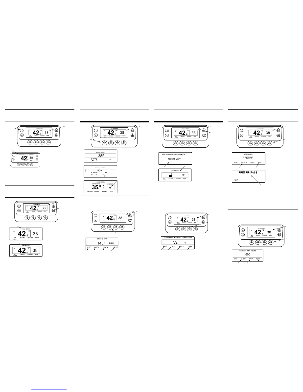
Simple to Start:
1. Press the ON Key.
2. A series of start-up screens will
appear.
3. The Standard Display appears
showing setpoint and box
temperature when the unit is
running.
4. The Standard Display defaults to the “Temperature Watch” screen after
2 1/2 minutes. This screen displays same setpoint and box temperature in
larger font.
NOTE: For more detailed information, see the Operation chapter in
the appropriate unit operating manual.
Simple to Set:
CYCLE-SENTRY or Continuous Run
1. Return to the Standard
Display.
2. Press the MODE
SELECTION Key.
3. The “Programming
Continuous Mode” or
“Programming CYCLESENTRY Mode” screen briefly
appears.
4. The “New System Mode is
Continuous” screen or the
“New System Mode CYCLESENTRY” screen briefly
appears.
5. The Standard Display appears and the heading on top of screen reads
the new mode.
6. Pressing the MODE SELECTION Key again will change the unit back to
the previous mode.
NOTE: For more detailed information, see the Operation chapter in
the appropriate unit operating manual.
3
1
4
1
2 & 6
5
5
Simple to Set:
Setpoint Temperature
1. Return to the Standard
Display.
2. Press the SETPOINT Key
on the Standard Display.
3. Press the + or - Keys to
change the setpoint reading.
4. Press the YES or NO key
accordingly.
5. The Standard Display
appears with setpoint changed
to the new setpoint.
NOTE: For more detailed
information, see the
Operation chapter in the
appropriate unit operating
manual.
Simple to Check:
Gauges
1. Return to the Standard
Display.
2. Press the GAUGES Key.
3. Press BACK or NEXT
Keys to scroll through
following gauges: Coolant
Temperature, Coolant Level,
Engine Oil, Pressure, Amps, Battery Voltage, Engine RPM, Discharge
Pressure, Suction Pressure, ETV Position, I/O. If no keys are pressed
within 30 seconds, the screen will return to the Standard Display.
4. Press the LOCK Key to display any gauge screen for an indefinite
period. Press the key again to unlock the screen.
5. Press the EXIT Key to return to the Standard Display.
NOTE: For more detailed information, see the Operation chapter in
the appropriate unit operating manual.
2
1
4
3
5
1
2
5 4 3 3
Simple to Defrost:
Initiate Manual Defrost
1. Return to the Standard
Display.
2. Press the DEFROST Key.
3. Miscellaneous defrost
programming screens appear.
4. A modified Standard Display
screen appears. The bar
indicator will fill in showing the
time remaining to complete the
Defrost cycle. When the
Defrost cycle is complete the
display returns to Standard
Display screen.
NOTE: For more detailed information, see the Operation chapter in
the appropriate unit operating manual.
Simple to Access:
Sensors
1. Return to the Standard
Display.
2. Press the SENSORS Key.
3. Press the BACK or NEXT
Keys to scroll through the
following sensor screens:
Control Return Air
Temperature,Display Return
Air Temperature, Control Discharge Air Temperature, Display Discharge
Air Temperature, Temperature Differential, Evaporator Coil Temperature,
Ambient Air Temperature, Spare 1 Temperature, Datalogger Temperature
Sensors 1-6 and the Board Temperature Sen so r. If no keys are pressed
within 30 seconds, the screen will return to the Standard Display.
4. Press the LOCK Key to display any sensor screen for an indefinite
period. Press the key again to unlock the screen.
5. Press the EXIT Key to return to the Standard Display.
NOTE: For more detailed information, see the Operation chapter in
the appropriate unit operating manual.
2
1
3
4
2
1
5 4 3 3
Simple to Check:
Pretrip Test
1. Clear all alarm codes.
2. Return to the Standard
Display.
3. Press the MENU key.
4. Press the NEXT Key as
required to show the Pretrip
Menu.
5. Press the SELECT Key to
start a Pretrip Test.
6. If the unit is not running, a Full
Pretrip will be initiated. If the unit
is running in either diesel or
electric mode, a Running Pretrip
will be performed.
7. When all tests are complete, the results are reported a s PASS, CHECK or
FAIL. If the results are CHECK or FAIL, the accompanying alarm codes will
direct the technician to the cause of the problem.
NOTE: For more detailed information, see the Operation chapter in the
appropriate unit operating manual.
Simple to Check:
Hourmeters
1. Return to the Standard Display
screen.
2. Press the MENU Key.
3. Scroll through Main Menu by
repeatedly pressing the NEXT and
BACK Keys until the hourmeters
Main Menu Screen appears.
4. Press the SELECT Key to enter the Hourmeters Menu.
5. Press the NEXT and BACK Keys to view the Hourmeter Displays.
NOTE: For more detailed information, see the Operation chapter in the
appropriate unit operating manual.
3
2
5
4
7
2
1
4 3 & 5 3 & 5
Page 2
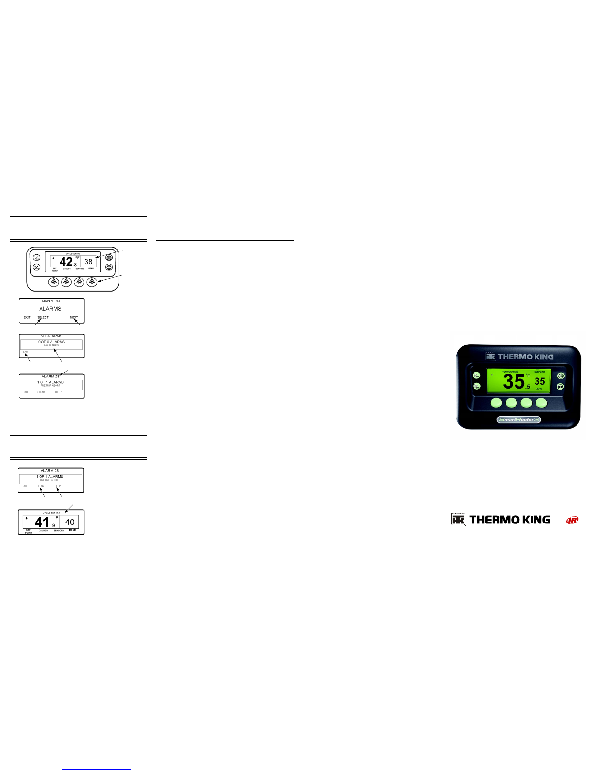
Simple to View:
Cause of Alarm
1. Return to the Standard
Display Screen.
2. Press the MENU Key.
3. Press the NEXT Key until
the Alarm Menu appears.
4. Press the SELECT Key.
The Alarm Display will appear
5. If no alarms are present,
Alarm 00 is shown.
6. Press the EXIT Key to return
to the Standard Display.
7. If alarms are present, the
quantity of alarms and the
most recent alarm code
number will be shown.
8. If there is more than one
alarm, press the NEXT Key to
view each alarm.
9. If a serious alarm occurs,
the unit will be shut down to prevent damage to the unit or the load. If this
occurs, the display will show that the unit is shut down and display the
alarm code that caused the shutdown.
NOTE: For more detailed information, see the Operation chapter in the
appropriate unit operating manual.
Simple to View:
Clearing Alarm Codes
1.Press the CLEAR Key to
clear an alarm.
2. The display screen will
return to the Standard Display
when the alarms are cleared.
3. Press the HELP key for
additional information
regarding the alarm shown on
the display. Also see the
complete Alarm Code list in the
next column.
NOTE: For more detailed
information, see the
Operation chapter in the
appropriate unit operating
manual.
2
1
7
4
3
6
5
1 3
2
Simple to Determine:
Cause of Alarm
0 No Alarms Exist
2 Evaporator Coil Sensor
3 Control Return Air Sensor
4 Control Discharge Air Sensor
5 Ambient Air Sensor
6 Coolant Temp Sensor
7 Engine RPM Sensor
9 High Evaporator Temperature
10 High Discharge Pressure
11 Unit Controlling on Alternate Sensor
12 Sensor or Digital Input Shutdown
13 Sensor Check
15 Check Glow Plugs/Intake Air Heater
17 Engine Failed to Crank
18 High Engine Coolant Temperatu r e
19 Low Engine Oil Pressure
20 Engine Failed to Start
21 Cooling Cycle Check
22 Heating Cycle Check
23 Cooling Cycle Fault
24 Heating Cycle Fault
25 Alternator Check
26 Refrigeration Capacity
28 Pretrip or Self Check Abort
29 Defrost Damper Circuit
30 Defrost Damper Stuck
31 Oil Pressure Switch
32 Refrigeration Capacity Low
33 Check Engine RPM
35 Run Relay Circuit
36 Electric Motor Failed to Run
37 Engine Coolant Level
38 Electric Phase Reversed
39 Water Valve Circuit
40 High Speed Circuit
41 Check Engine Coolant Temperature
42 Unit Forced to Low Speed
43 Unit Forced to Low Speed Modulation
44 Check Fuel System
45 Hot Gas Bypass or Hot Gas Bypass Circuit
46 Check Air Flow
48 Check Belts/Clutch
50 Reset Clock
52 Heat Circuit
54 Test Mode Time-out
61 Low Battery Voltage
62 Ammeter Out of Calibration
63 Engine Stopped
64 Pretrip Reminder
65 Abnormal Temperature Differential
66 Low Engine Oil Level
67 Liquid Line Solenoid Circuit
68 Internal Controller Fault
70 Hourmeter Failure
74 Controller Reset to Defaults
77 Controller EPROM Checksum Failure
79 Internal Data Logger Overflow
80 Compressor Temp Sensor
81 High Compressor Temp
82 High Compressor Temperature Shutdown
83 Low Engine Coolant Temperature
84 Restart Null
85 Forced Unit Operation
86 Discharge Pressure Sensor
87 Suction Pressure Sensor
89 Check Electronic Throttling Valve Circuit
90 Electric Overload
91 Electric Ready Input
92 Sensor Grades Not Set
93 Low Compressor Suction Pressure
94 Loader #1 Circuit
95 Loader #2 Circuit
96 Low Fuel Level
98 Fuel Level Sensor
99 High Compressor Pressure Ratio
108 Door Open Time-out
111 Unit Not Configured Correctly
113 Electric Heat Circuit
114 Multiple Alarms - Cannot Run
117 Auto switch from Diesel to Electric
118 Auto switch from Electric to Diesel
120 Alternator Exciter Circuit
121 Liquid Injection Circuit
122 Diesel/Electric Relay Circuit
127 Setpoint Not Entered
128 Engine Run Time Maintenance Reminder #1
129 Engine Run Time Maintenance Reminder #2
130 Electric Run Time Maintenance Reminder #1
131 Electric Run Time Maintenance Reminder #2
132 Total Unit Run Time Maintenance Reminder #1
133 Total Unit Run Time Maintenance Reminder #2
134 Controller Power On Hours
135 Check Spare Digital Inputs
136 Check Spare Digital Outputs
137 Check Damper Motor Heater Output
141 Autoswitch Diesel to Electric Disabled
145 Loss of Controller "On" Feedback Signal
146 Software Version Mismatch
148 Autoswitch Electric to Diesel Disabled
149 Alarm Not Identified
150 Out of Range Low
151 Out of Range High
157 OptiSet Plus Mismatch
203 Display Return Air Sensor
204 Display Discharge Air Sensor
252 Check Fresh Air Exchange Circuit
SR-3
Smart Reefer 3
Microprocessor
Driver Guide to
Simple
Operation
TK 55072-2-PC (Rev. 0, 04/11) ©Thermo King Corporation
 Loading...