

Page 1

Operator’s Manual
SB-210+/SB-310+
Operator’s Manual
SB-210+/SB-310+
TK 53942-2-OP (Rev. 1, 11/09)
Page 2

Copyright© 2009 Thermo King Corp., Minneapolis, MN, USA
Printed in USA
SB-210+/SB-310+
TK 53942-2-OP (Rev. 1, 11/09)
Copyright© 2009 Thermo King Corp., Minneapolis, MN, USA
Printed in USA
SB-210+/SB-310+
TK 53942-2-OP (Rev. 1, 11/09)
Page 3

Disclaimer
This manual is published for informational purposes only. Thermo King Corporation makes no
representations or warranties, express or implied, with respect to the information, recommendations and
descriptions contained in this manual and such information, recommendations and descriptions should
not be regarded as all-inclusive or covering all contingencies. If you have questions or require further
information, please contact your local Thermo King dealer.
The procedures described herein should be undertaken only by qualified personnel. Failure to implement
these procedures correctly may cause damage to the Thermo King unit or other property or personal
injury.
Thermo King Corporation and its affiliates shall have no liability in contract or tort (including negligence
and/or strict liability) or otherwise, to any person or entity for any personal injury, property damage or any
other direct, indirect, special or consequential damage or liability whatsoever, arising out of or resulting
from any actions by any person that are contrary to this manual or any of the information,
recommendations or descriptions contained herein or the failure of any person to implement the
procedures described herein correctly or to follow caution and safety decals located on the Thermo King
unit.
Page 4

3
Table of Contents
Table of Contents . . . . . . . . . . . . . . . . . . . . . . . . . . . . 3
List of Figures . . . . . . . . . . . . . . . . . . . . . . . . . . . . . . . 7
Introduction . . . . . . . . . . . . . . . . . . . . . . . . . . . . . . . . 11
Safety Precautions . . . . . . . . . . . . . . . . . . . . . . . . . . 13
General Safety Practices . . . . . . . . . . . . . . . . . . . . . . 13
Automatic Start/Stop Operation . . . . . . . . . . . . . . . . . 14
Electrical Hazard . . . . . . . . . . . . . . . . . . . . . . . . . . . . . 14
Refrigerant . . . . . . . . . . . . . . . . . . . . . . . . . . . . . . . . . 14
Refrigerant Oil . . . . . . . . . . . . . . . . . . . . . . . . . . . . . . . 15
First Aid . . . . . . . . . . . . . . . . . . . . . . . . . . . . . . . . . . . . 15
First Aid–Refrigerant . . . . . . . . . . . . . . . . . . . . . . . 15
First Aid–Refrigerant Oil . . . . . . . . . . . . . . . . . . . . 15
Safety Decals and Locations . . . . . . . . . . . . . . . . . . . 16
EPA Emission Control System Warranty
Statement . . . . . . . . . . . . . . . . . . . . . . . . . . . . . . . . . . 19
Responsibilities . . . . . . . . . . . . . . . . . . . . . . . . . . . . . . 20
Thermo King Corporation Responsibilities . . . . . .20
Owner Responsibilities . . . . . . . . . . . . . . . . . . . . .21
Limitations . . . . . . . . . . . . . . . . . . . . . . . . . . . . . . . . . .21
Unit Description . . . . . . . . . . . . . . . . . . . . . . . . . . . . .23
Unit Overview . . . . . . . . . . . . . . . . . . . . . . . . . . . . . . . .23
Design Features . . . . . . . . . . . . . . . . . . . . . . . . . . . . . .24
Diesel Engine . . . . . . . . . . . . . . . . . . . . . . . . . . . . . . . .26
ELC (Extended Life Coolant) . . . . . . . . . . . . . . . . . . . .27
EMI 3000 . . . . . . . . . . . . . . . . . . . . . . . . . . . . . . . . . . .27
Thermo King X430L Reciprocating Compressor . . . . .28
Electronic Throttling Valve . . . . . . . . . . . . . . . . . . . . . .28
SMART REEFER 2 (SR-2) Control System . . . . . . . . .29
CYCLE-SENTRY Operation . . . . . . . . . . . . . . . . .29
Continuous Run Operation . . . . . . . . . . . . . . . . . .29
CYCLE-SENTRY Start-Stop Controls . . . . . . . . . .30
Data Logging . . . . . . . . . . . . . . . . . . . . . . . . . . . . .31
OptiSet Plus . . . . . . . . . . . . . . . . . . . . . . . . . . . . .32
FreshSet . . . . . . . . . . . . . . . . . . . . . . . . . . . . . . . .32
Defrost . . . . . . . . . . . . . . . . . . . . . . . . . . . . . . . . . .32
Page 5

Table of Contents
4
Opening the Front Doors . . . . . . . . . . . . . . . . . . . . . . .34
Opening the Secondary Door Latch . . . . . . . . . . .34
Closing the Front Doors . . . . . . . . . . . . . . . . . . . . . . . . 35
Engine Compartment Components . . . . . . . . . . . . . . .36
Unit Protection Devices . . . . . . . . . . . . . . . . . . . . . . . .37
Remote Status Display (Optional) . . . . . . . . . . . . . . 41
Manual Pretrip Inspection
(Before Starting the Unit) . . . . . . . . . . . . . . . . . . . . . 45
Operating Instructions . . . . . . . . . . . . . . . . . . . . . . . 47
SMART REEFER 2 (SR-2) Controller Overview . . . . .47
HMI Control Panel . . . . . . . . . . . . . . . . . . . . . . . . . . . .49
Control Panel Display . . . . . . . . . . . . . . . . . . . . . . 49
Control Panel Keys . . . . . . . . . . . . . . . . . . . . . . . . 50
Turning Unit On . . . . . . . . . . . . . . . . . . . . . . . . . . . . . .51
Turning Unit Off . . . . . . . . . . . . . . . . . . . . . . . . . . . . . .53
Standard Display . . . . . . . . . . . . . . . . . . . . . . . . . . . . .54
Standard Display Variations . . . . . . . . . . . . . . . . . . . . 55
Temperature Watch Display . . . . . . . . . . . . . . . . . . . .56
Alarm Display . . . . . . . . . . . . . . . . . . . . . . . . . . . . . . . 57
Starting the Diesel Engine . . . . . . . . . . . . . . . . . . . . . .58
Unit Fails To Start . . . . . . . . . . . . . . . . . . . . . . . . .58
After Start Inspection . . . . . . . . . . . . . . . . . . . . . . 59
Electric Standby Operation . . . . . . . . . . . . . . . . . . . . . 60
Starting the Unit on Electric Standby Operation . 61
Unit Fails to Start . . . . . . . . . . . . . . . . . . . . . . . . . 62
Switching from Diesel to Electric . . . . . . . . . . . . . 63
Switching from Electric to Diesel . . . . . . . . . . . . . 64
Changing the Setpoint . . . . . . . . . . . . . . . . . . . . . . . . 65
Selection of Operating Modes . . . . . . . . . . . . . . . . . . 68
Selecting CYCLE-SENTRY or Continuous Mode . . . 69
Initiating a Manual Defrost Cycle . . . . . . . . . . . . . . . . 71
Terminating a Defrost Cycle . . . . . . . . . . . . . . . . . . . . 72
Viewing Gauge Readings . . . . . . . . . . . . . . . . . . . . . . 73
Viewing Sensor Readings . . . . . . . . . . . . . . . . . . . . . 75
Navigating the Main Menu . . . . . . . . . . . . . . . . . . . . . 79
Main Menu Choices . . . . . . . . . . . . . . . . . . . . . . . 80
Language Menu . . . . . . . . . . . . . . . . . . . . . . . . . . . . . 82
Alarms Menu . . . . . . . . . . . . . . . . . . . . . . . . . . . . . . . 85
Important Alarm Notes . . . . . . . . . . . . . . . . . . . . . 86
Datalogger Menu . . . . . . . . . . . . . . . . . . . . . . . . . . . . 88
Initiating a Start of Trip . . . . . . . . . . . . . . . . . . . . . 88
Printing a Trip Report . . . . . . . . . . . . . . . . . . . . . . 90
Hourmeters Menu . . . . . . . . . . . . . . . . . . . . . . . . . . . . 93
Mode Menu . . . . . . . . . . . . . . . . . . . . . . . . . . . . . . . . 96
Turning CYCLE-SENTRY On or Off . . . . . . . . . . 97
Page 6

Table of Contents
5
Selecting Keypad Lockout . . . . . . . . . . . . . . . . . . 99
Selecting Sleep Mode . . . . . . . . . . . . . . . . . . . . . 101
Pretrip Tests . . . . . . . . . . . . . . . . . . . . . . . . . . . . . . . 104
Initiating a Pretrip Test . . . . . . . . . . . . . . . . . . . . 106
Stopping a Pretrip Test . . . . . . . . . . . . . . . . . . . . 107
Electric Standby/Diesel Mode . . . . . . . . . . . . . . . . . . 109
Adjust Brightness Menu . . . . . . . . . . . . . . . . . . . . . . 111
Time Display . . . . . . . . . . . . . . . . . . . . . . . . . . . . . . . 114
OptiSet Plus . . . . . . . . . . . . . . . . . . . . . . . . . . . . . . . 115
Selecting a Named Product . . . . . . . . . . . . . . . . 117
Changing the Setpoint for a Named Product . . . 122
Selecting a Setpoint . . . . . . . . . . . . . . . . . . . . . . 125
Optional Rear Remote Control Panel . . . . . . . . . . 129
Rear Remote Control Panel Functions . . . . . . . . . . . 130
Run . . . . . . . . . . . . . . . . . . . . . . . . . . . . . . . . . . . 130
Stand By . . . . . . . . . . . . . . . . . . . . . . . . . . . . . . . 131
Keypad . . . . . . . . . . . . . . . . . . . . . . . . . . . . . . . . . . . 133
Display . . . . . . . . . . . . . . . . . . . . . . . . . . . . . . . . . . . 134
Reading a Typical Remote Standard Display . . . . . . 135
Remote Control Panel Lockout . . . . . . . . . . . . . . . . . 135
Turning the Unit On or Off (Configured for STAND BY
Operation) . . . . . . . . . . . . . . . . . . . . . . . . . . . . . . 136
Turning the Unit On and Off (Configured for RUN
Operation) . . . . . . . . . . . . . . . . . . . . . . . . . . . . . .136
Changing the Setpoint . . . . . . . . . . . . . . . . . . . . . . . .137
Selecting Cycle-Sentry or Continuous Mode . . . . . . .138
Displaying the Discharge Air Temperature . . . . . . . .139
Viewing and Clearing Alarm Codes . . . . . . . . . . . . . .140
Starting a Manual Defrost Cycle . . . . . . . . . . . . . . . .141
Sending a Start of Trip Marker . . . . . . . . . . . . . . . . . .142
Running a Pretrip Test . . . . . . . . . . . . . . . . . . . . . . . .143
Alarm Codes . . . . . . . . . . . . . . . . . . . . . . . . . . . . . . .145
Introduction . . . . . . . . . . . . . . . . . . . . . . . . . . . . . . . .145
Alarm Types . . . . . . . . . . . . . . . . . . . . . . . . . . . . . . . .145
Corrective Action . . . . . . . . . . . . . . . . . . . . . . . . . . . .148
Loading and Enroute Inspections . . . . . . . . . . . . .165
Pre-Loading Inspection . . . . . . . . . . . . . . . . . . . . . . .165
Post-Loading Inspection . . . . . . . . . . . . . . . . . . . . . .167
Enroute Inspections . . . . . . . . . . . . . . . . . . . . . . .168
Jump Starting . . . . . . . . . . . . . . . . . . . . . . . . . . . . . .171
Specifications . . . . . . . . . . . . . . . . . . . . . . . . . . . . . .175
Engine . . . . . . . . . . . . . . . . . . . . . . . . . . . . . . . . . . . .175
Belt Tension . . . . . . . . . . . . . . . . . . . . . . . . . . . . . . . .178
Page 7

Table of Contents
6
Electrical Control System . . . . . . . . . . . . . . . . . . . . . 179
Electric Standby (Model 50 Units Only) . . . . . . . . . . .180
Electric Fuel Heater (Optional) . . . . . . . . . . . . . . . . . 181
Refrigeration System . . . . . . . . . . . . . . . . . . . . . . . . .182
Maintenance Inspection Schedule . . . . . . . . . . . . . 183
Warranty . . . . . . . . . . . . . . . . . . . . . . . . . . . . . . . . . . 189
Glossary . . . . . . . . . . . . . . . . . . . . . . . . . . . . . . . . . . 191
Index . . . . . . . . . . . . . . . . . . . . . . . . . . . . . . . . . . . . . 197
Serial Number Locations . . . . . . . . . . . . . . . . . . . . 201
Emergency Cold Line . . . . . . . . . . . . . . . . . . . . . . . 205
Recover Refrigerant . . . . . . . . . . . . . . . . . . . . . . . . 206
CALIFORNIA
Proposition 65 Warning . . . . . . . . . . . . . . . . . . . . . 207
Page 8

7
List of Figures
Figure 1:ELC (Extended Life Coolant) Nameplate
(Located on expansion tank in units
equipped with ELC) . . . . . . . . . . . . . . . . . . . . . . . 16
Figure 2:Belt Warning
(Located on condenser housing) . . . . . . . . . . . . . 16
Figure 3:Belt Replacement Caution
(Located on condenser housing) . . . . . . . . . . . . . 16
Figure 4:Automatic Start Caution
(Locations vary depending on model. Decals are
located near areas that contain moving parts which
can cause severe injuries if hands or clothing become
tangled when unit automatically starts.) . . . . . . . . 17
Figure 5:Fan Caution
(Locations vary depending on model. Decals are
located near areas that contain fans which can ca use
severe injuries when unit automatically starts.) . . 17
Figure 6:Door Latch Warning
(Located on curbside door) . . . . . . . . . . . . . . . . . . 18
Figure 7:Front View . . . . . . . . . . . . . . . . . . . . . . . . . . . 23
Figure 8:TK486V (TK486VH is Similar) Tier 2 . . . . . . 26
Figure 9:Compressors . . . . . . . . . . . . . . . . . . . . . . . . 28
Figure 10:HMI Controller and Data Ports . . . . . . . . . . .31
Figure 11:Door Latch Location . . . . . . . . . . . . . . . . . . .34
Figure 12:Opening Secondary Door Latch . . . . . . . . .34
Figure 13:Engine Compartment . . . . . . . . . . . . . . . . . .36
Figure 14:Control Box With Service Door Open . . . . .39
Figure 15:Control Box With Control Box Door Open . .40
Figure 16:Interface Board . . . . . . . . . . . . . . . . . . . . . .40
Figure 17:Remote Status Display (All LEDs Shown) . .41
Figure 18:Normal Operation No Alarms . . . . . . . . . . . .41
Figure 19:Check Alarm . . . . . . . . . . . . . . . . . . . . . . . .42
Figure 20:Shutdown Alarm . . . . . . . . . . . . . . . . . . . . .42
Figure 21:Remote Status Display with Fuel Level . . . .43
Figure 22:Remote Status Display
with Fuel Level and Temperature . . . . . . . . . . . . .43
Figure 23:SR-2 HMI Control Panel . . . . . . . . . . . . . . .47
Figure 24:Control Box With Service Door Open . . . . .48
Figure 25:Control Panel Display and Keys . . . . . . . . .49
Figure 26:Press On Key . . . . . . . . . . . . . . . . . . . . . . . .51
Figure 27:Turning Unit On Screen Sequence . . . . . . .52
Figure 28:Press Off Key . . . . . . . . . . . . . . . . . . . . . . . .53
Figure 29:Turning Unit Off Screen Sequence . . . . . . .53
Page 9

List of Figures
8
Figure 30:Standard Display . . . . . . . . . . . . . . . . . . . . .54
Figure 31: Standard Display Variations . . . . . . . . . . . .55
Figure 32:Temperature Watch Display . . . . . . . . . . . . 56
Figure 33:Alarm Display . . . . . . . . . . . . . . . . . . . . . . . 57
Figure 34:Electric Power Receptacle . . . . . . . . . . . . . 60
Figure 35:Electric Standby Detected Screen . . . . . . . .61
Figure 36:Electric Motor Starting Screen . . . . . . . . . . . 62
Figure 37:Electric Standby Detected Screen . . . . . . . .63
Figure 38:Programming Electric Standby Screen . . . .63
Figure 39:Electric Standby Undetected Screen . . . . . .64
Figure 40:Programming Diesel Mode Screen . . . . . . .64
Figure 41:Changing Setpoint . . . . . . . . . . . . . . . . . . . . 65
Figure 42:Changing the Setpoint Screen Sequence . .67
Figure 43:Changing Mode . . . . . . . . . . . . . . . . . . . . . .69
Figure 44:Screen Sequence for Changing from
CYCLE-SENTRY Mode to Continuous Mode . . . .70
Figure 45:Screen Sequence for Changing from
Continuous Mode to CYCLE-SENTRY Mode . . . .70
Figure 46:Initiating a Manual Defrost Cycle . . . . . . . . . 71
Figure 47:Initiating Manual Defrost Screen Sequence 72
Figure 48:Viewing Gauges . . . . . . . . . . . . . . . . . . . . . 73
Figure 49:Viewing Gauges Screen Sequence . . . . . . .74
Figure 50:Viewing Sensors . . . . . . . . . . . . . . . . . . . . . 75
Figure 51:Viewing Sensors Screen Sequence (continued
on next page) . . . . . . . . . . . . . . . . . . . . . . . . . . . . 77
Figure 52:Viewing Sensors Screen Sequence (continued
from previous page) . . . . . . . . . . . . . . . . . . . . . . . 78
Figure 53:Accessing Main Menu . . . . . . . . . . . . . . . . 79
Figure 54:Main Menu Choices . . . . . . . . . . . . . . . . . . 80
Figure 55:Standard Display . . . . . . . . . . . . . . . . . . . . 82
Figure 56:Standard Display . . . . . . . . . . . . . . . . . . . . 83
Figure 57:Change Language Screen Sequence . . . . 84
Figure 58:Standard Display . . . . . . . . . . . . . . . . . . . . 85
Figure 59:Viewing and Clearing Alarms Screen Sequence
87
Figure 60:Standard Display . . . . . . . . . . . . . . . . . . . . 88
Figure 61:Start of Trip Screen Sequence . . . . . . . . . . 89
Figure 62:Printer Port Location . . . . . . . . . . . . . . . . . 90
Figure 63:Standard Display . . . . . . . . . . . . . . . . . . . . 91
Figure 64:Print Report Screen Sequence . . . . . . . . . 92
Figure 65:Standard Display . . . . . . . . . . . . . . . . . . . . 93
Figure 66:Viewing Hourmeters Screen Sequence
(continued on next page) . . . . . . . . . . . . . . . . . . . 94
Figure 67:Viewing Hourmeters Screen Sequence
(continued from previous page) . . . . . . . . . . . . . . 95
Figure 68:Standard Display . . . . . . . . . . . . . . . . . . . . 97
Figure 69:Selecting Mode Screen Sequence . . . . . . . 98
Figure 70:Standard Display . . . . . . . . . . . . . . . . . . . . 99
Page 10

List of Figures
9
Figure 71:Mode Menu Display . . . . . . . . . . . . . . . . . . 99
Figure 72:Keypad Lockout Display . . . . . . . . . . . . . . 100
Figure 73:Standard Display . . . . . . . . . . . . . . . . . . . 101
Figure 74:Selecting Sleep Mode Screen Sequence . 103
Figure 75:Standard Display . . . . . . . . . . . . . . . . . . . 106
Figure 76:No Pretrip Alarm Active Display . . . . . . . . 106
Figure 77:Pretrip Test Screen Sequence . . . . . . . . . 108
Figure 78:Standard Display . . . . . . . . . . . . . . . . . . . 109
Figure 79:Programming Diesel Mode . . . . . . . . . . . . 110
Figure 80:Programming Electric Standby Mode . . . . 111
Figure 81:Standard Display . . . . . . . . . . . . . . . . . . . 112
Figure 82:Adjusting Display Brightness Screen Sequence
113
Figure 83:Time and Date Screens . . . . . . . . . . . . . . 114
Figure 84:Standard Display with Product Soft Key . . 115
Figure 85:Standard Display with
Product/Setpoint Soft Key . . . . . . . . . . . . . . . . . 116
Figure 86:Selecting Named Product . . . . . . . . . . . . . 117
Figure 87:Selecting or Changing Named Product Screen
Sequence . . . . . . . . . . . . . . . . . . . . . . . . . . . . . . 119
Figure 88:Selecting Setpoint for Named Product Screen
Sequence . . . . . . . . . . . . . . . . . . . . . . . . . . . . . . 121
Figure 89:Changing Setpoint for Named Product . . . 122
Figure 90:Changing Setpoint for Named Product Screen
Sequence . . . . . . . . . . . . . . . . . . . . . . . . . . . . . .124
Figure 91:Selecting or Changing Setpoint . . . . . . . . .125
Figure 92:Selecting or Changing Numeric Setpoint
Screen Sequence . . . . . . . . . . . . . . . . . . . . . . . .127
Figure 93:Rear Remote Control Panel . . . . . . . . . . . .129
Figure 94:Rear Remote Control Panel Display . . . . .131
Figure 95:Unit HMI Control Panel Display . . . . . . . . .131
Figure 96:Press Select Key . . . . . . . . . . . . . . . . . . . .132
Figure 97:Rear Remote Control Panel . . . . . . . . . . . .133
Figure 98:Rear Remote Control Panel . . . . . . . . . . . .134
Figure 99:Remote Standard Display . . . . . . . . . . . . .135
Figure 100:Remote Lock Out Display . . . . . . . . . . . .135
Figure 101:Stand By Display . . . . . . . . . . . . . . . . . . .136
Figure 102:Standard Display . . . . . . . . . . . . . . . . . . .136
Figure 103:Press Up or Down Arrow Keys . . . . . . . .137
Figure 104:Press Enter Key . . . . . . . . . . . . . . . . . . . .137
Figure 105:Press Select Key . . . . . . . . . . . . . . . . . . .138
Figure 106:Press Up or Down Arrow Keys . . . . . . . .138
Figure 107:Press Enter Key . . . . . . . . . . . . . . . . . . . .138
Figure 108:Press Select Key Twice . . . . . . . . . . . . . .139
Figure 109:Press Select Key Three Times . . . . . . . .140
Figure 110:Press Enter Key . . . . . . . . . . . . . . . . . . . .140
Figure 111:No Alarms Display . . . . . . . . . . . . . . . . . .140
Figure 112:Press Defrost Key . . . . . . . . . . . . . . . . . .141
Page 11

List of Figures
10
Figure 113:Press Enter Key . . . . . . . . . . . . . . . . . . . 141
Figure 114:Defrost Icon Displayed . . . . . . . . . . . . . . 141
Figure 115:Press TK Logo Key . . . . . . . . . . . . . . . . . 142
Figure 116:Press Enter Key . . . . . . . . . . . . . . . . . . . 142
Figure 117:Press Pretrip Key . . . . . . . . . . . . . . . . . . 143
Figure 118:Press Enter Key . . . . . . . . . . . . . . . . . . . 143
Figure 119:Pretrip Display . . . . . . . . . . . . . . . . . . . . . 144
Figure 120:Pass Pretrip Display . . . . . . . . . . . . . . . .144
Figure 121:Log Alarms Screen . . . . . . . . . . . . . . . . . 145
Figure 122:Alarm Display . . . . . . . . . . . . . . . . . . . . . 146
Figure 123:Shutdown Alarm Display . . . . . . . . . . . . . 147
Figure 124:Loading Considerations . . . . . . . . . . . . . . 166
Figure 125:Unit Battery . . . . . . . . . . . . . . . . . . . . . . . 172
Figure 126:Sequence for Connecting Jumper Cables . . .
172
Figure 127:Unit Engine . . . . . . . . . . . . . . . . . . . . . . .173
Figure 128:Sequence for Disconnecting Jumper Cables
174
Figure 129:Compressor Serial Number Location . . . 202
Figure 130:Engine Serial Number Location . . . . . . . . 202
Figure 131:Unit Serial Number Plate Locations
(on the bulkhead above compressor inside
curbside door and on roadside of evaporator) . .203
Figure 132:Unit Serial Number Plate . . . . . . . . . . . . .203
Page 12

11
Introduction
There is nothing complicated about operating and maintaining
your Thermo King unit, but a few minutes studying this
manual will be time well spent.
Performing pre-trip checks and enroute inspections on a
regular basis will minimize on-the-road operating problems . A
regular maintenance program will also help to keep your unit
in top operating condition. If factory recommended procedures
are followed, you will find that you have purchased the most
efficient and dependable temperature control system available.
All service requirements, major and minor, should be handled
by a Thermo King dealer for four very important reasons:
• They are equipped with the factory recommended tools to
perform all service functions
• They have factory trained and certified technicians
• They have genuine Thermo King replacement parts
• The warranty on your new unit is valid only when the
repair and replacement of component parts is performed
by an authorized Thermo King dealer.
IMPORTANT: This manual is published for informational
purposes only and the information furnished herein should
not be considered as all-inclusive or meant to cover all
contingencies. If more information is required, consult your
Thermo King Service Directory for the location and
telephone number of the local dealer.
Page 13

Introduction
12
Introduction
12
Page 14

13
Safety Precautions
Thermo King recommends that servicing be done only by a
Thermo King dealer. However , you should be aware of several
safety practices. This chapter gives basic safety precautions for
working with Thermo King units and describes the safety
stickers on your unit that you should be familiar with.
General Safety Practices
DANGER: NEVER operate the unit with the
compressor discharge valve closed. Doing so could
cause the compressor to explode, causing death or
serious injury.
WARNING: Always wear goggles or safety glasses
when working with or around the refrigeration system
or battery. Refrigerant or battery acid can cause
permanent damage if it comes in contact with your
eyes.
WARNING: Keep hands and loose clothing clear of
fans and belts at all times when the unit is operating
or when opening or closing compressor service
valves.
WARNING: Exposed coil fins can cause painful
lacerations. Service work on the evaporator or
condenser coils should be done by a certified Thermo
King technician.
WARNING: Do not apply heat to a closed cooling
system. Before applying heat to a cooling system,
drain it. Then flush it with water and drain the water.
Antifreeze contains water and ethylene glycol. The
ethylene glycol is flammable and can ignite if the
antifreeze is heated enough to boil off the water.
Page 15

Safety Precautions
14
Automatic Start/Stop Operation
This unit is capable of automatic operation and could start at
any time without warning.
Electrical Hazard
Refrigerant
Although fluorocarbon refrigerants are classified as safe, use
caution when working with refrigerants or in areas where they
are being used.
CAUTION: Use extreme caution when drilling holes
in the unit. Drilling into electrical wiring or
refrigerant lines could cause a fire. Do not drill into
structural components.
WARNING: The unit can start at any time without
warning. Press the O
FF
key on the HMI control panel
and place the microprocessor On/Off switch in the
Off position before inspecting or servicing any part of
the unit.
CAUTION: Turn off the high voltage power supply
and disconnect the electric cable before working on
the unit. Units with electric standby present a
potential electrical hazard.
DANGER: Fluorocarbon refrigerants can produce
toxic gases. In the presence of an open flame or
electrical short, these gases are severe respiratory
irritants CAPABLE OF CAUSING DEATH.
DANGER: Fluorocarbon refrigerants tend to
displace air and can cause oxygen depletion which
could result in DEA TH BY SUFFOCA TION. Provide
adequate ventilation in enclosed or confined areas.
WARNING: Fluorocarbon refrigerants evaporate
rapidly, freezing anything they contact if accidentally
released into the atmosphere from the liquid state.
Page 16

Safety Precautions
15
Refrigerant Oil
Observe the following precautions when working with or
around refrigerant oil:
First Aid
First Aid–Refrigerant
Eyes: For contact with liquid, immediately flush eyes with
large amounts of water. Get prompt medical attention.
Skin: Flush areas with large amounts of warm water. Do not
apply heat. Wrap burns with dry, sterile, bulky dressing to
protect from infection or injury. Get prompt medical attention.
Inhalation: Move victim to fresh air and restore breathing if
necessary. Stay with victim until emergency personnel arrive.
First Aid–Refrigerant Oil
Eyes: Immediately flush eyes with large amounts of water for
at least 15 minutes while holding the eyelids open. Get prompt
medical attention.
Skin: Remove contaminated clothing. Wash thoroughly with
soap and water. Get medical attention if irritation persists.
Inhalation: Move victim to fresh air and restore breathing if
necessary. Stay with victim until emergency personnel arrive.
Ingestion: Do not induce vomiting. Immediately contact
local poison control center or physician.
WARNING: Always wear goggles or safety glasses to
protect eyes from refrigerant oil contact.
WARNING: Protect skin and clothing from
prolonged or repeated contact with refrigerant oil.
Rubber gloves are recommended.
WARNING: W ash thoroughly immediately after
handling refrigerant oil to prevent irritation.
Page 17

Safety Precautions
16
Safety Decals and Locations
Figure 1: ELC (Extended Life Coolant) Nameplate
(Located on expansion tank in units
equipped with ELC)
Figure 2: Belt Warning
(Located on condenser housing)
Figure 3: Belt Replacement Caution
(Located on condenser housing)
AJA1947
AKB65
AKB66
Safety Precautions
16
Safety Decals and Locations
Figure 1: ELC (Extended Life Coolant) Nameplate
(Located on expansion tank in units
equipped with ELC)
Figure 2: Belt Warning
(Located on condenser housing)
Figure 3: Belt Replacement Caution
(Located on condenser housing)
AJA1947
AKB65
AKB66
Page 18
Safety Precautions
17
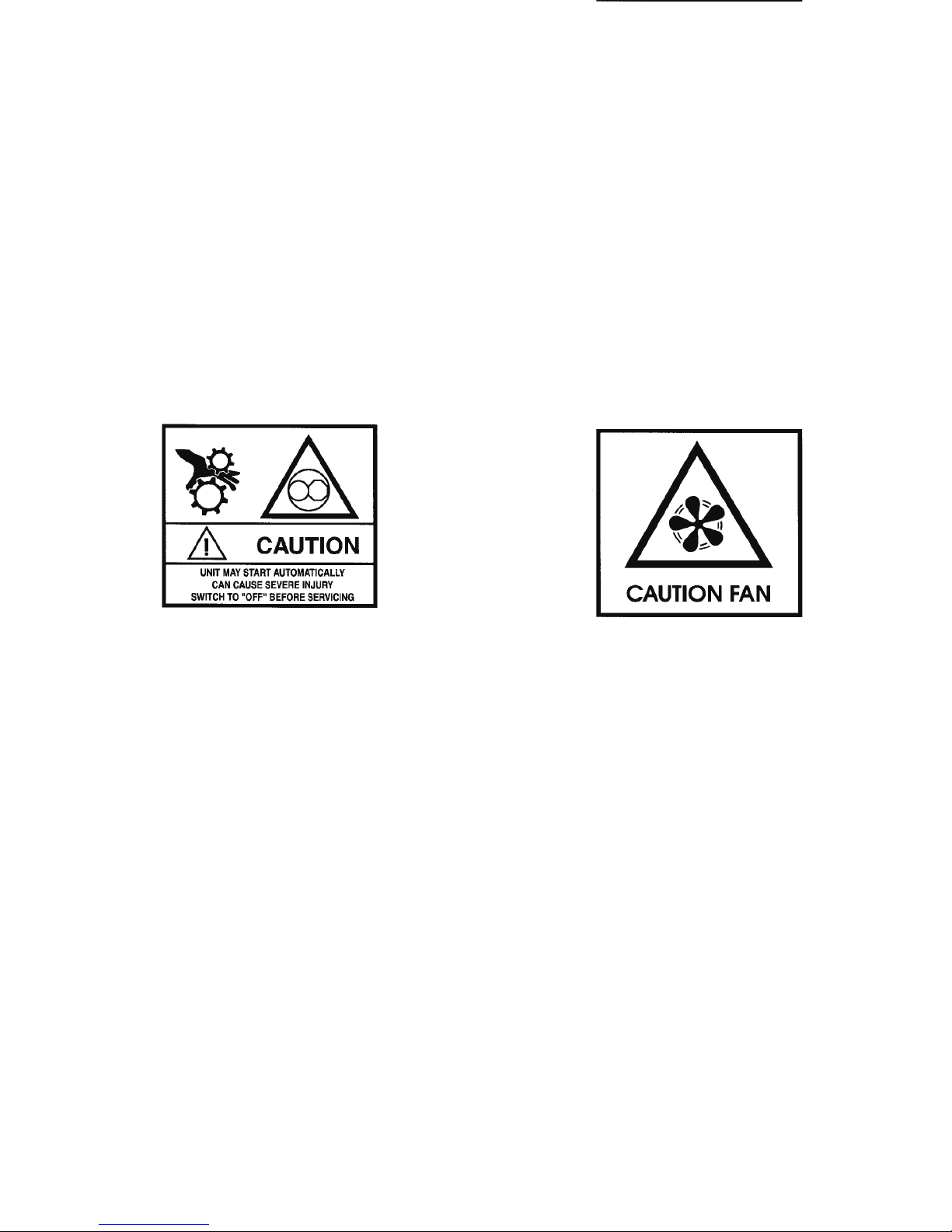
Figure 4: Automatic Start Caution
(Locations vary depending on model. Decals are
located near areas that contain moving parts which
can cause severe injuries if hands or clothing become
tangled when unit automatically starts.)
Figure 5: Fan Caution
(Locations vary depending on model. Decals are
located near areas that contain f ans which can cause
severe injuries when unit automatically starts.)
AKB67 AKB68
Safety Precautions
17
Figure 4: Automatic Start Caution
(Locations vary depending on model. Decals are
located near areas that contain moving parts which
can cause severe injuries if hands or clothing become
tangled when unit automatically starts.)
Figure 5: Fan Caution
(Locations vary depending on model. Decals are
located near areas that contain f ans which can cause
severe injuries when unit automatically starts.)
AKB67 AKB68
Page 19
Safety Precautions
18
Figure 6: Door Latch Warning
(Located on curbside door)
WARNING
ATENCIÓN
NEW DOOR LATCH DESIGN
REQUIRES DOOR TO BE SLAMMED
SHUT BEFORE MOVING TRAILER.
FAILURE TO CLOSE DOOR FIRMLY
CAN ALLOW WIND TO TEAR DOOR
FROM REFRIGERATION UNIT AND
CAUSE INJURY TO OTHERS.
NUEVO DESEÑO DE CERRADURA
REQUIERE ASOTAR LA PUERTA ANTES
DE CONDUCIR EL TRAILER.
AL NO CERRAR LA PUERTA CON
FIRMEZA EL VIENTO PODRÍA
DESPRENDER LA PUERTA DE LA
UNIDAD DE REFRIGERACIÓN Y
CAUSAR DAÑOS A OTROS.
AEA2422
Page 20

19
EPA Emission Control System Warranty
Statement
Thermo King warrants to the initial owner and each subsequent
owner that the certified, non-road diesel engine in your unit is:
1. Designed, built and equipped so as to conform, at the time
of sale, with all applicable regulations adopted by the
United States Environmental Protection Agency (EPA).
2. Free from defects in materials and workmanship in
specific emission related parts for a period of five years or
3,000 hours of operation, whichever comes first, after date
of delivery to the initial owner.
If an emission-related part or component fails during the
warranty period, it will be repaired or replaced. Any such part
or component repaired or replaced under warranty is warranted
for the warranty period.
During the term of this warranty, Thermo King will provide,
through a Thermo King authorized service dealer or other
establishment authorized by Thermo King, repair or
replacement of any warranted part at no charge to the non-road
engine owner.
In emergency, repairs may be performed at any service
establishment, or by the owner, using any replacement part.
Thermo King will reimburse the owner for their expenses,
including diagnostic charges for such emergency repair. These
expenses shall not exceed Thermo King’ s suggested retail price
for all warranted parts replaced, and labor changes based on
Thermo King’s recommended time allowance for the warranty
repair and the geographically appropriate hourly labor rate.
Page 21

EPA Emission Control System Warranty Statement
20
Any replacement part can be used for maintenance or repairs.
The owner should ensure that such parts are equivalent in
design and durability to genuine Thermo King parts. However,
Thermo King is not liable for parts that are not genuine
Thermo King parts.
A part not being available within 30 days or repair not being
completed within 30 days constitutes an emergency.
As a condition of reimbursement, replaced parts and received
invoices must be presented at a place of business of a Thermo
King authorized service dealer or other establishment
authorized by Thermo King.
This warranty covers the following emission-related parts and
components:
• Fuel Injection System
• Intake Manifold
• Exhaust Manifold
• Miscellaneous hoses, clamps, connectors and sealing
devices used in the above systems.
If failure of one of these parts or components results in failure
of another part or component, both will be covered by this
warranty.
Responsibilities
This warranty is subject to the following:
Thermo King Corporation
Responsibilities
During the emission warranty period, if a defect in material or
workmanship of a warranted part or component is found,
Thermo King will provide:
• New, remanufactured, or repaired parts or components
required to correct the defect.
NOTE: Items replaced under this warranty become the
property of Thermo King.
• Labor, during normal working hours, required to make the
warranty repair. This includes diagnosis and labor to
remove and install the engine, if necessary.
Page 22

EPA Emission Control System Warranty Statement
21
Owner Responsibilities
During the emission warranty period, the owner is responsible
for:
• The performance of all required maintenance. A warranty
claim will not be denied because the scheduled
maintenance was not performed. However, if the lack of
required maintenance was the reason for the repair, then
the claim will be denied.
• Premium of overtime cost.
• Cost to investigate complaints that are not caused by
defects in Thermo King material or workmanship.
• Providing timely notice of a warrantable failure and
promptly making the product available for repair.
Limitations
Thermo King is not responsible for resultant damages to an
emission-related part or component resulting from:
• Any application or installation Thermo King deems
improper as explained in this Operator’s Manual, or any
other manuals provided for the unit.
• Attachments, accessory items, or parts not authorized for
use by Thermo King.
• Improper off-road engine maintenance, repair or abuse.
• Owner’s unreasonable delay in making the product
available after being notified of a potential product
problem.
This warranty is in addition to Thermo King’s standard
warranty applicable to the off-road engine product involved.
Remedies under this warranty are limited to the provision of
material and services as specified herein. Thermo King is not
responsible for incidental or consequential damages such as
downtime or loss of engine powered equipment.
Page 23

EPA Emission Control System Warranty Statement
22
EPA Emission Control System Warranty Statement
22
Page 24
23
Unit Description
Unit Overview
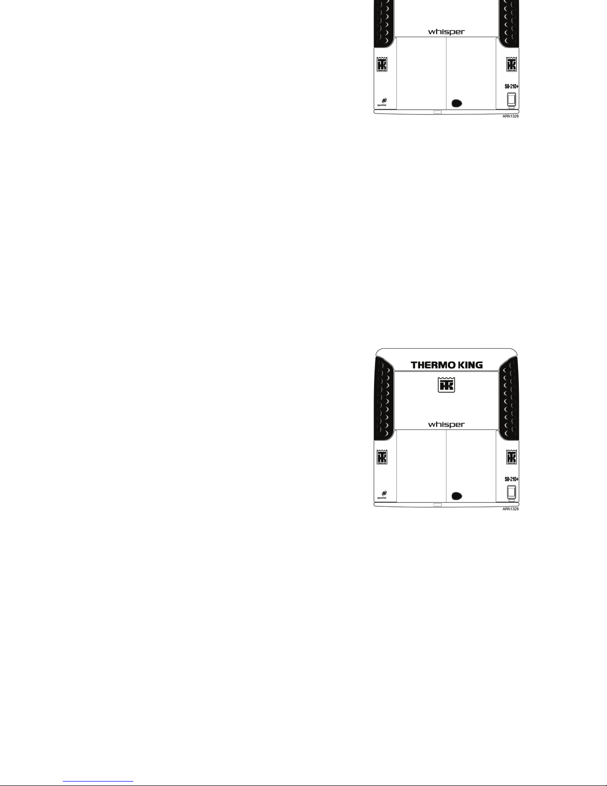
The Thermo King SB-210+/310+ is a one piece,
self-contained, diesel powered, air cooling/heating unit
operating under the control of a SMART REEFER 2 (SR-2)
programmable microprocessor controller. The unit mounts on
the front of the trailer with the evaporator extending through an
opening in the front wall.
The SB-210+/310+ features cooling and heating using a quiet
running engine from the Thermo King TK486 engine family.
The SB-210+ and SB-310+ are available in the following three
models:
SB-210+ 30: Cooling and heating on diesel engine
operation.
SB-210+ 50: Cooling and heating on diesel engine operation
and electric standby operation.
SB-310+ 30: High capacity cooling and heating on diesel
engine operation. Designed for engine operation at a high
speed of 2600 rpm.
The Electronic Throttling Valve (ETV) provides enhanced
control of the refrigeration system. The ETV is optional on the
SB-210+ and standard on the SB-310+. See “Electronic
Throttling Valve” on page 28.
Figure 7: Front View
23
Unit Description
Unit Overview
The Thermo King SB-210+/310+ is a one piece,
self-contained, diesel powered, air cooling/heating unit
operating under the control of a SMART REEFER 2 (SR-2)
programmable microprocessor controller. The unit mounts on
the front of the trailer with the evaporator extending through an
opening in the front wall.
The SB-210+/310+ features cooling and heating using a quiet
running engine from the Thermo King TK486 engine family.
The SB-210+ and SB-310+ are available in the following three
models:
SB-210+ 30: Cooling and heating on diesel engine
operation.
SB-210+ 50: Cooling and heating on diesel engine operation
and electric standby operation.
SB-310+ 30: High capacity cooling and heating on diesel
engine operation. Designed for engine operation at a high
speed of 2600 rpm.
The Electronic Throttling Valve (ETV) provides enhanced
control of the refrigeration system. The ETV is optional on the
SB-210+ and standard on the SB-310+. See “Electronic
Throttling Valve” on page 28.
Figure 7: Front View
Page 25

Unit Description
24
In addition to the quiet TK486 engine, the SB-210+/310+
includes other sound deadening components as standard and
optional equipment. Among them are a special exhaust system,
sound-proof insulation, special door gaskets and
sound-absorbing doors. See the Design Features list below.
Design Features
The following chart lists key design features and options.
● Standard Features
❍ Option/Factory installed
❏ Option/Dealer Installed
SB-210+/310+ Key
Features & Options
SB-210+
Model
30
SB-210+
Model
50
SB-310+
Model
30
SMART REEFER SR-2
Controller
●●●
OptiSet™ Plus with
FreshSet™
Programmable Modes
●●●
ETV (Electronic Throttling
Valve)
❍❍●
ServiceWatch™ Data
Logger
●●●
CargoWatch™ Data
Logger
●●●
CargoWatch™
Accessories:
• Door Switches ❍ / ❏❍ / ❏❍ / ❏
• Temperature Sensor
Kits
❍ / ❏❍ / ❏❍ / ❏
EMI-3000
●●●
High-Capacity Condenser
Coil
●●●
Whisper Quiet Technology
❍❍❍
Easy-access door design
●●●
Composite Exterior
Panels
●●●
SB-210+/310+ Key
Features & Options
SB-210+
Model
30
SB-210+
Model
50
SB-310+
Model
30
Page 26

Unit Description
25
Long-Life Coolant/Silicone
Hoses
●●●
Remote Status Display
❍ / ❏❍ / ❏❍ / ❏
Remote Status Display
with Fuel Level
❏❏❏
Remote Status Display
with Fuel Level and
Temperature
❏❏❏
Standard Unit Color White
●●●
Standard Grille Color
Black
●●●
Directional Air Delivery
●●●
Vibration Isolation System
●●●
Aluminum Undermount
Fuel Tank 50 Gal. (186
Liter)
●●●
Fuel Level Sensor
●●●
Fuel Heater
❍❍❍
SB-210+/310+ Key
Features & Options
SB-210+
Model
30
SB-210+
Model
50
SB-310+
Model
30
Frost Plug Heater
❍❍❍
Alternator, 65 Amp, 12
Vdc
❍❍❍
24 Horsepower Electric
Motor
❍
Special Color Grills
❍❍❍
Fresh Air Exchange
❍❍❍
i-Box™ Interface
❍ / ❏❍ / ❏❍ / ❏
PrimAir™ bulkhead and
duct system
❏❏❏
Rear Remote Control
❏❏❏
Humidity Sensor ❏❏❏
Megatech Battery,
12 Volt, Wet Cell
❏❏❏
EON Battery,
12 Volt, Dry Cell
❏❏❏
SB-210+/310+ Key
Features & Options
SB-210+
Model
30
SB-210+
Model
50
SB-310+
Model
30
Page 27
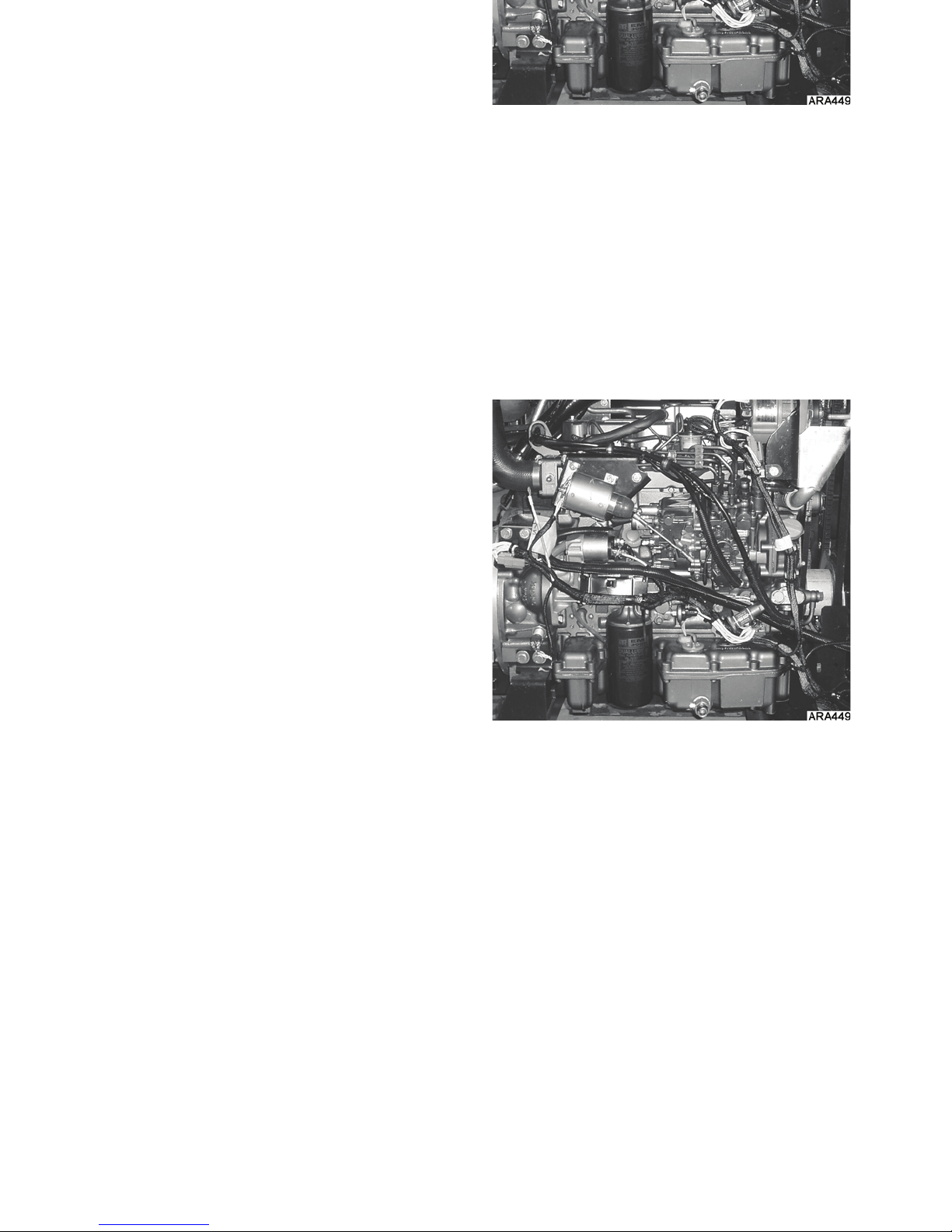
Unit Description
26
Diesel Engine
The Thermo King TK486 family of engines are 4-cylinder,
water cooled, direct injection diesel engines. The engine is
coupled directly to the compressor on the Model 30. A
centrifugal clutch transfers power from the engine to the
compressor on the Model 50. Belts transmit power to the unit
fans, alternator and water pump.
The SB-210+ uses a TK486V (Tier2), which is designed to run
with a high speed of 2200 rpm.
The SB-310+ uses a TK486VH (Tier2), which is designed to
run with a high speed of 2600 rpm.
Figure 8: TK486V (TK486VH is Similar) Tier 2
Page 28

Unit Description
27
ELC (Extended Life Coolant)
ELC (Extended Life Coolant) is standard equipment. The
maintenance interval for ELC is five years or 12,000 hours. A
nameplate on the coolant expansion tank identifies units with
ELC (see “Safety Decals and Locations”). The new engine
coolant, Chevron Extended Life Coolant, is RED in color
instead of the previous GREEN or BLUE-GREEN colored
conventional coolants.
NOTE: The use of 50/50% pre-mixed ELC is recommended
to assure that de-ionized water is being used. If 100% full
strength concentrate is used, de-ionized or distilled water is
recommended instead of tap water to insure the integrity of
the cooling system is maintained.
EMI 3000
EMI 3000 is an extended maintenance interval package. It is
standard equipment. The EMI 3000 package consists of the
following key components:
• EMI 3000-Hour Cyclonic Air Cleaner Assembly and Air
Cleaner Element
• EMI 3000-Hour Fuel Filter (black with gold lettering)
• EMI 3000-Hour Dual Element Oil Filter (black with gold
lettering)
• API Rating CI-4 Mineral Oil
• Five Year or 12,000 Hour ELC (Extended Life Coolant)
The EMI package allows standard maintenance intervals to be
extended to 3,000 hours, or 2 years, whichever occurs first.
NOTE: Units equipped with the EMI 3000 package do
require regular inspection in accordance with Thermo King's
maintenance recommendations.
NOTE: The new EMI 3000 oil filters and new EMI 3000 air
cleaners are NOT interchangeable with the older style oil
filters and air cleaners.
CAUTION: Do not add “GREEN” or
“BLUE-GREEN” conventional coolant to cooling
systems using “RED” Extended Life Coolant, except
in an emergency. If conventional coolant is added to
Extended Life Coolant, the coolant must be changed
after 2 years instead of 5 years.
Page 29
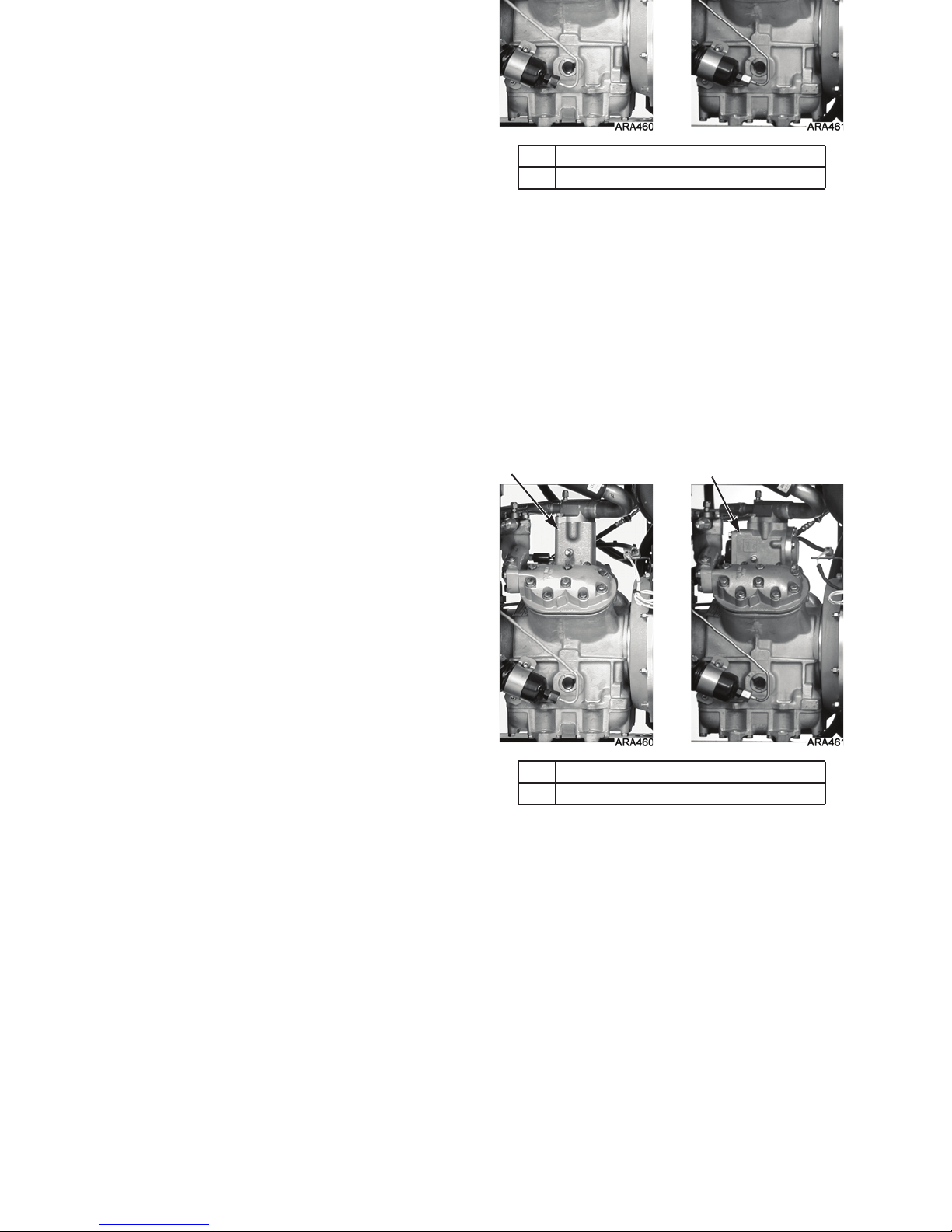
Unit Description
28
Thermo King X430L
Reciprocating Compressor
The unit is equipped with a Thermo King X430L reciprocating
compressor with 30 cu. in. (492 cm
3
) displacement.
Electronic Throttling Valve
The Electronic Throttling Valve (ETV) is optional on the
SB-210+ and standard on the SB-310+.
The ETV provides enhanced control of the refrigeration system
as follows:
• Allows the refrigeration system to fully utilize the power
capabilities of the engine under varying conditions
• Provides an additional measure of protection against high
discharge pressures
• Protects the engine from high coolant temperature
shutdowns
• Provides a means of precise temperature control.
You can tell if the unit has an ETV by looking at the
compressor. Units with an ETV have a suction valve adapter.
Units without an ETV have a mechanical throttling valve.
1. Suction Valve Adapter (Has ETV)
2. Mechanical Throttling Valve (No ETV)
Figure 9: Compressors
1 2
Page 30

Unit Description
29
SMART REEFER 2 (SR-2) Control
System
The SR-2 controller is a microprocessor control system
designed for transport refrigeration. The SR-2 integrates the
following functions: changing setpoint and operating mode,
viewing gauge, sensor and hourmeter readings, initiating
defrost cycles, and viewing and clearing alarms.
The microprocessor components are located inside the control
box, which is located inside the lower roadside service door.
The microprocessor is connected to an HMI (Human Machine
Interface) Control Panel. It is used to operate the unit. The
HMI control panel is mounted on the face of the control box. It
is clearly visible through an opening in the lower roadside
service door.
See “Operating Instructions” for more information about the
SR-2 controller.
Depending on the air temperature in the trailer, as sensed by
the microprocessor controller, the unit will typically operate in
one of the following modes:
CYCLE-SENTRY Operation
• High Speed Cool
• Low Speed Cool
• Null (Engine Off)
• Low Speed Heat
• High Speed Heat
•Defrost
Continuous Run Operation
• High Speed Cool
• Low Speed Cool
• Low Speed Modulated Cool (Optional SB-210+)
• Low Speed Modulated Heat (Optional SB-210+)
• Low Speed Heat
• High Speed Heat
•Defrost
Page 31

Unit Description
30
CYCLE-SENTRY Start-Stop Controls
The CYCLE-SENTRY Start-Stop fuel saving system provides
optimum operating economy.
The CYCLE-SENTRY system automatically starts the unit on
microprocessor demand, and shuts down the unit after those
conditions are satisfied.
The system automatically monitors and maintains the
compartment temperature, engine block temperature, and
battery charge levels at a condition where quick, easy starts are
possible.
WARNING: The unit can start at any time without
warning. Press the O
FF
key on the HMI control panel
and place the microprocessor On/Off switch in the
Off position before inspecting or servicing any part of
the unit.
Your Thermo King unit provides a wide range
of control and programming flexibility.
However, pre-programming of the unit
controller may prohibit operation in certain
temperature ranges within some modes and
may also prohibit certain modes of operation.
If you have controller programming questions,
contact your supervisor or your Thermo King
dealer before requesting service.
Page 32

Unit Description
31
Data Logging
There are two separate data loggers. The data is downloaded
through the data ports on the front of the control box using an
IBM
®
PC compatible laptop or desktop computer and Thermo
King WinTrac 4.6 (or higher) software.
ServiceWatch™: ServiceWatch™ is standard equipment. It
records operating events, alarm codes and compartment
temperatures as they occur and at preset intervals. This
information is typically used to analyze unit performance. Use
the ServiceWatch Port to downloaded the ServiceWatch data.
CargoWatch™: CargoWatch™ data logging requires the
installation of optional sensors. Up to six temperature
sensor/probes and four door switches can be installed.
CargoW atch als o logs the setpoint. Use the CargoWatch Port to
downloaded the CargoWatch data. If optional temperature
sensors are installed, their readings are displayed as Datalogger
Sensor (1-6) T emperature in the sensor readings. See “Viewing
Sensor Readings” on page 75.
A printer can also be used to print a report of the optional
sensor readings. See “Printing a Trip Report” on page 90.
1. CargoWatch Port
2. ServiceWatch Port
Figure 10: HMI Controller and Data Ports
21
Page 33

Unit Description
32
OptiSet Plus
OptiSet™ Plus is a group of programmable functions that
control how the unit will operate with specific setpoints or
named products. This assures that when a particular setpoint or
named product is selected, the unit will always operate the
same way. This allows an entire fleet to be configured to match
the customers’ needs. Contact your Thermo King dealer for
information about programming OptiSet Plus.
FreshSet
FreshSet™ is included in OptiSet Plus. FreshSet is a demand
base temperature control for fresh products. FreshSet modifies
and adjusts unit airflow operation to control temperature and to
maximize protection of cargo, while keeping operating costs to
a minimum. Contact your Thermo King dealer for information
about programming FreshSet.
Defrost
Frost gradually builds-up on evaporator coils as a result of
normal operation. The unit uses hot refrigerant to defrost the
evaporator coil. Hot refrigerant gas passes through the
evaporator coil and melts the frost. The water flows through
collection drain tubes onto the ground. The methods of defrost
initiation are Automatic, and Manual.
Automatic Defrost: The controller automatically initiates
timed or demand defrost cycles. The controller can be
programmed to initiate timed defrost cycles at intervals of 2, 4,
6, 8, or 12 hours. Demand defrost cycles occur if the
differences between the return air temperature, discharge air
temperature, and coil temperature exceed certain limits. The
unit can enter defrost cycles as often as every 30 minutes if
required.
Manual Defrost: In Manual Defrost mode, the operator
initiates a defrost cycle. See “Initiating a Manual Defrost
Cycle” on page 71.
Page 34

Unit Description
33
NOTE: The unit will not perform a Manual Defrost Cycle
unless the unit has been turned on with the O
N
key, the unit
is running in Continuous or CYCLE-SENTRY Mode (or shut
down in CYCLE-SENTRY Null Mode), and the coil
temperature is below 45 F (7 C).
Unit Description
33
NOTE: The unit will not perform a Manual Defrost Cycle
unless the unit has been turned on with the O
N
key, the unit
is running in Continuous or CYCLE-SENTRY Mode (or shut
down in CYCLE-SENTRY Null Mode), and the coil
temperature is below 45 F (7 C).
Page 35

Unit Description
34
Opening the Front Doors
Pull the door latch handle to open the door and access the
engine compartment.
Opening the Secondary Door Latch
These units are also equipped with a secondary door latch. A
secondary door latch nameplate is located below the front
doors. After opening the door latch, reach between the front
doors and lift the spring latch over the spring catch while
opening the door.
1. Door Latch
2. Secondary Door Latch Nameplate
Figure 11: Door Latch Location
1
2
1. Spring Latch
2. Spring Catch
Figure 12: Opening Secondary Door Latch
1
2
Page 36

Unit Description
35
Closing the Front Doors
Slam the door to close it. Do not push the door closed while
holding the door latch handle open or the door will not close
properly.
Unit Description
35
Closing the Front Doors
Slam the door to close it. Do not push the door closed while
holding the door latch handle open or the door will not close
properly.
Page 37

Unit Description
36
Engine Compartment Components
The following maintenance items can be checked visually.
Air Filter Restriction Indicator: The air filter restriction
indicator is attached to the engine intake manifold. When the
diaphragm indicates 25, service the air filter. Press the button
on the bottom of the restriction indicator to reset after servicing
the air cleaner.
Compressor Oil Sight Glass: Use this sight glass to check
the compressor oil level. Check the compressor oil when there
is evidence of oil loss (leaks). Refer to the unit Maintenance
Manual for the correct procedure.
Engine Oil Dipstick: Use the engine oil dipstick to check
the engine oil level.
1. Air Filter Restriction Indicator
2. Receiver Tank Sight Glass
3. Engine Oil Dipstick
4. Compressor Oil Sight Glass
Figure 13: Engine Compartment
21
34
WARNING: The unit can start at any time without
warning. Press the O
FF
key on the HMI control panel
and place the microprocessor On/Off switch in the
Off position before inspecting any part of the unit.
CAUTION: Make sure the engine is turned off before
attempting to check the engine oil.
Page 38

Unit Description
37
Receiver Tank Sight Glass: This sight glass indicates the
level of refrigerant in the receiver tank.
Operate the unit in high speed cool for approximately 15
minutes to stabilize operating conditions and temperature
before attempting to check the refrigerant.
NOTE: If the ball floats, there is sufficient refrigerant in the
unit for that load at that particular trailer temperature. This
test does not determine if the unit contains a full charge or an
overcharge of refrigerant.
Unit Protection Devices
Fuse Link (Current Limiter): The fuse link is located in the
positive battery cable. The fuse link protects the electric
system from a short. If the fuse link burns out, replace it by
replacing the positive battery cable.
High Pressure Cutout Switch: The high pressure cutout
switch (HPCO) is located on the compressor discharge
manifold. If the compressor discharge pressure becomes
excessive, the switch opens the circuit to the run relay to stop
the unit. The microprocessor will record Alarm Code 10.
High Pressure Relief Valve: This valve is designed to
relieve excessive pressure in the refrigeration system. It is
located on the receiver tank. If the high pressure relief valve
opens, much of the refrigerant will be lost. Take the unit to a
Thermo King dealer if this occurs.
Low Oil Level Switch: The low oil level switch closes if the
oil drops below an acceptable level. If it stays closed for a
specified time, the microprocessor shuts the unit down and
records Alarm Code 66.
Low Oil Pressure Switch: The low oil pressure switch
closes if the oil pressure drops below an acceptable level. If it
stays closed for a specified time, the microprocessor shuts the
unit down and records alarm code 19.
Preheat Buzzer: The preheat buzzer sounds when the
controller energizes the preheat relay. This warns anyone near
the unit that the controller is about to start the engine.
Page 39

Unit Description
38
Overload Relay—Manual Reset (Model 50): An
overload relay protects the standby electric motor. The
overload relay opens the circuit to the electric motor if the
motor overloads for any reason (e.g., low line voltage or
improper power supply) while the unit is on electric standby
operation. The microprocessor will record Alarm Code 90.
Press the reset button on the high voltage tray to reset the
overload relay . The high voltage tray is located behind the
lower access panel on the compressor side of the unit.
Smart FETs: Smart FETs in the controller interface board
protect some circuits and components from an overcurrent
condition.
Fuses: A number of fuses, located on the interface board,
protect various circuits and components. The interface board is
located inside the control box. Refer to the appropriate
Microprocessor Controller Diagnostic Manual for more
information about the fuses.
Fuse Size Function
F2 15A 2AB Power
F3 40A Fuel Sol Pull-In/Starter Circuit
F4
None2ANo Fuse - All Bosch and Thermo King
Alternators
2A Fuse - All Prestolite Alternators
F5 60A Preheat Circuit
F6 15A Damper and High Speed Circuits
F7 2A
8XP Circuit - Controller On Feedback to
HMI
F8 5A CAN Connector J12
F9 5A CAN Connector J14
F10 10A 8X Power (Install fuse in upper position)
F11 10A Power to LLS1 (Not Used)
F12 5A CAN Connector J13
F13 2A 8FC Circuit (Remote Lights)
F15 P/S On/Off Relay
F20 2A Alternator Sense
F22 Not Used
F23 Not Used
Fuse Size Function
Page 40

Unit Description
39
F25 7.5A HPCO Switch Circuit
F4 Remove fuse F4 for Model 30 units with Australian
Bosch or Thermo King Alternators. Install fuse F4 for
Model 50 units with Prestolite Alternator.
F5 The F5 preheat fuse is a “slow blow” type. It is
designed for use with the Ya nmar engine air heater.
Always replace the fuse with the TK specified fuse.
F10 When fuse F10 is installed in the upper position the
On/Off keys on the HMI turn the unit on and off. When
fuse F10 is installed in the lower position the unit will
start and run without the HMI control panel.
F15 The device identified as F15 is a poly switch. These
over-current devices reset automatically and are not
replaceable.
Fuse Size Function
1. Control Box
Figure 14: Control Box With Service Door Open
1
Page 41

Unit Description
40
Figure 16: Interface Board
1. Interface Board
Figure 15: Control Box With Control Box Door Open
1
Unit Description
40
Figure 16: Interface Board
1. Interface Board
Figure 15: Control Box With Control Box Door Open
1
Page 42

41
Remote Status Display (Optional)
The remote status display mounts on the cargo box for easy
viewing of the unit’s mode.
Figure 17: Remote Status Display (All LEDs Shown)
The remote status display indicates operating status as follows:
White Status LEDs: Illuminate the “T” portion of the TK
logo when the unit is functioning properly with no alarm
codes.
Figure 18: Normal Operation No Alarms
Page 43

Remote Status Display (Optional)
42
Amber Status LEDs: Illuminate the “K” portion of the TK
logo when the unit has a check alarm code, but is still
functioning properly. Check the unit as soon as possible to
correct the alarm condition.
Figure 19: Check Alarm
White and Amber Status LEDs: The two bottom LEDs in
the “T” (in white) and the four bottom LEDs in the “K” (in
amber) are illuminated when the unit has a shutdown alarm
code and the load integrity is at risk. Correct the alarm
condition immediately.
Figure 20: Shutdown Alarm
Page 44

Remote Status Display (Optional)
43
Remote status displays that also show the fuel level or the fuel
level and the box temperature are also available. The number
of white LEDs illuminated in the fuel level indicator show the
fuel level. When the fuel level falls below 10%, only the two
amber LEDs at the top and bottom of the fuel level indicator
are illuminated to indicate the low fuel level.
The temperature display shows the box temperature, except
when the unit is in defrost in which case it displays “dF”.
1. Status Indicator
2. Fuel Level Indicator
Figure 21: Remote Status Display with Fuel Level
1
2
1. Status Indicator
2. Fuel Level Indicator
3. Temperature Display
Figure 22: Remote Status Display
with Fuel Level and Temperature
1
2
3
Page 45

Remote Status Display (Optional)
44
Remote Status Display (Optional)
44
Page 46

45
Manual Pretrip Inspection
(Before Starting the Unit)
Pretrip inspections are an important part of a preventative
maintenance program designed to minimize operati ng
problems and breakdowns. Perform this pretrip inspection
before every trip involving refrigerated cargo.
NOTE: Pretrip inspections are not intended to take the place
of regular maintenance inspections.
Fuel: Make sure the diesel fuel supply is adequate to
guarantee engine operation to the next check point. Allow for
maximum fuel consumption of one gallon per hour of engine
operation.
Engine Oil: Check the engine oil level. It should be at the
Full mark when the dipstick is threaded all the way into the oil
pan. Do not overfill.
Engine Coolant: The engine coolant must have antifreeze
protection to -30 F (-34 C). Add coolant if Alarm Code 37 is
active. Check and add coolant to the expansion tank.
Battery: Make sure the battery terminals are tight and free of
corrosion.
Belts: Make sure belts are in good condition and adjusted to
the proper tension. For more information about belt tension,
see the Specifications chapter.
Electrical: Check the electrical connections to make sure they
are securely fastened. Wires and terminals should be free of
corrosion, cracks, and moisture.
Structural: Visually inspect the unit for leaks, loose or
broken parts, and other damage.
CAUTION: Turn the engine off before checking the
engine oil level.
WARNING: Do not remove the expansion tank cap
while the coolant is hot.
Page 47

Manual Pretrip Inspection (Before Starting the Unit)
46
Damper: Make sure the damper in the evaporator air outlets
move freely, with no sticking or binding.
Coils: Make sure the condenser and evaporator coils are clean
and free of debris.
Cargo Box: Check the interior and exterior of the cargo box
for damage. Any damage to the walls or insulation must be
repaired.
Cargo Doors: Make sure that the cargo doors and weather
seals are in good condition. The doors should latch securely
and the weather seals should fit tightly.
Defrost Drains: Check the defrost drain hoses and fittings to
make sure they are open.
Page 48

47
Operating Instructions
Figure 23: SR-2 HMI Control Panel
SMART REEFER 2 (SR-2)
Controller Overview
Thermo King has applied the latest advances in computer
technology to develop a device that controls temperature and
unit function, and displays operating information quickly and
accurately.
There is nothing complicated about learning to operate the
SR-2 Controller, but you will find that a few minutes studying
the contents of this manual will be time well spent.
WARNING: Do not operate the unit until you are
completely familiar with the location and function of
each control.
Page 49

Operating Instructions
48
The microprocessor components are located inside the control
box, which is located inside the lower roadside service door.
The microprocessor is connected to an HMI (Human Machine
Interface) Control Panel. It is used to operate the unit. The
CargoWatch and ServiceWatch ports are used to retrieve data
from the data logging system.
Microprocessor On/Off Switch: This switch supplies or
removes electrical power to the microprocessor . It is located on
the left side of the control box. See Figure 24.
1. Control Box 4. CargoWatch Port
2. Microprocessor
On/Off Switch
5. HMI Control Panel
3. ServiceWatch Port
Figure 24: Control Box With Service Door Open
5
2
1
3
4
WARNING: The unit can start at any time without
warning. Press the O
FF
key on the HMI control panel
and place the microprocessor On/Off switch in the
Off position before inspecting or servicing any part of
the unit.
Page 50

Operating Instructions
49
HMI Control Panel
The HMI control panel has a display and eight touch sensitive
keys. The display is capable of showing both text and graphics.
The four keys on the left and right sides of the display are
dedicated keys. The four keys under the display are “soft”
keys. The function of “soft” keys change depending on the
operation being performed. If a soft key is active, its function
will be shown in the display directly above the key.
Control Panel Display
The display is used to supply unit information to the operator.
This information includes setpoint, current box temperature
operating information, unit gauge readings, system
temperatures and other information as selected by the operator.
The default display is called the Standard Display. It is shown
in Figure 25 and will be described in detail later in this chapter.
1. On Key (Dedicated Key)
2. Off Key (Dedicated Key)
3. Display
4. Defrost Key (Dedicated Key)
5. Mode Key (Dedicated Key)
6. Soft Keys
Figure 25: Control Panel Display and Keys
1
2
3
4
5
6
Page 51

Operating Instructions
50
Control Panel Keys
The four keys on the left and right sides of the display screen
are “dedicated keys” (see Figure 25). Their functions are listed
below.
On Key: Press this key to turn the unit on. The
Thermo King Logo screen will appear briefly.
The display will then show the Standard Display
of box temperature and setpoint when the unit is
ready to run.
Off Key: Press this key to turn the unit off. The
engine will stop immediately. Then the HMI
control panel will enter the power-down
sequence.
Defrost Key: Press this key to initiate a Manual
Defrost cycle.
Mode Key: Press this key to switch back and
forth between the CYCLE-SENTRY mode and
the Continuous Run mode.
The four “soft” keys under the display are
multi-purpose keys (see Figure 25). Their
function changes depending on the operation
being performed. If a soft key is active, it’s
function will be shown in the display directly
above the key.
Typical soft key applications:
• Set Point
• Gauges
• Sensors
• Menu
• Next/Back
• Yes/No
• +/–
• Up/Down
• Select/Exit
• Clear/Help
Page 52

Operating Instructions
51
Turning Unit On
Complete the following steps to turn on the unit:
1. Press the O
N
key. See Figure 26.
2. The display briefly shows a Thermo King Logo. See
Figure 27.
NOTE: With extremely cold ambient temperatures it may
take up to 15 seconds for the first display to appear.
3. The “Configuring System” Screen briefly appears while
communications are established between the
microprocessor and the HMI control panel.
4. The Standard Display showing box temperature and
setpoint briefly appears.
5. The “Diesel Engine Starting” Screen briefly appears as the
engine preheats and starts.
6. The Standard Display showing box temperature and
setpoint reappears when the unit is running.
1. On Key
2. Display
Figure 26: Press On Key
1
2
Page 53

Operating Instructions
52
Figure 27: Turning Unit On Screen Sequence
Operating Instructions
52
Figure 27: Turning Unit On Screen Sequence
Page 54

Operating Instructions
53
Turning Unit Off
Complete the following steps to turn unit off:
1. Press the O
FF
key.
2. The engine will immediately shut off.
3. The “System is Powering Down” Screen will briefly
appear.
4. The Off Screen will briefly appear.
5. The screen goes blank when the unit power is off.
Figure 29: Turning Unit Off Screen Sequence
1. Off Key
2. Display
Figure 28: Press Off Key
1
2
Page 55

Operating Instructions
54
Standard Display
The Standard Display is the default display. It appears if no
other display function is selected. The Standard Display shows
the box temperature and setpoint. The box temperature is
measured by the controlling sensor . The return air sens or is the
controlling sensor except when the controller is programmed to
use the discharge air sensor as the controlling sensor during
modulation. The box temperature shown below in Figure 30 is
35.5 F. The setpoint shown is 35 F. The CYCLE-SENTRY
Icon in the upper right corner of the display shows the unit is
operating in the CYCLE-SENTRY mode. The arrow pointing
down indicates the unit is cooling.
NOTE: The CYCLE-SENTRY icon will appears when the
unit is operating in CYCLE-SENTRY mode as shown below.
If the CYCLE-SENTRY icon is not present the unit is
operating in Continuous mode.
1. Box Temperature 3. CYCLE-SENTRY
Icon
2. Cooling 4. Setpoint
Figure 30: Standard Display
1
4
3
2
Page 56

Operating Instructions
55
Standard Display Variations
The Standard Display has variations. A display showing any of
the following variations is still considered a Standard Display
(see Figure 31).
The top of the display may show a named product if the
controller has been programmed with OptiSet Plus temperature
profiles. The far left soft key may display P
RODUCT
or
P
RODUCT/SETPOINT
if the controller has been programmed
with OptiSet Plus temperature profiles. See “OptiSet Plus” on
page 115 for information about selecting or changing the
named product or the setpoint if the controller has been
programmed with OptiSet Plus temperature profiles. Contact
your Thermo King dealer for information about programming
the controller with OptiSet Plus temperature profiles.
The temperature can be displayed in degrees Fahrenheit (F) or
degrees Celsius (C). An arrow pointing upwards indicates the
unit is heating. An arrow pointing downwards indicates the
unit is cooling.
1. Named Product
2. Heating
3. P
RODUCT
or P
RODUCT/SETPOINT
Soft Key
4. Degrees Celsius
5. Cooling
6. Degrees Fahrenheit
Figure 31: Standard Display Variations
4
2
1
6
5
3
Page 57

Operating Instructions
56
Temperature Watch Display
The Standard Display defaults to the Temperature Watch
Display after about 2-1/2 minutes of non-use (when no keys
are pressed). The Temperature Watch Display shows the same
box temperature and setpoint but in larger fonts. This creates
easy operator viewing from a distance. To return to the
Standard Display press the M
ENU
soft key (or any of the other
three soft keys that are not assigned).
NOTE: A named product may appear above the temperature
reading if the controller has been programmed with OptiSet
Plus temperature profiles and a named product has been
selected.
NOTE: The CYCLE-SENTRY icon will appear in the
Temperature Watch display when the unit is operating in
CYCLE-SENTRY mode as shown below. If the
CYCLE-SENTRY icon is not present the unit is operating in
Continuous mode.
1. Named Product (If Selected)
2. CYCLE-SENTRY Icon
3. Menu Soft Key
Figure 32: Temperature Watch Display
2
3
1
Page 58

Operating Instructions
57
Alarm Display
If a unit alarm condition occurs the large Alarm Icon will
appear on the Standard Display as shown below in Figure 33.
NOTE: A shutdown alarm will also cause the display and
backlight to flash on and off, and the display will switch from
normal video to reverse video and back to normal video (light
areas become dark and dark areas become light).
See “Alarms Menu” on page 85 for information about
displaying and clearing alarms.
1. Alarm Icon
2. Named Product (If Selected)
Figure 33: Alarm Display
1
2
Page 59

Operating Instructions
58
Starting the Diesel Engine
Diesel engine preheats and starts automatically in both
Continuous Mode and CYCLE-SENTRY mode. The engine
will preheat and start if necessary when the unit is turned on.
The engine preheat and start will be delayed in
CYCLE-SENTRY mode if there is no current need for the
engine to run. If a key or sequence of keys are pressed on the
controller before the engine starts, the engine will preheat and
start approximately 10 seconds after pressing the last key.
See “Turning Unit On” on page 51.
NOTE: Run a pretrip test if the unit has not been used
recently. See “Pretrip Tests” on page 104.
Unit Fails To Start
If the engine does not start and the Alarm Icon appears on the
display, take the following steps.
1. Check for and correct any alarm conditions. See “Viewing
and Clearing Alarms Screen Sequence” on page 87.
2. Clear all alarms. See “Viewing and Clearing Alarms
Screen Sequence” on page 87.
3. Press the O
FF
key to turn the unit off.
4. Press the O
N
key to turn the unit on.
5. The controller will go through the start up screens and
then after a 10 second delay the unit will start
automatically.
6. If the engine will still not start, turn the unit off. Determine
and correct the cause for not starting.
7. Repeat the procedure.
CAUTION: The engine may start automatically any
time the unit is turned on.
WARNING: Never use starting fluid.
Page 60

Operating Instructions
59
After Start Inspection
After the unit is running, check the following items to confirm
that the unit is running properly.
Oil Pressure: Check the engine oil pressure by pressing the
G
AUGES
soft key. See “Viewing Gauge Readings” on page 73.
The Engine Oil Pressure Display should indicate OK not LOW .
Ammeter: Check the ammeter reading by pressing the
G
AUGES
soft key. See “Viewing Gauge Readings” on page 73.
The Amps Display should indicate a positive charge amperage
rate to the battery. A negative (-) number indicates a discharge
condition.
Compressor Oil: The compressor oil level should be visible
in the compressor sight glass after 15 minutes of operation. If
not, check the compressor oil level using the procedure in the
appropriate maintenance manual.
Pre-Cooling: Make sure that the setpoint is at the desired
temperature. See “Changing the Setpoint” on page 65. Allow
the unit to run for a minimum of 30 minutes (longer if possible)
before loading the trailer.
This provides a good test of the refrigeration system while
removing residual heat and the moisture from the trailer
interior to prepare it for a refrigerated load.
Defrost: When the unit has finished pre-cooling the trailer
interior, manually initiate a Defrost cycle. See “Initiating a
Manual Defrost Cycle” on page 71. This will remove the frost
that builds up while running the unit to pre-cool the trailer.
Page 61

Operating Instructions
60
Electric Standby Operation
Model 50 units are equipped with Electric Standby. This
feature allows the unit to operate on electric power as well as
be powered by the standard diesel engine.
During Electric Standby operation, power to the unit is
supplied by an electric motor connected to a high voltage
power source. The required voltage is shown on a decal on the
unit’s electric power receptacle.
Electric Power Receptacle: The electric power receptacle
is used to connect the unit to an appropriate electric power
source for electric standby operation. The electric power
receptacle is located next to the HMI Control Panel. Make sure
the unit and the power supply are turned off before connecting
or disconnecting a power cord.
Figure 34: Electric Power Receptacle
W ARNING: Units equipped with electric standby may
start at any time when the unit is connected to live
electric power and the controller is turned on.
CAUTION: Always turn the electric power supply off
when handling, connecting, or disconnecting high
voltage power cords.
CAUTION: Do not start the electric drive motor
unless the diesel engine is completely stopped.
Page 62

Operating Instructions
61
Starting the Unit on Electric Standby
Operation
Units equipped with the Electric Standby option only.
Electric motor starting is automatic in both Continuous Mode
and Cycle Sentry Mode. The motor will start as required when
the unit is turned on. If any keys are being pressed on the HMI
control panel prior to the motor start, the motor start will be
delayed until 10 seconds after the last key is pressed. Start the
unit on Electric Standby operation as follows:
1. Press the controller O
FF
key to make sure the unit is
turned off.
2. Connect the unit electric power receptacle to an
appropriate electric power supply.
3. Press the controller O
N
key.
4. If a screen asking if you wish to switch to Electric Standby
appears, press the Y
ES
soft key. This screen does not
appear if the controller is programmed to automatically
switch from Diesel to Electric Standby, or if the unit was
in Electric Standby when it was turned off.
Figure 35: Electric Standby Detected Screen
CAUTION: The motor may start automatically any
time the unit is turned on.
Page 63

Operating Instructions
62
5. If the microprocessor determines that the unit should cool
or heat, the motor start screen appears as shown below.
The preheat buzzer sounds for 20 seconds before the
electric motor starts. It may not start if the return air sensor
temperature is within a few degrees of setpoint. The
electric motor cycles on and off in CYCLE-SENTRY
Mode and runs continuously in Continuous Mode.
Figure 36: Electric Motor Starting Screen
6. Complete an After Start Inspection (see page 59).
Unit Fails to Start
If the electric motor does not start and the Alarm Icon appears
on the display, take the following steps.
1. Check for and correct any alarm conditions. See “Viewing
and Clearing Alarms Screen Sequence” on page 87.
2. Clear all alarms. See “Viewing and Clearing Alarms
Screen Sequence” on page 87.
3. Press the Controller O
FF
key.
4. Press the Controller O
N
key.
5. If the unit still does not start, repeat the above steps.
ELECTRIC MOTOR STARTING
ARA909
Page 64

Operating Instructions
63
Switching from Diesel to Electric
Units equipped with the Electric Standby option only
If the Diesel to Electric Autoswitch Enabled feature in
Guarded Access is set YES then the unit will automatically
switch to Electric Mode operation when standby power is
connected and available.
If the Diesel to Electric Autoswitch Enabled feature in
Guarded Access is set NO, then the prompt screen shown
below will appear when standby power is connected and
available.
Figure 37: Electric Standby Detected Screen
If YES is selected then the display will briefly show the screen
below.
Figure 38: Programming Electric Standby Screen
Electric Mode operation will briefly be confirmed. If unit
operation is required the electric motor will start as shown in
“Starting the Unit on Electric Standby Operation” on page 61.
Page 65

Operating Instructions
64
Switching from Electric to Diesel
Units equipped with the Electric Standby option only
If the Electric to Diesel Autoswitch Enabled feature in
Guarded Access is set YES then the unit will automatically
switch to Diesel Mode operation when standby power is turned
off or is no longer available.
If the Electric to Diesel Autoswitch Enabled feature in
Guarded Access is set NO then the prompt screen shown below
will appear when standby power is turned off or is no longer
available.
Figure 39: Electric Standby Undetected Screen
If YES is selected then the display will briefly show the screen
below.
Figure 40: Programming Diesel Mode Screen
Diesel Mode operation will briefly be confirmed. If unit
operation is required the diesel engine will start as shown in
“Starting the Diesel Engine” on page 58.
ELECTRIC STANDBY UNDETECTED
DO YOU WISH TO SWITCH TO
DIESEL?
NOYES
ARA910
PROGRAMMING DIESEL MODE
PLEASE WAIT
ARA911
Page 66

Operating Instructions
65
Changing the Setpoint
To change the setpoint complete the following steps.
NOTE: If the S
ETPOINT
soft key (far left) displays P
RODUCT
or P
RODUCT/SETPOINT
, the controller has been programmed
with OptiSet Plus temperature profiles. See “OptiSet Plus”
on page 115 for information about selecting or changing the
named product or the setpoint.
1. Begin at the Standard Display.
If the Temperature Watch Display is showing, press the
M
ENU
soft key once to return to the Standard Display.
2. Press the S
ETPOINT
soft key on the Standard Display. See
Figure 41. The “Setpoint” Screen briefly appears, then the
“Current Setpoint” Screen appears. See Figure 42.
3. Press the + or - soft keys to change the setpoint reading.
See Figure 42.
4. Press the Y
ES
or NOsoft key accordingly as described
below. See Figure 42.
•If the N
O
key is pressed the setpoint change made with the
“+” or “-” soft keys will not be accepted, the setpoint will
not be changed and the display will return to the Standard
Display.
•If the Y
ES
soft key is pressed, the setpoint change made
with the “+” or “-” soft keys will be accepted, and the
following screens will appear.
1. Standard Display
2. Setpoint Soft Key
Figure 41: Changing Setpoint
1
2
Page 67

Operating Instructions
66
NOTE: Alarm Code 127 “Setpoint Not Entered” may be
generated if the + or - soft keys are used to change the
setpoint, but the Y
ES
or NO soft keys are not used to
accept or decline the new setpoint.
5. The “Programming New Setpoint” Screen will appear. See
Figure 42.
6. The “New Setpoint Is XX” Screen briefly appears. See
Figure 42.
7. The Standard Display appears with setpoint changed to the
new setpoint. See Figure 42.
Page 68

Operating Instructions
67
Figure 42: Changing the Setpoint Screen Sequence
If YES Key was pressed If NO Key was pressed
S
ETPOINT
Key
+ or – Key
Y
ES
or NO Key
Operating Instructions
67
Figure 42: Changing the Setpoint Screen Sequence
If YES Key was pressed If NO Key was pressed
S
ETPOINT
Key
+ or – Key
Y
ES
or NO Key
Page 69

Operating Instructions
68
Selection of Operating Modes
The Thermo King CYCLE-SENTRY system is designed to
save refrigeration fuel costs. The savings vary with the
commodity, ambient temperatures and trailer insulation.
However, not all temperature controlled products can be
properly transported using CYCLE-SENTRY operation.
Certain highly sensitive products normally require continuous
air circulation.Use the following guidelines to select the proper
operating mode to protect the commodity you are transporting.
Examples of products normally acceptable for
CYCLE-SENTRY Operation:
• Frozen foods (in adequately insulated trailers)
• Boxed or processed meats Poultry
•Fish
• Dairy products
• Candy
• Chemicals
•Film
• All non-edible products.
Examples of products normally requiring Continuous Run
Operation for air flow:
• Fresh fruits and vegetables, especially asparagus,
bananas, broccoli, carrots, citrus, green peas, lettuce,
peaches, spinach, strawberries, sweet corn, etc.
• Non-processed meat products (unless pre-cooled to
recommended temperature).
• Fresh flowers and foliage.
The above listings are not all inclusive. Consult your grower or
shipper if you have any questions about the operating mode
selection of your type of load.
Page 70

Operating Instructions
69
Selecting CYCLE-SENTRY or
Continuous Mode
When CYCLE-SENTRY mode is selected the unit will start
and stop automatically to maintain the setpoint, keep the
engine warm, and the battery charged. When Continuous mode
is selected, the unit will start automatically and run
continuously to maintain setpoint and provide constant airflow.
CYCLE-SENTRY or Continuous may not be available if
OptiSet Plus is in use.
If allowed by OptiSet Plus, complete the following steps to
change modes:
NOTE: The mode can also be changed using the Mode Menu
Screen in the Main Menu. See “Turning CYCLE-SENTRY
On or Off” on page 97.
1. Press the M
ODE
key. See Figure 43.
2. The “Programming Continuous Mode” or “Programming
CYCLE-SENTRY Mode” Screen briefly appears. See
Figure 44 and Figure 45.
3. The “New System Mode is Continuous” Screen or the
“New System Mode CYCLE-SENTRY” Screen briefly
appears. See Figure 44 and Figure 45.
4. The Standard Display appears showing the new mode. See
Figure 44 and Figure 45.
5. Press the M
ODE
key again to change the unit back to the
previous mode.
1. CYCLE-SENTRY Icon Shows Mode Selected
Displayed for CYCLE-SENTRY Mode
Not Displayed for Continuous Mode
2. Mode Key
Figure 43: Changing Mode
1
2
Page 71

Operating Instructions
70
Figure 44: Screen Sequence for Changing from
CYCLE-SENTRY Mode to Continuous Mode
Figure 45: Screen Sequence for Changing from
Continuous Mode to CYCLE-SENTRY Mode
Operating Instructions
70
Figure 44: Screen Sequence for Changing from
CYCLE-SENTRY Mode to Continuous Mode
Figure 45: Screen Sequence for Changing from
Continuous Mode to CYCLE-SENTRY Mode
Page 72

Operating Instructions
71
Initiating a Manual Defrost Cycle
Defrost cycles are usually initiated automatically based on time
or temperature. Manual Defrost is also available if the unit is
running and the coil temperature is less than 45 F (7 C). Other
features such as door switch settings may not allow Manual
Defrost to be initiated.
Use the following steps to initiate a Manual Defrost:
1. Press the D
EFROST
key. See Figure 46.
2. The “Defrost” Screen briefly appears. See Figure 47.
3. The “Programming Defrost” Screen briefly appears. See
Figure 47.
4. The “Defrost Started” Screen briefly appears. See Figure
47.
1. St andard Display
2. Defrost Key
Figure 46: Initiating a Manual Defrost Cycle
1
2
Page 73

Operating Instructions
72
5. A modified Standard Display appears. The bar indicator
will fill in showing time remaining to complete the
Defrost cycle. The bar indicator in the figure shows that
the Defrost cycle is 50% complete. When the Defrost
cycle is complete the display returns to the Standard
Display . See Figure 47.
If the unit is prevented from going into a Manual Defrost
(IE: Coil temperature more than 45 F (7 C) or on economy
mode etc.). A “Defrost Unavailable” Screen briefly
appears. The display returns to the Standard Display. See
Figure 47.
Terminating a Defrost Cycle
The Defrost cycle will terminate automatically when the coil
temperature reaches 58 F (14 C), or when the defrost timer
expires. The defrost timer is normally set for 45 minutes, but
can be set for 30 minutes. Defrost can also be terminated by
turning the unit off.
NOTE: If the defrost timer consistently terminates Defrost
because the evaporator coil temperature fails to reach 58 F
(14 C), have the unit checked by a Thermo King dealer to see
if it is working properly.
Figure 47: Initiating Manual Defrost Screen Sequence
or
Page 74

Operating Instructions
73
Viewing Gauge Readings
Use the following steps to view the gauge readings:
1. Begin at the Standard Display.
If the Temperature Watch Display is showing, press the
M
ENU
soft key once to return to the Standard Display.
2. Press the G
AUGES
soft key to enter the Gauges Menu. See
Figure 48.
3. Press B
ACK
or N
EXT
soft keys to scroll through following
gauges: Coolant Temperature, Coolant Level, Oil
Pressure, Oil Level, Amps, Battery Voltage, Engine RPM,
Fuel Level Sensor, Discharge Pressure, Suction Pressure,
ETV Position, and I/O. Selecting I/O enters a group of
screens that are used only by technicians. See Figure 49. If
no keys are pressed within 30 seconds, the screen will
return to the standard display.
NOTE: Units without an Electronic Throttling Valve
(ETV) will not display the Discharge Pressure, Suction
Pressure, and ETV Position. See “Electronic Throttling
Valve” on page 28 for more information about the ETV
and how to tell if the unit has an ETV.
4. Press the L
OCK
soft key to display any Gauge Screen for
an indefinite period. Press the key again to unlock the
screen.
5. Press the E
XIT
soft key to return to the Standard Display.
1. Standard Display Screen
2. Gauges Soft Key
Figure 48: Viewing Gauges
1
2
Page 75

Operating Instructions
74
Figure 49: Viewing Gauges Screen Sequence
N
EXT
Key
B
ACK
Key
N
EXT
Key
N
EXT
Key
B
ACK
Key
N
EXT
Key
B
ACK
Key
N
EXT
Key
B
ACK
Key
N
EXT
Key
B
ACK
Key
N
EXT
Key
B
ACK
Key
B
ACK
Key
N
EXT
Key
B
ACK
Key
N
EXT
Key
B
ACK
Key
N
EXT
Key
B
ACK
Key
N
EXT
Key
B
ACK
Key
Operating Instructions
74
Figure 49: Viewing Gauges Screen Sequence
N
EXT
Key
B
ACK
Key
N
EXT
Key
N
EXT
Key
B
ACK
Key
N
EXT
Key
B
ACK
Key
N
EXT
Key
B
ACK
Key
N
EXT
Key
B
ACK
Key
N
EXT
Key
B
ACK
Key
B
ACK
Key
N
EXT
Key
B
ACK
Key
N
EXT
Key
B
ACK
Key
N
EXT
Key
B
ACK
Key
N
EXT
Key
B
ACK
Key
Page 76

Operating Instructions
75
Viewing Sensor Readings
Use the following steps to view the sensor readings.
1. Begin at the Standard Display.
If the Temperature Watch Display is showing, press the
M
ENU
soft key once to return to the Standard Display.
2. Press the S
ENSOR
soft key to enter the Sensor Menu. See
Figure 50.
3. Press the B
ACK
or N
EXT
soft keys to scroll through the
following sensor screens:
• Control Return Air Temperature
• Display Return Air Temperature
• Control Discharge Air Temperature
• Display Discharge Air Temperature
• Temperature Differential – The Temperature
Differential is the difference between the Control
Return Air Temperature and the Control Discharge
Air Temperature.
• Evaporator Coil Temperature
• Ambient Air Temperature
• Spare 1 Temperature
• Optional Datalogger Sensor 1-6 Temperatures – The
Datalogger Sensor Temperature screens display
dashes (– – –) unless optional sensors are installed.
1. Standard Display
2. Sensors Soft Key
Figure 50: Viewing Sensors
1
2
Page 77

Operating Instructions
76
• Board Temperature Sensor – The Board Temperature
Sensor displays the temperature of the PC board
inside the HMI control panel. The controller will turn
the HMI display heater on if this temperature goes
below a certain point in extremely cold ambient
temperatures.
See Figure 51 and Figure 52. If no keys are pressed within
30 seconds, the screen will return to the Standard Display.
4. Press the L
OCK
soft key to display any sensor screen for an
indefinite period. Press the key again to unlock the screen.
5. Press the E
XIT
soft key to return to the Standard Display.
Page 78

Operating Instructions
77
Figure 51: Viewing Sensors Screen Sequence (continued on next page)
N
EXT
Key
B
ACK
Key
N
EXT
Key
B
ACK
Key
Continued on next page
S
ENSORS
Key N
EXT
Key
B
ACK
Key
N
EXT
Key
B
ACK
Key
N
EXT
Key
B
ACK
Key
N
EXT
Key
B
ACK
Key
N
EXT
Key
Operating Instructions
77
Figure 51: Viewing Sensors Screen Sequence (continued on next page)
N
EXT
Key
B
ACK
Key
N
EXT
Key
B
ACK
Key
Continued on next page
S
ENSORS
Key N
EXT
Key
B
ACK
Key
N
EXT
Key
B
ACK
Key
N
EXT
Key
B
ACK
Key
N
EXT
Key
B
ACK
Key
N
EXT
Key
Page 79

Operating Instructions
78
Figure 52: Viewing Sensors Screen Sequence (continued from previous page)
N
EXT
Key
B
ACK
Key
Continued from previous page
N
EXT
Key
B
ACK
Key
B
ACK
Key
N
EXT
Key
B
ACK
Key
N
EXT
Key
B
ACK
Key
N
EXT
Key
B
ACK
Key
N
EXT
Key
B
ACK
Key
N
EXT
Key
B
ACK
Key
Operating Instructions
78
Figure 52: Viewing Sensors Screen Sequence (continued from previous page)
N
EXT
Key
B
ACK
Key
Continued from previous page
N
EXT
Key
B
ACK
Key
B
ACK
Key
N
EXT
Key
B
ACK
Key
N
EXT
Key
B
ACK
Key
N
EXT
Key
B
ACK
Key
N
EXT
Key
B
ACK
Key
N
EXT
Key
B
ACK
Key
Page 80

Operating Instructions
79
Navigating the Main Menu
The Main Menu contains individual menu areas that allow the
operator to view information and modify unit operation. Use
the following steps to access these menu areas:
1. Begin at the Standard Display.
If the Temperature Watch Display is showing, press the
M
ENU
soft key once to return to the Standard Display.
2. Press the M
ENU
soft key. See Figure 53.
3. Press N
EXT
and B
ACK
soft keys to scroll up or down
through the main menu areas. See Figure 53 and Figure
54.
4. Press the S
ELECT
soft key to access a specific menu area
when shown on the display screen. See Figure 53.
5. Press the E
XIT
soft key. To return to the Standard Display.
The Main Menu choices are shown on the next page. For
detailed information on each menu area, see the individual
explanations of each menu item on the following pages of
this manual.
1. Menu Soft Key 4. Select Soft Key
2. Next Soft Key 5. Exit Soft Key
3. Back Soft Key
Figure 53: Accessing Main Menu
2
1
345
Page 81

Operating Instructions
80
Figure 54: Main Menu Choices
Main Menu Choices
1. Language Menu: This menu only appears if the
controller is programmed to activate more than one language.
It allows the operator to select which language is used. All
other subsequent displays are shown in the selected language.
English is the default language. See page 82.
2. Alarms Menu: Shows any active alarms and allows
alarms to be cleared. See page 85.
3. Datalogger Menu: Allows the operator to view the
datalogger displays. See page 88.
4. Hourmeters Menu: If enabled, allows the operator to
view the hourmeter displays. See page 93.
5. Mode Menu: Allows the operator to change unit operating
modes between CYCLE-SENTRY mode and Continuous Run
mode, select Keypad Lockout, and start Sleep mode. See
page 96.
6. Pretrip: Allows the operator to run a Pretrip. See page 104.
LANGUAGE
ALARMS
DATALOGGER
HOURMETERS
MODE
PRETRIP
ELECTRIC STANDBY/DIESEL
ADJUST BRIGHTNESS
TIME
Does not appear unless more than
one language activated.
Does not appear on Model 30 units.
Page 82

Operating Instructions
81
7. Electric Standby/Diesel Mode (Model 50 Only): This
menu only appears on Model 50 units. It allows the operator to
manually select Electric Standby or Diesel operation. See
page 109.
8. Adjust Brightness: Allows the operator to adjust the
display intensity as required by conditions. See page 111.
9. Time: Allows the operator to view the Time and Date. The
Time is displayed in 24 hour military time. See page 114.
Page 83

Operating Instructions
82
Language Menu
If the Language feature is activated in the controller
programming, an alternate language can be selected from the
Language Menu. After a new language is chosen all displays
will appear in that language. If the language feature is not
enabled this menu does not appear.
The languages available are dependant on the HMI control
panel software revision. Languages currently supported by
software revision 65xx are English, Spanish, French, German,
Italian, Dutch, Portuguese, Greek, Turkish, Arabic and
Hebrew. Languages currently supported by software revision
66xx are English, Russian, Polish, Hungarian, Romanian,
Bulgarian, Czech, Danish, Swedish, Norwegian and Finnish.
Other than languages supported, software revisions 65xx and
66xx are identical.
The default language is English. Only languages that have
been activated in the controller programming will appear on
this menu. Contact your Thermo King dealer for information
about programming the controller.
To select an alternate language:
1. Begin at the Standard Display.
If the Temperature Watch Display is showing, press the
M
ENU
soft key once to return to the Standard Display.
2. Press the M
ENU
soft key on the Standard Display.
3. If enabled, the Language Menu Screen appears. Press the
S
ELECT
soft key to choose the Language Menu Screen.
See Figure 57.
1. Menu Soft Key
Figure 55: Standard Display
1
Page 84

Operating Instructions
83
4. The “NEW LANGUAGE WILL BE” Screen will appear.
See Figure 57.
5. Press the + or - soft keys to select the desired language.
German is shown in Figure 57.
6. When the desired language is shown, press the Y
ES
soft
key to confirm the choice.
7. The “PROGRAMMING LANGUAGE PLEASE WAIT”
Screen briefly appears.
8. The “LANGUAGE SELECTED IS XXX” Screen briefly
appears.
9. The display returns to Language Menu Screen, but will
show the new language. German is shown in Figure 57.
NOTE: Exercise care when changing languages, as once
changed all HMI Control panel displays will be in the
new language. If the user is not familiar with the new
language, problems may be experienced returning to the
default language.
10. Repeat the process to select a different language. Press the
N
EXT
soft key to select a different Main Menu item. Press
the E
XIT
soft key to return to the Standard Display.
NOTE: English and all other enabled languages may be
accessed from the Standard Display. When the Standard
Display is shown press and hold the first and last soft key for
5 seconds as shown below in Figure 56.
1. Press These Soft Keys
Figure 56: Standard Display
1
Page 85

Operating Instructions
84
Figure 57: Change Language Screen Sequence
HAUPTMENU
SPRACHE
BEENDEN WEITERAUSWHAL
ARA820
NEW LANGUAGEWILL BE
DEUTSCH
-
YES NO
+
USE +/- TO CHANGE
OK?
ARA819
S
ELECT
Key
Y
ES
Key
+ or - Key
Operating Instructions
84
Figure 57: Change Language Screen Sequence
HAUPTMENU
SPRACHE
BEENDEN WEITERAUSWHAL
ARA820
NEW LANGUAGEWILL BE
DEUTSCH
-
YES NO
+
USE +/- TO CHANGE
OK?
ARA819
S
ELECT
Key
Y
ES
Key
+ or - Key
Page 86

Operating Instructions
85
Alarms Menu
If an alarm condition occurs the large Alarm Icon will appear
on the Standard Display. See “Alarm Display” on page 57.
Alarms are viewed and cleared using the Alarm Menu as
follows:
1. Begin at the Standard Display.
If the Temperature Watch Display is showing, press the
M
ENU
soft key once to return to the Standard Display.
2. Press the M
ENU
soft key on the Standard Display.
3. The Language Menu or Alarm Menu will appear. If the
Language Menu appears, press the N
EXT
soft key until the
Alarm Menu appears.
4. Press the S
ELECT
soft key . The Alarm Display will appear.
See Figure 59.
5. If no alarms are present, the “No Alarm” Screen is shown.
Press the E
XIT
soft key to return to the Standard Display.
6. If alarms are present, the quantity of alarms (if more than
one), the alarm code number and alarm description will be
shown on the display. In the following example (see
Figure 59), there are two alarms present. The most recent
is Alarm Code 6. This alarm code indicates a problem with
the coolant temperature sensor.
NOTE: If a serious alarm occurs, the unit will be shut
down to prevent damage to the unit or the load. If this
occurs, the display will show that the unit is shut down
and display the alarm code that caused the shutdown.
1. Menu Soft Key
Figure 58: Standard Display
1
Page 87

Operating Instructions
86
7. After the alarm situation is resolved press the C
LEAR
key
to clear the alarm. To display the next alarm, press the
N
EXT
key (see Figure 59).
NOTE: For additional information regarding the alarm
shown on the display press the H
ELP
soft key. A help
message will appear.
Important Alarm Notes
• If an alarm will not clear, it may still exist. If the alarm is
not corrected, it will not clear.
• If an alarm cannot be cleared from the Main menu, the
C
LEAR
key will not appear. These alarms must be cleared
from the Guarded Access Menus.
• All alarms must be viewed before any of the alarms can be
cleared.
• Check Alarm Code 96 (Low Fuel Level) is set when the
fuel level falls to 15%. The controller can be programmed
to set a shutdown Alarm Code 44 (Out of Fuel) when the
fuel level falls to 5%. Shutdown Alarm Code 44 can be
manually cleared with the C
LEAR
key. In that case it
becomes a check alarm and the unit will continue to run
until it runs out of fuel (if it is not refilled). Alarm Code 96
and Alarm Code 44 are both automatically reset when the
fuel tank is refilled above 25%.
NOTE: Shutdown Alarm Code 44 reappears when it is
manually cleared from the Alarms Menu. However, it
changes to a check alarm so the unit will now start after
you exit the Alarms Menu.
Contact your supervisor or a Thermo King dealer for
information about alarm codes that will not clear.
Page 88

Operating Instructions
87
Figure 59: Viewing and Clearing Alarms Screen Sequence
ALARM 6
2 OF 2 ALARMS
COOLANT TEMP SENSOR
NEXTEXIT HELPCLEAR
ARA823
ALARM 5
1 OF 2 ALARMS
AMBIENT TEMP SENSOR
NEXTEXIT HELPCLEAR
ARA824
M
ENU
Key
S
ELECT
Key
S
ELECT
Key
N
EXT
Key
C
LEAR
Key
Operating Instructions
87
Figure 59: Viewing and Clearing Alarms Screen Sequence
ALARM 6
2 OF 2 ALARMS
COOLANT TEMP SENSOR
NEXTEXIT HELPCLEAR
ARA823
ALARM 5
1 OF 2 ALARMS
AMBIENT TEMP SENSOR
NEXTEXIT HELPCLEAR
ARA824
M
ENU
Key
S
ELECT
Key
S
ELECT
Key
N
EXT
Key
C
LEAR
Key
Page 89

Operating Instructions
88
Datalogger Menu
The Datalogger Menu is used to initiate a start of trip, or to
print a trip report.
Initiating a Start of Trip
A “Start Of Trip” places a marker in the datalogger memory. It
is typically initiated when the cargo is being loaded. The Start
Of Trip marker then shows when the trip started in the data that
is downloaded or printed from the datalogger. A Start Of Trip
can be initiated through the use of WinTrac datalogging
software, or manually in the field. The following procedure
covers manual initiation. For more information on datalogging,
see the WinTrac User Manual included with the WinTrac
software.
1. Begin at the Standard Display.
If the Temperature Watch Display is showing, press the
M
ENU
soft key once to return to the Standard Display. See
Figure 60.
2. Press the M
ENU
soft key on the Standard Display.
3. Press the N
EXT
soft key until the Datalogger Menu
appears. See Figure 61.
4. Press the S
ELECT
soft key on the Datalogger Menu. The
“Start Trip” Screen will appear.
5. Press the S
ELECT
soft key . The “S tart Of T rip” Screen will
appear.
6. Press the S
ELECT
soft key to initiate a start of trip.
7. A Start Of Trip Marker has been inserted into the
datalogger memory.
1. Menu Soft Key
Figure 60: Standard Display
1
Page 90

Operating Instructions
89
Figure 61: Start of T r ip Screen Sequence
S
ELECT
Key
S
ELECT
Key
S
ELECT
Key
Operating Instructions
89
Figure 61: Start of T r ip Screen Sequence
S
ELECT
Key
S
ELECT
Key
S
ELECT
Key
Page 91

Operating Instructions
90
Printing a Trip Report
This procedure prints the current CargoWatch datalogger
record directly to a handheld printer. The printed record shows
things such as the unit and controller identification numbers,
dates and times, the setpoint, and the data from the optional
sensors connected to the CargoWatch datalogger. If no sensors
are connected, the printed record shows the same things
without the sensor data.
1. Connect the printer to the 6-pin printer port located inside
the control box.
NOTE: The printer port can be mounted so it is
accessible without opening the control box. It is typically
mounted between the CargoWatch Port and the
ServiceWatch Port. Contact your Thermo King dealer to
make this modification.
2. Begin at the Standard Display.
If the Temperature Watch Display is showing, press the
M
ENU
soft key once to return to the Standard Display. See
Figure 63.
3. Press the M
ENU
soft key on the Standard Display.
1. CargoWatch Port
2. ServiceWatch Port
3. Printer Port
Figure 62: Printer Port Location
3
1
2
Page 92

Operating Instructions
91
4. Press the N
EXT
soft key until the Datalogger Menu
appears. See Figure 64.
5. Press the S
ELECT
soft key on the Datalogger Menu. The
“Start Trip” Screen will appear.
6. Press the N
EXT
soft key. The “Print/View” Screen will
appear.
7. Press the S
ELECT
soft key. The “Delivery Ticket” Screen
will appear. Press the S
ELECT
soft key to print a delivery
report.
8. Press the N
EXT
soft key to go to the “Trip Ticket” Screen.
Press the S
ELECT
soft key to print a trip report.
1. Menu Soft Key
Figure 63: Standard Display
1
Page 93

Operating Instructions
92
Figure 64: Print Report Screen Sequence
S
ELECT
Key
N
EXT
Key
S
ELECT
Key
N
EXT
Key
S
ELECT
Key
S
ELECT
Key
Operating Instructions
92
Figure 64: Print Report Screen Sequence
S
ELECT
Key
N
EXT
Key
S
ELECT
Key
N
EXT
Key
S
ELECT
Key
S
ELECT
Key
Page 94

Operating Instructions
93
Hourmeters Menu
The Hourmeters are programmable to be visible or hidden in
the controller. Hourmeters that are visible are displayed.
Hourmeters that are hidden are not displayed, but they do
count hours. The default setting for Model 30 units is to
display only the Engine Hours. The default setting for Model
50 units is to display T otal Run T ime Hours, Engine Hours, and
Electric Run Hours. The Hourmeters Menu will not appear if
all hourmeters are hidden. Contact your Thermo King dealer
for information about programming the controller.
Hourmeters can be viewed in the Hourmeters Menu as follows:
1. Begin at the Standard Display.
If the Temperature Watch Display is showing, press the
M
ENU
soft key once to return to the Standard Display.
2. Press the M
ENU
soft key on the Standard Display.
3. Press the N
EXT
soft key until the Hourmeters Menu
appears. See Figure 66.
4. Press the S
ELECT
soft key to enter the Hourmeters Menu.
5. Press the N
EXT
and B
ACK
soft keys to view the hourmeter
displays.
1. Menu Soft Key
Figure 65: Standard Display
1
Page 95

Operating Instructions
94
Figure 66: Viewing Hourmeters Screen Sequence (continued on next page)
N
EXT
Key
B
ACK
Key
N
EXT
Key
B
ACK
Key
Continued on next page
S
ELECT
Key
N
EXT
Key
B
ACK
Key
N
EXT
Key
B
ACK
Key
N
EXT
Key
N
EXT
Key
B
ACK
Key
N
EXT
Key
B
ACK
Key
N
EXT
Key
B
ACK
Key
Operating Instructions
94
Figure 66: Viewing Hourmeters Screen Sequence (continued on next page)
N
EXT
Key
B
ACK
Key
N
EXT
Key
B
ACK
Key
Continued on next page
S
ELECT
Key
N
EXT
Key
B
ACK
Key
N
EXT
Key
B
ACK
Key
N
EXT
Key
N
EXT
Key
B
ACK
Key
N
EXT
Key
B
ACK
Key
N
EXT
Key
B
ACK
Key
Page 96

Operating Instructions
95
Figure 67: Viewing Hourmeters Screen Sequence (continued from previous page)
N
EXT
Key
B
ACK
Key
N
EXT
Key
B
ACK
Key
N
EXT
Key
B
ACK
Key
Continued from previous page
B
ACK
Key
Operating Instructions
95
Figure 67: Viewing Hourmeters Screen Sequence (continued from previous page)
N
EXT
Key
B
ACK
Key
N
EXT
Key
B
ACK
Key
N
EXT
Key
B
ACK
Key
Continued from previous page
B
ACK
Key
Page 97

Operating Instructions
96
Mode Menu
Various operating modes can be selected using the Mode
menu. Not all modes may be available, depending on OptiSet
Plus usage and settings of other programmable features. The
following modes may be available.
Turn CYCLE-SENTRY On or Off
The CYCLE-SENTRY Mode can be turned On or Off. If
CYCLE-SENTRY is turned off the unit runs in Continuous
mode. Either CYCLE-SENTRY or Continuous operation may
be disabled via OptiSet Plus. See “Turning CYCLE-SENTRY
On or Off” on page 97.
Keypad Lockout
If enabled in Guarded Access, the keypad can be locked to
prevent unauthorized use. If the keypad is locked only the On
and Off keys function. The keypad will remain locked even if
the unit is turned off and back on. If Keypad Lockout is active,
press and hold any soft key for 5 seconds to deactivate the
feature. See “Selecting Keypad Lockout” on page 99.
Sleep Mode
If enabled in Guarded Access, Sleep Mode is used to keep the
engine warm and the battery charged when the unit is not in
use. When the unit is in Sleep Mode the display will show
“SLEEP” and the current time. See “Selecting Sleep Mode” on
page 101.
• Program W akeup T ime: This feature allows a wakeup time
to be specified. When the selected time is reached the unit
will start and resume normal operation.
If Wakeup Time is selected:
• Day to Wake Up: This feature allows the day the unit
is to wake up to be specified.
• Hour to Wake Up: This feature allows the hour the
unit is to wake up to be specified.
• Minute to Wake Up: This feature allows the minute
the unit is to wake up to be specified.
• Run Pretrip on W ake Up: This feature allows a Pretrip
Test to be automatically run when the unit wakes up.
Page 98

Operating Instructions
97
Turning CYCLE-SENTRY On or Off
The easiest way to switch between CYCLE-SENTRY and
Continuous Run is to press the Mode key (see page 69). But,
you can also switch modes in the Mode Menu as follows:
1. Begin at the Standard Display.
If the Temperature Watch Display is showing, press the
M
ENU
soft key once to return to the Standard Display.
2. Press the M
ENU
soft key on the Standard Display.
3. Press the N
EXT
soft key until the Mode Menu appears.
4. Press S
ELECT
soft key to enter the Mode Menu. See Figure
69.
5. Press the S
ELECT
soft key, to switch between modes.
6. The new mode is then confirmed for 10 seconds.
7. The display then returns to the Mode Menu. Press the
S
ELECT
soft key again to change the mode again.
CAUTION: If the unit is in CYCLE-SENTRY null
and the mode is switched to Continuous mode, the
unit will start automatically.
1. CYCLE-SENTRY Icon Shows Current Mode
Displayed for CYCLE-SENTRY Mode
Not Displayed for Continuous Mode
2. Mode Key
3. Menu Soft Key
Figure 68: Standard Display
1
2
3
Page 99

Operating Instructions
98
Figure 69: Selecting Mode Screen Sequence
S
ELECT
Key
S
ELECT
Key
S
ELECT
Key
Operating Instructions
98
Figure 69: Selecting Mode Screen Sequence
S
ELECT
Key
S
ELECT
Key
S
ELECT
Key
Page 100

Operating Instructions
99
Selecting Keypad Lockout
This feature must be enabled in Guarded Access to be
available. See “Keypad Lockout” on page 96 for mo re
information about Keypad Lockout. Use the following steps to
select Keypad Lockout:
1. Begin at the Standard Display.
If the Temperature Watch Display is showing, press any
soft key to return to the Standard Display.
2. Press the M
ENU
soft key on the Standard Display.
3. Press the N
EXT
soft key until the Mode Menu appears.
4. Press the S
ELECT
soft key to enter the Mode Menu. The
Turn CYCLE-SENTRY On/Off Screen will appear.
5. Press the N
EXT
soft key until the Keypad Lockout Display
appears.
1. Press Menu Soft Key
Figure 70: Standard Display
1
1. Press Select Soft Key
Figure 71: Mode Menu Display
OFF
ON
MAIN MENU
MODE
NEXTEXIT BACKSELECT
ARA832
1
 Loading...