

Page 1
Operator’s Manual
SB-200TG
Operator’s Manual
SB-200TG
TK 53598-2-OP (Rev. 0, 02/07)
Page 2

Copyright© 2007 Thermo King Corp., Minneapolis, MN, USA
Printed in USA
SB-200TG
TK 53598-2-OP (Rev. 0, 02/07)
Copyright© 2007 Thermo King Corp., Minneapolis, MN, USA
Printed in USA
SB-200TG
TK 53598-2-OP (Rev. 0, 02/07)
Page 3

Disclaimer
This manual is published for informational purposes only. Thermo King Corporation makes no
representations or warranties, express or implied, with respect to the information, recommendations and
descriptions contained in this manual and such information, recommendations and descriptions should
not be regarded as all-inclusive or covering all contingencies. If you have questions or require further
information, please contact your local Thermo King dealer.
The procedures described herein should be undertaken only by qualified personnel. Failure to implement
these procedures correctly may cause damage to the Thermo King unit or other property or personal
injury.
Thermo King Corporation and its affiliates shall have no liability in contract or tort (including negligence
and/or strict liability) or otherwise, to any person or entity for any personal injury, property damage or any
other direct, indirect, special or consequential damage or liability whatsoever, arising out of or resulting
from any actions by any person that are contrary to this manual or any of the information,
recommendations or descriptions contained herein or the failure of any person to implement the
procedures described herein correctly or to follow caution and safety decals located on the Thermo King
unit.
Page 4

3
Table of Contents
List of Figures . . . . . . . . . . . . . . . . . . . . . . . . . . . . . . . 7
Introduction . . . . . . . . . . . . . . . . . . . . . . . . . . . . . . . . . 9
Safety Precautions . . . . . . . . . . . . . . . . . . . . . . . . . . 11
General Safety Practices . . . . . . . . . . . . . . . . . . . . . . 11
Automatic Start/Stop Operation . . . . . . . . . . . . . . . . . 12
Electrical Hazard . . . . . . . . . . . . . . . . . . . . . . . . . . . . . 12
Refrigerant . . . . . . . . . . . . . . . . . . . . . . . . . . . . . . . . . 12
Refrigerant Oil . . . . . . . . . . . . . . . . . . . . . . . . . . . . . . . 13
First Aid . . . . . . . . . . . . . . . . . . . . . . . . . . . . . . . . . . . . 13
First Aid–Refrigerant . . . . . . . . . . . . . . . . . . . . . . . 13
First Aid–Refrigerant Oil . . . . . . . . . . . . . . . . . . . . 13
Safety Decals And Locations . . . . . . . . . . . . . . . . . . . 14
EPA Emission Control System
Warranty Statement . . . . . . . . . . . . . . . . . . . . . . . . . .17
Responsibilities . . . . . . . . . . . . . . . . . . . . . . . . . . . . . .18
Thermo King Corporation Responsibilities . . . . . .18
Owner Responsibilities . . . . . . . . . . . . . . . . . . . . .19
Limitations . . . . . . . . . . . . . . . . . . . . . . . . . . . . . . . . . .19
Unit Description . . . . . . . . . . . . . . . . . . . . . . . . . . . . .21
Unit Overview . . . . . . . . . . . . . . . . . . . . . . . . . . . . . . . .21
Design Features . . . . . . . . . . . . . . . . . . . . . . . . . . . . . .22
Diesel Engine . . . . . . . . . . . . . . . . . . . . . . . . . . . . . . . .23
ELC (Extended Life Coolant) . . . . . . . . . . . . . . . . . . . .23
EMI 3000 . . . . . . . . . . . . . . . . . . . . . . . . . . . . . . . . . . .24
Thermo King X430L Compressor . . . . . . . . . . . . . . . .24
Page 5

Table of Contents
4
TG-VI Microprocessor Controller . . . . . . . . . . . . . . . . .25
CYCLE-SENTRY Start-Stop Controls . . . . . . . . . . 27
Defrost . . . . . . . . . . . . . . . . . . . . . . . . . . . . . . . . . 27
DAS (Optional) . . . . . . . . . . . . . . . . . . . . . . . . . . . . . .28
Opening the Front Doors . . . . . . . . . . . . . . . . . . . . . . . 29
Opening the Secondary Door Latch . . . . . . . . . . . 29
Closing the Front Doors . . . . . . . . . . . . . . . . . . . . . . . .30
Engine Compartment Components . . . . . . . . . . . . . . . 31
Unit Protection Devices . . . . . . . . . . . . . . . . . . . . . . . .32
TG-VI Controller Description . . . . . . . . . . . . . . . . . . 35
TG-VI Overview . . . . . . . . . . . . . . . . . . . . . . . . . . . . . . 35
Display Screen . . . . . . . . . . . . . . . . . . . . . . . . . . . . . .36
Upper and Lower Display . . . . . . . . . . . . . . . . . . . 37
Display Icons . . . . . . . . . . . . . . . . . . . . . . . . . . . . . 38
Standard Display . . . . . . . . . . . . . . . . . . . . . . . . . . 39
Keypad . . . . . . . . . . . . . . . . . . . . . . . . . . . . . . . . . . . .40
Remote Status Light (Optional) . . . . . . . . . . . . . . . . 43
Manual Pretrip Inspection
(Before Starting the Unit) . . . . . . . . . . . . . . . . . . . . .45
Unit Operation with TG-VI Controller . . . . . . . . . . . 47
Control Panel . . . . . . . . . . . . . . . . . . . . . . . . . . . . . . . 48
On/Off Switch . . . . . . . . . . . . . . . . . . . . . . . . . . . . 48
Starting the Diesel Engine . . . . . . . . . . . . . . . . . . . . . 49
Starting the Unit with a Unit Self Check Test . . . . . . . 50
Displaying Operating Data During Normal Operation 52
Changing the Setpoint . . . . . . . . . . . . . . . . . . . . . . . . 53
Selection of Operating Modes . . . . . . . . . . . . . . . . . . 54
Selecting CYCLE-SENTRY or Continuous Mode . . . 55
Initiating a Manual Defrost Cycle . . . . . . . . . . . . . . . . 56
Checking Software Revision . . . . . . . . . . . . . . . . . . . 57
Printing a Trip Report . . . . . . . . . . . . . . . . . . . . . . . . . 58
Initiating a Start of Trip . . . . . . . . . . . . . . . . . . . . . . . . 60
Displaying and Clearing Alarm Codes . . . . . . . . . . . . 61
Alarm Codes . . . . . . . . . . . . . . . . . . . . . . . . . . . . . . . 63
Introduction . . . . . . . . . . . . . . . . . . . . . . . . . . . . . . . . . 63
Repair . . . . . . . . . . . . . . . . . . . . . . . . . . . . . . . . . . . . . 63
Alarm Types . . . . . . . . . . . . . . . . . . . . . . . . . . . . . . . . 64
Corrective Action . . . . . . . . . . . . . . . . . . . . . . . . . . . . 64
Alarm Code 84 (Restart Null) . . . . . . . . . . . . . . . . . . . 65
Alarm Code 85 (Forced Unit Operation) . . . . . . . . . . . 65
Table of Alarm Codes . . . . . . . . . . . . . . . . . . . . . . . . . 66
Page 6

Table of Contents
5
Loading and Enroute Inspections . . . . . . . . . . . . . . 83
Pre-Loading Inspection . . . . . . . . . . . . . . . . . . . . . . . . 83
Post-Loading Inspection . . . . . . . . . . . . . . . . . . . . . . . 85
Enroute Inspections . . . . . . . . . . . . . . . . . . . . . . . 86
Jump Starting . . . . . . . . . . . . . . . . . . . . . . . . . . . . . . 89
Specifications . . . . . . . . . . . . . . . . . . . . . . . . . . . . . . 93
Engine . . . . . . . . . . . . . . . . . . . . . . . . . . . . . . . . . . . . . 93
Belt Tension . . . . . . . . . . . . . . . . . . . . . . . . . . . . . . . . 95
Electrical Control System . . . . . . . . . . . . . . . . . . . . . . 95
Refrigeration System . . . . . . . . . . . . . . . . . . . . . . . . . 96
Maintenance Inspection Schedule . . . . . . . . . . . . . 97
Warranty . . . . . . . . . . . . . . . . . . . . . . . . . . . . . . . . . .101
Glossary . . . . . . . . . . . . . . . . . . . . . . . . . . . . . . . . . .103
Index . . . . . . . . . . . . . . . . . . . . . . . . . . . . . . . . . . . . .109
Serial Number Locations . . . . . . . . . . . . . . . . . . . . .113
Emergency Cold Line . . . . . . . . . . . . . . . . . . . . . . .117
Recover Refrigerant . . . . . . . . . . . . . . . . . . . . . . . . .118
California Proposition 65 Warning . . . . . . . . . . . . .119
Page 7

Table of Contents
6
Table of Contents
6
Page 8

7
List of Figures
Figure 1:Belt Warning
(Located on condenser housing) . . . . . . . . . . . . . . . . 14
Figure 2:Belt Replacement Caution
(Located on condenser housing) . . . . . . . . . . . . . . . . 14
Figure 3:Automatic Start Caution. . . . . . . . . . . . . . . . . 15
Figure 4:Fan Caution . . . . . . . . . . . . . . . . . . . . . . . . . . 15
Figure 5:Door Latch Warning
(Located on curbside door) . . . . . . . . . . . . . . . . . . . . . 16
Figure 6:Front View . . . . . . . . . . . . . . . . . . . . . . . . . . . 21
Figure 7:TK486V (Tier 2) . . . . . . . . . . . . . . . . . . . . . . 23
Figure 8:Control and Switch Panels . . . . . . . . . . . . . . 25
Figure 9:Door Latch Location . . . . . . . . . . . . . . . . . . . 29
Figure 10:Opening Secondary Door Latch . . . . . . . . . 29
Figure 11:Engine Compartment . . . . . . . . . . . . . . . . . 31
Figure 12:Relay Board . . . . . . . . . . . . . . . . . . . . . . . . 34
Figure 13:TG-VI Control Panel With all Possible
Icons and Characters Displayed . . . . . . . . . . . . . . . . . 35
Figure 14:Display Screen With all Possible Icons and
Characters Displayed . . . . . . . . . . . . . . . . . . . . . . . . . .36
Figure 15:Upper and Lower Displays . . . . . . . . . . . . . .37
Figure 16:Standard Display . . . . . . . . . . . . . . . . . . . . .39
Figure 17:Keypad . . . . . . . . . . . . . . . . . . . . . . . . . . . .40
Figure 18:Remote Status Light . . . . . . . . . . . . . . . . . .43
Figure 19:TG-VI Microprocessor Controller . . . . . . . . .47
Figure 20:Control and Switch Panels . . . . . . . . . . . . . .48
Figure 21:Unit Self Check . . . . . . . . . . . . . . . . . . . . . .50
Figure 22:Standard Display . . . . . . . . . . . . . . . . . . . . .52
Figure 23:Changing the Setpoint . . . . . . . . . . . . . . . . .53
Figure 24:Selecting CYCLE-SENTRY
or Continuous Mode . . . . . . . . . . . . . . . . . . . . . . . . . . .55
Figure 25:Initiating a Manual Defrost Cycle . . . . . . . . .56
Figure 26:Checking Software Revision . . . . . . . . . . . .57
Figure 27:Printing a Trip Report . . . . . . . . . . . . . . . . . .58
Figure 28:Initiating a Start of Trip . . . . . . . . . . . . . . . . .60
Page 9

List of Figures
8
Figure 29:Alarm Symbol Location . . . . . . . . . . . . . . . .61
Figure 30:Loading Considerations . . . . . . . . . . . . . . . . 84
Figure 31:Unit Battery . . . . . . . . . . . . . . . . . . . . . . . . .90
Figure 32:Sequence for Connecting Jumper Cables . . 90
Figure 33:Unit Engine . . . . . . . . . . . . . . . . . . . . . . . . .91
Figure 34:Sequence for Disconnecting
Jumper Cables . . . . . . . . . . . . . . . . . . . . . . . . . . . . . .92
Figure 35:Compressor Serial Number Location . . . . 113
Figure 36:Engine Serial Number Location . . . . . . . . 114
Figure 37:Unit Serial Number Plate Locations . . . . . 114
Figure 38:Unit Serial Number Plate . . . . . . . . . . . . . 115
Page 10

9
Introduction
There is nothing complicated about operating and maintaining
your Thermo King unit, but a few minutes studying this
manual will be time well spent.
Performing pre-trip checks and enroute inspections on a
regular basis will m ini mi ze on -t he-r oad o perat ing problems. A
regular maintenance program will also help to keep your unit
in top operating condition. If factory reco mmended p rocedures
are followed, you will find that you have purchased the most
efficient and dependable temperature control system available.
All service requirements, major and minor, should be handled
by a Thermo King dealer for four very important reasons:
• They are equipped with the factory recommended tools to
perform all service functions
• They have factory trained and certified technicians
• They have genuine Thermo King replacement parts
• The warranty on your new unit is valid only when the
repair and replacement of component parts is performed
by an authorized Thermo King dealer.
IMPORTANT: This manual is published for informational
purposes only and the information furnished herein should
not be considered as all-inclusive or meant to cover all
contingencies. If more information is re qu ired, consult your
Thermo King Service Directory for the location and
telephone number of the local dealer.
Page 11

Introduction
10
Introduction
10
Page 12
11
Safety Precautions
Thermo King recommends t hat servicing be done only by a
Thermo King dealer. However, you should be aware of several
safety practices. This chapter gives basic safety precautions for
working with Thermo King units and describes the safety
stickers on your unit that you should be familiar with.
General Safety Practices
DANGER: NEVER operate the unit with the
compressor discharge valve closed. Doing so could
cause the compressor to explode, causing death or
serious injury.
WARNING: Always wear goggles or safety glasses
when working with or around the refrigeration system
or battery. Refrigerant or battery acid can cause
permanent damage if it comes in contact with your
eyes.
WARNING: Keep hands and loose clothing clear of
fans and belts at all times when the unit is operating
or when opening or closing compressor service
valves.
WARNING: Exposed coil fins can cause painful
lacerations. Service work on the evaporator or
condenser coils should be done by a certified Thermo
King technician.
WARNING: Do not apply heat to a closed cooling
system. Before applying heat to a cooling system,
drain it. Then flush it with water an d dr ai n t h e wa ter.
Antifreeze contains water and ethylene glycol. The
ethylene glycol is flammable and can ignite if the
antifreeze is heated enough to boil off the water.
Page 13
Safety Precautions
12
Automatic Start/Stop Operation
This unit is capable of automatic operation and could start at
any time without warning.
Electrical Hazard
Refrigerant
Although fluorocarbon refrigerants are classified as safe, use
caution when working with refrigerants or in areas where they
are being used.
CAUTION: Use extreme caution when drilling holes
in the unit. Drilling into electrical wiring or
refrigerant lines could cause a fire. Do not drill into
structural components.
WARNING: CYCLE-SENTRY Operation. The unit
can start at any time when the unit On/Off switch is
in the on position and the unit is operating in
CYCLE-SENTRY.
WARNING: Turn the unit On/Off switch to the Off
position before inspecting any part of the unit.
CAUTION: Turn off the high voltage power supply
and disconnect the electric cable before working on
the unit. Units with electric standby present a
potential electrical hazard.
DANGER: Fluorocarbon refrigerants can produce
toxic gases. In the presence of an open flame or
electrical short, these gases are severe respiratory
irritants CAPABLE OF CAUSING DEATH.
DANGER: Fluorocarbon refrigerants tend to
displace air and can cause oxygen depletion which
could result in DEATH BY SUFFOCA TION. Provide
adequate ventilation in enclosed or confined areas.
Page 14

Safety Precautions
13
Refrigerant Oil
Observe the following precautions when working with or
around refrigerant oil:
First Aid
First Aid–Refrigerant
Eyes: For contact with liquid, immediately flush eyes with
large amounts of water. Get prompt medical attention.
Skin: Flush areas with large amounts of warm water. Do not
ap
ply heat. Wrap burns with dry, sterile, bulky dressing to
protect from infection or injury. Get prompt medical attention.
Inhalation: Move victim to fresh air and restore breathing if
ne
cessary. Stay with victim until emergency personnel arrive.
First Aid–Refrigerant Oil
Eyes: Immediately flush eyes with large amounts of water for
at least 15 minutes while holding the eyelids open. Get prompt
medical attention.
Skin: Remove contaminated clothing. Wash thoroughly with
so
ap and water. Get medical attention if irritation persists.
Inhalation:
Move victim to fresh air and restore breathing if
necessary. Stay with victim until emergency personnel arrive.
WARNING: Fluorocarbon refrigerants evaporate
rapidly, freezing anything they contact if accidentally
released into the atmosphere from the liquid state.
W AR N ING : Al wa ys wear goggles or safety glasses to
protect eyes from refrigerant oil contact.
WARNING: Protect skin and clothing from
prolonged or repeated contact with refrigerant oil.
Rubber gloves are recommended.
WARNING: Wash thoroughly immediately after
handling refrigerant oil to prevent irritation.
Page 15

Safety Precautions
14
Ingestion: Do not induce vomiting. Immediately contact
local poison control center or physician.
Safety Decals And Locations
Figure 1: Belt Warning
(Located on condenser housing)
Figure 2: Belt Replacement Caution
(Located on condenser housing)
AKB65
AKB66
Safety Precautions
14
Ingestion: Do not induce vomiting. Immediately contact
local poison control center or physician.
Safety Decals And Locations
Figure 1: Belt Warning
(Located on condenser housing)
Figure 2: Belt Replacement Caution
(Located on condenser housing)
AKB65
AKB66
Page 16

Safety Precautions
15
Figure 3: Automatic Start Cauti on
(Locations vary depending on model. Decals are
located near areas that contain moving parts which
can cause severe injuries if hands or clothing become
tangled when unit automatically starts.)
Figure 4: Fan Caution
(Locations vary depending on model. Decals are
located near areas that contain fans which can cause
severe injuries when unit automatically starts.)
AKB67 AKB68
Page 17
Safety Precautions
16
Figure 5: Door Latch Warning
(Located on curbside door)
WARNING
ATENCIÓN
NEW DOOR LATCH DESIGN
REQUIRES DOOR TO BE SLAMMED
SHUT BEFORE MOVING TRAILER.
FAILURE TO CLOSE DOOR FIRMLY
CAN ALLOW WIND TO TEAR DOOR
FROM REFRIGERATION UNIT AND
CAUSE INJURY TO OTHERS.
NUEVO DESEÑO DE CERRADURA
REQUIERE ASOTAR LA PUERTA ANTES
DE CONDUCIR EL TRAILER.
AL NO CERRAR LA PUERTA CON
FIRMEZA EL VIENTO PODRÍA
DESPRENDER LA PUERTA DE LA
UNIDAD DE REFRIGERACIÓN Y
CAUSAR DAÑOS A OTROS.
AEA2422
Page 18

17
EPA Emission Control System Warranty
Statement
Thermo King warrants to the initial owner and each subsequent
owner that the certified, non-road diesel engine in your unit is:
1. Designed, built and equipped so as to conform, at the time
of sale, with all applicable regulations adopted by the
United States Environmental Protection Agency (EPA).
2. Free from defects in materials and workmanship in
specific emission related parts for a period of five years or
3,000 hours of operation, whi chever comes first, after date
of delivery to the initial owner.
If an emission-related part or component fails during the
warranty period, it will be repaired or replaced. Any such part
or component repaired or replaced under warranty is warranted
for the warranty period.
During the term of this warranty, Thermo King will provide,
through a Thermo King authorized service dealer or other
establishment authorized by Thermo King, repair or
replacement of any warranted part at no char ge to the no n-road
engine owner.
In emergency, repairs may be performed at any service
establishment, or by the owner, using any replacement part.
Thermo King will reimburse the owner for their expenses,
including diagnostic charges for such emergency repair. These
expenses shall not exceed Thermo King’ s suggested retail price
for all warranted parts replaced, and labor changes based on
Thermo King’s reco mmend ed time allowance for the warranty
repair and the geographically appropriate hourly labor rate.
Page 19

EPA Emission Control System Warranty Statement
18
Any replacement part can be used for maintenance or repairs.
The owner should ensure that such parts are equivalent in
design and durability to genuine Thermo King parts. However,
Thermo King is not liable for parts that are not genuine
Thermo King parts.
A part not being available within 30 days or repair not being
completed within 30 days constitutes an emergency.
As a condition of reimbursement, replaced parts and received
invoices must be presented at a place of business of a Thermo
King authorized service dealer or other establi shment
authorized by Thermo King.
This warranty covers the following emission-related parts and
components:
• Fuel Injection System
• Intake Manifold
•Exhaust Manifold
• Miscellaneous hoses, clamps, connectors and sealing
devices used in the above systems.
If failure of one of these parts or components results in failure
of another part or component, both will be covered by this
warranty.
Responsibilities
This warranty is subject to the following:
Thermo King Corporation
Responsibilities
During the emission warranty period, if a defect in material or
workmanship of a warranted part or component is found,
Thermo King will provide:
• New, remanufactured, or repaired parts or components
required to correct the defect.
NOTE: Items replaced under this warranty become the
property of Thermo King.
• Labor, dur ing normal working h ours, req uired to make t he
warranty repair. This includes diagnosis and labor to
remove and install the engine, if necessary.
Page 20

EPA Emission Control System Warranty Statement
19
Owner Responsibilities
During the emission warranty period, the owner is responsible
for:
• The performance of all required maintenance. A warranty
claim will not be denied because the scheduled
maintenance was not performed. However, if the lack of
required maintenance was the reason for the repair, then
the claim will be denied.
• Premium of overtime cost.
• Cost to investigate complaints that are not caused by
defects in Thermo King material or workmanship.
• Providing timely notice of a warrantable failure and
promptly making the product available for re pair.
Limitations
Thermo King is not responsible for resultant damages to an
emission-related part or component resulting from:
• Any application or installation Thermo King deems
improper as explained in this Operator’s Manual, or any
other manuals provided for the unit.
• Attachments, accessory items, or parts not authorized for
use by Thermo King.
• Improper off-road engine maintenance, repair or abuse.
• Owner’s unreasonable delay in making the product
available after being notified of a potential product
problem.
This warranty is in addition to Thermo King’s standard
warranty applicable to the off-road engine product involved.
Remedies under this warranty are limited to the provision of
material and services as specified herein. Thermo King is not
responsible for incidental or consequential damages such as
downtime or loss of engi ne powered equipment .
Page 21

EPA Emission Control System Warranty Statement
20
EPA Emission Control System Warranty Statement
20
Page 22

21
Unit Description
Unit Overview
The Thermo King SB-200TG is a one piece, self-contained,
diesel powered, air cooling/heating unit operating under the
control of a TG-VI programmable microprocessor controller.
The unit mounts on the front of the trailer with the evaporator
extending through an opening in the front wall.
The unit is available as a Model 30 and features cooling and
heating using a quiet running Thermo King TK486V engine .
Figure 6: Front View
Page 23
Unit Description
22
Design Features
The following chart lists key design features and options.
● Standard Features
❍ Option/Factory installed
❏ Option/Dealer Installed
Key Features & Options SB-200TG
EMI-3000
●
High-Capacity Condenser Coil ●
Easy-Access D oor Design ●
Composite Exterior Panels ●
Long-Life Coolant/Silicone Hoses ●
Standard Unit Color White ●
Standard Grille Color Black ●
Directional Air Delivery ●
Vibration Isolation System ●
Aluminum Undermount Fuel Tank 50 Gal.
(186 Liter)
●
DAS Data Logger ❍ / ❏
Remote Status Light ❏
Page 24
Unit Description
23
Diesel Engine
The unit uses a quiet running TK486V (Tier 2), which is a
4-cylinder, water cooled, direct injection diesel engine. The
engine is coupled directly to the compressor. Belts transmit
power to the unit fans, alternator and water pump.
Figure 7: T K486 V (Tier 2)
ELC (Extended Life Coolant)
ELC (Extended Life Coolant) is standard equipment. The
maintenance interval for ELC is five years or 12,000 hours. A
nameplate on the coolant expansion tank identifies units with
ELC (see “Safety Decals and Locations”). The new engine
coolant, Chevron Extended Life Coolant, is RED in color
instead of the previous GREEN or BLUE-GREEN colored
conventional coolants.
NOTE: The use of 50/50% pre-mixed ELC is recommended
to assure that de-ionized water is being used. If 100% full
strength concentrate is used, de-ionized or distilled water is
recommended instead of tap water to insure the integrity of
the cooling system is maintained.
CAUTION: Do not add “GREEN” or
“BLUE-GREEN” conventional coolant to cooling
systems using “RED” Extended Life Coolant, except
in an emergency. If conventional coolant is added to
Extended Life Coolant, the coolant must be changed
after 2 years instead of 5 years.
Page 25

Unit Description
24
EMI 3000
EMI 3000 is an extended maintenance interval package. It is
standard equipment. The EMI 3000 package consists of the
following key components:
• New EMI 3000-Hour Cyclonic Air Cleaner Assembly an d
Air Cleaner Element
• New EMI 3000-Hour Fuel Filter (black with gold
lettering)
• New EMI 3000-Hour Dual Element Oil Filter (black with
gold lettering)
• API Rating CI-4 Mineral Oil
• Five Year or 12,000 Hour ELC (Extended Life Coolant)
The EMI package allows standard maintenance intervals to be
extended to 3,000 hours, or 2 years, whichever occurs first.
NOTE: Units equipped with the EMI 3000 package do
require regular inspection in accordance with Thermo King's
maintenance recommendations.
NOTE: The new EMI 3000 oil filters and new EMI 3000 air
cleaners are NOT interchangeable with the older style oil
filters and air cl eaners.
Thermo King X430L Compressor
The unit is equipped with a Ther mo King X430L, four -cylinder
compressor with 30 cu. in. (492 cm
3
) displacement. The unit is
also equipped with a compressor oil filter.
Page 26

Unit Description
25
TG-VI Microprocessor Controller
Thermo King has applied the newest technological advances to
develop a programmable microprocessor controller that
controls unit functioning and displays operating information
quickly and accurately .
Features include:
Thermometer: Displays return air temperature with 0.1
degree accuracy.
Thermostat: Provides temperature control from -20 to 80 F
(- 28 to 27 C) in 1.0 degree increments.
Defrost Control: The controller is programmed to
automatically initiate timed or demand defrost cycles. The
operator can also manually initiate a defrost cycle. See
“Defrost” on page 27.
Alarm: Can detect and display alarm conditions. Refer to the
Operating and Alarm Codes Sections later in this manual.
1. Control Panel 4. Computer Port (Optional)
2. Display 5. Printer Port (Optional)
3. Keypad 6. On/Off Switch
Figure 8: Control and Switch Panels
ANA03
AJA1070
4
1
2
3
5
6
COMPUTER PRINTER
Page 27

Unit Description
26
Depending on the air temperature in the trailer sensed by the
TG-VI Microprocessor Controller, the unit will operate in one
of the following modes:
In Continuous Run Operation Mode:
• High Speed Co ol
• Low Speed Cool
• Low Speed Heat
• High Speed Heat
•Defrost.
In CYCLE-SENTRY Operation Mode:
• High Speed Cool
• Low Speed Cool
• Null (Engine Off)
• Low Speed Heat
• High Speed Heat
•Defrost.
Generally, the unit will operate in low speed switching back
and forth from cooling to heating as necessary, thus controlling
the temperature in the trailer.
On very hot days, with the setpoint at a low temperature, the
unit may cycle between high speed cool and low speed cool
without switching into a heating cycle.
On very cold days, the unit may cycle between high speed heat
and low speed heat. The unit may switch into cooling for short
periods of time.
CAUTION: Firmly close the controller access door
after operating the microprocessor controller or
before starting a trip. The control panel might be
damaged in transit if the door is not firmly closed.
Page 28

Unit Description
27
CYCLE-SENTRY Start-Stop Controls
The CYCLE-SENTRY Start-Stop fuel saving system provides
optimum operating economy.
CYCLE-SENTRY automatically starts the unit on
microprocessor demand, and shuts down the unit when all
demands are satisfied.
The system automatically monitors and maintains
compartment temperatures, the engine block temperature and
battery charge levels at a point where quick, easy starts are
possible.
Defrost
Frost gradually builds-up on evaporator coils as a result o f
normal operation. The unit uses hot refrigerant to defrost the
evaporator coils. Hot refrigerant gas passes through the
evaporator coil and melts the frost. The water flows through
collection drain tubes onto the ground. The methods of defrost
initiation are Manual and Automatic.
Automatic Defrost: The controller is programmed to
automatically initiate timed or demand defrost cycles. Defrost
intervals are set at the factory at 2, 4 6, 8, 10, or 12 hours. The
unit can enter a demand defrost cycle as often as every 30
minutes if required.
Manual Defrost: The operator manually initiates a defrost
cycle.
NOTE: The unit will not perform a Manual Defrost cycle
unless the O
N/OFF switch is set to ON, the unit is running in
Continuous or CYCLE -SENTRY mode, (or shut down in
CYCLE-SENTRY Null mode), and the coil temperature is
below 45 F (7.2 C).
WARNING: Set the unit ON/OFF switch to OFF
before opening doors or inspecting any part of the
unit. With the unit O
N/OFF switch in the ON position,
the unit may start at any time without warnin g.
Page 29

Unit Description
28
DAS (Optional)
The DAS (Data Acquisition System) is an independent data
logger that logs information from dedicated external DAS
sensors and inputs. The DAS features (up to six) directly
connected sensors. The DAS is also connected through a serial
port to the unit microprocessor. Sensor readings can be viewed
on the microprocessor keyboard panel using the S
ELECT key.
See “Figure 8: Control and Switch Panels,” on page 25. The
DAS allows unit operating information, operating events,
alarm codes and compartment temperatures to be logged as
well. The data can be retrieved using an IBM
®
PC compatible
laptop or desktop comp uter and Thermo King WinTrac 4.1 (or
higher) software. The computer is connected to the computer
port on the front of t he control box . See “Figur e 8: Control and
Switch Panels,” on pag e 25. Detaile d graph or ta ble trip repo rts
can then be created.
A hand-held printer can be connected to the printe r por t on th e
front of the control box to print out the DAS sensor readings.
Refer to the DAS Data Acquisition System Manual TK 50565
for more information.
Page 30
Unit Description
29
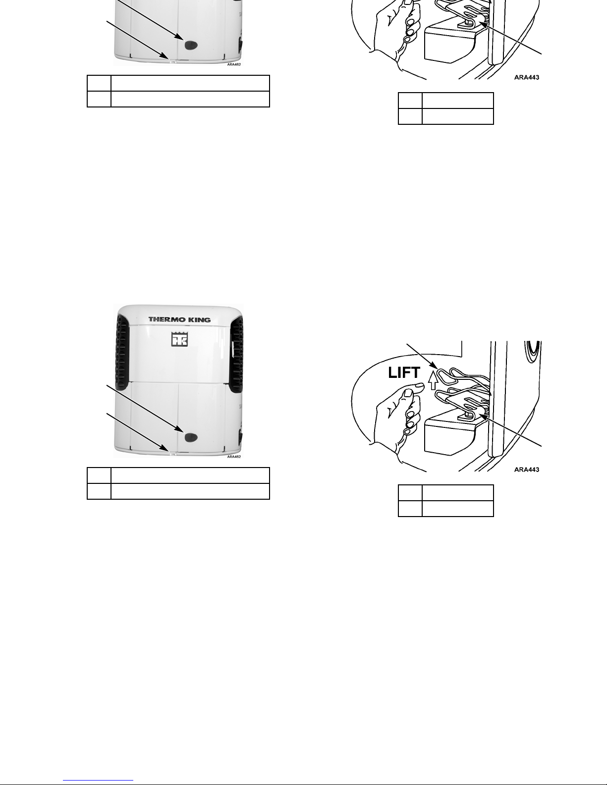
Opening the Front Doors
Pull the door latch handle to open the door and access the
engine compartment.
Opening the Secondary Door Latch
These units are also equipped with a secondary door latch. A
secondary door latch nameplate is located below the front
doors. After opening the door latch, reach between the front
doors and lift the spring latch over the spring catch while
opening the door.
1. Door Latch
2. Secondary Door Latch Nameplate
Figure 9: Door Latch Location
1
2
1. Spring Latch
2. Spring Catch
Figure 10: Opening Secondary Door Latch
1
2
Unit Description
29
Opening the Front Doors
Pull the door latch handle to open the door and access the
engine compartment.
Opening the Secondary Door Latch
These units are also equipped with a secondary door latch. A
secondary door latch nameplate is located below the front
doors. After opening the door latch, reach between the front
doors and lift the spring latch over the spring catch while
opening the door.
1. Door Latch
2. Secondary Door Latch Nameplate
Figure 9: Door Latch Location
1
2
1. Spring Latch
2. Spring Catch
Figure 10: Opening Secondary Door Latch
1
2
Page 31

Unit Description
30
Closing the Front Doors
Slam the door to close it. Do not push the door closed while
holding the door latch handle open or the door will not close
properly.
Unit Description
30
Closing the Front Doors
Slam the door to close it. Do not push the door closed while
holding the door latch handle open or the door will not close
properly.
Page 32

Unit Description
31
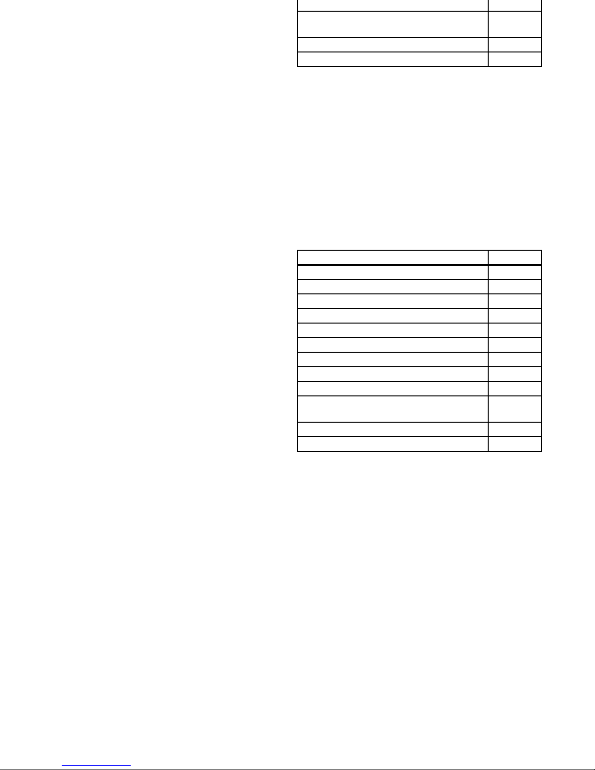
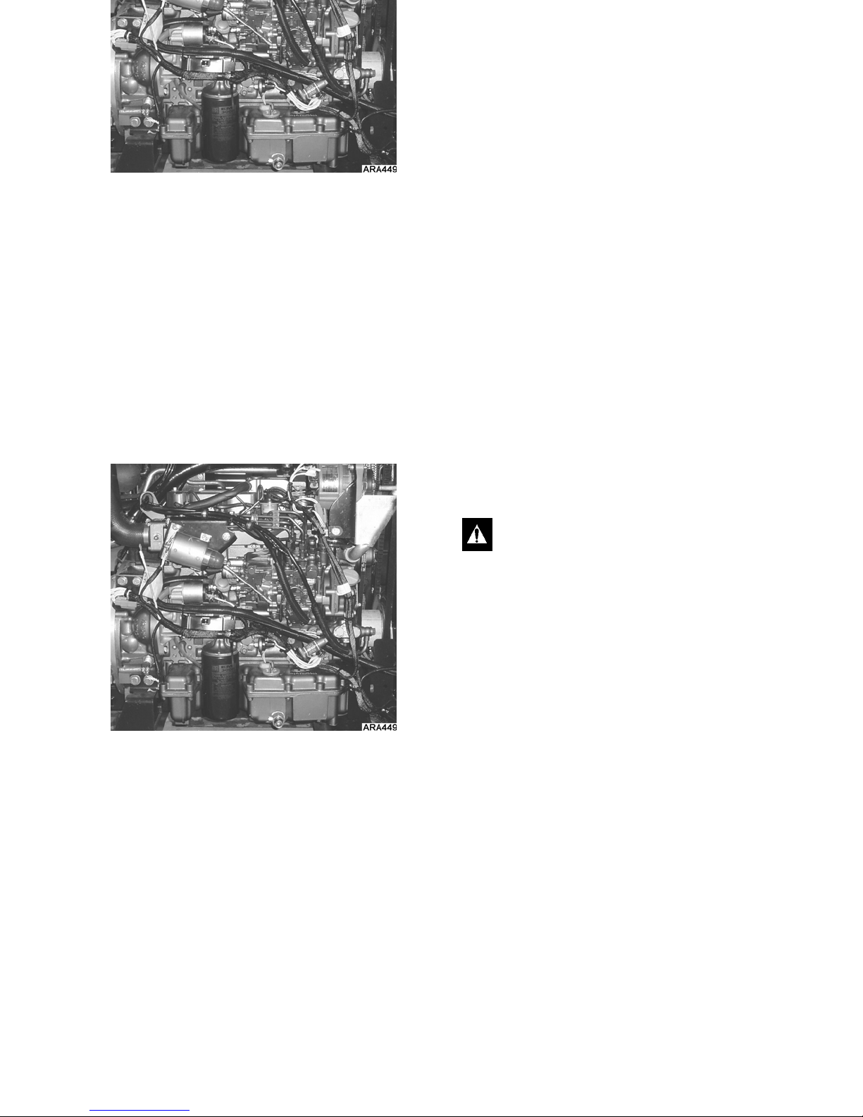
Engine Compartment Components
The following maintenance items can be checked visually.
Air Filter Restriction Indicator: The air filter restriction
indicator is attached to the engine intake manifold. When the
diaphragm indicates 25, service the air filter. Press the button
on the top of the restriction indicator to reset after servicing the
air cleaner.
Compressor Oil Sight Glass: Use this sight glass to check
the compressor oil level. Check the compressor oil when there
is evidence of oil loss (leaks). Refer to the unit Maintenance
Manual for the correct procedure.
Engine Oil Dipstick: Use the engine oil dipstick to check
the engine oil level.
1. Air Filter Restriction Indicator
2. Receiver Tank Sight Glass
3. Engine Oil Dipstick
4. Compressor Oil Sight Glass
Figure 11: Engine Compartment
21
34
WARNING: The unit can start at any time without
warning. Place the On/Off switch in the Off position
before inspecting any part of the unit.
CAUTION: Make sure the engi ne is turned of f before
attempting to check the engine oil.
Unit Description
31
Engine Compartment Components
The following maintenance items can be checked visually.
Air Filter Restriction Indicator: The air filter restriction
indicator is attached to the engine intake manifold. When the
diaphragm indicates 25, service the air filter. Press the button
on the top of the restriction indicator to reset after servicing the
air cleaner.
Compressor Oil Sight Glass: Use this sight glass to check
the compressor oil level. Check the compressor oil when there
is evidence of oil loss (leaks). Refer to the unit Maintenance
Manual for the correct procedure.
Engine Oil Dipstick: Use the engine oil dipstick to check
the engine oil level.
1. Air Filter Restriction Indicator
2. Receiver Tank Sight Glass
3. Engine Oil Dipstick
4. Compressor Oil Sight Glass
Figure 11: Engine Compartment
21
34
WARNING: The unit can start at any time without
warning. Place the On/Off switch in the Off position
before inspecting any part of the unit.
CAUTION: Make sure the engi ne is turned of f before
attempting to check the engine oil.
Page 33

Unit Description
32
Receiver Tank Sight Glass: This sight glass indicates the
level of refrigerant in the receiver tank.
Operate the unit in high speed cool for approximately 15
minutes to stabilize operating conditions and temperature
before attempting to check the refrigerant.
NOTE: If the ball floats, there is sufficient refrigerant in the
unit for that load at that particular trailer temperat ure. This
test does not determine if the unit contains a full charge or an
overcharge of refrigerant.
Unit Protection Devices
Fuse Link (Current Limiter): The fuse link is located in the
positive battery cable. The fuse link protects the electric
system from a short. If the fuse link burns out, replace it by
replacing the positive battery cable.
High Pressure Cutout Switch: The high pressur e cutout
switch (HPCO) is located on the compressor discharge
manifold. If the compressor discharge pressure becomes
excessive, the switch opens the circuit to the run relay to stop
the unit. The microprocessor will record Alarm Code 10.
High Pressure Relief Valve: This valve is designed to
relieve excessive pressure in the refrigeration system. It is
located on the receiver tank. If the high pressure relief valve
opens, much of the refrigerant will be lost. Take the unit to a
Thermo King dealer if this occurs.
Low Oil Level Switch: The low oil level switch closes if the
oil drops below an acceptable level. If it stays closed for a
specified time, the microprocessor shuts the unit down and
records Alarm Code 66.
Low Oil Pressure Switch: The low oil pressure switch
closes if the oil pressure drops below an acceptable level. If it
stays closed for a specified time, the microprocessor shuts the
unit down and records alarm code 19.
Preheat Buzzer: The preheat buzzer sounds when the
controller energizes the preheat relay. This warns anyone near
the unit that the controller is about to start the engine.
Page 34

Unit Description
33
Fuses: A number of fuses, located on the relay boar d, p rotect
various circuits and components. Not all of the fused circuits
and components are used in this system. The relay board (see
Figure 12 on page 34) is located inside the control box. Refer
to TK 53687 the TG-VIc Diagnostic Manual for more
information about the fuses.
Fuse Size Function
F1 2A High Speed Relay
F2 2A Defrost Relay
F3 15A Damper Solenoid/Motor
F4 2A Run Relay
F5 2A Hot Gas Solenoid
F6 2A Pilot Solenoid
F7 2A Starter Relay
F8 2A Preheat Relay
F9 40A #2 Circuit
F10 2A Cool Light/Damper Motor Heater
F11 2A VHN (Ammeter Shunt)
F12 2A Data Logger
F13 2A VHP (Ammeter Shunt)
F14 2A High Speed Light
F15
None2ANo Fuse - All Thermo King and Bosch
Alternators
2A Fuse - All Prestolite Alternators
F16 2A Electric Motor Contactor
F17 2A Defrost Light
F18 15A High Speed Solenoid
F21 15A #8F Circuit
F22 2A Electric Heater Contactor
F25 2A Cycle-Sentry Light
F26 2A Emergency Heat
F27 2A Spare Fuse
F28 15A Spare Fuse
F29 30A Spare Fuse
F30 40A Spare Fuse
Fuse Size Function
Page 35

Unit Description
34
Figure 12: Relay Board
F31 2A Modulation
F32 2A Remote Lights
F33 2A Oil Level Switch/ Door Switch
F34 2A Emergency Run
F35 2A Pilot Solenoid
F36 30A Main Power Fuse
F37 30A Main Power Fuse
Fuse Size Function
AJA106
9
Unit Description
34
Figure 12: Relay Board
F31 2A Modulation
F32 2A Remote Lights
F33 2A Oil Level Switch/ Door Switch
F34 2A Emergency Run
F35 2A Pilot Solenoid
F36 30A Main Power Fuse
F37 30A Main Power Fuse
Fuse Size Function
AJA106
9
Page 36

001 35
TG-VI Controller Description
TG-VI Overview
This unit is controlled by a ThermoGuard TG-VI
microprocessor. The TG-VI control panel consists of a display
screen and a keypad. The TG-VI control panel is shown in
Figure 13. This display shows all possible icons and characters.
Not all icons and characters will be displayed at the same time
in normal operation.
Unit operation is as simple as turning it on and entering a
setpoint. You can also:
• Initiate a manual defrost cycle
• Change the thermostat setpoint
• Change operating modes
• Check gauges, hourmeters, and alarm codes
• Run a unit self check.
Several other functions are also available. This chapter
describes the TG-VI control panel. For operating procedures,
see “Unit Operation” in this manual.
1. Display Screen
2. Keypad
Figure 13: TG-VI Control Panel With all Possible Icons
and Characters Displayed
ANA03
1
2
Page 37

TG-VI Controller Description
36
IMPORTANT: To prevent damage to the controller, always
push the controller access door firmly closed.
Display Screen
The display screen indicates operating status , inclu di ng
temperature, setpoint, mode, alarm codes, and other
information depending on the unit status. The display consists
of an upper and lower display in the center and icons around
the edges. The display shown here is displaying all possible
icons and characters. Not all icons and characters will be
displayed at the same time in normal operation.
The default display is called the Standard Display. See “Figure
16: Standard Display,” on page 39. The upper and lower
displays, the icons, the Stan dard Display, and other di splay
screens are described later in this section.
1. Upper Display 6. Lower Display
2. CYCLE-SENTRY Icon 7. Defrost Icon
3. Alarm Icon 8. Heat Icon
4. Electric Icon 9. Cool Icon
5. Setpoint Icon
Figure 14: Display Screen With all Possible Icons and
Characters Displayed
ANA03
1
2
3
4
5
6
7
8
9
Page 38

TG-VI Controller Description
37
Upper and Lower Display
The center of the display screen has a five character row of
large digits called the upper display and a four character row of
small digits called the lower display.
The upper and lower displays show operating data for the
screen you are viewing.
An example of operating data would be return temperature
(upper display) and setpoint (lower display) on the Standard
Display screen. See “Figure 15: Upper and Lower Displays,”
on page 37.
1. Upper Display
2. Lower Display
Figure 15: Upper and Lower Displays
AJA1077
1
2
Page 39

TG-VI Controller Description
38
Display Icons
Lit icons indicate the operating modes of the unit and show if
alarm codes are present. They appear around th e left, rig ht, and
bottom edges of the display, and are listed here in that order.
NOTE: Not all units are equipped with all functions.
Optional functions are noted. However, all icons light up
when the unit is powered on, regardless of whether the unit
has that function.
Cool Icon: Indicates that the unit is cooling.
Heat Icon: Indicates that the unit is heating.
Defrost Icon: Indicates that the unit is
defrosting.
CYCLE-SENTRY Icon: Indicates that the
unit is in CYCLE-SENTRY mode. This
feature may be optional on some units.
Alarm Icon: Indicates that one or more
alarm conditions are present.
Setpoint Icon: Indicates that the lower
display is the setpoint temperature.
Electric Standby Icon: Indicates that the
unit is running in electric standby mode.
Model 50 unit only.
Page 40

TG-VI Controller Description
39
Standard Display
The Standard Display is the default display screen showing
setpoint temperature and return air temperature. See “Figure
16: Standard D isplay,” on page 39.
On the Standard Display screen:
• The upper display shows the return air temperature in
Fahrenheit or Celsius depending on the unit’s
programming.
• The lower display shows the setpoint te mperature.
• The setpoint icon shows to the right of the lower display,
indicating that the lower display shown is the setpoint.
• The cool icon is displayed in the upper left corner of the
display.
• The CYCLE-SENTRY icon will also show if the unit is in
CYCLE-SENTRY.
1. CYCLE-SENTRY Icon
2. Setpoint Icon
3. Setpoint Temperature (Lower Display)
4. Cool Icon
5. Return Air Temperature (Upper Display)
Figure 16: Standard Display
AJA1077
5
3
2
1
4
Page 41

TG-VI Controller Description
40
Keypad
This section describes the keypad keys that control the
operating system.
1. S
ELECT Key 4. ENTER Key
2. U
P Key 5. TK LOGO Key
3. D
OWN Key
Figure 17: Ke ypad
ANA03
1
2
3
4
5
SELECT Key: Scrolls through the following
screens in the Standard Display mode:
[Pnt]: Print latest trip report. Displays only if
DAS is connected and Print Shortcut is
enabled.
[Alr]: Alarm codes, if any.
[DEF]: Defrost prompt.
[CYCLS]: CYCLE-SENTRY mode. Upper
display shows [C YCLS], lo wer displ ay show s
[YES] if on, [no] if off.
[dIS]: Discharge air temperature.
[tLH]: Total unit hours.
[EnH]: Diesel engine hours.
Hr4]: : Hourmeter 4 hours. Displays only if
hourmeter 4 is enabled.
Hr5]: : Hourmeter 5 hours. Displays only if
hourmeter 5 is enabled.
Page 42

TG-VI Controller Description
41
NOTE: If a DAS is installed, the unit must be on for
approximately 15 seconds with no keypad keys pressed for the
microprocessor to confirm the presence of the DAS.
S
ELECT Key (Continued)
[Hr6]: : Hourmeter 6 hours. Displays only if
hourmeter 6 is enabled.
[oIL]: Engine oil pressure.
[EnT]: Engine coolant temp.
[rPn]: Engine revolutions per minute.
[bAt]: Battery voltage.
[coL]: Coil temperature.
[dS1]-[dS6]: Up to six DAS sensors.
Displays only if DAS is connected.
[dFI]: Defrost interval in range.
[dFn]: Defrost interval not in range
[ddr]: Defrost duration.
UP Key: On the Standard Display screen, it
increases the setpoint. On other screens, it
changes the displayed prompt or other setting.
D
OWN Key: On the Standard Display screen,
it decreases the setpoint. On other screens, it
changes the displayed prompt or other setting.
E
NTER Key: Enters new temperature
setpoints and initiates or enters other settings.
TK L
OGO Key: Initiates unit self check and
displays software revision. Also used to print
a trip report and initiate a start of trip on units
equipped with a DAS.
Page 43

TG-VI Controller Description
42
TG-VI Controller Description
42
Page 44

43
Remote Status Light (Optional)
The Remote Status Light mounts on the cargo box for easy
viewing of the unit’s mode. The remote light indicates
operating status as follows:
Green status light: Illuminates the “T” portion of the TK
logo when the unit is functioning properly with no alarm
codes.
Amber status light: Illuminates the “K” portion of the TK
logo when the unit has a check alarm code, but is still
functioning properly. Check the unit as soon as possible to
correct the alarm condition.
Flashing status lights: The “T” (in green) and the “K” (in
amber) are illuminated and blinking when the unit has a
shutdown alarm code and the load integrity is at risk. Correct
the alarm condition immediately .
Figure 18: Remote Status Light
ANA23
Page 45

Remote Status Light (Optional)
44
Remote Status Light (Optional)
44
Page 46

45
Manual Pretrip Inspection
(Before Starting the Unit)
Pretrip inspections are an important part of a preventative
maintenance program designed to minimize operating
problems and breakdowns. Perform this pre-trip inspection
before every trip involving refrigerated cargo.
NOTE: Pretrip inspections are not intended to take the place
of regular maintenance inspections.
Fuel: Make sure the diesel fuel supply is adequate to
guarantee engine operation to the next check point. Allow for
maximum fuel consumption of one gallon per hour of engine
operation.
Engine Oil: Check the engine oil level. It should be at the
Full mark when the dipstick is threaded all the way into the oil
pan. Do not overfill.
Engine Coolant: Check the engine coolant level. The engine
coolant must have antifreeze protection to –30 F (–34 C).
Maintain a m i numum of 50% Ethylene Glycol based c oolant
and 50% water mixture. Do no t m ix so l ut ion any stronger than
68% Ethylene Glycol based coolant and 32% water for use in
extreme temperatures.
The engine is designed to operate on Ethylene Glycol based
coolant. This is the only recommended coolant type. Failure to
use the proper antifreeze mixture could cause plugging or
engine overheating. Do not mix brands , use wat er alone or mix
rust inhibitors.
Do not overfill the coolant.
CAUTION: Turn the engine off before checking the
engine oil level.
WARNING: Do not remove the expansion tank cap
while the coolant is hot.
Page 47

Manual Pretrip Inspection (Before Starting the Unit)
46
Keep the radiator clean and clear of debris by gently spraying
with water.
NOTE: Used Ethylene Glycol based coolant is a regulated
substance requir ing pr oper d isp osal. Ch eck for local disp osal
regulations. Do no t store in o pen contai ners. Keep away from
children and animals.
Battery: Make sure the battery terminals are tight and free of
corrosion. Electrolyte should be at the Full mark.
Belts: Make sure belts are in good condition and adjusted to
the proper tension. For more information about belt tension,
see the Specifications chapter.
Electrical: Check the electrical connections to make sure they
are securely fastened. Wires and terminals should be free of
corrosion, cracks, and moisture.
Structural: Visually inspect the unit for leaks, loose or
broken parts, and other damage.
Damper: Make sure the damper in the evaporator air outlets
move freely, with no sticking or binding.
Coils: Make sure the condenser and evaporator coils are clean
and free of debris.
Cargo Box: Check the interior and exterior of the trailer for
damage. Any damage to the walls or insulation must be
repaired.
Defrost Drains: Check the defrost drain hoses and fittings to
make sure they are open.
Doors: Make sure that the doors and weather seals are in good
condition. The doors should latch securely and the weather
seals should fit tightly.
IMPORTANT: To prevent damage to the controller, always
push the controller access door firmly closed.
CAUTION: If air is suspected to be trapped in the
system, it must be bled out. If the engine runs with air
trapped in the block, the engine may be damaged.
Page 48

47
Unit Operation with TG-VI Controller
Figure 19: TG-VI Microprocessor Controller
Thermo King has applied the latest advances in computer
technology to develo p a device that controls temperature and
unit functioning, and displays operating information quickly
and accurately.
There is nothing complicated about learning to operate the
TG-VI Microprocessor Controller, but you will find that a few
minutes studying the contents of this manual will be time well
spent.
This manual is published for informational purposes only and
the information furnished herein should not be considered as
all-inclusive or meant to cover all contingencies.
The following are general instructions for operating the TG-VI
Microprocessor Controller . It is recommended that you become
completely familiar with its operation before attempting to
start or operate the unit.
ANA03
Page 49

Unit Operation with TG-VI Controller
48
Control Panel
T wo sets o f controls ar e used to operate a unit that has a TG-VI
Microprocessor Controller. The Microprocessor control panel
contains the Display Screen (2) and Keypad (3) used to con trol
microprocessor operations.
Basic operation of the unit is controlled with the On/Off
switch (6) located on the Switch Panel.
On/Off Switch
The On/Off switch energizes the electrical control system for
the unit. In the On position, the unit will operate under the
control of the microprocessor. In the Off position, the electric
control system is de-energized and the unit will not operate.
WARNING: Do not operate the unit until you are
completely familiar with the location and fun ction of
each control.
WARNING: When the On/Off switch is in the On
position, the unit may start at any time without prior
warning.
1. Control Panel 4. Computer Port (Optional)
2. Display 5. Printer Port (Optional)
3. Keypad 6. On/Off Switch
Figure 20: Control and Switch Panels
ANA03
AJA1070
4
1
2
3
5
6
COMPUTER PRINTER
Page 50

Unit Operation with TG-VI Controller
49
Starting the Diesel Engine
Turn the On/Off switch to the On position. If no key is pressed,
the engine will automatically preheat and start in about 10
seconds. If a key is pressed (to change setpoint or view display
screens), the engine will automatically preheat and start about
10 seconds after the last key is pressed.
If the unit is in CYCLE-SENTRY mode and cooling, heating
or defrosting is required, the engine will automatically preheat
and start.
WARNING: When the On/Off switch is in the On
position, the unit may start at any time without prior
warning.
WARNING: Never use starting fluid.
Page 51

Unit Operation with TG-VI Controller
50
Starting the Unit with a Unit Self
Check Test
This procedure is used for a complete check of the trailer, unit,
and unit control circuits. It should be used when first starting
the unit for a trip before the cargo is loaded.
1. Perform a Pretrip Inspection. See the manual Pretrip
Inspection in the previous chapter.
2. This procedure is automatic and can be performed on the
way to the loading area or while waiting to load.
3. Place the On/Off switch in the On position.
4. Clear any alarms.
5. Press and hold the TK key for at least 3 seconds. USC
(Unit Self Check) will appear on the display.
6. Press the E
NTER key while USC is displayed.
7. Lod (load) will appear on the display and the Unit Self
Check will start.
1. TK Logo Key
2. Enter Key
Figure 21: Unit Self Check
AMA61
1
2
Page 52

Unit Operation with TG-VI Controller
51
8. If any alarms were not cleared before starting the Unit Self
Check, they will be displayed at this time. They can be
cleared by pressing the E
NTER key.
9. The controller will now automatically preheat and start the
diesel engine.
10. All segments of the display will be lighted at the same
time.
11. All programmable settings will be sequentially displayed.
These settings may be verified by the operator if
necessary.
12. The diesel engine RPM is checked in both high and low
speed.
13. The operation of the defrost damper is checked.
14. The ability of the unit to cool in low speed is checked.
15. The ability of the unit to heat is checked.
16. A second low speed cooling capacity check is performed
to insure that the unit can switch from cool to heat and
back to cool.
17. At the completion of the Unit Self Check, the check results
will appear on the display. They will remain until any key
on the controller is pressed. Check results are shown as
either PASS, CHEC or FAIL:
[PASS]—The unit is running and no alarms have been
recorded. The unit has passed the USC.
[CHEC]—T he unit is run ning but Check Alarms ha ve
been recorded.
[FAIL]—The unit has shut down. View and correct any
alarms. See “Figure 29: Alarm Symbol Location,” on
page 61.
Page 53

Unit Operation with TG-VI Controller
52
Displaying Operating Data
During Normal Operation
During normal operation, the standard display appears on the
screen. Return air temperature is displayed in the upper
readout, and the setpoint is displayed in the lower readout. In
this example, the return air temperature is 50.8 F and the
setpoint temperature is 35 F .
NOTE: If the unit is turned off by the optional remote
control, the display will read [Standby].
NOTE: The TG-VI can be programmed by a service
technician to display the setpoint to a tenth of a degree.
Press the S
ELECT key to display the prompt and display
screens. See “S
ELECT Key” on page 40 for list of these screens.
1. Select Key
Figure 22: Standard Display
AJA107
7
1
Page 54

Unit Operation with TG-VI Controller
53
Changing the Setpoint
The setpoint temperature of the Thermo King unit can be
quickly and easily changed.
1. With the standard display on the screen, press the U
P or
D
OWN key until the setpoint is at the desired temperature
setting.
Press and release either key repeatedly to cause the
temperature to change by 1 (or 0.1 degrees if programmed
to do so).
Hold either key down to cause the temperature to scroll
automatically. The longer the key is depressed, the faster
the scrolling speed.
2. Press and release the E
NTER key within 10 seconds to
enter the new setpoint into memory.
The display will briefly show Lod (load) in the lower
readout.The new setpoint will appear on the display. The unit
now operates with the new setpoint.
CAUTION: Make sure the ENTER key was pressed in
the first 10 seconds, or the original setpoint will
return to the screen and control the unit.
1. Up Key 3. Setpoint
2. Down Key 4. Enter Key
Figure 23: Changing the Setpoint
AJA1077
1
3
4
2
Page 55

Unit Operation with TG-VI Controller
54
Selection of Operating Modes
The Thermo King CYCLE-SENTRY system is designed to
save refrigeration fuel costs. The savings vary with the
commodity, ambient temperatures and trailer insulation.
However, not all temperature controlled products can be
properly transported using CYCLE-SENTRY operation.
Certain highly sensitive products normally require continuous
air circulation. Use the following guidelines to select the
proper operating mode to protect the commodity you are
transporting.
Examples of products normally acceptable for
CYCLE-SENTRY Operation:
• Frozen foods (in adequately insulated trailers)
• Boxed or processed meats
•Poultry
•Fish
• Dairy products
• Candy
• Chemicals
• Film
• All non-edible products.
Examples of products normally requiring Continuous Run
Operation for air flow:
• Fresh fruits and vegetables, especially asparagus,
bananas, broccoli, carrots, citrus, green peas, lettuce,
peaches, spinach, strawberries, sweet corn, etc.
• Non-processed meat products (unless pre-cooled to
recommended temperature)
• Fresh flowers and foliage.
The above listings are not all inclusive. Consult your grower or
shipper if you have any questions about the operating mode
selection of your type of load.
Page 56

Unit Operation with TG-VI Controller
55
Selecting CYCLE-SENTRY or
Continuous Mode
NOTE: The CYCLE-SENTRY icon will appear when the
CYCLE-SENTRY mode is selected and the O
N/OFF switch is
in the O
N position.
Continuous Mode: When Continuous mode is selected, the
unit will run continuously to maintain the setpoint and provide
constant airflow.
CYCLE-SENTRY Mode: : When the CYCLE-SENTRY
Mode is selected, the unit starts and stops automatically as
required to maintain the setpoint and to keep the engine warm
and the battery charged.
1. The unit must be turned on. Clear all alarms.
2. Press the S
ELECT key (cycling arrows) until the display
shows CYCLS and YES or NO.
3. Press the U
P or DOWN keys to choose YES or NO. YES
operates the unit in CYCLE-SENTRY. NO operates the
unit in Continuous Run.
4. Press the E
NTER key (equals sign) when the desired mode
is shown in the display.
NOTE: The E
NTER key must be pressed within 10 seconds to
load the new mode.
The display will briefly show Lod (load) and then the new
mode will appear.
1. Select Key 3. Down Key
2. Up Key
Figure 24: Selecting CYCLE-SENTRY
or Continuous Mode
ANA11
1
3
2
Page 57

Unit Operation with TG-VI Controller
56
Initiating a Manual Defrost Cycle
1. The unit must be running in Continuous or
CYCLE-SENTRY mode or be in CYCLE-SENTRY Null
mode and the coil temperature must be below 45 F (7 C).
2. Press the S
ELECT key until the dEF (defrost ) prompt
appears in the display.
3. Press the E
NTER key to enter a Defrost cycle. The display
will briefly show Lod (load). The unit will then enter a
Defrost cycle. The Defrost cycle will terminate
automatically.
NOTE: The E
NTER key must be pressed to enter a Defrost
cycle. The display will return to the Standard Display in
about 10 seconds and the defrost mode will not be entered
unless the E
NTER key is pressed.
1. Select Key 2. Enter Key
Figure 25: Initiating a Manual Defrost Cycle
AMA60
1
2
Page 58

Unit Operation with TG-VI Controller
57
Checking Software Revision
There are currently several different software revisions in use.
This information may be requested in the event that service is
required. To determine the software revision installed in your
unit, perform the following steps.
1. Place the On/Off switch in the ON position.
2. Press and hold the TK L
OGO key for at least three seconds.
The Unit Self Check [USC] prompt screen will appear.
3. Press the S
ELECT key (cycling arrows) until rEU
(revision) appears in the lower part of the display.
The number shown in the upper part of the display is the
software revision number.
1. Select Key 2. TK Logo Key
Figure 26: Checking Software Revision
ARA914
1
2
Page 59

Unit Operation with TG-VI Controller
58
Printing a Trip Report
This procedure is only available on units equipped with an
optional DAS datalogger. It prints the current DAS record
directly to an handheld printer. Only data from the directly
connected DAS sensors can be printed. Graphs are not
available with a handheld printer.
1. Connect the printer to the Printer Port on the front of
control panel.
2. Place the On/Off switch in the On position. The standard
display should appear on the screen. Wait for 15 seconds
before pressing any keys to allow the microprocessor to
confirm the presence of the DAS.
NOTE: If the Print Shortcut is enabled, pressing the
S
ELECT key at the standard display will take you directly
to the print screen.
3. Press and hold the TK L
OGO key for at least three seconds.
The Unit Self Check [USC] prompt screen will appear.
4. Press the S
ELECT key (cycling arrows) until Pnt (print)
appears in the lower part of the display.
1. Select Key 2. TK Logo Key
3. Printer Port
Figure 27: Printing a Trip Report
COMPUTER PRINTER
ARA915
1
2
3
Page 60

Unit Operation with TG-VI Controller
59
5. Press the ENTER key. The display will briefly show Lod
(load) and the printing process will begin.
6. Place the On/Off switch in the Off position to stop
printing.
NOTE: If printing is initiated without a printer connected, or
if the printer cable is not connected properly, printing will be
aborted after 30 seconds and the standard display will appear.
Page 61

Unit Operation with TG-VI Controller
60
Initiating a Start of Trip
This procedure is only available on units equipped with an
optional DAS datalogger. A “Start Of Trip” places a marker in
the datalogger memory. It is typically initiated when the cargo
is being loaded. The S tart Of Trip marker then shows when the
trip started in the data that is downloaded or printed from the
DAS datalogger. A Start Of Trip can be initiated through the
use of WinTrac datalogging software, or manually in the field.
The following procedure covers manual initiation. For more
information on datalogging, see the WinTrac User Manual
included with the WinTrac software. The WinTrac User
Manual is also available on the Internet at
HTTP://WWW.BLUETREE.IE.
7. Place the On/Off switch in the On position. The standard
display should appear on the screen. Wait for 15 seconds
before pressing any keys to allow the microprocessor to
confirm the presence of the DAS.
8. Press and hold the TK L
OGO key for at least three seconds.
The Unit Self Check [USC] prompt screen will appear.
9. Press the S
ELECT key (cycling arrows) until Pnt (print)
appears in the lower part of the display.
10. Press the E
NTER key. The display will briefly show Lod
(load). A Start Of Trip Marker has been inserted.
If no keys are pressed for 30 seconds, the standard display will
automatically reappear on the display.
1. Select Key 2. TK Logo Key
Figure 28: Initiating a Start of Trip
ARA916
1
2
Page 62

Unit Operation with TG-VI Controller
61
Displaying and Clearing Alarm
Codes
For detailed alarm code information refer to the “Alarm
Codes” chapter in this manual.
NOTE: Alarms are indicated by the appearance of an alarm
symbol (exclamation point within a triangle) in the
upper-right on the screen. Check alarms and stored alarms
are indicated by a steady alarm s ymbol. Shut down alar ms are
indicated by a flashing alarm symbol.
1. The unit On/Off switch must b e On. If the alarm s ymbol is
displayed on the screen, press the S
ELECT key.
2. If more than one alarm is present, each will be displayed
for several seconds.
NOTE: Some of the codes will only be meaningful to an
authorized TK service technician. If you are unable to clear
an alarm code, carefully record the number of the code and
refer the matter to an authorized dealer.
NOTE: Do not reset the alarm system until all the alarm
codes have been recorded, the alarm information has been
checked.
1. Alarm Symbol 3. Select Key
2. Enter Key
Figure 29: Alarm Symbol Location
ANA12
3
2
1
Page 63

Unit Operation with TG-VI Controller
62
3. To reset the alarm system.
a. Press the S
ELECT KEY to display the alarm screen.
b. Press the E
NTER KEY to clear the alarm. Enter must be
pushed to clear each alarm if more than one alarm is
present
After all alarms are cleared, the alarm symbol will
disappear. After about ten seconds, the standard display
will appear on the screen.
NOTE: If the alarm condition is not corrected, alarms may
continue to appear.
Alarm code 74 requires an authorized service technician to
reprogram the TG-VI.
Page 64

63
Alarm Codes
Introduction
An alarm is generated when the microprocessor senses an
abnormal condition. Alarms direct an operator or service
technician to the source of a problem.
Multiple alarms can be present at one time. All generated
alarms will be stored in memory until cleared by the operator.
Document all alarm occurrences and report them to the service
technician.
NOTE: The chart on the following pages shows all possible
alarm codes for all possible applications. Not all codes will be
applicable to each individual unit.
Repair
The operator can repair certain faults, other faults can only be
repaired by your Thermo King Dealer . Refer to the table on the
following pages for the proper corrective action.
NOTE: Document all alarm faults and report them to the
service technician.
NOTE: Alarms with an asterisk (*) can exist with Alarm
Code 84. The alarm can clear automatically if the condition
does not reoccur.
NOTE: The corrective actions listed on the “Table of Alarm
Codes” are suggestions only. Always consult your company
for final decisions.
Page 65

Alarm Codes
64
Alarm Types
The three types of alarms are described below. They can occur
individually or with other alarms. More than one alarm can be
present at one time.
Stored Alarm: Indicates a condition exists that should be
investigated, but does not affect unit o peration. T he alarm icon
will appear for 30 seconds when the unit On/Off switch is
turned on, then it disappears.
Check Alarm: Notice to take corrective action before an
abnormal condition becomes severe. The alarm icon will
appear and remain on.
Shutdown Alarm: Indicates conditions that could damage
the unit. The unit will automatically shut down, the alarm icon
will appear, and the entire display will flash on and off.
NOTE: Alarms that occurred during a unit pre-trip or self
check will be preceded by a dash (-). Refer to the Alarm Type
column on the following chart.
NOTE: Some alarms are self-clearing. These alarms will
clear automatically when the operating condition causing the
alarm returns to normal.
Corrective Action
There are three levels of corrective action that can be taken
when an alarm condition occurs.
OK To Run: An alarm condition exists but does not affect
unit operation. Corrective action can occur at a later date.
Check As Specified: An alarm condition exists that could
affect unit operation. Follow directions in the Corrective
Action column on the following chart.
Take Immediate Action: An alarm condition exists that
will damage the unit or load. Take immediate action to correct
the problem.
NOTE: The corrective actions listed above and on the
following chart are suggestions only. Always consult your
company for final decisions.
Page 66

Alarm Codes
65
Alarm Code 84 (Restart Null)
Alarm Code 84 is a temporary abnormal condition resulting
from other alarms. The unit shuts down for approximately 15
minutes. The unit will restart after approximately 15 minutes,
or after the condition has reset, and in most cases the other
alarm(s) will have been cleared. If after 3 attempts, the
condition continues to occur, the alarm that caused the
shutdown will appear on the display and the unit will shut
down until the alarm is cleared. Code 84 will automatically
clear after the final attempt at restarting has occurred.
Alarm Code 85
(Forced Unit Operation)
Alarm Code 85 is also a temporary abnormal condition
resulting from other alarm(s). The unit goes into an abnormal
mode which allows the unit to continue to run without shutting
down, the unit may however run with reduced capacity. When
the alarm that caused 85 is no longer active, Alarm Code 85
will be reset.
Page 67

Alarm Codes
66
Table of Alarm Codes
*Alarms with an asterisk (*) can exist with Ala rm Code 84. The alarm can clear automatically if condition does no t reoccur.
NOTE: Not all alarm codes are available with all microprocessor controllers or all revisions of software.
Code Description Corrective Action
Level Of
Action
Ok To
Run
Check
Shut
Down
00 No Fault None required. X
01 Microprocessor Power Up Reset Will not affect unit operation, data log only - clear alarm. X
02 Evaporator Coil Sensor Monitor box temp, repair as required. X
03 Return Air Sensor
Unit controls on discharge air sensor, monitor box temp,
repair as required.
X
04 Discharge Air Sensor
Unit controls on return air sensor, monitor box temp, repair
as required.
X
05 Ambient Air Sensor Unit operating with reduced features, repair as required. X
06 Engine Water Temp Sensor Unit operating with reduced features, repair as required. X
07 Engine RPM Sensor Unit operating with reduced features, repair as required. X
Page 68

Alarm Codes
67
08 Remote Return Air Sensor
Remote zone controls on coil sensor, monitor box temp,
repair as required.
X
09* High Evaporator Temperature Unit shut down to prevent damage, repair immediately. X
10*
High Discharge Pressu re or
Temp
Unit shut down to prevent damage, clear and retry, if
reoccurs repair immediately.
X
11
Unit Controlling on Alternate
Sensor
Secondary alarm related to Alarm Code 3 or 4, monitor box
temp, repai r a s required.
X
12 Sensor Shutdown Unit shut down to prevent damage, repair immediately. X
13 Check Sensor Calibration
Monitor box temp with independent thermometer, repair as
required.
X
14 Defrost Terminated by Time Clear alarm, repair after delivery. X
Table of Alarm Codes
*Alarms with an asterisk (*) can exist with Ala rm Code 84. The alarm can clear automatically if condition does no t reoccur.
NOTE: Not all alarm codes are available with all microprocessor controllers or all revisions of software.
Code Description Corrective Action
Level Of
Action
Ok To
Run
Check
Shut
Down
Page 69

Alarm Codes
68
15
Glow Plug/Intake Air Heater
Check
Repair after delivery. X
16 Manual Start Not Completed
Engine was not manually started, clear alarm and manually
start engine.
X
17* Engine Failed to Crank Attempt to start in Continuous mode, repair as required. X
18* High Engine Water Temperature Check belts and coolant level, repair as required. X
19* Low Engine Oil Pressure
Check engine oil level, add oil as needed, repair as
required.
X
20* Engine Failed to Start
Check fuel level, attempt to start in Continuous mode, repair
as required.
X
21 Cooling Cycle Check Monitor box temp, repair as required. X
22 Heating Cycle Check Monitor box temp, repair as required. X
Table of Alarm Codes
*Alarms with an asterisk (*) can exist with Ala rm Code 84. The alarm can clear automatically if condition does no t reoccur.
NOTE: Not all alarm codes are available with all microprocessor controllers or all revisions of software.
Code Description Corrective Action
Level Of
Action
Ok To
Run
Check
Shut
Down
Page 70

Alarm Codes
69
23* Cooling Cycle Fault Unit shut down to prevent damage, repair immediately. X
24* Heating Cycle Fault Unit shut down to prevent damage, repair immediately. X
25 Alternator Check Check alternator charging rate, repair immediately. X X
26 Check Refrigeration Capacity Monitor box temp, repair as required. X
27 Unassigned
28 Pretrip or Self-check Abort
Pretrip or self-check was terminated, check for other alarms
and repeat.
X
29 Damper Circuit
Unit or zone may not defrost, monitor box temp, repair as
required.
X
30 Damper Stuck Closed Damper is stuck closed, repair immediately. X
31 Oil Pressure Switch Oil pressure switch is not functioning. X
Table of Alarm Codes
*Alarms with an asterisk (*) can exist with Ala rm Code 84. The alarm can clear automatically if condition does no t reoccur.
NOTE: Not all alarm codes are available with all microprocessor controllers or all revisions of software.
Code Description Corrective Action
Level Of
Action
Ok To
Run
Check
Shut
Down
Page 71

Alarm Codes
70
32 Refrigeration Capacity Low Unit shut down to prevent damage, repair immediately. X
33 Check Engine RPM Check and note RPM, repair as required. X
34 Modulation Circuit
Check modulation circuit breaker or fuse, monitor box temp,
repair as required.
X
35 Run Relay Circuit Check run relay circuit, repair immediately. X
36*
Electric Motor Failed to
Run/Loose Belt
Check standby source of power and motor drive belt, repair
immediately.
X
37 Check Engine Water Level Check coolant level, add as needed. X
38
Phase Reversed /Overload
Tripped
Standby power phased wrong or motor overload tripped,
repair immediately. X
39 Water Valve Circuit
Unit operating with reduced heating, monitor box temp,
repair as required.
X
Table of Alarm Codes
*Alarms with an asterisk (*) can exist with Ala rm Code 84. The alarm can clear automatically if condition does no t reoccur.
NOTE: Not all alarm codes are available with all microprocessor controllers or all revisions of software.
Code Description Corrective Action
Level Of
Action
Ok To
Run
Check
Shut
Down
Page 72

Alarm Codes
71
40 High Speed Circuit
Check high speed operation, monitor box temp, repair as
required.
X
41 Engine Water Temp Check Check belts and coolant level, repair as required. X
42 Unit Forced to Low Speed
Temporary overheat condition, if condition persists repair as
required.
X
43 Unit Forced to Low Speed Mod
Temporary overheat condition, if condition persists repair as
required.
X
44* Fuel System
Check fuel level in unit fuel tank, add fuel, purge fuel lines
and restart as required.
X
45 Hot Gas Circuit
Unit operating with reduced modulation control, repair as
required.
X
46 Air Flow Check Cargo may be restricting air flow, check load. X
Table of Alarm Codes
*Alarms with an asterisk (*) can exist with Ala rm Code 84. The alarm can clear automatically if condition does no t reoccur.
NOTE: Not all alarm codes are available with all microprocessor controllers or all revisions of software.
Code Description Corrective Action
Level Of
Action
Ok To
Run
Check
Shut
Down
Page 73

Alarm Codes
72
47 Remote Sensor Shutdown
Multi-temp zone sensor failed, zone shut down, monitor
temp and repair as required.
X
48 Check Belts or Clutch Drive clutch or belts slipping, repair immediately X
49 RF Tag Communications Error
Data Tag disconnected or inoperative, affects data tag only,
repair as required.
X
50 Reset Clock
Unit will operate normally, set date and time to clear alarm.
(see the “Unit Operation” chapter for procedures).
X
51 Shutdown Circuit Secondary protection circuit failed, repair as required. X
52 Heat Circuit
May have no heat, monitor box temperature, repair as
required.
X
53 Economizer Valve Circuit
Unit operating with reduced heat performance, monitor box
temp, repai r a s required.
X
Table of Alarm Codes
*Alarms with an asterisk (*) can exist with Ala rm Code 84. The alarm can clear automatically if condition does no t reoccur.
NOTE: Not all alarm codes are available with all microprocessor controllers or all revisions of software.
Code Description Corrective Action
Level Of
Action
Ok To
Run
Check
Shut
Down
Page 74

Alarm Codes
73
54 Test Mode Time-out
A diagnostic mode timed out, does not affect unit
performance.
X
55 Check Engine Speeds
Engine speed out of spec, check RPM, monitor box temp,
repair as required.
X
56 Evap Fan Low Speed
Unit operating with no low speed evaporator fan, repair as
required (RC units only).
X
57 Evap Fan High Speed
Unit operating with no high speed evaporator fan, repair as
required (RC units only).
X
58 Cond Fan Low Speed
Unit operating with no low speed condenser fan, repair as
required (RC units only).
X
59 Cond Fan High Speed
Unit operating with no high speed condenser fan, repair as
required (RC units only).
X
Table of Alarm Codes
*Alarms with an asterisk (*) can exist with Ala rm Code 84. The alarm can clear automatically if condition does no t reoccur.
NOTE: Not all alarm codes are available with all microprocessor controllers or all revisions of software.
Code Description Corrective Action
Level Of
Action
Ok To
Run
Check
Shut
Down
Page 75

Alarm Codes
74
60 Boost Circuit
Unit operating without boost capacitors, repair as required
(RC units only).
X
61 Low Battery Volts Check charge rate and battery voltage, repair as required. X
62 Ammeter Out of Cal Range Ammeter inaccurate, repair as required. X
63* Engine Stopped Engine should be running, try restart, repair as required. X
64 Pretrip Reminder
Does not affect unit operation, perform Pretrip or Unit Self
Check to clear alarm.
X
65 Abnormal Temp Differential
If unit is shutdown, repair immediately. Otherwise, monitor
box temp and repair as required.
XX
66 Low Engine Oil Level Check engine oil level, add as needed. X
67 Liquid Line Solenoid Circuit
Unit operating with reduced performance, monitor box temp,
repair as required.
X
Table of Alarm Codes
*Alarms with an asterisk (*) can exist with Ala rm Code 84. The alarm can clear automatically if condition does no t reoccur.
NOTE: Not all alarm codes are available with all microprocessor controllers or all revisions of software.
Code Description Corrective Action
Level Of
Action
Ok To
Run
Check
Shut
Down
Page 76

Alarm Codes
75
68 µP Internal Fault Code Clear and retry, monitor box temp, repair as required. X
69 Remagnetization Circuit
Clear and retry, if alarm reoccurs or is shutdown repair as
required (RC units only).
X
70 Hourmeter Failure Will not affect unit operation, repair after delivery. X
71 Hourmeter 4 Exceeds Set Limit
Maintenance alarm dependent on customer selection, will
not affect unit operation.
X
72 Hourmeter 5 Exceeds Set Limit
Maintenance alarm dependent on customer selection, will
not affect unit operation.
X
73 Hourmeter 6 Exceeds Set Limit
Maintenance alarm dependent on customer selection, will
not affect unit operation. X
74 µP Reverted to Default Settings
Unit has reset, control parameters. May be inaccurate,
repair immediately.
X
Table of Alarm Codes
*Alarms with an asterisk (*) can exist with Ala rm Code 84. The alarm can clear automatically if condition does no t reoccur.
NOTE: Not all alarm codes are available with all microprocessor controllers or all revisions of software.
Code Description Corrective Action
Level Of
Action
Ok To
Run
Check
Shut
Down
Page 77

Alarm Codes
76
75 µP Internal Fault Code Controller may be defective, repair immediately. X
76 µP Internal Fault Code Controller may be defective, repair immediately. X
77 µP Internal Fault Code Controller may be defective, repair immediately. X
78 µP Internal Fault Code Controller may be defective, repair immediately. X
79 Data Log Overflow
Data logger missed logging one event, no action required,
clear alarm.
X
80 Compressor Temp Sensor Compressor protection reduced, repair as required. X
81 High Comp T emp Compressor operating above temp limits, repair as required. X
82 High Comp Temp Shutdown
Compressor shut down to prevent damage, repair
immediately.
X
83 Low Coolant Temp
Reduced heating capacity, monitor box temp and engine
temp, repai r a s required.
X
Table of Alarm Codes
*Alarms with an asterisk (*) can exist with Ala rm Code 84. The alarm can clear automatically if condition does no t reoccur.
NOTE: Not all alarm codes are available with all microprocessor controllers or all revisions of software.
Code Description Corrective Action
Level Of
Action
Ok To
Run
Check
Shut
Down
Page 78

Alarm Codes
77
84 Restart Null
Temporary shutdown resulting from other alarm codes.
Refer to detailed explanation at start of chapter.
X
85 Forced Unit Operation
Tempor ary for ce d operati on resu lti ng fro m other alar m
codes. Refer to detailed explanation at start of chapter.
X
86 Discharge Press Transducer
Unit operating with reduced performance, monitor box temp,
repair as required.
X
87 Sucti on Pres s Transducer
Unit operating with reduced performance, monitor box temp,
repair as required.
X
88 Unassigned
89 Electronic Throttling Valve Circuit
If Check Alarm, unit operating with reduced performance,
monitor box temp, repair as required. If Shutdown Alarm,
ETV or refrigeration system failure, repair immediately.
XX
Table of Alarm Codes
*Alarms with an asterisk (*) can exist with Ala rm Code 84. The alarm can clear automatically if condition does no t reoccur.
NOTE: Not all alarm codes are available with all microprocessor controllers or all revisions of software.
Code Description Corrective Action
Level Of
Action
Ok To
Run
Check
Shut
Down
Page 79

Alarm Codes
78
90-
92
Unassigned
93
Low Compressor Suction
Pressure
Suction pressure lower than expected for current conditions,
repair as required.
X
94 Loader Valve #1
Suction pressure drops less than specified when Loader
V alve #1 is energized during unit start up, repair as required.
X
95 Loader Valve #2
Suction pressure drops less than specified when Loader
V alve #2 is energized during unit start up, repair as required.
X
96 Low Fuel Level Check fuel level, add as needed. X
97 Unassigned
98 Check Fuel Level Sensor Low fuel level or defective fuel level sensor. X
Table of Alarm Codes
*Alarms with an asterisk (*) can exist with Ala rm Code 84. The alarm can clear automatically if condition does no t reoccur.
NOTE: Not all alarm codes are available with all microprocessor controllers or all revisions of software.
Code Description Corrective Action
Level Of
Action
Ok To
Run
Check
Shut
Down
Page 80

Alarm Codes
79
99 High Compressor Pressure Ratio
Compression ratio of discharge to suction pressure has
risen above specification, repair as required.
X
100-
104
Unassigned
105
Receiver Tank Press Solenoid
Circuit
Unit operating with reduced heat performance, monitor box
temp, repai r a s required.
X
106 Purge Valve Circuit
Unit operating with reduced heat performance, monitor box
temp, repai r a s required.
X
107 Condenser Inlet Solenoid Circuit
Unit operating with reduced performance, monitor box temp,
repair as required.
X
108 Door Open Timeout Door open for extended time, close door and clear alarm. X
Table of Alarm Codes
*Alarms with an asterisk (*) can exist with Ala rm Code 84. The alarm can clear automatically if condition does no t reoccur.
NOTE: Not all alarm codes are available with all microprocessor controllers or all revisions of software.
Code Description Corrective Action
Level Of
Action
Ok To
Run
Check
Shut
Down
Page 81

Alarm Codes
80
109 High Discharge Pressure/Sensor
High discharge press or defective discharge press sensor,
high speed prevented.
X
110 Suction Line Solenoid CIrcuit
Unit operating with reduced performance, monitor box temp,
repair as required.
X
111 Unit Not Configured Correctly Controller not set properly for unit type, repair immediately. X
112 Remote Fan Zone 2-3 Circuit Remote fan failure in indicated zone, repair as required. X
113 Electric Heat Circuit Electric heating problem, repair as required. X
114 Multiple Alarms, Can Not Run
Multiple problems prevent unit operation, check alarm
codes, repair immediately.
X
Table of Alarm Codes
*Alarms with an asterisk (*) can exist with Ala rm Code 84. The alarm can clear automatically if condition does no t reoccur.
NOTE: Not all alarm codes are available with all microprocessor controllers or all revisions of software.
Code Description Corrective Action
Level Of
Action
Ok To
Run
Check
Shut
Down
Page 82

Alarm Codes
81
115-
120
Unassigned
121 Liquid Injection Valve
Unit operating with reduced performance, monitor box temp,
repair as required.
X
Table of Alarm Codes
*Alarms with an asterisk (*) can exist with Ala rm Code 84. The alarm can clear automatically if condition does no t reoccur.
NOTE: Not all alarm codes are available with all microprocessor controllers or all revisions of software.
Code Description Corrective Action
Level Of
Action
Ok To
Run
Check
Shut
Down
Page 83

Alarm Codes
82
Alarm Codes
82
Page 84

001 83
Loading and Enroute Inspections
This chapter describes pre-loading, post loading, and enroute
inspection procedures. Thermo King refrigeration units are
designed to maintain the required product load temperature
during transit. Follow these recommended loading and enroute
procedures to help minimize temperature related problems.
Pre-Loading Inspection
1. Pre-cool products before loading. Note any variances on
the manifest.
2. Inspect door seals and vent doors for condition and a tight
seal with no air leakage.
3. Inspect the trailer inside and out. Look for:
• Damaged or loose trailer skin and insulation
• Damaged walls, air ducts, floor channels or “T”
flooring
• Clogged defrost drain tubes
• Blocked return air bulkhead
4. Verify that the setpoint temperature is correct for your
cargo. Pre-cool the trailer as required.
5. Push the microprocessor controller access door firmly
closed after setting temperature setpoint
6. Supervise product loading to ensure sufficient air space
around and through the load. Airflow around the cargo
must not be restricted.
NOTE: If the warehouse is not refrigerated, operate the
unit with doors closed until cargo is ready to be loaded.
Then turn off t he u nit , o pen ca rgo doors and load car go .
When cargo is loaded, close trailer doors and restart the
unit.
The unit can be operated with the cargo box doors open
if the truck is backed into a refrigerated warehouse and
the dock door seals fit tightly around the trailer.
CAUTION: Push the controller access door firmly
closed after each use. Damage can occur in transit if
the door is not properly closed.
Page 85

Loading and Enroute Inspections
84
Figure 30: Loading Considerations
ADZ30
6
8
9
1
2
5
4
7
1. Correct load height (trailers without chutes)
2. Tight doors and gaskets
3. Good air circulation around load
4. Proper cargo temperature (prior to load ing )
5. Interior/exterior walls and insulati on in goo d
condition
6. Clear defrost drains
7. Good outside air circulation
8. Unit inspection
9. Tight seals
3
Page 86

Loading and Enroute Inspections
85
Post-Loading Inspection
Post-loading inspections ensure the cargo has been loaded
properly. To perform a post-load inspection:
1. Inspect the evaporator outlets for blockage.
2. Turn the unit off before opening the cargo box doors to
maintain efficient operation.
NOTE: The unit can be operated with the cargo box
doors open if the truck is backed into a refrigerated
warehouse and the dock door seals fit tightly around the
trailer.
3. Perform a final check of the load temperature. If the load
is above or below temperature, make a final notation on
the manifest.
4. Close or supervise the closing of the cargo box doors.
Make sure they are securely locked.
5. Make sure the setpoint is at the temperature listed on the
manifest.
6. If the unit was stopped, restart using the correct starting
procedure. See the Operating Instruction chapter in this
manual.
7. Start a manual defrost cycle 30 minutes after loading. See
the Manual Defrost procedure in this manual.
8. Push the microprocessor controller access door firmly
closed.
CAUTION: Cargo must be pre-cooled to the proper
temperature before loading. The uni t is desig ned to
maintain temperature, not cool an above-temperature
load.
CAUTION: Push the controller access door firmly
closed after each use. Unit damage can occur in
transit if the door is not properly closed.
Page 87

Loading and Enroute Inspections
86
Enroute Inspections
Complete the following enroute inspection every four hours.
This will help minimize temperature related problems.
Inspection Procedure
1. Verify setpoint is correct.
2. Check the return air temperature reading. It should be
within the desired temperature range.
3. Initiate a manual defrost cycle after each enroute
inspection.
Inspection Troubleshooting
1. If a temperature reading is not within the desired
temperature range, refer to t he troubleshooting t able on the
following pages. Correct problem as required.
2. Repeat the Enroute Inspection every 30 minutes until the
compartment temperature is within the desired
temperature range. Stop the unit if the compartment
temperature is not within the desired temperature ran ge on
two consecutive 30 minute inspections, especially if the
compartment temperature appears to be moving away
from the setpoint.
3. Immediately contact the nearest Thermo King Service
Center or your company office.
4. Take all necessary steps to protect and maintain proper
load temperature.
CAUTION: Stop the unit if the comp artment
temperature remains higher than the desir e d
temperature range from the setpoint on two
consecutive 30 minute inspections. Contact the
nearest Thermo King Service Center or your
company office immediately . Take all necessary steps
to protect and maintain proper load temperature.
Page 88

Loading and Enroute Inspections
87
Inspection Troubleshooting
Problem Cause Remedy
A return air
temperature
reading is not
within desired
temperature
range of the
setpoint.
The unit has not
had time to cool
down to correct
temperature.
Refer to the load log history. Look for above temperature load records,
properly pre-cooled cargo compartment, length of time on road, etc. Correct
as required. Continue monitoring return air temperature until the reading is
within the desired temperature range of the setpoint.
The unit may have
a low refrigerant
charge.
Check the receiver tank sight glass for refrigerant level. If liquid is not
showing in the receiver tank sight glass, the refrigerant charge may be low.
A competent refrigeration technician is required to add refrigerant or repair
the system. Contact the nearest Thermo King dealer, authorized Service
Center, or call the Thermo King Cold Line for referral. Consult the Table of
Contents for Cold Line information.
The unit is in defrost
or has just
completed a defrost
cycle.
Monitor the return air temperature after the defrost cycle is completed to see
if the temperature returns to the desired temperature range of the setpoint.
The evaporator is
plugged with frost.
Initiate a manual defrost cycle. The defrost cycle will automatically terminate
when complete. Continue monitoring the return air temperature until the
reading is within the desired temperature range of the setpoint.
Page 89

Loading and Enroute Inspections
88
Improper air
circulation in the
cargo compartment.
Inspect the unit and cargo compartment to determine if the evaporator fan(s)
are working and properly circul ating the air. Poor air circulation may be due
to improper loading of the cargo, shifting of the load, or fan belt slippage.
Correct as required. Continue monitoring return air temperature until
problem is corrected.
The unit did not
start automatically.
Determine the cause for not starting. Correct as required. Continue
monitoring the return air temperature until the reading is within the desired
temperature range of the setpoint.
Problem Cause Remedy
Page 90

89
Jump Starting
If the battery in a unit is discharged or run down, the unit may
be jump started using jumper cables and another battery or
vehicle. Consider the following precautions and be careful
when jump starting a unit.
IMPORTANT: Make sure to use a 12-volt battery to jump
start the unit. If you are using a vehicle, make sure it has a
12-volt battery with a negative ground system. Do not use a
“hot shot” booster device or a 24-volt source.
Read and understand the following procedure completely
before connecting any jumper cables. Use good jumper cables
made with #2 gauge (or larger) cables.
1. Make sure the unit is turned of f. If you are u sing a vehicle,
make sure its ignition is also turned off.
2. Open the front doors on the unit. The battery is located to
the right of the engine.
3. Check the discharged battery to make sure it is not
damaged or frozen. Do not jump start a damaged or frozen
battery. Check the vent caps to make sure they are tight.
4. Identify the positive (+) and negative (–) battery terminals.
W A RNING : A ba tte ry ca n be da nge rou s. A batt ery
contains a flammable gas that can ignite or
explode. A battery stores enough electricity to burn
you if it discharges quickly. A battery contains
battery acid that can burn you. Always wear
goggles or safety glasses and personal protective
equipment when working with a battery. If you get
battery acid on you, immediately flush it with water
and get medical attention.
CAUTION: Unhook the semi tractor from the
trailer before using the tractor to jum p start the
unit on the trailer. The negative ground circuit is
complete when the tractor is hooked to the trailer.
This can cause dangerous sparks when the positive
connection is made at the battery.
Page 91

Jump Starting
90
5. Remove the red cover from the positive (+) battery
terminal on the unit’s battery.
CAUTION: Do not use a match or lighter as a
light near the battery. Use a flashlight . A flame or
a spark can ignite the gas in the battery and cause
it to explode.
1. Red Cover on Positive (+) Battery Terminal
Figure 31: Unit Battery
1
1. Positive (+) T erminal on Unit Battery
2. Positive (+) Terminal on Good Battery
3. Negative (–) Terminal on Good Battery
4. Starter Mounting Bolt on Unit Engine
Figure 32: Sequence for Connecting Jumper Cables
1
Unit
(Discharged)
12-Volt
Battery
Good
12-Volt
Battery
Unit
Engine
2
3
4
Page 92

Jump Starting
91
6. Connect the red positive (+) jumper cable to the positive
(+) battery terminal on the unit’s battery. Do not let the
other end of the jumper cable touch an ything that conducts
electricity.
7. Connect the other end of the red positive (+) jumper c able
to the positive (+) battery terminal on the good battery.
8. Connect the black negative (–) jumper cable to the
negative (–) battery terminal on the good battery. Do not
let the other end of the jumper cable touch anything that
conducts electricity.
9. Connect the black negative (–) jumper cable to the lower
starter mounting bolt on the unit’s engine.
CAUTION: Allowing the positive (+) jumper cable
to short can produce dangerous sparks.
1. Lower Starter Mounting Bolt
Figure 33: Unit Engine
1
Page 93

Jump Starting
92
10. If you are using a vehicle to jump start the unit, start the
vehicle and let it run for a few minutes. This will help
charge the discharged battery.
11. Turn the unit on and let it start automatically or start it
manually. If the unit will not crank or start, contact a
qualified technician.
NOTE: Some units with microprocessors will show an
alarm code and will not try to start until the battery
voltage is above 10 volts.
12. After the unit starts, remove the jumper cables in reverse
order: black negative (–) from the unit starter mounting
bolt, black negative (–) from the goo d battery, red positive
(+) from the good battery, and red positive (+) from the
unit battery (that was discharged).
CAUTION: Be careful around fans and belts.
Keep your hands away from moving parts when an
engine is running.
1. Starter Mounting Bolt on Unit Engine
2. Negative (–) Terminal on Good Battery
3. Positive (+) Terminal on Good Battery
4. Positive (+) T erminal on Unit Battery
Figure 34: Sequence for Disconnecting Jumper Cables
4
Unit
(Discharged)
12-Volt
Battery
Good
12-Volt
Battery
Unit
Engine
3
2
1
Page 94

93
Specifications
Engine
Engine TK486V (Tier 2)
Fuel Type No. 2 diesel fuel under normal conditions
No. 1 diesel fuel is acceptable cold weather fuel
Oil Capacity: Crankcase 13 quarts (12.3 liters)
Fill to full mark on dipstick
Oil Type API Classification CI-4 or better
Oil Viscosity 5 to 122 F (-15 to 50 C): SAE 15W-40
-13 to 104 F (-25 to 40 C): SAE 10W-40
-13 to 86 F (-25 to 30 C): SAE 10W-30
-22 to 32 F (-30 to 0 C): SAE 5W-30
Engine Oil Pressure The microprocessor will display OK if the oil pressure is within an
acceptable range and LOW if the oil pressure is below this range.
Low Oil Pressure Switch (Normally Closed) 17 ± 3 psi (117 ± 21 kPa)
Engine rpm: Low Speed Operation
High Speed Operation
1450 +
25 rpm
2200 ± 25 rpm
Page 95

Specifications
94
Engine Thermostat 160 F (71 C)
Engine Coolant Type ELC (Extended Life Coolant), which is red.
Use a 50/50 concentration of any of the following equivalents:
Chevron Dex-Cool
Texaco ELC
Havoline Dex-Cool®
Havoline XLC for Europe
Shell Dexcool®
Shell Rotella
Saturn/General Motors Dex-Co ol®
Caterpillar ELC
Detroit Diesel POWERCOOL® Plus
CAUTION: Do not add “GREEN” or “BLUE-GREEN”
conventional coolant to cooling systems using “RED”
Extended Life Coolant, except in an emergency. If conventional
coolant is added to Extended Life Coolant, the coolant must be
changed after 2 years instead of 5 years.
Coolant System Capacity 7.5 quarts (7.1 liters)
Radiator Cap Pressure 7 psi (48 kPa)
Drive Direct to compressor; belts to fans, alternator and water pump
Engine (Continued)
Page 96

Specifications
95
Belt Tension
Belt Tension No. on TK Gauge 204-427
Alternator Belt 61
Lower Fan Belt (Engine to Idler) 67
Upper Fan Belt (Fan to Idler) 74
NOTE: These are the field reset settings. Because it is sometimes difficult to use the TK Gauge 204-427 in the
field, adjust each belt to allow 1/2 inch (13mm) deflection at the center of the longest span.
Electrical Control System
Voltage 12.5 Vdc
Battery One, Group C31, 12 volt, (950 CCA recommended for operation
below -15 F [-26 C])
Battery Charging Alternator 12 V, 37 Amp (brush type)
Voltage Regulator Setting 13.8 to 14.2 Vdc at 77 F (25 C)
Fuses 2 to 40 Amp (see “Fuses” on page 33)
Page 97

Specifications
96
Refrigeration System
Compressor Thermo King X430L
Compressor Oil Charge 4.3 quarts (4.1 liters)
Compressor Oil Type Polyol Ester Type P/N 203-413
Refrigerant Charge - Type 13 lb (5.9 kg) - R404A
Heat/Defrost Method Hot gas
High Pressure Cutout Switch Opens 470 +7/-35 psi (3241 +48/-241 kPa)
Automatic Reset @ 375 ± 38 psi (2586 ± 262 kPa)
Page 98

97
Maintenance Inspection Schedule
A closely followed maintenance program will help to keep
your Thermo King unit in top operating condition. The
following general schedule is provided to assist in monitoring
that maintenance.
For more details, refer to the appropriate maintenance manual
and to the “Manual Pretrip Inspection” in this manual.
Pretrip
Every
1,500
Hours
Every
3,000
Hours*
Annual
4,500
Hours
Inspect/Service These Items
Engine
• Check fuel supply and engine oil level.
• Inspect belts for condition and proper tension (belt tension tool No. 204-427).
••••Check engine oil pressure hot, on high speed (should display “OK”).
••••Listen for unusual noises, vibrations, etc.
*3,000 hours or two years, whichever occurs first.
Page 99

Maintenance Inspection Schedule
98
Engine (Continued)
••• Check air cleaner restriction indicator (change when indicator reaches 25
in.). Replace EMI 3000 air cleaner element at 3,000 hours or two years
(whichever occurs first) if air cleaner restriction indicator has not reached 25
in. The EMI 3000 air cleaner element has a nameplate that reads “EMI
3000.”
••••Check engine coolant level and antifreeze protection (-30 F [-34 C]).
•••Drain water from fuel tank and check vent.
•••Inspect/clean fuel transfer pump inlet strainer (pre-filter).
•••Check and adjust engine speeds (high and low speed).
• Replace fuel filter/water separator.
• Change engine oil and oil filter (hot). Requires oil with API Rating CI-4 or
better.
• Check condition of engine mounts.
• Check condition of drive coupling bushings per Service Bulletin T&T 171.
Pretrip
Every
1,500
Hours
Every
3,000
Hours*
Annual
4,500
Hours
Inspect/Service These Items
*3,000 hours or two years, whichever occurs first.
Page 100

Maintenance Inspection Schedule
99
Engine (Continued)
— Change ELC (red) engine coolant every 5 years or 12,000 hours.
— Test fuel injection nozzles at least every 10,000 hours.
— Replace fuel return lines between fuel injection nozzles every 10,000 hours.
Electrical
••••Check damper door operation
(closes on defrost initiation, opens on defrost termination).
•••Inspect battery terminals and electrolyte level.
•••Inspect wire harness for damaged wires or connections.
• Inspect alternator wire connections for tightness.
Microprocessor
• Run Unit Self Check Test (see “Starting the Unit with a Unit Self Check Test”
on page 50).
Pretrip
Every
1,500
Hours
Every
3,000
Hours*
Annual
4,500
Hours
Inspect/Service These Items
*3,000 hours or two years, whichever occurs first.
 Loading...