

Thermo King MAGNUM, MAGNUM 20, MAGNUM SL, 098922, 098924 Maintenance Manual
...
Maintenance Manual
SB-210+
SB-210+
MAGNUM
Additional text information
Additional text information
to be placed here
to be placed here
TK 51122-4-MM (Rev. 6, 02/06)
TK 5XXXX-X-PL
TK 5XXXX-X-PL
MAGNUM
TK 51122-4-MM (Rev. 6, 02/06)
Copyright© 2004 Thermo King Corp., Minneapolis, MN, USA.
Printed in USA.

The maintenance information in this manual covers unit models:
Base Unit
MAGNUM 098922
MAGNUM 098924
MAGNUM SL 098934
MAGNUM SL 098935
MAGNUM 20 098916
For further information, refer to:
Parts Manuals
MAGNUM Parts List TK 51745
Operation, Diagnosis and Refrigeration Maintenance Manuals
Diagnosing Thermo King Container Refrigeration Systems TK 41166
Electrostatic Discharge (ESD) Training Guide TK 40282
Evacuation Station Operation and Field Application TK 40612
Tool Catalog TK 5955
The information in this manual is provided to assist owners, operators and service people in the proper
upkeep and maintenance of Thermo King units.
This manual is published strictly for informational purposes. The inf ormation so provided sho uld
not be considered as all-inclusive or covering all contingencies. Thermo King Corporation
should be consulted if further information is required.
Sale of product shown in this manual is subject to Thermo King’s terms and conditions.
This includes, but not limited to, the Thermo King Limited Express Warranty. Such terms
and conditions are available upon request. Thermo King’s warranty will not apply to any
equipment which has been “so repaired or altered outside the manufacturer’s plants as,
in the manufacturer’s judgment, to effect its stability.”
No warranties, express or implied, are made regarding the inf o rmation,
recommendations, and descriptions contained herein. This includes warranties of
fitness for a particular purpose or merchantability, or warranties arising from course of
dealing or usage of trade. The manufacturer is not responsible and will not be held liable
in contract or in tort (including negligence) for any special, indirect or consequential
damages. This includes injury or damage caused to vehicles, contents or persons, by
reason of the installation of any Thermo King product or its mechanical failure.
Recover Refrigerant
At Thermo King, we recognize the need to preserve the environment
and limit the potential harm to the ozone layer that can result from
allowing refrigerant to escape into the atmosphere.
We strictly adhere to a policy that promotes the recovery and limits
the loss of refrigerant into the atmosphere.
In addition, service personnel must be aware of Federal regulations
concerning the use of refrigerants and the certif ication of technicians.
For additional information on regulations and technician certification
programs, contact your local Thermo King dealer .
R-404A
WARNING: Use only P olyol Ester-based refrigeration compressor oil in
R-404A. See Thermo King Parts Manual for part number.
Do not mix Polyol Ester and standard synthetic compressor oils. Keep Polyol
Ester compressor oil in tightly sealed containers. If Polyol Ester oil becomes
contaminate d with moistu re or st an dard oi ls, disp ose of properl y–D O NOT USE.
When servicing Thermo King R-404A unit, use only those service tools certified
for and dedicated to R-404A refriger ant and Polyol Ester compressor oils.
Residual non-HFX refrigerants or oils w ill contaminate R-404A sy stems.


Table of Contents
List Of Figures . . . . . . . . . . . . . . . . . . . . . . . . . . . . . . . . . . . . . . . . . . . . . . . . . . . . . . . . . . . . . . . . . . . . . . . . . . 11
Safety Instructions . . . . . . . . . . . . . . . . . . . . . . . . . . . . . . . . . . . . . . . . . . . . . . . . . . . . . . . . . . . . . . . . . . . . . . 13
General Precautions . . . . . . . . . . . . . . . . . . . . . . . . . . . . . . . . . . . . . . . . . . . . . . . . . . . . . . . . . . . . . . . . . . . . . . 13
Refrigerant Oil Precautions . . . . . . . . . . . . . . . . . . . . . . . . . . . . . . . . . . . . . . . . . . . . . . . . . . . . . . . . . . . . . . . . . 13
Electrical Precautions . . . . . . . . . . . . . . . . . . . . . . . . . . . . . . . . . . . . . . . . . . . . . . . . . . . . . . . . . . . . . . . . . . . . . 13
Precautions . . . . . . . . . . . . . . . . . . . . . . . . . . . . . . . . . . . . . . . . . . . . . . . . . . . . . . . . . . . . . . . . . . . . . . . . . . 13
First Aid . . . . . . . . . . . . . . . . . . . . . . . . . . . . . . . . . . . . . . . . . . . . . . . . . . . . . . . . . . . . . . . . . . . . . . . . . . . . 14
Low Voltage . . . . . . . . . . . . . . . . . . . . . . . . . . . . . . . . . . . . . . . . . . . . . . . . . . . . . . . . . . . . . . . . . . . . . . . . . 14
Electrostatic Discharge Precautions . . . . . . . . . . . . . . . . . . . . . . . . . . . . . . . . . . . . . . . . . . . . . . . . . . . . . . . . . . 14
Electrostatic Discharge and the Controller . . . . . . . . . . . . . . . . . . . . . . . . . . . . . . . . . . . . . . . . . . . . . . . . . . 14
Welding of Units or Containers . . . . . . . . . . . . . . . . . . . . . . . . . . . . . . . . . . . . . . . . . . . . . . . . . . . . . . . . . . . 15
Removing Refrigerant Properly . . . . . . . . . . . . . . . . . . . . . . . . . . . . . . . . . . . . . . . . . . . . . . . . . . . . . . . . . . . . . . 15
Identifying Unit Safety and Warning Decals . . . . . . . . . . . . . . . . . . . . . . . . . . . . . . . . . . . . . . . . . . . . . . . . . . . . 16
Locating Serial Numbers . . . . . . . . . . . . . . . . . . . . . . . . . . . . . . . . . . . . . . . . . . . . . . . . . . . . . . . . . . . . . . . . . . . 16
Service Guide . . . . . . . . . . . . . . . . . . . . . . . . . . . . . . . . . . . . . . . . . . . . . . . . . . . . . . . . . . . . . . . . . . . . . . . . . . 17
Specifications . . . . . . . . . . . . . . . . . . . . . . . . . . . . . . . . . . . . . . . . . . . . . . . . . . . . . . . . . . . . . . . . . . . . . . . . . . 19
System Net Cooling Capacity— Full Cool . . . . . . . . . . . . . . . . . . . . . . . . . . . . . . . . . . . . . . . . . . . . . . . . . . . . . . 19
Evaporator Airflow Specifications . . . . . . . . . . . . . . . . . . . . . . . . . . . . . . . . . . . . . . . . . . . . . . . . . . . . . . . . . . . . 20
Electrical System Specifications . . . . . . . . . . . . . . . . . . . . . . . . . . . . . . . . . . . . . . . . . . . . . . . . . . . . . . . . . . . . . 21
Refrigeration System Specifications . . . . . . . . . . . . . . . . . . . . . . . . . . . . . . . . . . . . . . . . . . . . . . . . . . . . . . . . . . 22
Normal R-404A System Operating Pressures (Scroll Compressor) . . . . . . . . . . . . . . . . . . . . . . . . . . . . . . . . . .23
MP-3000a Controller Specifications . . . . . . . . . . . . . . . . . . . . . . . . . . . . . . . . . . . . . . . . . . . . . . . . . . . . . . . . . . 24
Physical Specifications . . . . . . . . . . . . . . . . . . . . . . . . . . . . . . . . . . . . . . . . . . . . . . . . . . . . . . . . . . . . . . . . . . . . 26
Metric Hardware Torque Charts . . . . . . . . . . . . . . . . . . . . . . . . . . . . . . . . . . . . . . . . . . . . . . . . . . . . . . . . . . . . . 28
Unit Description, Features & Options . . . . . . . . . . . . . . . . . . . . . . . . . . . . . . . . . . . . . . . . . . . . . . . . . . . . . . . 29
Introduction . . . . . . . . . . . . . . . . . . . . . . . . . . . . . . . . . . . . . . . . . . . . . . . . . . . . . . . . . . . . . . . . . . . . . . . . . . . . . 29
General Description . . . . . . . . . . . . . . . . . . . . . . . . . . . . . . . . . . . . . . . . . . . . . . . . . . . . . . . . . . . . . . . . . . . 29
Scroll Compressor . . . . . . . . . . . . . . . . . . . . . . . . . . . . . . . . . . . . . . . . . . . . . . . . . . . . . . . . . . . . . . . . . . . . . . . 30
MP-3000a Controller . . . . . . . . . . . . . . . . . . . . . . . . . . . . . . . . . . . . . . . . . . . . . . . . . . . . . . . . . . . . . . . . . . . . . . 30
Compressor Digital Control Valve . . . . . . . . . . . . . . . . . . . . . . . . . . . . . . . . . . . . . . . . . . . . . . . . . . . . . . . . . . . . 30
Economizer Heat Exchange System . . . . . . . . . . . . . . . . . . . . . . . . . . . . . . . . . . . . . . . . . . . . . . . . . . . . . . . . . 31
Temperature Sensors . . . . . . . . . . . . . . . . . . . . . . . . . . . . . . . . . . . . . . . . . . . . . . . . . . . . . . . . . . . . . . . . . . . . . 31
Fresh Air Exchange System . . . . . . . . . . . . . . . . . . . . . . . . . . . . . . . . . . . . . . . . . . . . . . . . . . . . . . . . . . . . . . . . 31
Fresh Air Exchange Recorder (Optional) . . . . . . . . . . . . . . . . . . . . . . . . . . . . . . . . . . . . . . . . . . . . . . . . . . . . . . 31
Receiver Tank Sight Glass . . . . . . . . . . . . . . . . . . . . . . . . . . . . . . . . . . . . . . . . . . . . . . . . . . . . . . . . . . . . . . . . 32
Evaporator Fans . . . . . . . . . . . . . . . . . . . . . . . . . . . . . . . . . . . . . . . . . . . . . . . . . . . . . . . . . . . . . . . . . . . . . . . . . 32
Condenser Fan Control . . . . . . . . . . . . . . . . . . . . . . . . . . . . . . . . . . . . . . . . . . . . . . . . . . . . . . . . . . . . . . . . . . . . 32
Unit Options . . . . . . . . . . . . . . . . . . . . . . . . . . . . . . . . . . . . . . . . . . . . . . . . . . . . . . . . . . . . . . . . . . . . . . . . . . . . 33
Recording Thermometer (Optional) . . . . . . . . . . . . . . . . . . . . . . . . . . . . . . . . . . . . . . . . . . . . . . . . . . . . . . . 33
Remote Monitoring Receptacle Option (4-Pin) (Optional) . . . . . . . . . . . . . . . . . . . . . . . . . . . . . . . . . . . . . . 33
Remote Monitoring Modem (RMM) (Optional) . . . . . . . . . . . . . . . . . . . . . . . . . . . . . . . . . . . . . . . . . . . . . . . 33
Suction and Discharge Pressure Sensors (Optional) . . . . . . . . . . . . . . . . . . . . . . . . . . . . . . . . . . . . . . . . . . 33
USDA Cold Treatment Temperature Recording (Optional) . . . . . . . . . . . . . . . . . . . . . . . . . . . . . . . . . . . . . 34
Water-Cooled Condenser/Receiver Tank (Optional) . . . . . . . . . . . . . . . . . . . . . . . . . . . . . . . . . . . . . . . . . . 34
Condenser Fan Switch (Optional) . . . . . . . . . . . . . . . . . . . . . . . . . . . . . . . . . . . . . . . . . . . . . . . . . . . . . . . . 34
Water Pressure Switch (Optional) . . . . . . . . . . . . . . . . . . . . . . . . . . . . . . . . . . . . . . . . . . . . . . . . . . . . . . . . 34
Advanced Fresh Air Management (AFAM) and Advanced Fresh Air Management
Plus (AFAM+) (Optional) . . . . . . . . . . . . . . . . . . . . . . . . . . . . . . . . . . . . . . . . . . . . . . . . . . . . . . . . . . . . 35
Controller Description . . . . . . . . . . . . . . . . . . . . . . . . . . . . . . . . . . . . . . . . . . . . . . . . . . . . . . . . . . . . . . . . . . . 41
Controller Description . . . . . . . . . . . . . . . . . . . . . . . . . . . . . . . . . . . . . . . . . . . . . . . . . . . . . . . . . . . . . . . . . . . . . 41
Temperature Status Display . . . . . . . . . . . . . . . . . . . . . . . . . . . . . . . . . . . . . . . . . . . . . . . . . . . . . . . . . . . . . . . . 42
Message Display . . . . . . . . . . . . . . . . . . . . . . . . . . . . . . . . . . . . . . . . . . . . . . . . . . . . . . . . . . . . . . . . . . . . . . . . . 42
Four Special Function Keys . . . . . . . . . . . . . . . . . . . . . . . . . . . . . . . . . . . . . . . . . . . . . . . . . . . . . . . . . . . . . . . . 42
Keypad . . . . . . . . . . . . . . . . . . . . . . . . . . . . . . . . . . . . . . . . . . . . . . . . . . . . . . . . . . . . . . . . . . . . . . . . . . . . . . . . 43
5

Table of Contents
Navigating the Controller Operating Menu . . . . . . . . . . . . . . . . . . . . . . . . . . . . . . . . . . . . . . . . . . . . . . . . . . .45
Navigating the Controller Operating Menu . . . . . . . . . . . . . . . . . . . . . . . . . . . . . . . . . . . . . . . . . . . . . . . . . . . . .45
Menu Scrolling Keys . . . . . . . . . . . . . . . . . . . . . . . . . . . . . . . . . . . . . . . . . . . . . . . . . . . . . . . . . . . . . . . . . . . . . .45
Operating Instructions . . . . . . . . . . . . . . . . . . . . . . . . . . . . . . . . . . . . . . . . . . . . . . . . . . . . . . . . . . . . . . . . . . .47
Unit On/Off Switch . . . . . . . . . . . . . . . . . . . . . . . . . . . . . . . . . . . . . . . . . . . . . . . . . . . . . . . . . . . . . . . . . . . . . . . .47
Sequence Of Operation . . . . . . . . . . . . . . . . . . . . . . . . . . . . . . . . . . . . . . . . . . . . . . . . . . . . . . . . . . . . . . . . . . . .47
Unit Start-up . . . . . . . . . . . . . . . . . . . . . . . . . . . . . . . . . . . . . . . . . . . . . . . . . . . . . . . . . . . . . . . . . . . . . . . . .47
Controller Input and Output Signals . . . . . . . . . . . . . . . . . . . . . . . . . . . . . . . . . . . . . . . . . . . . . . . . . . . . . . . . . .47
Change the Setpoint . . . . . . . . . . . . . . . . . . . . . . . . . . . . . . . . . . . . . . . . . . . . . . . . . . . . . . . . . . . . . . . . . . . . . .48
Initiating a Manual Defrost . . . . . . . . . . . . . . . . . . . . . . . . . . . . . . . . . . . . . . . . . . . . . . . . . . . . . . . . . . . . . . . . . .48
Display Alternate Controlling (Supply or Return) Air Sensor Temperature . . . . . . . . . . . . . . . . . . . . . . . . . . . . .48
Display Alternate Fahrenheit (F) or Celsius (C) Temperatures . . . . . . . . . . . . . . . . . . . . . . . . . . . . . . . . . . . . . .49
Setpoint Menu . . . . . . . . . . . . . . . . . . . . . . . . . . . . . . . . . . . . . . . . . . . . . . . . . . . . . . . . . . . . . . . . . . . . . . . . . . .50
Change the Setpoint Temperature . . . . . . . . . . . . . . . . . . . . . . . . . . . . . . . . . . . . . . . . . . . . . . . . . . . . . . . .51
Change Condenser Fan Mode . . . . . . . . . . . . . . . . . . . . . . . . . . . . . . . . . . . . . . . . . . . . . . . . . . . . . . . . . . .51
Change the Bulb Mode Setting . . . . . . . . . . . . . . . . . . . . . . . . . . . . . . . . . . . . . . . . . . . . . . . . . . . . . . . . . . .51
Change the Economy Mode Setting . . . . . . . . . . . . . . . . . . . . . . . . . . . . . . . . . . . . . . . . . . . . . . . . . . . . . . .52
Change the Humidity Mode Setting . . . . . . . . . . . . . . . . . . . . . . . . . . . . . . . . . . . . . . . . . . . . . . . . . . . . . . .52
Change the Humidity Setpoint . . . . . . . . . . . . . . . . . . . . . . . . . . . . . . . . . . . . . . . . . . . . . . . . . . . . . . . . . . .53
Changing the Advanced Fresh Air Management (AFAM) or
Advanced Fresh Air Management Plus (AFAM+) Setting . . . . . . . . . . . . . . . . . . . . . . . . . . . . . . . . . . .53
Alarms Menu . . . . . . . . . . . . . . . . . . . . . . . . . . . . . . . . . . . . . . . . . . . . . . . . . . . . . . . . . . . . . . . . . . . . . . . . . . . .54
Alarm Types . . . . . . . . . . . . . . . . . . . . . . . . . . . . . . . . . . . . . . . . . . . . . . . . . . . . . . . . . . . . . . . . . . . . . . . . .54
Alarm Code States . . . . . . . . . . . . . . . . . . . . . . . . . . . . . . . . . . . . . . . . . . . . . . . . . . . . . . . . . . . . . . . . . . . . . . .54
View the Alarm List Menu . . . . . . . . . . . . . . . . . . . . . . . . . . . . . . . . . . . . . . . . . . . . . . . . . . . . . . . . . . . . . . .54
Alarm List . . . . . . . . . . . . . . . . . . . . . . . . . . . . . . . . . . . . . . . . . . . . . . . . . . . . . . . . . . . . . . . . . . . . . . . . . . .56
Data Menu . . . . . . . . . . . . . . . . . . . . . . . . . . . . . . . . . . . . . . . . . . . . . . . . . . . . . . . . . . . . . . . . . . . . . . . . . . . . . .57
Viewing the Data Menu . . . . . . . . . . . . . . . . . . . . . . . . . . . . . . . . . . . . . . . . . . . . . . . . . . . . . . . . . . . . . . . . .57
RMM State Menu . . . . . . . . . . . . . . . . . . . . . . . . . . . . . . . . . . . . . . . . . . . . . . . . . . . . . . . . . . . . . . . . . . . . . . . . .58
Viewing the RMM State Screen . . . . . . . . . . . . . . . . . . . . . . . . . . . . . . . . . . . . . . . . . . . . . . . . . . . . . . . . . .58
Datalogger Menu . . . . . . . . . . . . . . . . . . . . . . . . . . . . . . . . . . . . . . . . . . . . . . . . . . . . . . . . . . . . . . . . . . . . . . . . .59
Viewing the Datalogger Menu . . . . . . . . . . . . . . . . . . . . . . . . . . . . . . . . . . . . . . . . . . . . . . . . . . . . . . . . . . . .59
Inspect Temp Log . . . . . . . . . . . . . . . . . . . . . . . . . . . . . . . . . . . . . . . . . . . . . . . . . . . . . . . . . . . . . . . . . . . . .59
Inspect Event Log . . . . . . . . . . . . . . . . . . . . . . . . . . . . . . . . . . . . . . . . . . . . . . . . . . . . . . . . . . . . . . . . . . . . .60
Calibrate USDA Probe (Optional) . . . . . . . . . . . . . . . . . . . . . . . . . . . . . . . . . . . . . . . . . . . . . . . . . . . . . . . . .60
Set Trip Start . . . . . . . . . . . . . . . . . . . . . . . . . . . . . . . . . . . . . . . . . . . . . . . . . . . . . . . . . . . . . . . . . . . . . . . . .62
Set Log Time . . . . . . . . . . . . . . . . . . . . . . . . . . . . . . . . . . . . . . . . . . . . . . . . . . . . . . . . . . . . . . . . . . . . . . . . .63
Inspect Event Log . . . . . . . . . . . . . . . . . . . . . . . . . . . . . . . . . . . . . . . . . . . . . . . . . . . . . . . . . . . . . . . . . . . . .64
Configuration Menu . . . . . . . . . . . . . . . . . . . . . . . . . . . . . . . . . . . . . . . . . . . . . . . . . . . . . . . . . . . . . . . . . . . . . . .65
Viewing or Setting Functions . . . . . . . . . . . . . . . . . . . . . . . . . . . . . . . . . . . . . . . . . . . . . . . . . . . . . . . . . . . .65
Misc. Functions Menu . . . . . . . . . . . . . . . . . . . . . . . . . . . . . . . . . . . . . . . . . . . . . . . . . . . . . . . . . . . . . . . . . . . . .67
View Misc. Functions Menu . . . . . . . . . . . . . . . . . . . . . . . . . . . . . . . . . . . . . . . . . . . . . . . . . . . . . . . . . . . . .67
Set Date and Time . . . . . . . . . . . . . . . . . . . . . . . . . . . . . . . . . . . . . . . . . . . . . . . . . . . . . . . . . . . . . . . . . . . .68
View or Set Run Time . . . . . . . . . . . . . . . . . . . . . . . . . . . . . . . . . . . . . . . . . . . . . . . . . . . . . . . . . . . . . . . . . .68
Set Cargo Data . . . . . . . . . . . . . . . . . . . . . . . . . . . . . . . . . . . . . . . . . . . . . . . . . . . . . . . . . . . . . . . . . . . . . . .69
Change the Temperature Display Value (C/F) . . . . . . . . . . . . . . . . . . . . . . . . . . . . . . . . . . . . . . . . . . . . . . .69
Commands Menu . . . . . . . . . . . . . . . . . . . . . . . . . . . . . . . . . . . . . . . . . . . . . . . . . . . . . . . . . . . . . . . . . . . . . . . .70
View the Commands Menu . . . . . . . . . . . . . . . . . . . . . . . . . . . . . . . . . . . . . . . . . . . . . . . . . . . . . . . . . . . . . .70
Brief PTI (Pretrip) Test . . . . . . . . . . . . . . . . . . . . . . . . . . . . . . . . . . . . . . . . . . . . . . . . . . . . . . . . . . . . . . . . .71
PTI (Full Pretrip) Test . . . . . . . . . . . . . . . . . . . . . . . . . . . . . . . . . . . . . . . . . . . . . . . . . . . . . . . . . . . . . . . . . .75
Function Test . . . . . . . . . . . . . . . . . . . . . . . . . . . . . . . . . . . . . . . . . . . . . . . . . . . . . . . . . . . . . . . . . . . . . . . . . . . .79
Manual Function Test . . . . . . . . . . . . . . . . . . . . . . . . . . . . . . . . . . . . . . . . . . . . . . . . . . . . . . . . . . . . . . . . . .82
Power Management . . . . . . . . . . . . . . . . . . . . . . . . . . . . . . . . . . . . . . . . . . . . . . . . . . . . . . . . . . . . . . . . . . .83
Manual Emergency Mode Operation . . . . . . . . . . . . . . . . . . . . . . . . . . . . . . . . . . . . . . . . . . . . . . . . . . . . . . . . . .84
Advanced Fresh Air Management (AFAM) System (Optional) . . . . . . . . . . . . . . . . . . . . . . . . . . . . . . . . . . . . . .85
AFAM Operation . . . . . . . . . . . . . . . . . . . . . . . . . . . . . . . . . . . . . . . . . . . . . . . . . . . . . . . . . . . . . . . . . . . . . . . . .85
Vent Door Assembly . . . . . . . . . . . . . . . . . . . . . . . . . . . . . . . . . . . . . . . . . . . . . . . . . . . . . . . . . . . . . . . . . . . . . .86
6

Table of Contents
Operating Instructions (continued)
Starting the AFAM System . . . . . . . . . . . . . . . . . . . . . . . . . . . . . . . . . . . . . . . . . . . . . . . . . . . . . . . . . . . . . . . . . 87
Change the AFAM Delay . . . . . . . . . . . . . . . . . . . . . . . . . . . . . . . . . . . . . . . . . . . . . . . . . . . . . . . . . . . . . . . 87
Change the AFAM Rate . . . . . . . . . . . . . . . . . . . . . . . . . . . . . . . . . . . . . . . . . . . . . . . . . . . . . . . . . . . . . . . . 88
Advanced Fresh Air Management Plus (AFAM+) System . . . . . . . . . . . . . . . . . . . . . . . . . . . . . . . . . . . . . . . . . 89
Set AFAM+ System Values . . . . . . . . . . . . . . . . . . . . . . . . . . . . . . . . . . . . . . . . . . . . . . . . . . . . . . . . . . . . . 89
Change the AFAM Delay . . . . . . . . . . . . . . . . . . . . . . . . . . . . . . . . . . . . . . . . . . . . . . . . . . . . . . . . . . . . . . . 89
Change the CO
Minimum and Maximum Setting . . . . . . . . . . . . . . . . . . . . . . . . . . . . . . . . . . . . . . . . . . . . 90
2
OPTI-SET . . . . . . . . . . . . . . . . . . . . . . . . . . . . . . . . . . . . . . . . . . . . . . . . . . . . . . . . . . . . . . . . . . . . . . . . . . . 91
Setting the AFAM+ or AFAM System . . . . . . . . . . . . . . . . . . . . . . . . . . . . . . . . . . . . . . . . . . . . . . . . . . . . . . 91
Changing the AFAM+ Settings Using ‘OPTISET’ (sets ‘DEMAND’ Mode) . . . . . . . . . . . . . . . . . . . . . . . . . . 92
Modify Optiset Product Settings in ‘DEMAND’ . . . . . . . . . . . . . . . . . . . . . . . . . . . . . . . . . . . . . . . . . . . . . . . 92
Changing the AFAM Mode to ‘DEMAND’ . . . . . . . . . . . . . . . . . . . . . . . . . . . . . . . . . . . . . . . . . . . . . . . . . . . 92
Changing the AFAM Mode to ‘UNITS’ . . . . . . . . . . . . . . . . . . . . . . . . . . . . . . . . . . . . . . . . . . . . . . . . . . . . . 93
Changing the AFAM Mode to ‘MANUAL’ . . . . . . . . . . . . . . . . . . . . . . . . . . . . . . . . . . . . . . . . . . . . . . . . . . . 93
Testing AFAM+ / AFAM System . . . . . . . . . . . . . . . . . . . . . . . . . . . . . . . . . . . . . . . . . . . . . . . . . . . . . . . . . . 94
AFAM+ Option Alarm Codes (see manual for further descriptions) –
Software versions 04100100 and above . . . . . . . . . . . . . . . . . . . . . . . . . . . . . . . . . . . . . . . . . . . . . . . . 94
Alarm Codes and Actions / Data Menu Display . . . . . . . . . . . . . . . . . . . . . . . . . . . . . . . . . . . . . . . . . . . . . . 96
Vent Door Calibration and Linkage Adjustment . . . . . . . . . . . . . . . . . . . . . . . . . . . . . . . . . . . . . . . . . . . . . . . . . 98
Vent Door Calibration . . . . . . . . . . . . . . . . . . . . . . . . . . . . . . . . . . . . . . . . . . . . . . . . . . . . . . . . . . . . . . . . . . 98
Linkage / Door Adjustment . . . . . . . . . . . . . . . . . . . . . . . . . . . . . . . . . . . . . . . . . . . . . . . . . . . . . . . . . . . . . . 98
Fresh Air Exchange Recorder (Optional) . . . . . . . . . . . . . . . . . . . . . . . . . . . . . . . . . . . . . . . . . . . . . . . . . . . . . 100
Electronic Chart Recorder for MP3000a Controllers . . . . . . . . . . . . . . . . . . . . . . . . . . . . . . . . . . . . . . . . . . . . . 101
Recorder Installation . . . . . . . . . . . . . . . . . . . . . . . . . . . . . . . . . . . . . . . . . . . . . . . . . . . . . . . . . . . . . . . . . . 101
Recorder Setup . . . . . . . . . . . . . . . . . . . . . . . . . . . . . . . . . . . . . . . . . . . . . . . . . . . . . . . . . . . . . . . . . . . . . 102
Main Menu . . . . . . . . . . . . . . . . . . . . . . . . . . . . . . . . . . . . . . . . . . . . . . . . . . . . . . . . . . . . . . . . . . . . . . . . . 102
Configuration . . . . . . . . . . . . . . . . . . . . . . . . . . . . . . . . . . . . . . . . . . . . . . . . . . . . . . . . . . . . . . . . . . . . . . . 102
Operating Theory . . . . . . . . . . . . . . . . . . . . . . . . . . . . . . . . . . . . . . . . . . . . . . . . . . . . . . . . . . . . . . . . . . . . . . 105
Chill Loads: (Setpoint at -9.9 C [14.1 F] and Above) . . . . . . . . . . . . . . . . . . . . . . . . . . . . . . . . . . . . . . . . . 105
Frozen Loads: (Setpoint at -10 C [14 F] and Below) . . . . . . . . . . . . . . . . . . . . . . . . . . . . . . . . . . . . . . . . . 105
Compressor Vapor Injection . . . . . . . . . . . . . . . . . . . . . . . . . . . . . . . . . . . . . . . . . . . . . . . . . . . . . . . . . . . . 105
High Temperature Protection . . . . . . . . . . . . . . . . . . . . . . . . . . . . . . . . . . . . . . . . . . . . . . . . . . . . . . . . . . . 106
Power Limit Mode . . . . . . . . . . . . . . . . . . . . . . . . . . . . . . . . . . . . . . . . . . . . . . . . . . . . . . . . . . . . . . . . . . . . 106
Evaporator Fan Control . . . . . . . . . . . . . . . . . . . . . . . . . . . . . . . . . . . . . . . . . . . . . . . . . . . . . . . . . . . . . . . 106
Economy Mode Operation . . . . . . . . . . . . . . . . . . . . . . . . . . . . . . . . . . . . . . . . . . . . . . . . . . . . . . . . . . . . . 106
Condenser Fan Control . . . . . . . . . . . . . . . . . . . . . . . . . . . . . . . . . . . . . . . . . . . . . . . . . . . . . . . . . . . . . . . 107
Probe Test . . . . . . . . . . . . . . . . . . . . . . . . . . . . . . . . . . . . . . . . . . . . . . . . . . . . . . . . . . . . . . . . . . . . . . . . . 107
Bulb Mode . . . . . . . . . . . . . . . . . . . . . . . . . . . . . . . . . . . . . . . . . . . . . . . . . . . . . . . . . . . . . . . . . . . . . . . . . 107
Dehumidify Mode . . . . . . . . . . . . . . . . . . . . . . . . . . . . . . . . . . . . . . . . . . . . . . . . . . . . . . . . . . . . . . . . . . . . 107
Continuous Temperature Control Operation . . . . . . . . . . . . . . . . . . . . . . . . . . . . . . . . . . . . . . . . . . . . . . . 108
Frozen Loads (Controller Setpoint at -10 C [14 F] and Below): . . . . . . . . . . . . . . . . . . . . . . . . . . . . . . . . . 110
Compressor Digital Control Valve . . . . . . . . . . . . . . . . . . . . . . . . . . . . . . . . . . . . . . . . . . . . . . . . . . . . . . . . . . . 112
Economizer System . . . . . . . . . . . . . . . . . . . . . . . . . . . . . . . . . . . . . . . . . . . . . . . . . . . . . . . . . . . . . . . . . . . . . 113
Data Recording and Downloading Data . . . . . . . . . . . . . . . . . . . . . . . . . . . . . . . . . . . . . . . . . . . . . . . . . . . . . . 113
Controller Maintenance . . . . . . . . . . . . . . . . . . . . . . . . . . . . . . . . . . . . . . . . . . . . . . . . . . . . . . . . . . . . . . . . . 115
Flash Loading Controller Software . . . . . . . . . . . . . . . . . . . . . . . . . . . . . . . . . . . . . . . . . . . . . . . . . . . . . . . . . . 115
Controller Replacement . . . . . . . . . . . . . . . . . . . . . . . . . . . . . . . . . . . . . . . . . . . . . . . . . . . . . . . . . . . . . . . . . . 115
Automatic Configuration of Spare Parts Controller . . . . . . . . . . . . . . . . . . . . . . . . . . . . . . . . . . . . . . . . . . . 116
Electrical Maintenance . . . . . . . . . . . . . . . . . . . . . . . . . . . . . . . . . . . . . . . . . . . . . . . . . . . . . . . . . . . . . . . . . . 117
Unit Protection Devices . . . . . . . . . . . . . . . . . . . . . . . . . . . . . . . . . . . . . . . . . . . . . . . . . . . . . . . . . . . . . . . . . . . 117
Introduction . . . . . . . . . . . . . . . . . . . . . . . . . . . . . . . . . . . . . . . . . . . . . . . . . . . . . . . . . . . . . . . . . . . . . . . . . 117
Main Circuit Breaker . . . . . . . . . . . . . . . . . . . . . . . . . . . . . . . . . . . . . . . . . . . . . . . . . . . . . . . . . . . . . . . . . . 117
Control System Fuse . . . . . . . . . . . . . . . . . . . . . . . . . . . . . . . . . . . . . . . . . . . . . . . . . . . . . . . . . . . . . . . . . 117
Control Circuit Fuses . . . . . . . . . . . . . . . . . . . . . . . . . . . . . . . . . . . . . . . . . . . . . . . . . . . . . . . . . . . . . . . . .117
Evaporator Overheat Switch . . . . . . . . . . . . . . . . . . . . . . . . . . . . . . . . . . . . . . . . . . . . . . . . . . . . . . . . . . . . 117
High Pressure Cutout Switch . . . . . . . . . . . . . . . . . . . . . . . . . . . . . . . . . . . . . . . . . . . . . . . . . . . . . . . . . . . . . . 118
7

Table of Contents
Electrical Maintenance (continued)
High Pressure Cutout Manifold . . . . . . . . . . . . . . . . . . . . . . . . . . . . . . . . . . . . . . . . . . . . . . . . . . . . . . . . . . . . .119
High Pressure Cutout Switch Removal . . . . . . . . . . . . . . . . . . . . . . . . . . . . . . . . . . . . . . . . . . . . . . . . . . . .120
High Pressure Cutout Switch Installation . . . . . . . . . . . . . . . . . . . . . . . . . . . . . . . . . . . . . . . . . . . . . . . . . .120
Low Pressure Cutout Switch . . . . . . . . . . . . . . . . . . . . . . . . . . . . . . . . . . . . . . . . . . . . . . . . . . . . . . . . . . . . . . .121
Low Pressure Cutout Switch Removal . . . . . . . . . . . . . . . . . . . . . . . . . . . . . . . . . . . . . . . . . . . . . . . . . . . .121
Low Pressure Cutout Switch Installation . . . . . . . . . . . . . . . . . . . . . . . . . . . . . . . . . . . . . . . . . . . . . . . . . . .122
Discharge and Low Pressure Sensors (Optional) . . . . . . . . . . . . . . . . . . . . . . . . . . . . . . . . . . . . . . . . . . . . . . .122
Discharge and Low Pressure Sensors Removal . . . . . . . . . . . . . . . . . . . . . . . . . . . . . . . . . . . . . . . . . . . . .122
Discharge and Low Pressure Sensor Installation . . . . . . . . . . . . . . . . . . . . . . . . . . . . . . . . . . . . . . . . . . . .122
Condenser Fan and Evaporator Fan Rotation . . . . . . . . . . . . . . . . . . . . . . . . . . . . . . . . . . . . . . . . . . . . . . . . . .123
Check Condenser Fan Rotation . . . . . . . . . . . . . . . . . . . . . . . . . . . . . . . . . . . . . . . . . . . . . . . . . . . . . . . . .123
Check Evaporator Fan Rotation . . . . . . . . . . . . . . . . . . . . . . . . . . . . . . . . . . . . . . . . . . . . . . . . . . . . . . . . .123
Reversing Power Phase on MAGNUM Units . . . . . . . . . . . . . . . . . . . . . . . . . . . . . . . . . . . . . . . . . . . . . . . . . .124
Electric Heaters Malfunction . . . . . . . . . . . . . . . . . . . . . . . . . . . . . . . . . . . . . . . . . . . . . . . . . . . . . . . . . . . . . . .124
Compressor Discharge Gas Temperature Sensor . . . . . . . . . . . . . . . . . . . . . . . . . . . . . . . . . . . . . . . . . . . . . .125
Compressor Discharge Temperature Sensor Replacement . . . . . . . . . . . . . . . . . . . . . . . . . . . . . . . . . . . .125
Temperature Sensors . . . . . . . . . . . . . . . . . . . . . . . . . . . . . . . . . . . . . . . . . . . . . . . . . . . . . . . . . . . . . . . . . . . .126
Installing Temperature Sensors . . . . . . . . . . . . . . . . . . . . . . . . . . . . . . . . . . . . . . . . . . . . . . . . . . . . . . . . .126
Testing the Sensors . . . . . . . . . . . . . . . . . . . . . . . . . . . . . . . . . . . . . . . . . . . . . . . . . . . . . . . . . . . . . . . . . . . . . .127
Resistance Values for Temperature Sensors . . . . . . . . . . . . . . . . . . . . . . . . . . . . . . . . . . . . . . . . . . . . . . .128
Refrigeration Maintenance . . . . . . . . . . . . . . . . . . . . . . . . . . . . . . . . . . . . . . . . . . . . . . . . . . . . . . . . . . . . . . .129
Introduction . . . . . . . . . . . . . . . . . . . . . . . . . . . . . . . . . . . . . . . . . . . . . . . . . . . . . . . . . . . . . . . . . . . . . . . . . . . .129
Use the Correct Tools . . . . . . . . . . . . . . . . . . . . . . . . . . . . . . . . . . . . . . . . . . . . . . . . . . . . . . . . . . . . . . . . . . . .129
Use the Correct Vacuum Pump . . . . . . . . . . . . . . . . . . . . . . . . . . . . . . . . . . . . . . . . . . . . . . . . . . . . . . . . . . . . .129
Use Filters and Cartridges . . . . . . . . . . . . . . . . . . . . . . . . . . . . . . . . . . . . . . . . . . . . . . . . . . . . . . . . . . . . . . . . .129
Use the Correct Refrigerant Recovery Equipment . . . . . . . . . . . . . . . . . . . . . . . . . . . . . . . . . . . . . . . . . . . . . .129
Detecting Leaks . . . . . . . . . . . . . . . . . . . . . . . . . . . . . . . . . . . . . . . . . . . . . . . . . . . . . . . . . . . . . . . . . . . . . . . . .129
Locating Special Service Fittings . . . . . . . . . . . . . . . . . . . . . . . . . . . . . . . . . . . . . . . . . . . . . . . . . . . . . . . . . . . .129
Perform an Oil Acid Test . . . . . . . . . . . . . . . . . . . . . . . . . . . . . . . . . . . . . . . . . . . . . . . . . . . . . . . . . . . . . . . . . .130
Isolate the Compressor . . . . . . . . . . . . . . . . . . . . . . . . . . . . . . . . . . . . . . . . . . . . . . . . . . . . . . . . . . . . . . . . . . .130
Working with a Gauge Manifold . . . . . . . . . . . . . . . . . . . . . . . . . . . . . . . . . . . . . . . . . . . . . . . . . . . . . . . . . . . . .130
Using a New Gauge Manifold Set . . . . . . . . . . . . . . . . . . . . . . . . . . . . . . . . . . . . . . . . . . . . . . . . . . . . . . . .130
Gauge Manifold Valve Positions . . . . . . . . . . . . . . . . . . . . . . . . . . . . . . . . . . . . . . . . . . . . . . . . . . . . . . . . .130
Gauge Manifold Set Installation & Removal . . . . . . . . . . . . . . . . . . . . . . . . . . . . . . . . . . . . . . . . . . . . . . . . . . .131
Gauge Manifold Set Installation . . . . . . . . . . . . . . . . . . . . . . . . . . . . . . . . . . . . . . . . . . . . . . . . . . . . . . . . .131
Removing the Gauge Manifold Set . . . . . . . . . . . . . . . . . . . . . . . . . . . . . . . . . . . . . . . . . . . . . . . . . . . . . . .132
Checking Refrigerant Charge . . . . . . . . . . . . . . . . . . . . . . . . . . . . . . . . . . . . . . . . . . . . . . . . . . . . . . . . . . . . . .133
Receiver Tank Sight Glass . . . . . . . . . . . . . . . . . . . . . . . . . . . . . . . . . . . . . . . . . . . . . . . . . . . . . . . . . . . . . . . .133
Leak Testing the Refrigeration System . . . . . . . . . . . . . . . . . . . . . . . . . . . . . . . . . . . . . . . . . . . . . . . . . . . . . . .134
Using Pressurized Nitrogen . . . . . . . . . . . . . . . . . . . . . . . . . . . . . . . . . . . . . . . . . . . . . . . . . . . . . . . . . . . . . . . .134
Safety Precautions . . . . . . . . . . . . . . . . . . . . . . . . . . . . . . . . . . . . . . . . . . . . . . . . . . . . . . . . . . . . . . . . . . .135
Purge High Side to Low Side . . . . . . . . . . . . . . . . . . . . . . . . . . . . . . . . . . . . . . . . . . . . . . . . . . . . . . . . . . .135
Maximum Gas Pressures . . . . . . . . . . . . . . . . . . . . . . . . . . . . . . . . . . . . . . . . . . . . . . . . . . . . . . . . . . . . . .135
Recovering Refrigerant from the System . . . . . . . . . . . . . . . . . . . . . . . . . . . . . . . . . . . . . . . . . . . . . . . . . . . . .137
Evacuation and Cleanup of the Refrigeration System . . . . . . . . . . . . . . . . . . . . . . . . . . . . . . . . . . . . . . . . . . . .137
Unit Preparation and Hookup . . . . . . . . . . . . . . . . . . . . . . . . . . . . . . . . . . . . . . . . . . . . . . . . . . . . . . . . . . .138
Unit Evacuation . . . . . . . . . . . . . . . . . . . . . . . . . . . . . . . . . . . . . . . . . . . . . . . . . . . . . . . . . . . . . . . . . . . . . .139
Pressure Rise Test . . . . . . . . . . . . . . . . . . . . . . . . . . . . . . . . . . . . . . . . . . . . . . . . . . . . . . . . . . . . . . . . . . .140
Factors Affecting the Speed of System Evacuation . . . . . . . . . . . . . . . . . . . . . . . . . . . . . . . . . . . . . . . . . .140
Heat Saves Time . . . . . . . . . . . . . . . . . . . . . . . . . . . . . . . . . . . . . . . . . . . . . . . . . . . . . . . . . . . . . . . . . . . .141
Charging the System with Refrigerant . . . . . . . . . . . . . . . . . . . . . . . . . . . . . . . . . . . . . . . . . . . . . . . . . . . . . . . .141
Unit Charging by weight (from an Evacuated Condition) . . . . . . . . . . . . . . . . . . . . . . . . . . . . . . . . . . . . . .141
Compressor Replacement . . . . . . . . . . . . . . . . . . . . . . . . . . . . . . . . . . . . . . . . . . . . . . . . . . . . . . . . . . . . . . . . .142
Compressor Removal . . . . . . . . . . . . . . . . . . . . . . . . . . . . . . . . . . . . . . . . . . . . . . . . . . . . . . . . . . . . . . . . .142
Compressor Installation . . . . . . . . . . . . . . . . . . . . . . . . . . . . . . . . . . . . . . . . . . . . . . . . . . . . . . . . . . . . . . .142
Condenser Coil Replacement . . . . . . . . . . . . . . . . . . . . . . . . . . . . . . . . . . . . . . . . . . . . . . . . . . . . . . . . . . . . . .143
Filter Drier/In-line Filter Replacement . . . . . . . . . . . . . . . . . . . . . . . . . . . . . . . . . . . . . . . . . . . . . . . . . . . . . . . .144
Evaporator Expansion Valve (TXV) Replacement . . . . . . . . . . . . . . . . . . . . . . . . . . . . . . . . . . . . . . . . . . . . . . .145
8

Table of Contents
Refrigeration Maintenance (continued)
Economizer Expansion Valve Replacement . . . . . . . . . . . . . . . . . . . . . . . . . . . . . . . . . . . . . . . . . . . . . . . . . . .146
Economizer Heat Exchanger Replacement . . . . . . . . . . . . . . . . . . . . . . . . . . . . . . . . . . . . . . . . . . . . . . . . . . . 147
Economizer Heat Exchanger Removal . . . . . . . . . . . . . . . . . . . . . . . . . . . . . . . . . . . . . . . . . . . . . . . . . . . . 147
Economizer Heat Exchanger installation . . . . . . . . . . . . . . . . . . . . . . . . . . . . . . . . . . . . . . . . . . . . . . . . . . 147
Receiver Tank/ Water-Cooled Condenser Tank Replacement . . . . . . . . . . . . . . . . . . . . . . . . . . . . . . . . . . . . . 148
Tank Removal . . . . . . . . . . . . . . . . . . . . . . . . . . . . . . . . . . . . . . . . . . . . . . . . . . . . . . . . . . . . . . . . . . . . . . 148
Tank Installation . . . . . . . . . . . . . . . . . . . . . . . . . . . . . . . . . . . . . . . . . . . . . . . . . . . . . . . . . . . . . . . . . . . . . 148
Vapor Injection Valve Replacement . . . . . . . . . . . . . . . . . . . . . . . . . . . . . . . . . . . . . . . . . . . . . . . . . . . . . . . . . 149
Compressor Digital Control Valve Replacement . . . . . . . . . . . . . . . . . . . . . . . . . . . . . . . . . . . . . . . . . . . . . . . . 150
Servicing The Unit . . . . . . . . . . . . . . . . . . . . . . . . . . . . . . . . . . . . . . . . . . . . . . . . . . . . . . . . . . . . . . . . . . . . . 151
Taking Care of the Structure . . . . . . . . . . . . . . . . . . . . . . . . . . . . . . . . . . . . . . . . . . . . . . . . . . . . . . . . . . . . . . . 151
Inspecting the Unit . . . . . . . . . . . . . . . . . . . . . . . . . . . . . . . . . . . . . . . . . . . . . . . . . . . . . . . . . . . . . . . . . . . 151
Checking the Mounting Bolts . . . . . . . . . . . . . . . . . . . . . . . . . . . . . . . . . . . . . . . . . . . . . . . . . . . . . . . . . . . 151
Cleaning the Condenser Coil . . . . . . . . . . . . . . . . . . . . . . . . . . . . . . . . . . . . . . . . . . . . . . . . . . . . . . . . . . . 151
Cleaning the Evaporator Coil . . . . . . . . . . . . . . . . . . . . . . . . . . . . . . . . . . . . . . . . . . . . . . . . . . . . . . . . . . . 151
Cleaning the Defrost Drains . . . . . . . . . . . . . . . . . . . . . . . . . . . . . . . . . . . . . . . . . . . . . . . . . . . . . . . . . . . . 151
Positioning the Condenser Fan Blade . . . . . . . . . . . . . . . . . . . . . . . . . . . . . . . . . . . . . . . . . . . . . . . . . . . . 152
Positioning the Evaporator Fan Blade . . . . . . . . . . . . . . . . . . . . . . . . . . . . . . . . . . . . . . . . . . . . . . . . . . . . 152
Servicing the Fresh Air System . . . . . . . . . . . . . . . . . . . . . . . . . . . . . . . . . . . . . . . . . . . . . . . . . . . . . . . . . . . . . 152
Adjusting the Fresh Air Exchange System . . . . . . . . . . . . . . . . . . . . . . . . . . . . . . . . . . . . . . . . . . . . . . . . . 152
Diagnosis: Troubleshooting, Status Messages, Alarm Codes . . . . . . . . . . . . . . . . . . . . . . . . . . . . . . . . . . 155
Introduction . . . . . . . . . . . . . . . . . . . . . . . . . . . . . . . . . . . . . . . . . . . . . . . . . . . . . . . . . . . . . . . . . . . . . . . . . . . . 155
Controller Diagnostics . . . . . . . . . . . . . . . . . . . . . . . . . . . . . . . . . . . . . . . . . . . . . . . . . . . . . . . . . . . . . . . . . . . . 155
Troubleshooting Mechanical Problems . . . . . . . . . . . . . . . . . . . . . . . . . . . . . . . . . . . . . . . . . . . . . . . . . . . . . . . 156
Troubleshooting Refrigeration Problems . . . . . . . . . . . . . . . . . . . . . . . . . . . . . . . . . . . . . . . . . . . . . . . . . . . . . 159
Status Messages and Controller Actions . . . . . . . . . . . . . . . . . . . . . . . . . . . . . . . . . . . . . . . . . . . . . . . . . . . . . 162
Alarm Codes, Descriptions and Corrective Actions . . . . . . . . . . . . . . . . . . . . . . . . . . . . . . . . . . . . . . . . . . . . . 166
Index . . . . . . . . . . . . . . . . . . . . . . . . . . . . . . . . . . . . . . . . . . . . . . . . . . . . . . . . . . . . . . . . . . . . . . . . . . . . . . . . . 181
Wiring and Schematic Diagrams Index . . . . . . . . . . . . . . . . . . . . . . . . . . . . . . . . . . . . . . . . . . . . . . . . . . . . . 187
Controller Menu Guide . . . . . . . . . . . . . . . . . . . . . . . . . . . . . . . . . . . . . . . . . . . . . . . . . . . . . . . . . . . . . . . . . . 194
9

Table of Contents
10

List Of Figures
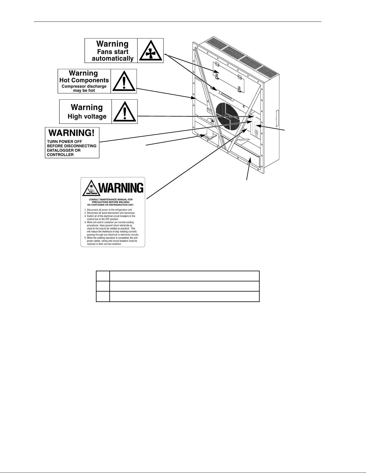
Figure 1: Nameplate and Warning Locations . . . . . . . . . . . . . . . . . . . . . . . . . . . . . . . . . . . . . . . . . . . . . . . . . . . 16
Figure 2: Physical Specifications . . . . . . . . . . . . . . . . . . . . . . . . . . . . . . . . . . . . . . . . . . . . . . . . . . . . . . . . . . . 27
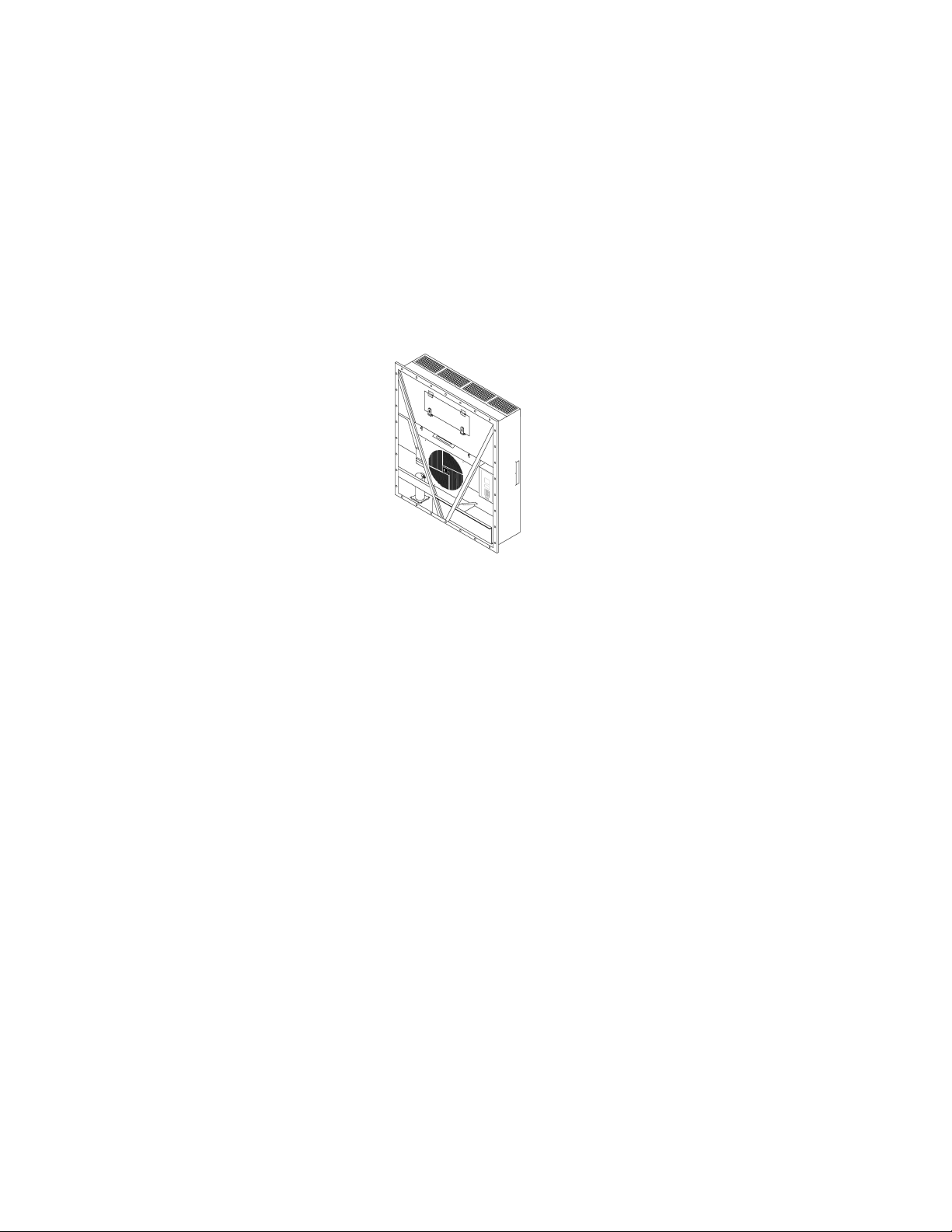
Figure 3: MAGNUM Unit . . . . . . . . . . . . . . . . . . . . . . . . . . . . . . . . . . . . . . . . . . . . . . . . . . . . . . . . . . . . . . . . . . . 29
Figure 4: Scroll Compressor . . . . . . . . . . . . . . . . . . . . . . . . . . . . . . . . . . . . . . . . . . . . . . . . . . . . . . . . . . . . . . . . 30
Figure 5: MP-3000a Controller . . . . . . . . . . . . . . . . . . . . . . . . . . . . . . . . . . . . . . . . . . . . . . . . . . . . . . . . . . . . . . 30
Figure 6: Compressor Digital Control Solenoid Valve . . . . . . . . . . . . . . . . . . . . . . . . . . . . . . . . . . . . . . . . . . . . . 30
Figure 7: Economizer Heat Exchanger . . . . . . . . . . . . . . . . . . . . . . . . . . . . . . . . . . . . . . . . . . . . . . . . . . . . . . . . 31
Figure 8: Fresh Air Exchange Vent . . . . . . . . . . . . . . . . . . . . . . . . . . . . . . . . . . . . . . . . . . . . . . . . . . . . . . . . . . . 31
Figure 9: Fresh Air Exchange Recorder . . . . . . . . . . . . . . . . . . . . . . . . . . . . . . . . . . . . . . . . . . . . . . . . . . . . . . . 31
Figure 10: Receiver Tank Sight Glass . . . . . . . . . . . . . . . . . . . . . . . . . . . . . . . . . . . . . . . . . . . . . . . . . . . . . . . . 32
Figure 11: Optional Components . . . . . . . . . . . . . . . . . . . . . . . . . . . . . . . . . . . . . . . . . . . . . . . . . . . . . . . . . . . 33
Figure 12: Water-Cooled Condenser/Receiver Tank . . . . . . . . . . . . . . . . . . . . . . . . . . . . . . . . . . . . . . . . . . . . . 34
Figure 13: Advanced Fresh Air Management (AFAM+) Option . . . . . . . . . . . . . . . . . . . . . . . . . . . . . . . . . . . . 35
Figure 14: Unit Front View . . . . . . . . . . . . . . . . . . . . . . . . . . . . . . . . . . . . . . . . . . . . . . . . . . . . . . . . . . . . . . . . 36
Figure 15: Unit Back View . . . . . . . . . . . . . . . . . . . . . . . . . . . . . . . . . . . . . . . . . . . . . . . . . . . . . . . . . . . . . . . . . 37
Figure 16: Refrigeration System . . . . . . . . . . . . . . . . . . . . . . . . . . . . . . . . . . . . . . . . . . . . . . . . . . . . . . . . . . . . 38
Figure 17: Electrical Components . . . . . . . . . . . . . . . . . . . . . . . . . . . . . . . . . . . . . . . . . . . . . . . . . . . . . . . . . . . . 39
Figure 18: MP-3000a Controller Display Panel . . . . . . . . . . . . . . . . . . . . . . . . . . . . . . . . . . . . . . . . . . . . . . . . . . 41
Figure 19: Temperature Status Display . . . . . . . . . . . . . . . . . . . . . . . . . . . . . . . . . . . . . . . . . . . . . . . . . . . . . . . 42
Figure 20: Message Display . . . . . . . . . . . . . . . . . . . . . . . . . . . . . . . . . . . . . . . . . . . . . . . . . . . . . . . . . . . . . . . . 42
Figure 21: Special Function Keys . . . . . . . . . . . . . . . . . . . . . . . . . . . . . . . . . . . . . . . . . . . . . . . . . . . . . . . . . . . . 42
Figure 22: Menu Scrolling Keys on Keypad . . . . . . . . . . . . . . . . . . . . . . . . . . . . . . . . . . . . . . . . . . . . . . . . . . . . 43
Figure 23: Text Keys on Keypad . . . . . . . . . . . . . . . . . . . . . . . . . . . . . . . . . . . . . . . . . . . . . . . . . . . . . . . . . . . . . 43
Figure 24: Text Keys . . . . . . . . . . . . . . . . . . . . . . . . . . . . . . . . . . . . . . . . . . . . . . . . . . . . . . . . . . . . . . . . . . . . . . 44
Figure 25: MP-3000a Controller Display Panel . . . . . . . . . . . . . . . . . . . . . . . . . . . . . . . . . . . . . . . . . . . . . . . . . . 45
Figure 26: Unit On/Off Switch . . . . . . . . . . . . . . . . . . . . . . . . . . . . . . . . . . . . . . . . . . . . . . . . . . . . . . . . . . . . . . . 47
Figure 27: Special Function Keys . . . . . . . . . . . . . . . . . . . . . . . . . . . . . . . . . . . . . . . . . . . . . . . . . . . . . . . . . . . . 49
Figure 28: Setpoint Menu . . . . . . . . . . . . . . . . . . . . . . . . . . . . . . . . . . . . . . . . . . . . . . . . . . . . . . . . . . . . . . . . . . 50
Figure 29: Setpoint Menu . . . . . . . . . . . . . . . . . . . . . . . . . . . . . . . . . . . . . . . . . . . . . . . . . . . . . . . . . . . . . . . . . . 52
Figure 30: Setpoint Menu . . . . . . . . . . . . . . . . . . . . . . . . . . . . . . . . . . . . . . . . . . . . . . . . . . . . . . . . . . . . . . . . . . 53
Figure 31: Alarms Menu . . . . . . . . . . . . . . . . . . . . . . . . . . . . . . . . . . . . . . . . . . . . . . . . . . . . . . . . . . . . . . . . . . . 54
Figure 32: Data Menu . . . . . . . . . . . . . . . . . . . . . . . . . . . . . . . . . . . . . . . . . . . . . . . . . . . . . . . . . . . . . . . . . . . . . 57
Figure 33: RMM Menu Screen Flow Diagram . . . . . . . . . . . . . . . . . . . . . . . . . . . . . . . . . . . . . . . . . . . . . . . . . . . 58
Figure 34: Datalogger Menu . . . . . . . . . . . . . . . . . . . . . . . . . . . . . . . . . . . . . . . . . . . . . . . . . . . . . . . . . . . . . . . . 59
Figure 35: Datalogger Menu . . . . . . . . . . . . . . . . . . . . . . . . . . . . . . . . . . . . . . . . . . . . . . . . . . . . . . . . . . . . . . . . 61
Figure 36: Datalogger Menu . . . . . . . . . . . . . . . . . . . . . . . . . . . . . . . . . . . . . . . . . . . . . . . . . . . . . . . . . . . . . . . . 63
Figure 37: Configuration Menu . . . . . . . . . . . . . . . . . . . . . . . . . . . . . . . . . . . . . . . . . . . . . . . . . . . . . . . . . . . . . . 65
Figure 38: Misc. Functions Menu . . . . . . . . . . . . . . . . . . . . . . . . . . . . . . . . . . . . . . . . . . . . . . . . . . . . . . . . . . . . 67
Figure 39: Commands Menu . . . . . . . . . . . . . . . . . . . . . . . . . . . . . . . . . . . . . . . . . . . . . . . . . . . . . . . . . . . . . . . 70
Figure 40: Brief PTI Test . . . . . . . . . . . . . . . . . . . . . . . . . . . . . . . . . . . . . . . . . . . . . . . . . . . . . . . . . . . . . . . . . . . 71
Figure 41: Full PTI Test . . . . . . . . . . . . . . . . . . . . . . . . . . . . . . . . . . . . . . . . . . . . . . . . . . . . . . . . . . . . . . . . . . . 75
Figure 42: Function Test . . . . . . . . . . . . . . . . . . . . . . . . . . . . . . . . . . . . . . . . . . . . . . . . . . . . . . . . . . . . . . . . . . . 79
Figure 43: Manual Function Test . . . . . . . . . . . . . . . . . . . . . . . . . . . . . . . . . . . . . . . . . . . . . . . . . . . . . . . . . . . . 82
Figure 44: Manual Emergency Control Connections . . . . . . . . . . . . . . . . . . . . . . . . . . . . . . . . . . . . . . . . . . . . . 84
Figure 45: AFAM System . . . . . . . . . . . . . . . . . . . . . . . . . . . . . . . . . . . . . . . . . . . . . . . . . . . . . . . . . . . . . . . . . . 85
Figure 46: Vent Door Linkage Adjustment . . . . . . . . . . . . . . . . . . . . . . . . . . . . . . . . . . . . . . . . . . . . . . . . . . . . . 86
Figure 47: Setpoint Menu . . . . . . . . . . . . . . . . . . . . . . . . . . . . . . . . . . . . . . . . . . . . . . . . . . . . . . . . . . . . . . . . . . 87
Figure 48: AFAM+ System . . . . . . . . . . . . . . . . . . . . . . . . . . . . . . . . . . . . . . . . . . . . . . . . . . . . . . . . . . . . . . . . . 88
Figure 49: AFAM+ System . . . . . . . . . . . . . . . . . . . . . . . . . . . . . . . . . . . . . . . . . . . . . . . . . . . . . . . . . . . . . . . . . 89
Figure 50: Setpoint Menu . . . . . . . . . . . . . . . . . . . . . . . . . . . . . . . . . . . . . . . . . . . . . . . . . . . . . . . . . . . . . . . . . . 91
Figure 51: Linkage and Door Adjustment . . . . . . . . . . . . . . . . . . . . . . . . . . . . . . . . . . . . . . . . . . . .
Figure 52: AFAM+ Door Adjustment . . . . . . . . . . . . . . . . . . . . . . . . . . . . . . . . . . . . . . . . . . . . . . . . . . . . . . . . . . 99
Figure 53: Fresh Air Exchange Recorder . . . . . . . . . . . . . . . . . . . . . . . . . . . . . . . . . . . . . . . . . . . . . . . . . . . . . 100
Figure 54: Power Wire Connections . . . . . . . . . . . . . . . . . . . . . . . . . . . . . . . . . . . . . . . . . . . . . . . . . . . . . . . . . 101
Figure 55: Chart Recorder Terminals . . . . . . . . . . . . . . . . . . . . . . . . . . . . . . . . . . . . . . . . . . . . . . . . . . . . . . . . 101
Figure 56: Electronic Chart Recorder Mounting Bolts . . . . . . . . . . . . . . . . . . . . . . . . . . . . . . . . . . . . . . . . . . . . 101
Figure 57: Chill Load Control Sequence (Setpoints at -9.9 C [14.1 F] and Above) . . . . . . . . . . . . . . . . . . . . . . 108
Figure 58: Frozen Load Control Sequence (Setpoints at -10 C [14 F] and Below) . . . . . . . . . . . . . . . . . . . . . . 111
. . . . . . . . . . 98
11

List Of Figures
Figure 59: Compressor Digital Control Solenoid Valve . . . . . . . . . . . . . . . . . . . . . . . . . . . . . . . . . . . . . . . . . . .112
Figure 60: Economizer Heat Exchanger . . . . . . . . . . . . . . . . . . . . . . . . . . . . . . . . . . . . . . . . . . . . . . . . . . . . . .113
Figure 61: Main Circuit Breaker . . . . . . . . . . . . . . . . . . . . . . . . . . . . . . . . . . . . . . . . . . . . . . . . . . . . . . . . . . . . .117
Figure 62: Control System Fuse . . . . . . . . . . . . . . . . . . . . . . . . . . . . . . . . . . . . . . . . . . . . . . . . . . . . . . . . . . . .117
Figure 63: Control Circuit Fuses . . . . . . . . . . . . . . . . . . . . . . . . . . . . . . . . . . . . . . . . . . . . . . . . . . . . . . . . . . . .117
Figure 64: Low and High Pressure Cutout Switches . . . . . . . . . . . . . . . . . . . . . . . . . . . . . . . . . . . . . . . . . . . . .118
Figure 65: High Pressure Cutout Manifold . . . . . . . . . . . . . . . . . . . . . . . . . . . . . . . . . . . . . . . . . . . . . . . . . . . .119
Figure 66: Low and High Pressure Cutout Switches . . . . . . . . . . . . . . . . . . . . . . . . . . . . . . . . . . . . . . . . . . . . .120
Figure 67: Low and High Pressure Cutout Switches . . . . . . . . . . . . . . . . . . . . . . . . . . . . . . . . . . . . . . . . . . . . .121
Figure 68: Pressure Sensor Location . . . . . . . . . . . . . . . . . . . . . . . . . . . . . . . . . . . . . . . . . . . . . . . . . . . . . . . .122
Figure 69: Compressor Discharge Temperature Sensor . . . . . . . . . . . . . . . . . . . . . . . . . . . . . . . . . . . . . . . . . .125
Figure 70: Temperature Sensors . . . . . . . . . . . . . . . . . . . . . . . . . . . . . . . . . . . . . . . . . . . . . . . . . . . . . . . . . . . .126
Figure 71: MAGNUM 20 Evaporator Coil (Defrost) Sensor Location . . . . . . . . . . . . . . . . . . . . . . . . . . . . . . . .127
Figure 72: MAGNUM and MAGNUM SL Evaporator Coil (Defrost) Sensor Location . . . . . . . . . . . . . . . . . . . .127
Figure 73: Condenser Coil Sensor Location . . . . . . . . . . . . . . . . . . . . . . . . . . . . . . . . . . . . . . . . . . . . . . . . . . .127
Figure 74: Service Fittings Specifications . . . . . . . . . . . . . . . . . . . . . . . . . . . . . . . . . . . . . . . . . . . . . . . . . . . . .129
Figure 75: Service Valve Back Seated . . . . . . . . . . . . . . . . . . . . . . . . . . . . . . . . . . . . . . . . . . . . . . . . . . . . . . .130
Figure 76: Service Valve Open to Port . . . . . . . . . . . . . . . . . . . . . . . . . . . . . . . . . . . . . . . . . . . . . . . . . . . . . . .130
Figure 77: Service Valve Front Seated . . . . . . . . . . . . . . . . . . . . . . . . . . . . . . . . . . . . . . . . . . . . . . . . . . . . . . .130
Figure 78: Balancing the Pressure . . . . . . . . . . . . . . . . . . . . . . . . . . . . . . . . . . . . . . . . . . . . . . . . . . . . . . . . . .130
Figure 79: Removing Refrigerant . . . . . . . . . . . . . . . . . . . . . . . . . . . . . . . . . . . . . . . . . . . . . . . . . . . . . . . . . . .131
Figure 80: Gauge Manifold Closed to Center Port . . . . . . . . . . . . . . . . . . . . . . . . . . . . . . . . . . . . . . . . . . . . . .131
Figure 81: Gauge Manifold Open to Center Port . . . . . . . . . . . . . . . . . . . . . . . . . . . . . . . . . . . . . . . . . . . . . . . .131
Figure 82: Charging the System . . . . . . . . . . . . . . . . . . . . . . . . . . . . . . . . . . . . . . . . . . . . . . . . . . . . . . . . . . . .131
Figure 83: Purging Gauge Manifold . . . . . . . . . . . . . . . . . . . . . . . . . . . . . . . . . . . . . . . . . . . . . . . . . . . . . . . . . .132
Figure 84: Receiver Tank Sight Glass . . . . . . . . . . . . . . . . . . . . . . . . . . . . . . . . . . . . . . . . . . . . . . . . . . . . . . . .133
Figure 85: Test for Refrigerant Leaks . . . . . . . . . . . . . . . . . . . . . . . . . . . . . . . . . . . . . . . . . . . . . . . . . . . . . . . .134
Figure 86: Typical Pressurized Gas Bottle with Pressure Regulator and Gauges . . . . . . . . . . . . . . . . . . . . . .134
Figure 87: Evacuation Station and Unit Hook-up . . . . . . . . . . . . . . . . . . . . . . . . . . . . . . . . . . . . . . . . . . . . . . 136
Figure 88: Constant Pressure Rise After Evacuation Indicates System Leak . . . . . . . . . . . . . . . . . . . . . . . . . .140
Figure 89: Pressure Rise Levels Off After Evacuation Indicates Moisture in System . . . . . . . . . . . . . . . . . . . .140
Figure 90: Scroll Compressor . . . . . . . . . . . . . . . . . . . . . . . . . . . . . . . . . . . . . . . . . . . . . . . . . . . . . . . . . . . . . .142
Figure 91: Filter Drier . . . . . . . . . . . . . . . . . . . . . . . . . . . . . . . . . . . . . . . . . . . . . . . . . . . . . . . . . . . . . . . . . . . . .144
Figure 92: TXV Valve and Element Location . . . . . . . . . . . . . . . . . . . . . . . . . . . . . . . . . . . . . . . . . . . . . . . . . . .145
Figure 93: Economizer Heat Exchanger (Before January 2003) . . . . . . . . . . . . . . . . . . . . . . . . . . . . . . . . . . . .146
Figure 94: Economizer Expansion Valve and Heat Exchanger (After January 2003) . . . . . . . . . . . . . . . . . . . .146
Figure 95: Receiver Tank . . . . . . . . . . . . . . . . . . . . . . . . . . . . . . . . . . . . . . . . . . . . . . . . . . . . . . . . . . . . . . . . .148
Figure 96: Water-Cooled Condenser Tank . . . . . . . . . . . . . . . . . . . . . . . . . . . . . . . . . . . . . . . . . . . . . . . . . . . .148
Figure 97: Vapor Injection Valve . . . . . . . . . . . . . . . . . . . . . . . . . . . . . . . . . . . . . . . . . . . . . . . . . . . . . . . . . . . .149
Figure 98: Digital Control Valve . . . . . . . . . . . . . . . . . . . . . . . . . . . . . . . . . . . . . . . . . . . . . . . . . . . . . . . . . . . . .150
Figure 99: Mounting Bolts . . . . . . . . . . . . . . . . . . . . . . . . . . . . . . . . . . . . . . . . . . . . . . . . . . . . . . . . . . . . . . . . .151
Figure 100: Condenser Fan Blade Placement . . . . . . . . . . . . . . . . . . . . . . . . . . . . . . . . . . . . . . . . . . . . . . . . .152
Figure 101: Evaporator Fan Blade Placement . . . . . . . . . . . . . . . . . . . . . . . . . . . . . . . . . . . . . . . . . . . . . . . . .152
Figure 102: Air Exchange System . . . . . . . . . . . . . . . . . . . . . . . . . . . . . . . . . . . . . . . . . . . . . . . . . . . . . . . . . . .153
12

Safety Instructions
General Precautions
• Always wear goggles or safety glasses.
Refrigerant liquid and battery acid can
permanently damage the eyes.
• Never operate the unit with the discharge
valve closed. Never close the compressor
discharge valve with the unit in operation.
• Keep your hands, clothing and tools clear of
the fans when the refrigeration unit is running.
If it is necessary to run th e ref rigeration unit
with covers removed, be very careful with
tools or meters being used in the area.
• Check the condition of the gauge manifold
hoses. Never let the hoses come in contact
with a fan motor blade or any hot surface.
• Never apply heat to a sealed refr igeration
system or container.
• Fluorocarbon refrigerants produce toxic gases
in the presence of an open flame or electrical
arc. The gases are severe respiratory irrit ants
capable of causing death.
• Firmly tighten all mounting bolts. Check each
bolt for correct length for their particular
application.
• Use extreme caution when drilling holes in the
unit. The holes may weaken structural
components. Holes drilled into electrical
wiring can cause fire or ex plosion. Holes
drilled into the refrigeration system may
release refrigerant.
• Use caution when working around expos e d
coil fins. The fins can cause painful
lacerations.
• Use caution when working with a refrigerant
or refrigeration system in any closed or
confined area with a limited air supply (for
example, a trailer, container or in the hold of a
ship). Refrigerant tends to displace air and can
cause oxygen depletion. This can result in
suffocation and possible death.
• Use caution and follow t he manufacturer’s
suggested pract i c es wh en us in g la d de rs or
scaffolds
.
Refrigerant Oil Precautions
Observe the following precautions when work ing
with or around refrigerant oil:
• Do not allow refrigerant oil to contact your
eyes.
• Rubber gloves are recommen ded when
handling Poly ol Ester based refrigerant oil.
• Do not allow prolonged or repeated contact
with skin or clothing.
• Immediately wash all exposed skin after
handling refrigerant oil.
Use the following First Aid practices if needed.
Eyes: Immediately fl ush ey es wi th lar ge a mount s
of water. Continue flushing for at least 15 minutes
while holding the eyelids open. Get prompt
medical attention.
Skin: Remove contaminated clothing. Wash
thoroughly with s oap and water. Get medical
attention if irri tation persists.
Inhalation: Move victim to fresh air. Restore
breathing if necess a ry. Stay with victim until
arrival of emergency pers onnel.
Ingestion: Do not induce vomiting. Contact a
local poison control cen ter or physician
immediately.
Electrical Precautions
The possibility of serious or f a tal injury from
electrical shock exists when servicing a
refrigeration unit. Extreme car e must be used
when working with a refriger ation unit that is
connected to its power source. Extreme care must
be used even if the unit is not running . Let hal
voltage potentials can exist at the unit power cord,
inside the control box, inside any high voltage
junction box, at the motors and within the wiring
harnesses.
Precautions
• Turn the unit On/Off switch to Off before
connecting or disconnecting the unit p ower
plug. Never attempt to stop the unit by
disconnectin g th e po we r pl ug .
13

Safety Instructions
• Be certain the unit power plug is clean and dry
before connecting it to a power source.
• Use tools with insulated handles. Use tools
that are in good con dition. Never hold metal
tools in your hand if exposed, energized
conductors are within reach.
• Do not make any rapid moves when working
with high voltage circuits. Do not grab a
falling tool or other object. Peop le do not
contact high voltage wires on purpose. It
occurs from an unplanned movement.
• Treat all wires and connections as high
voltage until ammeter and wiring d iagram
show otherwise.
• Never work alone on high voltage circuits on
the refrigeration unit. Another person should
always be standing by in the event of an
accident to shut off the refrigeration unit and
to aid a victim.
• Have electrically insulated gloves, cable
cutters and safety glasses availab le in the
immediate vicinity in the event of an accident.
First Aid
IMMEDIATE action must be initiated after a
person has received an electrical shock. Obtain
immediate medical assistance.
The source of shock must be immediately
removed. Sh ut down the power or remove the
victim from the source. If it is not possible to shut
off the power, the wire should be cut with either
an insulated inst rument (e.g., a wooden handled
axe or cable cutters with heavy insulated handles).
A rescuer wearing electrically insulated gloves
and safety glasses could also cut the wire. Do not
look at the wire while it is being cut. The ensuing
flash can cause burns and blindn ess.
Pull the victim off with a non-conductive material
if the victim has to be removed from a live circuit.
Use the victim’s coat, a rope, wood, or loop your
belt around the victim ’s leg or arm and pull the
victim off. Do not touch the victim. You can
receive a shock from current flowing thr ough the
victim’s body.
Check immediately for the presence of a pulse and
respiration afte r sep ara tin g the vic tim fr om p ower
source. If a pulse is not present, start CPR (Cardio
Pulmonary Resuscitation) and call for emergency
medical assistance. Respiration may also be
restored by using mou th-to-mouth resuscitation.
Low Voltage
Control circuits are low voltage (24 Vac and 12
Vdc). This voltage potent ial is not considered
dangerous. Large amount of curr ent available
(over 30 amperes) can cause severe burns if
shorted to ground. Do not wear jewelry, watch or
rings. These items can shortcut electrical circuits
and cause severe burns to the wearer.
Electrostatic Discharge Precautions
Precautions must be taken to prevent electrostatic
discharge while servicing the MP-3000a
microprocessor an d re l ate d co mponents. The risk
of significant damage to the electro nic
components of the unit is possible i f th ese
precautionary measures are not followed. The
primary risk poten tial results from the failure to
wear adequate electrostatic discharge preventive
equipment when handling and servicing the
controller. The second cause results from electric
welding on the unit and container chassis without
taking precautionary steps.
Electrostatic Discharge and the Controller
You must avoid electrostatic discharges when
servicing the controller. Solid-state integrated
circuit compon ents can be severely damaged or
destroyed with less than a small spark from a
finger to metal object. You must rigidly adhere to
the following statements when servicing these
units. This will avoid controller damage or
destruction.
• Disconnect all power to the unit.
• Avoid wearing clothing that generates static
electricity (wool, nylon, polyester, etc.).
• Do wear a static discharge wrist strap (refer to
Tool Catalog) with the lead end connected to
the controller's ground terminal. These straps
14

Safety Instructions
are available at most electronic eq uipment
distributors. Do not wear these straps with
power applied to the unit.
• Avoid contacting the electron ic components
on the circuit boards of the unit being
serviced.
• Leave the circuit boards in their static proof
packing materials unti l ready for installation.
• Return a defective controller for repair in the
same static protective packing materials from
which the replacement component was
removed.
• Check the wiring after serv icing the unit for
possible errors. Complete this task before
restoring power.
Welding of Units or Containers
Electric welding can cause serious damage to
electronic circuits when performed on any portion
of the refrigeration unit, container or container
chassis with the refrigerat ion unit attached. It is
necessary to ensure that welding currents are not
allowed to flow through the electronic circuits of
the unit. The following statements must be rigidly
adhered to when servicing these units to avoid
damage or destruction.
• Disconnect all power to the refrigeration unit.
• Disconnect all quick-disconnect wire
harnesses from the back of the controller.
• Disconnect all wire ha rnesses from the
Remote Monitor Modem (RMM).
• Switch all of the electrical circuit breakers in
the control box to the Off position.
• Weld unit and/or container per normal
welding procedures. Keep ground return
electrode as close to the area to be welded as
practical. This will reduce the likelihood of
stray welding currents passing through any
electrical or electronic circuits.
• The unit power cables, wiring and circuit
breakers must be restored to their normal
condition when t he welding operation is
completed.
Removing Refrigerant Properly
Use a refrigerant recovery process that prevents or
absolutely minimizes refrigerant escaping to the
atmosphere. Fluorocarbon refrigeran ts are
classified as safe refrigerants when pr oper tools
and procedures are used. Certain precautions must
be observed when handling them or servicing a
unit in which they are used.
Fluorocarbon refrigerants evaporate rapidly,
freezing anything they contact when exposed to
the atmosphere in the liquid state. In the event of
frost bite, attempt to protect the frozen area from
further injury, warm the affected area rapidly , and
maintain respiration.
• Eyes: For contact with liquid, immediately
flush eyes with large amounts of water and get
prompt medical atten ti on .
• Skin: Flush area with large amounts of
lukewarm water. Do not apply heat. Remove
contaminated clothing and shoes. Wrap burns
with dry, sterile, bulky dressing to protect
from infection/injury. Get medical attention.
Wash contaminated clothing before reuse.
• Inhalation: Move victim to fresh air and use
CPR or mouth-to-m ou t h ve nt ilation, if
necessary. Stay with victim un til arrival of
emergency medical personnel.
15
Safety Instructions
AXA0214
AXA0215
AXA0217
AXA0216
1
3
AMA306
2
AXA0218
1. Controller Nameplate
2. Unit Nameplate
3. Compressor Nameplate
Figure 1: Nameplate and Warning Locations
Identifying Unit Safety and Warning Decals
Serial number decals, refrig erant type decals and
warning decals appear on all Thermo King
equipment. These decals provide information that
may be needed to service or repair the unit.
Service technicians should read and follow the
instructions on all warning decals. See above
figure.
16
®
Locating Serial Numbers
Serial numbers can be found on the component’s
nameplate.
• Electric Motor Nameplate: Attached to the
motor housing.
• Compressor Nameplate: On front of the
compressor.
• Unit Nameplate: On unit frame in p ower cord
storage compartment.
• MP-3000a Controller Nameplate: On back
of controller.
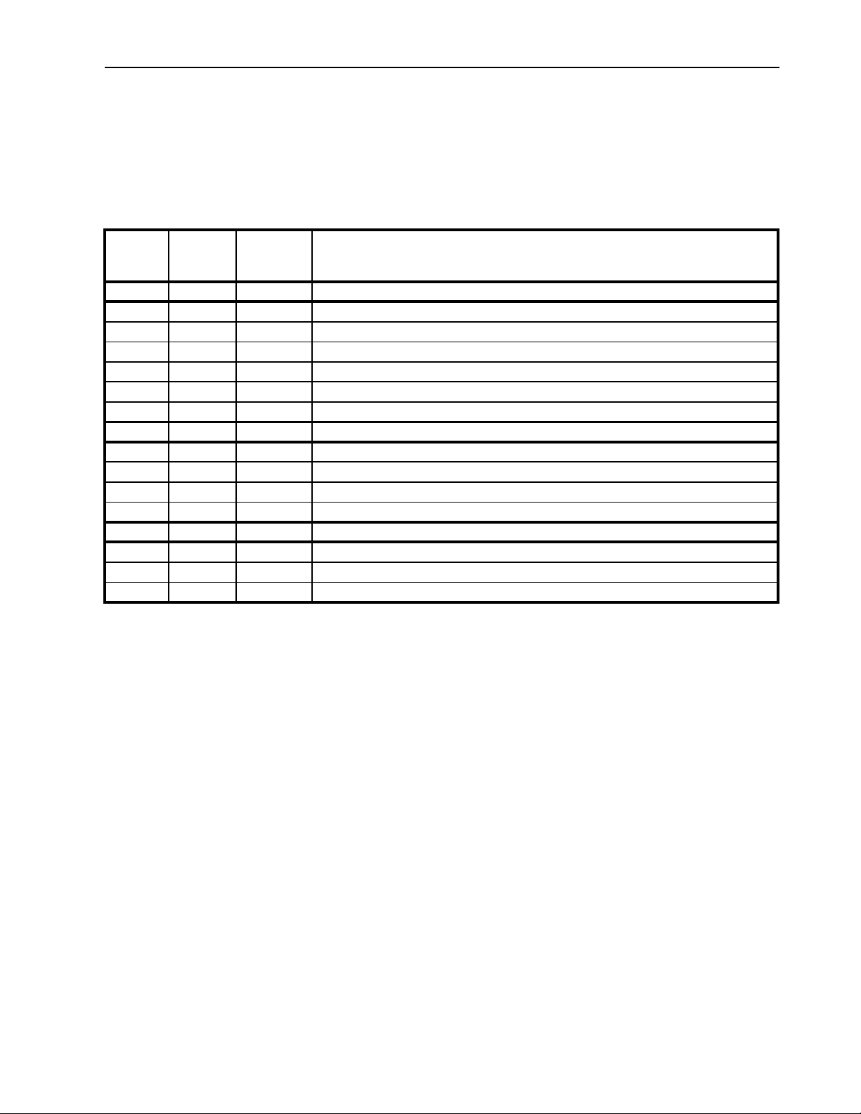
Service Guide
Service Guide
A closely followed mai nt e nance program will help to kee p yo ur Thermo King unit in top ope ra ti ng
condition.
The following service guide table should be used as a guide when inspecting or servicing components on
this unit.
Every
Pretrip
• Perform a controller pretrip inspection (PTI) check.
• • • Visually check condenser fan and evaporator fan.
• • • Visually inspect electrical contacts for damage or loose connections.
• • • Visually inspect wire harnesses for damage or loose connections.
• • • Check refrigerant charge.
• • • Check compressor oil level.
• • • Visually inspect unit for damaged, loose or broken parts.
• • • Tighten unit, compressor and fan motor mounting bolts.
1,000
Hours
• • Download the data logger and check data for correct logging.
• • Check for proper discharge and suction pressures.
• • Clean entire unit including condenser and evaporator coils, and defrost drains.
Annual/
Yearly
Electrical
• Check operation of protection shutdown circuits.
Refrigeration
• Check filter drier/in-line filter for a restriction pressures.
Structural
Inspect/Service These Items
17

Service Guide
18

Specifications
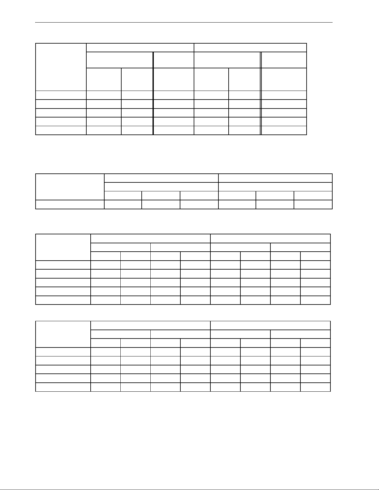
System Net Cooling Capacity— Full Cool
MAGNUM, MAGNUM SL Models — Air Cooled Condensing*
460/230V, 3 Phase, 60 Hz Power 380/190V, 3 Phase, 50 Hz Power
Return air to
evaporator coil
inlet
21.1 C (70 F) 54,000 15.813 11.8 46,000 13.470 9.2
1.7 C (35 F) 42,000 12.299 11.2 36,000 10.542 8.7
-17.8 C (0 F) 25,000 7.321 7.8 21,300 6.237 6.2
-28.9 C (-20 F) 17,300 5.066 6.9 14,400 4.217 5.4
-35 C (-31 F) 14,000 4.100 6.4 12,000 3.514 5.0
Net Cooling Capacity Power
Consump
60 Hz
Capacity
B/hr
*System net cooling capacity with a 37.8 C (100 F) ambient air temperature and R-404A.
60 Hz
Capacity
kW
60 Hz Power kW50 Hz
MAGNUM, MAGNUM SL Models — Wa ter Cooled Condensing*
460/230V, 3 Phase, 60 Hz Power
Return air to
evaporator coil
inlet
2 C (35 F) 23,850 6.990 9.2
-18 C (0 F) 23,066 6.760 8.0
-29 C (-20 F) 17,333 5.080 6.5
-35 C (-31 F) 13,887 4.070 5.9
*Unit capacity water cooled condenser at 37.8 C (100 F) water
temperature at 60 HZ power @30 liter/min (8 Gal/min)
Net Cooling Capacity Power
Consump
60 Hz
Capacity
B/hr
60 Hz
Capacity
kW
60 Hz Power
kW
Net Cooling Capacity Power
Consump
50 Hz Power
Capacity
B/hr
50 Hz
Capacity
kW
kW
MAGNUM, MAGNUM SL Models — Wa ter Cooled Condensing*
460/230V, 3 Phase, 60 Hz Power
Return air to
evaporator coil
inlet
2 C (35 F) 35076 10.280 10.9
-18 C (0 F) 25113 7.360 6.9
-29 C (-20 F) 21598 6.330 7.5
-35 C (-31 F) 15115 4.430 5.2
*Unit capacity water cooled condenser at 30 C (86 F) water
temperature at 60 HZ power @30 liter/min (8 Gal/min)
Net Cooling Capacity Power
60 Hz
Capacity
B/hr
60 Hz
Capacity
kW
60 Hz Power
Consump
kW
19
Specifications
MAGNUM 20 Model — Air Cooled Condensing*
460/230V, 3 Phase, 60 Hz Power 380/190V, 3 Phase, 50 Hz Power
Return air to
evaporator coil
inlet
21.1 C (70 F) 49,000 14.348 11.6 41,800 12.240 9.1
1.7 C (35 F) 31,800 11.157 10.8 32,800 9.605 8.4
-17.8 C (0 F) 22,700 6.647 7.2 19,100 5.593 5.7
-28.9 C (-20 F) 15,700 4.597 6.1 13,300 3.895 4.8
-35 C (-31 F) 12,700 3.719 5.5 11,400 3.338 4.3
Net Cooling Capacity Power
Consump
60 Hz
Capacity
B/hr
*System net cooling capacity with a 37.8 C (100 F) ambient air temperature and R-404A.
60 Hz
Capacity
kW
60 Hz Power kW50 Hz
Net Cooling Capacity Power
Consump
50 Hz Power
kW
Capacity
B/hr
50 Hz
Capacity
kW
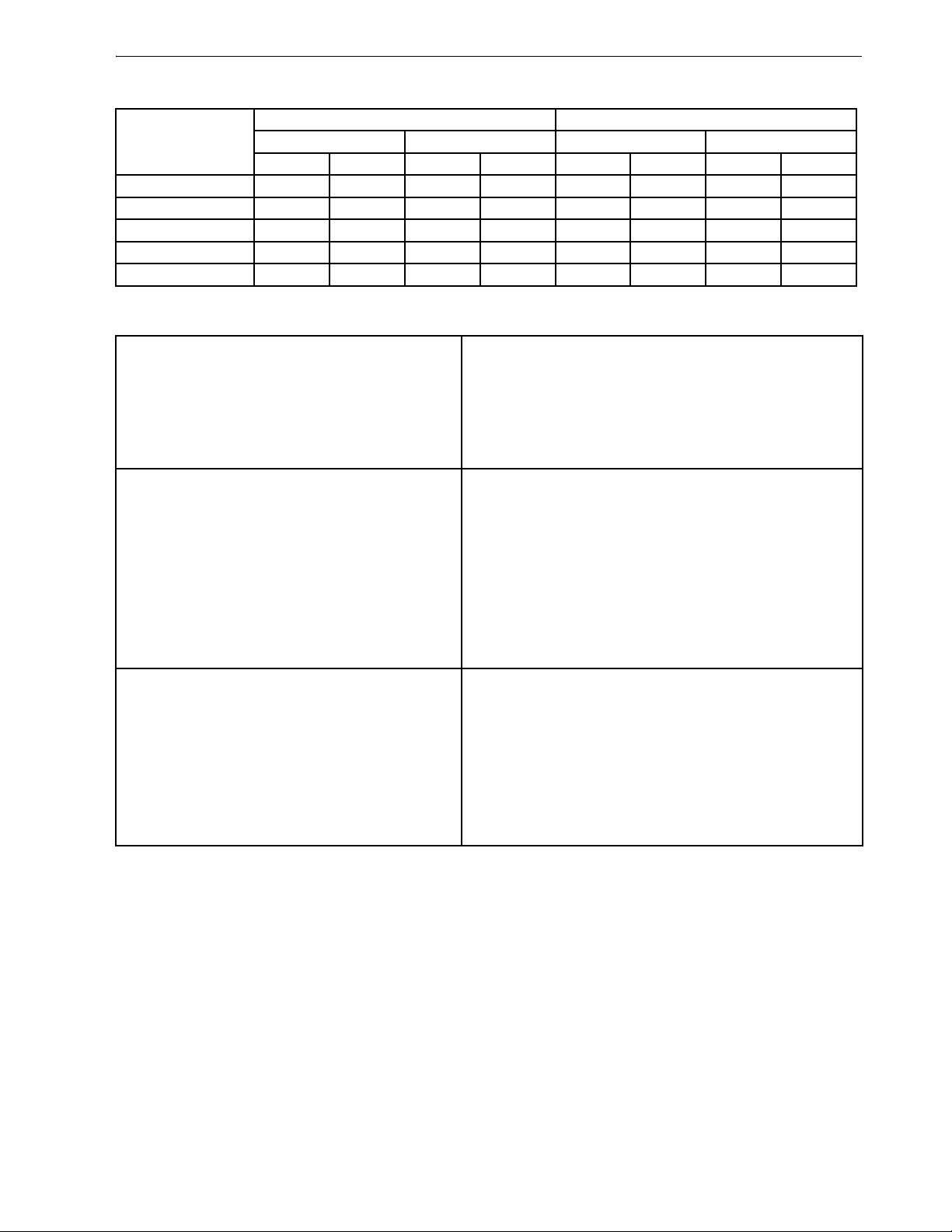
Evaporator Airflow Specifications
System Net Heating Capacity*
460/230V, 3 Phase, 60 Hz Power 380/190V, 3 Phase, 50 Hz Power
Heating Capacity Heating Capacity
Watts Kcal/hr BTU/hr Watts Kcal/hr BTU/hr
MAGNUM 5,800 4,990 19,800 4,900 4,215 16,720
*System net heating capacity includes electric resistance rods and fan heat.
MAGNUM
External Static
Pressure (water
column)
0 mm (0 in.) 6,560 3,860 3,170 1,865 5,480 3,225 2,710 1,595
10 mm (0.4 in.) 5,820 3,425 1,770 1,040 4,530 2,665 930 545
20 mm (0.8 in.) 5,000 2,940 — — 3,750 2,205 — —
30 mm (1.2 in.) 4,430 2,610 — — 2,930 1,725 — —
40 mm (1.6 in.) 3,520 2,070 — — 1,870 1,100 — —
460/230V, 3 Phase, 60 Hz Power 380/190V, 3 Phase, 50 Hz Power
High Speed Low Speed High Speed Low Speed
3
m
/hr ft3/min m3/hr ft3/min m3/hr ft3/min m3/hr ft3/min
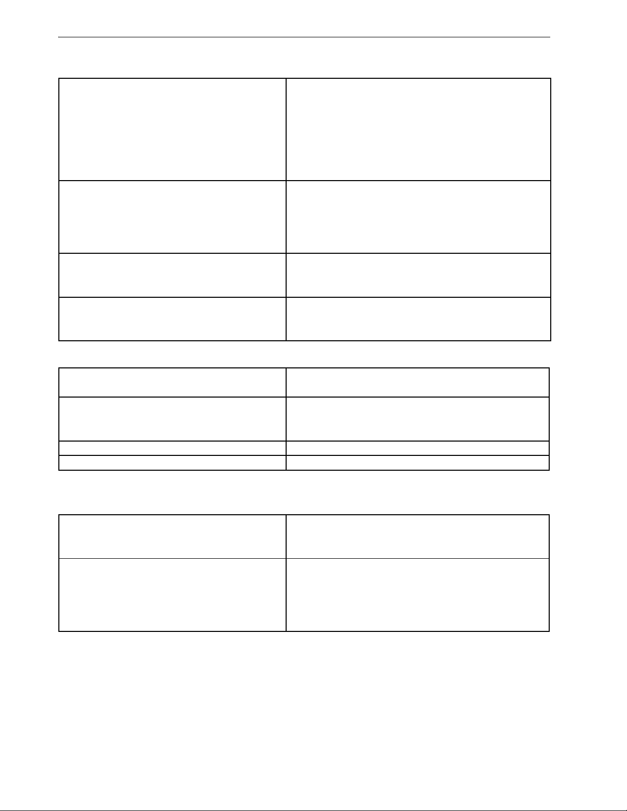
MAGNUM SL
External Static
Pressure (water
column)
0 mm (0 in.) 5,658 3,330 2,773 1,632 4,715 2,775 2,311 1,360
10 mm (0.4 in.) 5,097 3,000 1,612 949 4,248 2,500 1,344 791
20 mm (0.8 in.) 4,417 2,600 510 300 3,682 2,167 425 250
30 mm (1.2 in.) 3,908 2,300 — — 3,257 1,917 — —
40 mm (1.6 in.) 3,228 1,900 — — 2,690 1,583 — —
460/230V, 3 Phase, 60 Hz Power 380/190V, 3 Phase, 50 Hz Power
High Speed Low Speed High Speed Low Speed
3
m
/hr ft3/min m3/hr ft3/min m3/hr ft3/min m3/hr ft3/min
20
Specifications
MAGNUM 20
External Static
Pressure (water
column)
0 mm (0 in.) 4,000 2,350 2,000 1,180 3,300 1,940 1,650 970
10 mm (0.4 in.) 3,500 2,060 1,450 850 2,600 1,530 900 530
20 mm (0.8 in.) 2,900 1,710 — — 1,800 1,060 — —
30 mm (1.2 in.) 2,200 1,300 — — 1,100 650 — —
40 mm (1.6 in.)1,400820——————
460/230V, 3 Phase, 60 Hz Power 380/190V, 3 Phase, 50 Hz Power
High Speed Low Speed High Speed Low Speed
3
m
/hr ft3/min m3/hr ft3/min m3/hr ft3/min m3/hr ft3/min
Electrical System Specificatio ns
Compressor Motor:
Type 460/380V, 60/50 Hz, 3 Phase
Kilowatts 4.48 kW @ 460V, 60 Hz
Horsepower 6.0 hp @ 460V, 60 Hz
RPM 3550 RPM @ 460V, 60 Hz
Locked Rotor Amps 70 amps @ 460V, 60 Hz
Condenser Fan Motor:
Type 460/380V, 60/50 Hz, 3 Phase
Kilowatts 0.55 kW @ 460V, 60 Hz
Horsepower 0.75 hp @ 460V, 60 Hz
Number: All Models 1
Motor:
RPM 1725 RPM @ 460V, 60 Hz
Full Load Amps 1.0 amps @ 460V, 60 Hz; 1.0 amps @ 380V, 50 Hz
Locked Rotor Amps 3.9 amps @ 460V, 60 Hz; 3.7 amps @ 380V, 50 Hz
Evaporator Fan Motors:
Type 460/380V, 60/50 Hz, 3 Phase
Kilowatts 0.75 kW @ 460V, 60 Hz
Horsepower 1.0 hp @ 460V, 60 Hz
Number:
CSR20SL 3
CSR40SL 2
CSR40 2
21
Specifications
Electrical System Specifications
Motor:
RPM (Each): High Speed 3450 RPM @ 460V, 60 Hz
Low Speed 1725 RPM @ 460V, 60 Hz
Full Load Amps (Each): High Speed 1.6 amps @ 460V, 60 Hz
Low Speed 0.8 amps @ 460V, 60 Hz
Locked Rotor Amps: High Speed 10.5 amps @ 460V, 60 Hz
Low Speed 9.0 amps @ 460V, 60 Hz
Electrical Resistance Heater Rods:
Type 460/380V, 60/50 Hz, 3 Phase
Number 6
Watts (Each) 680 Watts @ 460V, 60 Hz
Current Draw (Amps) 5 amps total @ 460V across each phase at heater contractor
Control Circuit Voltage:
29 Vac @ 60 Hz
24 Vac @ 50 Hz
Evaporator Overheat Switch:
Opens 54 ± 3 C (130 ± 5 F)
Closes 32 ± 4.5 C (90 ± 8 F)
Refrigeration System Specifications
Compressor:
Model No.: ZMD18KVE-TFD-277, Scroll
Refrigerant Charge:
MAGNUM, MAGNUM SL, MAGNUM 20 4.0 Kg (8.0 lb.) R-404A
Water-Cooled Condenser-Receiver Tank (Option) 4.8 Kg (8.8 lb.) R-404A
Compressor Oil Capacity 1.77 liter (60 oz.)*
Compressor Oil Type: Polyol Ester Based Type (required), (refer to Tool Catalog)**
*When the compressor is removed from the unit, oil level should be noted or the oil removed from the compressor should be
measured so that the same amou nt of oil can be maintained in the replacement co mpressor.
**Do not use or add standard synthetic or mineral oils to th e refrigeration system. If Ester based oil becomes contaminated
with moisture or with standard oils, dispose of properly — Do Not Use!
High Pressure Cutout Switch:
Cutout 3240 ± 48 kPa, 32.4 ± 0.5 bar, 470 ± 7 psig
Cutin 2586 ± 262 kPa, 25.9 ± 2.6 bar, 375 ± 38 psig
Low Pressure Cutout Switch:
Cutout -17 to -37 kPa, -0.17 to -0.37 bar, 5 to 11 in. Hg vacuum
Cutin 28 to 48 kPa, 0.28 to 0.48 bar, 4 to 7 psig
High Pressure Relief Valve:
Relief Temperature 99 C, 210 F
22
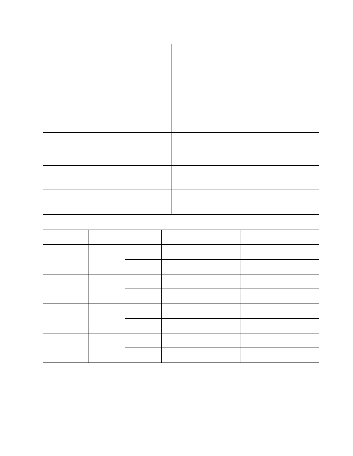
Refrigeration System Specifications (Continued)
Vapor Injection Control:
V apor injection valve is energized (open) continuously when
the compressor duty cycle (ON time) is 100 percent (Full
Modulation Cool or Power Limit
Compressor Discharge Temperature Control:
Vapor Injection Valve Energizes (Opens) 138 C (280 F)
Vapor Injection Valve De-energizes (Closes)
Compressor Shutdown (Auto Reset) 148 C (298 F)
Vapor Injection Valve (Compressor):
Voltage 24 Vac
Current 0.85 amps
Cold Resistance 5.6 ohms
Compressor Digital Control Valve:
Voltage 24 Vac
Current Draw 0.85 amps
Water Pressure Switch (Option):
Close 117 ± 21 kPa, 1.17 ± 0.20 bar, 17 ± 3 psig
Open 35 ± 21 kPa, 0.35 ± 0.20 bar, 5 ± 3 psig
Cool). High compressor discharge temperature may cause
the vapor injection valve to energize (open) but only while
the Compressor Digital Control valve is not energized
(closed).
6 C (10.7 F) below energize temperature
(132 C [123 F])
Specifications
Normal R-404A System Operating Pressures (Scroll Compressor)
Container T emp.
21 C (70 F) Cool
2 C (35 F) Cool
-18 C (0 F) Cool
-29 C (-20 F) Cool
Suction and discharge pressures vary too greatly during Modulation Cool to use for evaluating or diagnosing refrigeration
system performa nce. Durin g the Mod ulation Cool mode, th e suc tion p ressu re will v ary b etwee n 10 0 and 450 kP a, 1.0 and 4.5
bar, 15 and 65 psig depe nding upon the percent (per cent) coolin g capacity.
**Discharge pressure is determined by condenser fan cycling.
Operating
Mode
Ambient
Temp.
27 to 38 C, 80
to 100 F
16 to 27 C, 60
to 80 F
27 to 38 C, 80
to 100 F
16 to 27 C, 60
to 80 F
27 to 38 C, 80
to 100 F
16 to 27 C, 60
to 80 F
27 to 38 C, 80
to 100 F
16 to 27 C, 60
to 80 F
Suction Pressure Discharge Pressure
410 to 670 kPa, 4.10 to 6.70
bar, 59 to 97 psig
400 to 600 kPa, 4.00 to 6.00
bar, 58 to 87 psig
385 to 425 kPa, 3.85 to 4.25
bar, 56 to 62 psig
345 to 385 kPa, 3.45 to 3.85
bar, 50 to 56 psig
214 to 228 kPa, 2.14 to 2.28
bar, 31 to 33 psig
200 to 215 kPa, 2.00 to 2.15
bar, 29 to 31 psig
145 to 160 kPa, 1.45 to 1.60
bar, 21 to 23 psig
130 to 145 kPa, 1.30 to 1.45
bar, 19 to 21 psig
2140 to 2650 kPa, 21.40 to
26.50 bar, 310 to 385 psig
1725 to 2140 kPa, 17.25 to
21.40 bar, 250 to 310 psig
1860 to 2380 kPa, 18.60 to
23.80 bar, 270 to 345 psig
1450 to 1860 kPa, 14.50 to
18.60 bar, 210 to 270 psig**
1515 to 2035 kPa, 15.15 to
20.35 bar, 220 to 295 psig**
1100 to 1515 kPa, 11.00 to
15.15 bar, 160 to 220 psig**
1450 to 1965 kPa, 14.50 to
19.65 bar, 210 to 285 psig**
1035 to 1450 kPa, 10.35 to
14.50 bar, 150 to 210 psig**
23
Specifications
MP-3000a Controller Specifications
Temperature Controller:
MP-3000a microprocessor with thermostat, digital thermometer,
Type
Setpoint Range -35.0 to +30.0 C (-31.0 to +86.0 F)
Digital Temperature Display -60.0 to +80.0 C (-76.0 to +176.0 F)
Controller Software (Original Equipment):
Version See controller identification decal
Defrost Initiation:
Evaporator Coil Sensor
Demand Defrost
Defrost Timer:
Chilled mode
Frozen mode
Reset to Base Time
Defrost Termination:
Defrost (Coil) Sensor
Termination Timer
Power Off Turning Unit On/Off switch Off terminates defrost
programming keypad, mode indicators, LED display and LCD
display for displaying unit operating and cargo information
• Manual Switch or Demand Defrost Initiation: Coil must be
below 18 C (65 F). Defrost cycle starts when technician or
controller requests defrost initiation.
• Timed Defrost Initiation: Coil must be below 10 C (50 F).
Defrost cycle starts 1 minute after the hour immediately following
a defrost timer request for defrost initiation. For example, if the
defrost timer requests a defrost cycle at 7:35, the defrost cycle
will start at 8:01. Datalogger will record a Defrost event for each
interval in which a Defrost cycle is pending or active (i.e. both the
8:00 and 9:00 data logs).
Demand defrost function initiates defrost when:
• Temperature difference between the return air sensor and
defrost (evaporator coil) sensor is too large for 90 minutes
• Temperature difference between the left hand and right hand
supply air sensors is too large and unit has operated for 90
minutes since last defrost
• Temperature difference between the supply air sensors and
return air sensor is too large
• Supply Temperature at 5.1 C (41.2 F) or Above: Every 8 hours
of compressor operation.
• Supply Temperature at 5.0 C (41.0 F) or Below: Every 2.5
hours of compressor operation. Defrost interval increases 0.5
hours each timed defrost interval. Defrost synchronization
creates step intervals of 3, 4, 4, 5, 5, 6, 6 and 7 hours. Maximum
time interval in Chilled mode is 7 hours.
Every 8 hours of compressor operation. Defrost interval increases 2
hours each timed defrost interval. Maximum time interval in Frozen
mode is 24 hours.
Defrost timer resets if the unit is off more than 12 hours, setpoint is
changed more than 5 C (9 F) or PTI pretrip test occurs.
Chilled mode: Terminates defrost when coil sensor temperature
rises to 30 C (86 F); or exceeds 18 C (65 F) for 35 minutes/45
minutes if voltage is less than 440 volts.
Frozen mode: Terminates defrost when coil sensor temperature
rises to 30 C (86 F); or exceeds 8 C (46 F) for 35 minutes/45
minutes if voltage is less than 440 volts.
Terminates defrost after 90 minutes at 60 HZ operation if coil
sensor has not terminated defrost (120 minutes at 50 Hz operation)
24
MP-3000a Controller Specifications (Continued)
Compressor Shutdown Protection
(Auto Reset):
Stops Compressor 148 C (298 F)
Allows Compressor Start 90 C (194 F)
Bulb Mode:
Flow High: High speed only
Evaporator Fan Speed Settings
Defrost Termination Temperature Setting 4 to 30 C (40 to 86 F)
Flow Low: Low speed only
Flow Cycle: Fans will cycle between low and high speed every 60
minutes
Specifications
25
Specifications
Physical Specifications
Fresh Air Exchange Venting System
(Adjustable):
MAGNUM and MAGNUM SL
0 to 285 m
0 to 237 m
0 to 160 m
MAGNUM 20
0 to 134 m
Evaporator Fan Blade Specifications:
MAGNUM:
Diameter 355 mm (14.0 in.)
Pitch 25°
Number of Fans 2
MAGNUM SL:
Diameter 312 mm (12.25 in.)
Pitch 30°
Number of Fans 2
MAGNUM 20:
Diameter 270 mm (10.6 in.)
Pitch 25°
Number of Fans 3
Weight (net):
MAGNUM 20 Base Unit 392Kg (865 lb.)
MAGNUM SL Base Unit 402 Kg (885 lb.)
MAGNUM Base Unit 422 Kg (930 lb.)
Full TRANSFRESH
®
Option 13 Kg (28 lb.)
Water-cooled Condenser-Receiver Option 13.6 Kg (30 lb.)
Unit Dimensions: see Figure 2
A = Flange Width 2025.5 mm (79.74 in.)
B = Gasket Width 1935 mm (76.18 in.)
C = Unit Width 1894 mm (74.57 in.)
D = Flange Height 2235.2 mm (88.00 in.)
E = Gasket Height 2140 mm (84.25 in.)
F = Unit Height 2094 mm (82.44 in.)
G = Gasket Depth 72 mm ( 2 .83 in.) fr om back of flange
H = Maximum Protrusion 37 mm (1.46 in.) from back of flange
I = Unit Depth: MANGUM 20 335.0 mm (13.18 in.) from back of flange
MAGNUM SL 378.0 mm (14.88 in.) from back of flange
MAGNUM 420.0 mm (16.54 in.) from back of flange
J = MANGUM and MAGNUM SL Evaporator Access Door
K = MAGNUM 20 and MAGNUM SL Evaporator Access Door
3
/hr (0 to 168 ft3/min.) @ 60 Hz
3
/hr (0 to 139 ft3/min.) @ 50 Hz
3
/hr (0 to 96 ft3/min.) @ 60 Hz
3
/hr (0 to 79 ft3/min.) @ 50 Hz
26
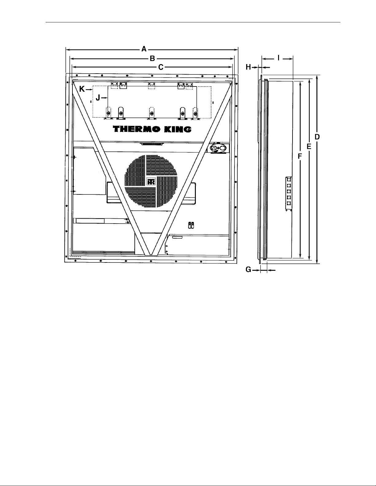
Specifications
Figure 2: Physical Specifications
AMA313
27
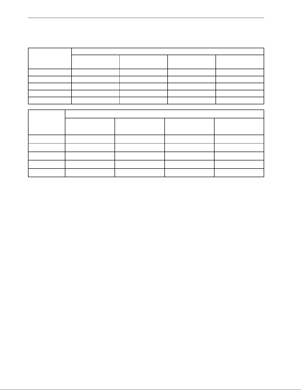
Specifications
Metric Hardware Torque Charts
Bolt Type
and Class*
HH – CL 5.8 6-9 (4-7) 12-16 (9-12) 27-34 (20-25) 48-61 (35-40)
HH – CL 8.8 10-13 (7-10) 20-27 (15-20) 41-47 (30-35) 75-88 (55-65)
HH – CL 10.9 14-17 (10-13) 27-34 (20-25) 54-68 (40-50) 102-122 (75-90)
HH – CL 12.9 17-21 (12-16) 41-47 (30-35) 68-81 (50-60) 122-149 (90-110)
HH – SS (2) 10-13 (7-10) 20-27 (15-20) 41-47 (30-35) 75-88 (55-65)
Bolt Type and
Class*
N.m (Ft.-lb.) N.m (Ft.-lb.) N.m (Ft.-lb.) N.m (Ft.-lb.)
HH – CL 5.8 75-88 (55-65) 115-135 (85-100) 177-216 (130-160) 339-406 (250-300)
HH – CL 8.8 115-135 (85-100) 177-216 (130-160) 271-339 (200-250) 475-610 (350-450)
HH – CL 10.9 136-176 (100-130) 224-298 (180-220) 393-474 (290-350) 678-813 (500-600)
HH – CL 12.9 177-216 (130-160) 285-352 (210-260) 448-542 (330-400) 881-1016 (650-750)
HH – SS (2) 115-135 (85-100) 177-216 (130-160) 271-339 (200-250) 475-610 (350-450)
*HH = Hex Head, CL = Class.
M6 M8 M10 M12
N.m (Ft.-lb.) N.m (Ft.-lb.) N.m (Ft.-lb.) N.m (Ft.-lb.)
M14 M16 M18 M22
Bolt Size
Bolt Size
28
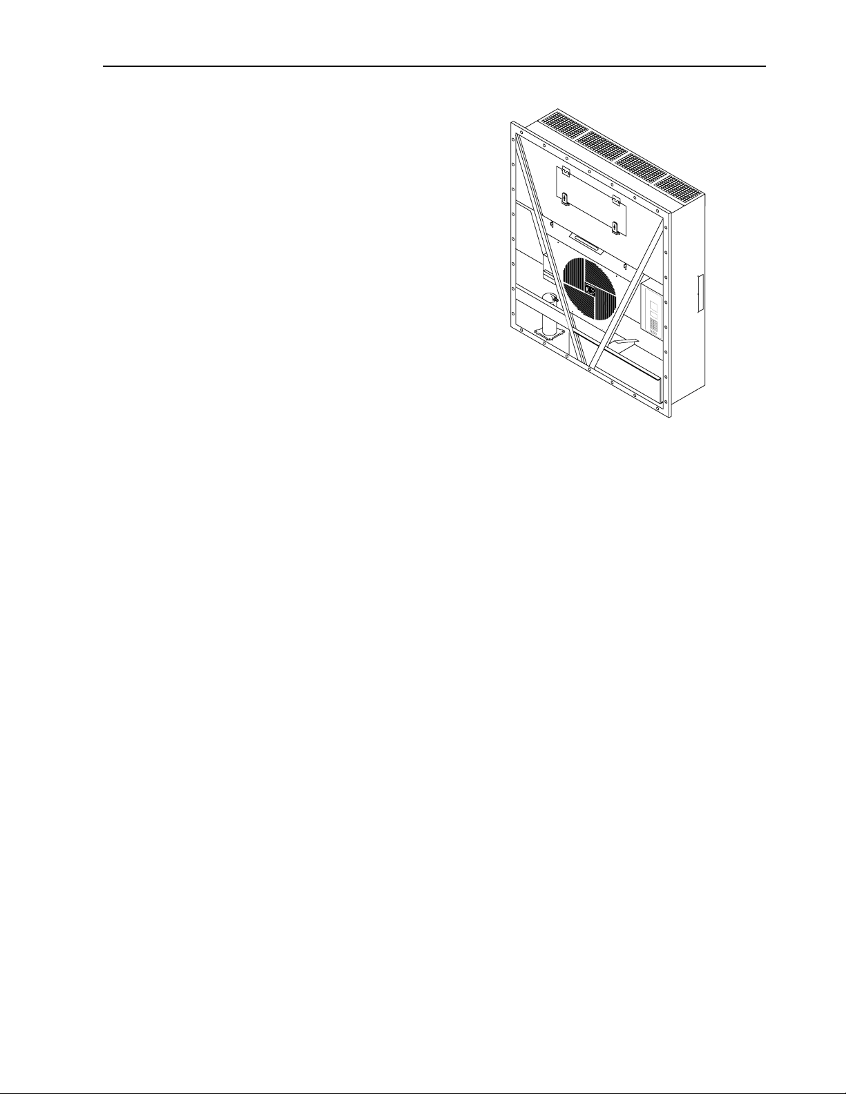
Unit Description, Features & Options
Introduction
This chapter will briefly describe the following
items:
• General Unit Description.
• Standar d Component Descriptions.
• Optional Component Descriptions.
General Description
MAGNUM units are all-electric, single-piece ,
refrigeration units with bottom air supply. The
unit is design ed to cool and heat containers for
shipboard or overland transit. The unit mounts in
the front wall of the container. MAGNUM SL and
MAGNUM 20 units feature a slimline frame.
Fork lift pockets are provided for installation and
removal of the unit.
Figure 3: MAGNUM Unit
AMA306
The frame and bulkhead panels are constructed of
aluminum and are treated to resist corrosion. A
hinged, removable evaporator compartment door
provides easy service access. All components
except the evaporator coil and electric heaters can
be replaced from the front of the unit.
Each unit is equipped with an 18.3 m (60 ft.)
power cable for ope ra t ion on 460-380V/3
Ph/60-50 Hz power. The unit power cable is
stored below the control box in the condenser
section.
Each unit is equipped with 460-380V/3 Ph/60-50
Hz electric motors. An automatic phase correction
system provides the proper electrical phase
sequence for condenser fan, evapo rator fan and
compressor operation.
The MAGNUM container unit features the
following components. Each component will be
described briefly on the following pages.:
• Scroll Compressor
• Compressor D igital Control Valve
• Economizer Heat Exc hange System
• Temperature Sensors
• Fresh Air Exchange System
• Receiver Tank Sight Glass
• Evaporato r Fans
• Condenser Fan Control
• Suction/Discharge Pressure Sensor (Optional)
• Remote Monitoring Receptacle Option (4-pin)
(optional)
• Remote Monitoring Modem ( RMM)
(Optional)
• USDA Cold Treatment Temperature
Recording (Opt ional)
• Water-Cooled Condenser/Receiver Tank
(Optional)
• Advanced Fresh Air Management (AFAM)
and Advanced Fresh Air Management Plus
(AFAM+) (Optional)
• Water Pressure Switch (Optional)
29
 Loading...