

Page 1

Maintenance Manual
CSR40-149 & -150
Power Saver
TK 50892-4-MM (Rev. 6/00)
Copyright ©2000, Thermo King Corporation, Minneapolis, MN, U.S.A.
Printed in U.S.A.
Page 2

This manual is published for informational purposes only and the information so provided should not be considered as all-inclusive
or covering all contingencies. If further information is required, Thermo King Corporation should be consulted.
Sale of product shown in this Manual is subject to Thermo King’s terms and conditions including, but not limited to, the THERMO
KING EXPRESS WARRANTY. Such terms and conditions are available upon request.
Thermo King’s warranty will not apply to any equipment which has been “so repaired or altered outside the manufacturer’s plants
as, in the manufacturer’s judgment, to effect its stability.”
No warranties, express or implied, including warranties of fitness for a particular purpose or merchantability, or warranties arising
from course of dealing or usage of trade, are made regarding the information, recommendations, and descriptions contained herein.
Manufacturer is not responsible and will not be held liable in contract or in tort (including negligence) for any special, indirect or consequential damages, including injury or damage caused to vehicles, contents or persons, by reason of the installation of any
Thermo King product or its mechanical failure.
SmartSponge and Thermoguard are trademarks of Thermo King Corporation. All other trademarks are the property of their respective owners.
Page 3

Recover Refrigerant
At Thermo King we recognize the need to preserve the environment and limit
the potential harm to the ozone layer that can result from allowing refrigerant
to escape into the atmosphere.
We strictly adhere to a policy that promotes the recovery and limits the loss
of refrigerant into the atmosphere.
In addition, service personnel must be aware of Federal regulations concerning the use of refrigerants and the certification of technicians. For additional
information on regulations and technician certification programs, contact
your local THERMO KING dealer.
Page 4

Page 5

Table of Contents
Introduction v
About This Manual v
Other Reference Manuals v
CSR40-149 & -150 PS Model Features vi
Safety Precautions vii
General Practices vii
Refrigerant vii
Refrigerant Oil viii
Electrical viii
General Safety Practices for Servicing Units
(or Containers) Equipped with a
Microprocessor Controller ix
Unit Decals x
Serial Number Locations x
Service Guide xi
Specifications 1-1
System Net Cooling Capacity — Full Cool:
CSR40 PS Models — Air Cooled Condensing 1-1
System Net Heating Capacity 1-1
Evaporator Airflow:
CSR40 PS Models 1-1
Electrical System 1-2
Refrigeration System 1-3
MP-3000 Controller 1-4
Dehumidify and Humidify Systems (Options) 1-5
Physical Specifications 1-6
Metric Hardware Torque Charts 1-7
Unit Description 2-1
Unit Features 2-1
Unit Options 2-2
Operating Modes 2-3
Unit Illustrations 2-4
Typical Unit Front View 2-4
Unit Options Front View 2-5
CSR40 PS Evaporator Section – Front View 2-6
Hermetic Refrigeration System 2-7
MP-3000 Controller 2-8
Unit Control Box 2-9
Humidify System Option 2-10
Advanced Fresh Air Management Option 2-11
Typical Unit Back View 2-12
Operating Instructions 3-1
Unit Controls 3-1
Unit Instruments 3-1
Unit Protection Devices 3-1
Pretrip Inspection 3-3
Starting the Unit and Adjusting the Controller
Setpoint 3-4
Loading Procedure 3-5
Post Load Procedure 3-5
Post Trip Procedure 3-5
MP-3000 Controller 4-1
Controller Description 4-1
Status Indicator LEDs 4-3
Data Recording and Downloading Data 4-3
General Theory of Operation 4-4
Chill Loads 4-4
Frozen Loads 4-5
Modulation Display in Data Menu 4-5
Power Limit Mode 4-5
CSR40-149 & -150 PS Hermetic, June 2000
Page 6

ii Table of Contents
Compressor Liquid Injection 4-5
Warm Gas Bypass 4-5
Evaporator Fan Control 4-5
Condenser Fan Control 4-6
Economy Mode Operation 4-6
Probe Test 4-6
Dehumidify Mode (Option) 4-7
Sequence of Operation 4-7
Unit Start-up 4-7
Continuous Temperature Control Operation 4-8
Operating Mode Function Chart — Standard
Operation 4-9
Operating Mode Function Chart — Optional
Feature Operation 4-10
Defrost 4-11
Changing the Setpoint 4-12
Initiating a Manual Defrost 4-12
Displaying Alternate Controlling (Supply or
Return) Air Sensor Temperature 4-12
Displaying Alternate Fahrenheit (F) or
Celsius (C) Temperatures 4-13
Navigating the Controller Menu 4-13
General Operating Tips 4-13
Setpoint Menu 4-13
Changing the Setpoint Temperature 4-13
Changing the Economy Mode Setting 4-14
Changing the Humidity Mode Setting 4-14
Changing the Humidity Setpoint 4-14
Changing the Advanced Fresh Air
Management (AFAM) Mode Setting 4-14
Changing the AFAM Delay 4-15
Changing the AFAM Rate 4-15
Data Menu 4-16
Viewing the Data Menu 4-16
Alarms Menu 4-16
Alarm Types 4-16
Alarm Code States 4-17
Viewing the Alarm List Menu 4-17
Alarm List 4-17
Commands Menu 4-18
View the Commands Menu 4-18
Defrost 4-19
Function Test 4-19
CSR PS Function Test Procedure 4-21
Pretrip (PTI) Test 4-20
CSR PS Pretrip (PTI) Test Procedure 4-23
Manual Function Test 4-20
Power Management 4-28
Misc. Functions Menu 4-28
Viewing the Misc. Functions Menu 4-28
Setting the Date and Time 4-28
Changing the Temperature Display
Value (C/F) 4-29
Setting Cargo Data 4-29
Viewing or Setting Run Time 4-30
Configuration Menu 4-30
Viewing or Setting Functions 4-30
Datalogger Menu 4-31
Viewing the Datalogger Menu 4-32
Inspect Temp Log 4-32
Inspect Event Log 4-32
Set Log Time 4-33
Set a Trip Start 4-33
Inspect PTI Log 4-34
RMM State Menu 4-34
Viewing the RMM State Screen 4-34
Manual Emergency Mode Operation 4-34
Replacing the Controller 4-35
Automatic Configuration of Spare
Parts Controller 4-35
Controller Software Selection 4-36
Flash Loading Controller Software 4-36
Temperature Sensors 4-36
Diagnosis and Repair 4-38
Error Messages and Controller Actions 4-39
Alarm Codes, Descriptions and
Corrective Actions 4-42 to 4-61
Electrical Maintenance 5-1
Unit Wiring 5-1
High Pressure Cutout Switch 5-1
Low Pressure Cutout Switch 5-2
Condenser Fan and Evaporator Fan Rotation 5-2
Electric Heaters 5-3
CSR40-149 & -150 PS Hermetic, June 2000
Page 7

Table of Contents iii
Refrigeration System Diagnosis and Service 6-1
Hermetic Refrigeration System Diagnosis
Procedures 6-1
Hermetic Refrigeration System Visual Inspection
and Diagnosis Chart 6-3
Hermetic Refrigeration System Service
Procedures 6-4
Service Tools 6-4
Refrigerant Charge 6-5
Compressor Oil Charge 6-6
Installing and Removing Piercing Type Service
Valves and a Gauge Manifold Set 6-6
Gauge Manifold Valve Positions 6-8
Refrigerant Leak Test Procedure 6-9
Using Pressurized Nitrogen 6-9
Refrigerant Recovery from Hermetic
Refrigeration Systems 6-10
Evacuation and Cleanup of the
Refrigeration System 6-11
Charging the System with Refrigerant 6-15
Compressor Replacement 6-15
Compressor Discharge Temperature Sensor
Replacement 6-16
Stepper Motor Valve Replacement 6-17
Condenser Coil Replacement 6-17
Filter Drier/In-line Filter Replacement 6-18
Expansion Valve Replacement 6-18
Heat Exchanger Replacement 6-19
Receiver Tank Replacement 6-19
Low or High Pressure Cutout Switch Replacement 6-20
Warm Gas Bypass Solenoid Valve, Liquid
Injection Valve or Dehumidify Valve
(Option) Replacement 6-20
Structural/Accessory Maintenance 7-1
Mounting Bolts 7-1
Unit Inspection 7-1
Condenser Coil 7-1
Evaporator Coil 7-1
Defrost Drains 7-2
Condenser Fan Location 7-2
Evaporator Fan Location 7-2
Humidify System (Option) 7-2
Partlow (Model SR) Recording Thermometer
(Option) 7-3
Advanced Fresh Air Management (AFAM) System
(Option) 7-5
Mechanical Diagnosis 8-1
Mechanical Diagnosis 8-1
Electrical, Refrigeration and MP-3000 Menu Flow
Diagrams 9-1
Controller Diagram 9-3
Wiring Schematic 9-4
Main Relay Board Terminal Connections
(Page 1 of 3) 9-5
Main Relay Board Terminal Connections
(Page 2 of 3) 9-6
Main Relay Board Terminal Connections
(Page 3 of 3) 9-7
Refrigeration System Schematics:
Refrigeration System Components 9-8
Full Cool Flow and Pressure Diagram 9-9
Modulation Cool Flow and Pressure Diagram 9-10
Dehumidification Flow and Pressure Diagram 9-11
MP-3000 Menu Flow Diagram 9-12
CSR40-149 & -150 PS Hermetic, June 2000
Page 8

Page 9

Introduction
About This Manual
The information in this manual is provided to assist owners,
operators and service people in the proper upkeep and maintenance of Thermo King units. This manual includes maintenance and diagnosis information for both standard and optional unit features. Some optional features may not apply to your
unit. The maintenance information in this manual covers unit
models:
CSR PS Hermetic Models System Number
CSR40-149 Power Saver 917149
CSR40-150 Power Saver 917150
Other Reference Manuals
For detailed descriptions of our refrigeration systems or microprocessor controllers, see the appropriate manual. For further
information refer to:
Operation, Diagnosis and Refrigeration Maintenance
Manuals
Diagnosing Thermo King Container
Refrigeration Systems TK 41166
Electrostatic Discharge (ESD)
Training Guide TK 40282
Evacuation Station Operation and Field
Application TK 40612
Tool Catalog TK 5955
CSR40-149 & -150 PS Hermetic, June 2000
Page 10
vi CSR40-149 & -150 PS Model Features Introduction
CSR40-149 & -150 PS Model Features
MODEL
FEATURES
CSR40-149 PS
CSR40-150 PS
– – Slimline Frame
X X Top Air Discharge
X X 460-380V/3Ph/60-50 Hz, 18.3 m (60 ft) Power Cable and Plug
X X Dual Voltage Feature: 15 kVA Autotransformer with 460-380V Power Receptacle and 230-190V/3Ph/60-50 Hz, 18.3 m
(60 ft) Power Cable and Plug
X X 25 Amp Main Power Circuit Breaker
X X Automatic Phase Selection Control
X X Hermetic Scroll Compressor w/4.48 kW (6.0 Hp) Motor
X X Hermetic Refrigeration System
X X Refrigerant R-404A w/Polyol Ester Compressor Oil (TK P/N 203-433)
X X Stepper Valve Capacity Control System
X X Compressor Liquid Injection System
X X Warm Gas Bypass Valve System
X X MP-3000 Microprocessor Controller with Integral Datalogger
– – Three (3) Evaporator Fans with 2-Speed Motors
X X Two (2) Evaporator Fans with 2-Speed Motors
X X Condenser Fan with 1-Speed Motor
– – Fresh Air Exchange System
X X AFAM — Advanced Fresh Air Management
– – Data Retrieval Receptacle, Standard (5-Pin Deutsch)
X X Data Retrieval Receptacle, 5-Pin Threaded Cannon
– – Data Retrieval Receptacle, 15-Pin RS232
– X Dehumidify Control
– X Humidity System
– – Pressure Gauge, Discharge
– – Pressure Gauge, Suction
X X Recorder, Partlow
– – Recorder, Saginomiya
– – Remote Monitoring Plug (4-Pin)
®
– – TRANSFRESH
– – TRANSFRESH
– – TRANSFRESH
Provision
®
Purge Port
®
System, Complete
– – Thermistor Lead
– – USDA Cold Treatment Temperature Recording
– – Water-Cooled Condenser-Receiver Tank
X = Included
CSR40-149 & -150 PS Hermetic, June 2000
Page 11

Safety Precautions
General Practices
1. ALWAYS WEAR GOGGLES OR SAFETY GLASSES.
Refrigerant liquid and battery acid can permanently damage the eyes (see First Aid under Refrigerant Oil).
2. Never close the compressor discharge valve with the unit
in operation. Never operate the unit with the discharge
valve closed.
3. Keep your hands, clothing and tools clear of the fans
when the refrigeration unit is running. If it is necessary to
run the refrigeration unit with covers removed, be very
careful with tools or meters being used in the area.
4. Be sure the gauge manifold hoses are in good condition.
Never let them come in contact with a fan motor blade or
any hot surface.
5. Never apply heat to a sealed refrigeration system or container.
6. Fluorocarbon refrigerants, in the presence of an open
flame or electrical arc, produce toxic gases that are severe
respiratory irritants capable of causing death.
7. Be sure all mounting bolts are tight and are the correct
length for their particular application.
8. Use extreme caution when drilling holes in the unit. The
holes may weaken structural components. Holes drilled into
electrical wiring can cause fire or explosion. Holes drilled
into the refrigeration system may release refrigerant.
9. Use caution when working around exposed coil fins. The
fins can cause painful lacerations.
10. Use caution when working with a refrigerant or refrigeration system in any closed or confined area with a limited
air supply (for example, a trailer, container or in the hold
of a ship). Refrigerant tends to displace air and can cause
oxygen depletion, resulting in suffocation and possible
death.
11. Use caution and follow the manufacturer’s suggested
practices when using ladders or scaffolds.
Refrigerant
When removing any refrigerant from a unit, use a recovery
process that prevents or absolutely minimizes the refrigerant
that can escape to the atmosphere. Although fluorocarbon
refrigerants are classified as safe refrigerants when proper
tools and procedures are used, certain precautions must be
observed when handling them or servicing a unit in which they
are used. When exposed to the atmosphere in the liquid state,
fluorocarbon refrigerants evaporate rapidly, freezing anything
they contact.
First Aid
In the event of frost bite, the objectives of First Aid are to protect the frozen area from further injury, to warm the affected
area rapidly, and to maintain respiration.
• EYES: For contact with liquid, immediately flush eyes
with large amounts of water and get prompt medical attention.
• SKIN: Flush area with large amounts of lukewarm water.
Do not apply heat. Remove contaminated clothing and
shoes. Wrap burns with dry, sterile, bulky dressing to
protect from infection/injury. Get medical attention.
Wash contaminated clothing before reuse.
• INHALATION: Move victim to fresh air and use CPR or
mouth-to-mouth ventilation, if necessary. Stay with victim
until arrival of emergency medical personnel.
CSR40-149 & -150 PS Hermetic, June 2000
Page 12

viii Refrigerant Oil Safety Precautions
4. Do not make any rapid moves when working on high volt-
Refrigerant Oil
Observe the following precautions when working with or
around refrigerant oil:
• Do not allow refrigerant oil to contact your eyes.
• Do not allow prolonged or repeated contact with skin or
clothing.
• To prevent irritation, you should wash thoroughly immediately after handling refrigerant oil. Rubber gloves are
recommended when handling Polyol Ester based refrigerant oil.
First Aid
• EYES: Immediately flush eyes with large amounts of
water for at least 15 minutes while holding the eyelids
open. Get prompt medical attention.
• SKIN: Remove contaminated clothing. Wash thoroughly
with soap and water. Get medical attention if irritation
persists.
• INHALATION: Move victim to fresh air and restore
breathing if necessary. Stay with victim until arrival of
emergency personnel.
• INGESTION: Do not induce vomiting. Contact a local
poison control center or physician immediately.
Electrical
High Voltage
When servicing or repairing a refrigeration unit, the possibility
of serious or even fatal injury from electrical shock exists.
Extreme care must be used when working with a refrigeration
unit that is connected to a source of operating power, even if
the unit is not running. Lethal voltage potentials can exist at
the unit power cord, inside the control box, inside any high
voltage junction box, at the motors and within the wiring harnesses.
Precautions
1. Be certain the unit On/Off switch is turned OFF before
connecting or disconnecting the unit power plug. Never
attempt to stop the unit by disconnecting the power plug.
2. Be certain the unit power plug is clean and dry before
connecting it to a power source.
3. Use tools with insulated handles that are in good condition. Never hold metal tools in your hand if exposed,
energized conductors are within reach.
age circuits. If a tool or other object falls, do not attempt
to grab it. People do not contact high voltage wires on
purpose. It occurs from an unplanned movement.
5. Treat all wires and connections as high voltage until a
meter and wiring diagram show otherwise.
6. Never work alone on high voltage circuits on the refrigeration unit. Another person should always be standing by
in the event of an accident to shut off the refrigeration unit
and to aid a victim.
7. Have electrically insulated gloves, cable cutters and safety
glasses available in the immediate vicinity in the event of
an accident.
First Aid
IMMEDIATE action must be initiated after a person has
received an electrical shock. Obtain immediate medical assistance if available.
The source of shock must be immediately removed by
either shutting down the power or removing the victim from
the source. If it is not possible to shut off the power, the wire
should be cut with either an insulated instrument (e.g., a wooden handled axe or cable cutters with heavy insulated handles)
or by a rescuer wearing electrically insulated gloves and safety
glasses. Whichever method is used, do not look at the wire
while it is being cut. The ensuing flash can cause burns and
blindness.
If the victim has to be removed from a live circuit, pull the
victim off with a non-conductive material. Use the victim’s
coat, a rope, wood, or loop your belt around the victim’s leg or
arm and pull the victim off. DO NOT TOUCH the victim.
You can receive a shock from current flowing through the victim’s body.
After separating the victim from power source, check
immediately for the presence of a pulse and respiration. If a
pulse is not present, start CPR (Cardio Pulmonary
Resuscitation) and call for emergency medical assistance. If a
pulse is present, respiration may be restored by using mouthto-mouth resuscitation, but call for emergency medical assistance.
Low Voltage
Control circuits are low voltage (24 Vac and 12 Vdc). This
voltage potential is not considered dangerous, but the large
amount of current available (over 30 amperes) can cause
severe burns if shorted to ground.
Do not wear jewelry, watch or rings. These items can short
out electrical circuits and cause severe burns to the wearer.
CSR40-149 & -150 PS Hermetic, June 2000
Page 13

Safety Precautions General Safety Precautions for Servicing Controllers ix
Welding of Units or Containers
General Safety Precautions for Servicing
Units (or Containers) Equipped with a
Microprocessor Controller
Precautions must be taken to prevent electrostatic discharge
when servicing the MP-3000 microprocessor and related components. If these precautionary measures are not followed, the
risk of significant damage to the electronic components of the
unit is possible.
The primary risk potential results from the failure to wear
adequate electrostatic discharge preventive equipment when
handling and servicing the controller. The second cause
results from electric welding on the unit and container chassis
without taking precautionary steps.
Controller Repair
When servicing the controller, it is necessary to ensure that
electrostatic discharges are avoided. Potential differences considerably lower than those which produce a small spark from a
finger to a door knob can severely damage or destroy solidstate integrated circuit components. The following procedures
must be rigidly adhered to when servicing these units to avoid
controller damage or destruction.
1. Disconnect all power to the unit.
2. Avoid wearing clothing that generates static electricity
(wool, nylon, polyester, etc.).
3. Do wear a static discharge wrist strap (TK P/N 204-622)
with the lead end connected to the controller's ground ter-
minal. These straps are available at most electronic equip-
ment distributors. DO NOT wear these straps with power
applied to the unit.
4. Avoid contacting the electronic components on the circuit
boards of the unit being serviced.
5. Leave the circuit boards in their static proof packing mate-
rials until ready for installation.
6. If a defective controller is to be returned for repair, it
should be returned in the same static protective packing
materials from which the replacement component was
removed.
7. After servicing the circuit board and any other circuits, the
wiring should be checked for possible errors before restor-
ing power.
Whenever electric welding is to be performed on any portion
of the refrigeration unit, container or container chassis with the
refrigeration unit attached, it is necessary to ensure that welding currents are NOT allowed to flow through the electronic
circuits of the unit. These procedures must be rigidly adhered
to when servicing these units to avoid damage or destruction.
1. Disconnect all power to the refrigeration unit.
2. Disconnect all quick-disconnect wire harnesses from the
back of the controller.
3. If the unit is equipped with an Remote Monitor Modem
(RMM), disconnect all wire harnesses from the RMM.
4. Switch all of the electrical circuit breakers in the control
box to the OFF position.
5. Weld unit and/or container per normal welding procedures. Keep ground return electrode as close to the area to
be welded as practical. This will reduce the likelihood of
stray welding currents passing through any electrical or
electronic circuits.
6. When the welding operation is completed, the unit power
cables, wiring and circuit breakers must be restored to
their normal condition.
CSR40-149 & -150 PS Hermetic, June 2000
Page 14
x Unit Decals Safety Precautions
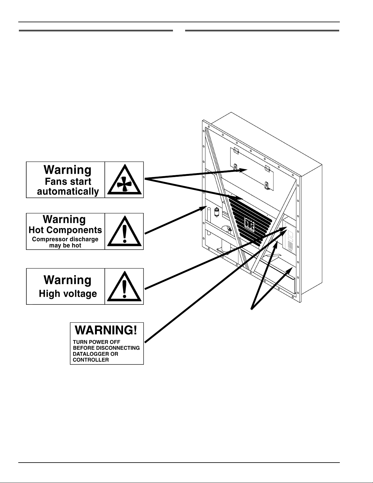
Unit Decals
Serial number decals, refrigerant type decals and warning
decals appear on all Thermo King equipment. These decals
provide information that may be needed to service or repair the
unit. Service technicians should read and follow the instructions on all warning decals.
Serial Number Locations
Electric Motors: Nameplate attached to the motor housing.
Compressor: Nameplate on front of the compressor.
Unit: Nameplate on unit frame in power cord storage compart-
ment.
MP-3000 Controller: Nameplate on back of controller.
Unit Nameplate Location
CSR40-149 & -150 PS Hermetic, June 2000
Page 15
Service Guide
Every Annual/
1,000 Yearly
Pretrip Hours Inspect/Service These Items
Refrigeration
• Perform a controller Pretrip Inspection (PTI) test to check the refrigeration and electri-
cal systems.
Electrical
•••Visually inspect condenser fan and evaporator fan rotation.
•••Visually inspect electrical contacts for damage or loose connections.
•••Visually inspect wire harnesses for damaged wires or connections.
••
•
Download the data logger and check data for correct logging.
Check operation of protection shutdown circuits.
Structural
•••
•••
••
•
•••
••
Visually inspect unit for damaged, loose or broken parts.
Tighten unit, compressor and fan motor mounting bolts.
Clean entire unit including condenser and evaporator coils and defrost drains.
Humidify System (Option)
Check water level in water tank.
Check humidify system operation.
Clean water supply filter on water tank.
CSR40-149 & -150 PS Hermetic, June 2000
Page 16

Page 17
1 Specifications
System Net Cooling Capacity — Full Cool
CSR40 PS Models — Air Cooled Condensing*
Return air to 460/230V, 3 Phase, 60 Hz Power 380/190V, 3 Phase, 50 Hz Power
evaporator Net Cooling Capacity Power Consp Net Cooling Capacity Power Consp
coil inlet Watts Kcal/hr BTU/hr kW @460V Watts Kcal/hr BTU/hr kW @380V
21.1 C (70 F) 13,660 11,750 46,620 9.7 10,930 9,400 37,300 7.6
1.7 C (35 F) 10,090 8,680 34,440 8.9 8,070 6,940 27,545 6.9
-17.8 C (0 F) 5,945 5,115 20,290 6.0 4,755 4,090 16,230 5.4
-28.9 C (-20 F) 4,000 3,440 13,650 5.6 3,200 2,750 10,920 4.1
*System net cooling capacity with a 37.8 C (100 F) ambient air temperature and R-404A.
System Net Heating Capacity*
Heater Type 460/230V, 3 Phase, 60 Hz Power 380/190V, 3 Phase, 50 Hz Power
Heating Capacity Heating Capacity
Watts Kcal/hr BTU/hr Watts Kcal/hr BTU/hr
CSR40 PS 5,800 4,990 19,800 4,200 3,610 14,335
*System net heating capacity includes electric resistance rods and fan heat.
Evaporator Airflow
CSR40 PS Models
External Static 460/230V, 3 Phase, 60 Hz Power 380/190V, 3 Phase, 50 Hz Power
Pressure (water High Speed Low Speed High Speed Low Speed
column) m3/hr ft3/min m3/hr ft3/min m3/hr ft3/min m3/hr ft3/min
0 mm (0 in.) 6,560 3,860 3,170 1,865 5,480 3,225 2,710 1,595
10 mm (0.4 in.) 5,820 3,425 1,770 1,040 4,530 2,665 930 545
20 mm (0.8 in.) 5,000 2,940 — — 3,750 2,205 — —
30 mm (1.2 in.) 4,430 2,610 — — 2,930 1,725 — —
40 mm (1.6 in.) 3,520 2,070 — — 1,870 1,100 — —
CSR40-149 & -150 PS Hermetic, June 2000
Page 18

1-2 Electrical System Specifications
Electrical System
Compressor Motor: Type 460/380V, 60/50 Hz, 3 Phase
Kilowatts 4.48 kW @ 460V, 60 Hz
Horsepower 6.0 hp @ 460V, 60 Hz
RPM 3550 rpm @ 460V, 60 Hz
Locked Rotor Amps 70 amps @ 460V, 60 Hz
Condenser Fan Motor: Type 460/380V, 60/50 Hz, 3 Phase
Kilowatts 0.37 kW @ 460V, 60 Hz
Horsepower 0.50 hp @ 460V, 60 Hz
RPM 1140 rpm @ 460V, 60 Hz
Full Load Amps 1.0 amps @ 460V, 60 Hz; 1.0 amps @ 380V, 50 Hz
Locked Rotor Amps 4.0 amps @ 460V, 60 Hz; 4.0 amps @ 380V, 50 Hz
Evaporator Fan Motors: Type 460/380V, 60/50 Hz, 3 Phase
Number: CSR40 PS 2
Kilowatts 0.75 kW @ 460V, 60 Hz
Horsepower 1.0 hp @ 460V, 60 Hz
RPM (Each): High Speed 3450 rpm @ 460V, 60 Hz
Low Speed 1725 rpm @ 460V, 60 Hz
Full Load Amps (Each): High Speed 1.1 amps @ 460V, 60 Hz
Low Speed 0.55 amps @ 460V, 60 Hz
Locked Rotor Amps: High Speed 10.3 amps @ 460V, 60 Hz
Low Speed 2.9 amps @ 460V, 60 Hz
Electric Resistance Heater Rods: Type 460/380V, 60/50 Hz, 3 Phase
Number 6
Watts (Each) 680 Watts @ 460V, 60 Hz
Current Draw (Amps) 5 amps total @ 460V across each phase at heater contactor
Control Circuit Voltage: 29 Vac @ 60 Hz
24 Vac @ 50 Hz
Advanced Fresh Air Management (AFAM) Motor:
Voltage 24 Vdc
Evaporator Overheat Switch: Opens 54 +/- 3 C (130 +/- 5 F)
Closes 38 +/- 4.5 C (100 +/- 8 F)
CSR40-149 & -150 PS Hermetic, June 2000
Page 19
Specifications Refrigeration System 1-3
Refrigeration System
Compressor Model No.: ZM18K4E-TFD-279, Hermetic Scroll
Refrigerant Charge: CSR40 PS 3.6 Kg (8.0 lb) R-404A
Compressor Oil Capacity 1.77 liter (60 oz.)*
Compressor Oil Type Polyol Ester Based Type (required), TK Part No. 203-433**
High Pressure Cutout Switch: Cutout 3243 +/- 48 kPa, 32.43 +/- 0.48 bar, 470 +/- 7 psig
Cutin 2588 +/- 262 kPa, 25.88 +/- 2.62 bar, 375 +/- 38 psig
Low Pressure Cutout Switch: Cutout +21 to -20 kPa, +0.21 to -0.20 bar, 3 psig to 6” Hg vacuum
Cutin 48 to 90 kPa, 0.48 to 0.90 bar, 7 to 13 psig
High Pressure Relief Valve: Relief Pressure 3447 +520/-104 kPa, 34.47 +5.20/-1.04 bar, 500 +75/-15 psig
Reset 2758 kPa, 27.58 bar, 400 psig
Liquid Injection Control: Compressor Start Liquid injection valve opens for 5 minutes on each compressor start
Power Limit or Modulation Cool Liquid injection valve opens continuously during Power Limit and
Modulation Cool modes
Compressor Discharge Temperature Control Energizes (Opens) Liquid Injection Valve at 138 C (280 F)
De-energizes (Closes) Liquid Injection Valve at 132 C (270 F)
Compressor Shutdown (Auto Reset) at 148 C (298 F)
Liquid Injection Valve (Compressor): Voltage 24 Vac
Current 0.85 amps
Cold Resistance 5.6 ohms
Warm Gas Bypass Solenoid Valve: Voltage 24 Vac
Current 0.85 amps
Cold Resistance 5.6 ohms
Stepper Valve Regulating Motor: Voltage 12 Vdc
Current Draw 0.13 to 0.21 amperes per winding
0.26 to 0.44 amperes with 2 windings energized
Resistance 75 +/- 7.5 ohms across each winding at 24 C (75 F) ambient
*When the compressor is removed from the unit, oil level should be noted or the oil removed from the compressor should be mea-
sured so that the same amount of oil can be maintained in the replacement compressor.
**DO NOT use or add standard synthetic or mineral oils to the refrigeration system. If Ester based oil becomes contaminated with
moisture or with standard oils, dispose of properly — DO NOT USE!
CSR40-149 & -150 PS Hermetic, June 2000
Page 20

1-4 MP-3000 Controller Specifications
MP-3000 Controller
Temperature Controller: Type MP-3000 microprocessor with thermostat, digital thermometer, pro-
gramming keypad, mode indicators, LED display and LCD display
for displaying unit operating and cargo information
Setpoint Range -29.0 to +29.0 C (-20.2 to +84.2 F)
Digital Temperature Display -60.0 to +80.0 C (-76.0 to +176.0 F)
Controller Software (Original Equipment): Version See controller identification decal
Defrost Initiation Evaporator Coil Sensor - Manual Switch or Demand Defrost Initiation: Coil must be below
18 C (65 F). Defrost cycle starts when technician or controller
request defrost initiation.
- Timed Defrost Initiation: Coil must be below 10 C (50 F).
Defrost cycle starts 1 minute after the hour immediately following
a defrost timer request for defrost initiation. For example, if the
defrost timer requests a defrost cycle at 7:35, the defrost cycle will
start at 8:01. Datalogger will record a Defrost event for each inter-
val in which a Defrost cycle is pending or active (i.e. both the 8:00
and 9:00 data logs).
Demand Defrost Demand defrost function initiates defrost when:
- Temperature difference between the return air sensor and defrost
(evaporator coil) sensor is too large
- Temperature difference between the supply air sensor and return
air sensor is too large
Defrost Timer: Chilled mode - Supply Temperature at 5.1 C (41.2 F) or Above: Every 8 hours of
compressor operation.
- Supply Temperature at 5.0 C (41.0 F) or Below: Every 2.5 hours
of compressor operation. Defrost interval increases 0.5 hours each
timed defrost interval. Defrost synchronization creates step inter-
vals of 3, 4, 4, 5, 5, 6, 6 and 7 hours. Maximum time interval in
chilled mode is 7 hours.
Defrost Timer: Frozen mode Every 8 hours of compressor operation. Defrost interval increases 2
hours each timed defrost interval. Maximum time interval in frozen
mode is 24 hours.
Defrost Timer: Reset to Base Time Defrost timer resets if the unit is Off more than 12 hours, setpoint is
changed more than 5 C (9 F) or PTI Pretrip test occurs.
CSR40-149 & -150 PS Hermetic, June 2000
Page 21

Specifications Dehumidify and Humidify Systems 1-5
MP-3000 Controller (Continued)
Defrost Termination: Defrost (Coil) Sensor Chilled mode: Terminates defrost when coil sensor temperature
rises to 30 C (86 F); or exceeds 18 C (65 F) for 15
minutes
Frozen mode: Terminates defrost when coil sensor temperature
rises to 18 C (65 F); or exceeds 8 C (46 F) for 15
minutes
Termination Timer Terminates defrost after 90 minutes at 60 HZ operation if coil sen-
sor has not terminated defrost (120 minutes at 50 Hz operation)
Power Off Turning unit On/Off switch OFF terminates defrost
Compressor Shutdown Protection (Auto Reset):
Stops Compressor 130 C (266 F)
Allows Compressor Start 90 C (194 F)
Dehumidify and Humidify Systems (Options)
Dehumidify System (Option):
Turn Mode ON and OFF Set from CONTROL line of the Setpoint menu of the controller
Control Range (HUMSP) Setting 50% to 99% Relative Humidity
Humidify System (Option): Turn Mode ON and OFF Set from CONTROL line of the Setpoint menu of the controller
Operating Temperature Range 0 to 60 C (32 to 140 F)
Control Range (HUMSP) Setting 50% to 99% Relative Humidity
Air Compressor Output 2.5 m3/hr @ 0 kPa (1.5 CFM @ 0 psig)
Humidity Tank Heater: 240-600 Vac; 55 to 70 Watts at -17.8 C (0 F) Water Temperature
Humidity Sensor: Accuracy: +/- 1.5% between 55% and 75% Relative Humidity
+/- 3.0% between 75% and 95% Relative Humidity
Output Range: 4 to 20 milliamps
1% Relative Humidity = 0.2 milliamp
CSR40-149 & -150 PS Hermetic, June 2000
Page 22
1-6 Physical Specifications Specifications
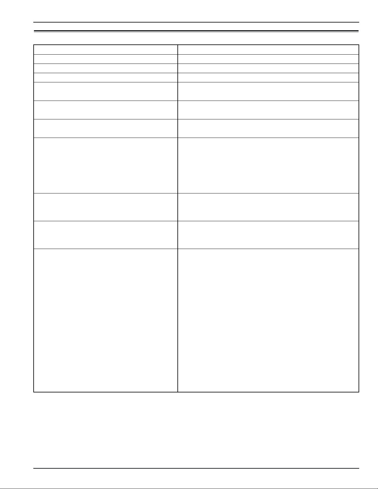
Physical Specifications
Advanced Fresh Air Management (AFAM)
Exchange Rate: CSR40 PS 0 to 285 m3/hr (0 to 168 ft3/min.) @ 60 Hz
0 to 236 m3/hr (0 to 139 ft3/min.) @ 50 Hz
Evaporator Fan Blade Specifications:
CSR40 PS Top Air Discharge: Diameter 355 mm (14.0 in.)
Pitch 25
Number 2
Weight (net): CSR40 PS Base Unit 413 Kg (910 lb)
Dual Voltage Option 45 Kg (99 lb)
Power Line Communications Option 3.6 Kg (8 lb)
Recorder (Partlow or Saginomiya) Option 5.9 Kg (13 lb)
Full TRANSFRESH®Option 13 Kg (28 lb)
Unit Dimensions: A = Flange Width 2025.5 mm (79.74 in.)
B = Gasket Width 1935 mm (76.18 in.)
C = Unit Width 1894 mm (74.57 in.)
D = Flange Height 2235.2 mm (88.00 in.)
E = Gasket Height 2140 mm (84.25 in.)
F = Unit Height 2094 mm (82.44 in.)
G = Gasket Depth 72 mm (2.83 in.) from back of flange
H = Maximum Protrusion 37 mm (1.46 in.) from back of flange
I = Unit Depth: CSR40 PS 420.0 mm (16.54 in.) from back of flange
o
CSR40-149 & -150 PS Hermetic, June 2000
Page 23
Specifications Metric Hardware Torque Charts 1-7
Metric Hardware Torque Charts
Bolt Size
Bolt Type M6 M8 M10 M12
and Class* N.m (Ft.-lb.) N.m (Ft.-lb.) N.m (Ft.-lb.) N.m (Ft.-lb.)
HH – CL 5.8 6-9 (4-7) 12-16 (9-12) 27-34 (20-25) 48-61 (35-40)
HH – CL 8.8 10-13 (7-10) 20-27 (15-20) 41-47 (30-35) 75-88 (55-65)
HH – CL 10.9 14-17 (10-13) 27-34 (20-25) 54-68 (40-50) 102-122 (75-90)
HH – CL 12.9 17-21 (12-16) 41-47 (30-35) 68-81 (50-60) 122-149 (90-110)
HH – SS (2) 10-13 (7-10) 20-27 (15-20) 41-47 (30-35) 75-88 (55-65)
Bolt Size
Bolt Type M14 M16 M18 M22
and Class* N.m (Ft.-lb.) N.m (Ft.-lb.) N.m (Ft.-lb.) N.m (Ft.-lb.)
HH – CL 5.8 75-88 (55-65) 115-135 (85-100) 177-216 (130-160) 339-406 (250-300)
HH – CL 8.8 115-135 (85-100) 177-216 (130-160) 271-339 (200-250) 475-610 (350-450)
HH – CL 10.9 136-176 (100-130) 224-298 (180-220) 393-474 (290-350) 678- 813 (500-600)
HH – CL 12.9 177-216 (130-160) 285-352 (210-260) 448-542 (330-400) 881-1016 (650-750)
HH – SS (2) 115-135 (85-100) 177-216 (130-160) 271-339 (200-250) 475-610 (350-450)
*HH = Hex Head, CL = Class.
CSR40-149 & -150 PS Hermetic, June 2000
Page 24

Page 25

2 Unit Description
Dual Speed Evaporator Fans
Unit Features
Model CSR40-149 & -150 PS units are all-electric, singlepiece, refrigeration units with top air supply. Each unit is
designed to cool and heat containers for shipboard or overland
transit. Each unit mounts in the front wall of the container.
Fork lift pockets are provided for installation and removal of
the unit.
The frame and bulkhead panels are constructed of aluminum and are treated to resist corrosion. A hinged, removable evaporator compartment door provides easy service
access. All operating components except the evaporator coil
and electric heaters can be replaced from the front of the unit.
A totally sealed, hermetic refrigeration system minimizes
maintenance and service.
Each unit is equipped with an 18.3 m (60 ft) power cable
for operation on 460-380V/3 Ph/60-50 Hz power. For operation on 460-380V/3 Ph/60-50 Hz power, plug the 460-380V
power cable into the proper power supply. The unit power
cable is stored below the control box in the condenser section.
Each unit is equipped with 460-380V/3 Ph/60-50 Hz electric motors. An automatic phase correction system provides
the proper electrical phase sequence for condenser fan, evaporator fan and compressor operation.
Unit features include a hermetic scroll compressor with a
liquid injection system; 2-speed evaporator fans; a fresh air
exchange system; and a MP-3000 controller with integral data
logger. For additional unit feature information, see “CSR40149 & -150 PS Model Features” on page vi of the
Introduction.
Hermetic Scroll Compressor with Liquid Injection
Cooling System
The refrigeration unit includes a hermetic scroll compressor
(one stationary and one orbiting member) with ambient compensated internal overload and high temperature protectors,
and a refrigerant injection system.
CSR PS models are equipped with either 2 or 3 evaporator fans.
All models feature 2-speed motors. The evaporator fans operate
continuously to circulate air inside the container. The fans operate on high speed for perishable cargo at setpoints of -9.9 C
(14.1 F) and above. At setpoints of -10 C (14 F) and below, the
evaporator fans operate on low speed for frozen cargo.
NOTE: If Economy Mode is ON:
• Fresh Loads: Evaporator fans operate on low
speed when container temperature is in-range.
• Frozen Loads: Evaporator fans stop during the
Null mode; controller operates fans on low speed
for 5 minutes every 45 minutes.
Fresh Air Exchange System
The fresh air exchange system removes harmful gases from
containers carrying sensitive perishable commodities. The
fresh air vent is located above the control box. The fresh air
vent is adjustable to accommodate a variety of cargo and
chilled load operating conditions. The fresh air vent should be
tightly closed when carrying frozen cargo.
MP-3000 Controller
The MP-3000 controller incorporates refrigeration system
component control, thermostat, digital thermometer, fault indication and data recording capabilities into one self-contained
package.
The controller mounts in a weather tight, corrosion resistance enclosure. A large-character LED display (top) provides
easy viewing of the control sensor temperature (return or supply air temperature). A 4-line, 20-character LCD display (bottom) display shows important data including the setpoint temperature, controller Main Menu tree and important unit operating data.
CSR40-149 & -150 PS Hermetic, June 2000
Page 26

2-2 Unit Options Unit Description
Sixteen general purpose keys are used to enter and scroll
through the controller menu tree and message text; initiate
Pretrip and Function tests; enter new setpoint temperature; and
enter trip information. The keyboard supports both numerical
and text input. Four special keys provide quick access to setpoint temperature change, manual defrost initiation, alternate
return/supply air temperature display, and alternate temperature scale (C/F) display.
Status indicator LEDs in the controller display signal
Compressor, Heat, Defrost, In-range, Alarm, Humidity,
Supply Temperature display and Return Temperature display.
A datalogger incorporated in the MP-3000 controller
records sensor temperatures as well as loss of power, alarms,
unit operating modes, sensor failure, setpoint change and unit
shutdown indications. All data recordings are stored in a
RAM memory that is backed by battery.
Logging intervals are selectable from 1 minute and 1/2, 1,
2 or 4 hours. When a 1 hour logging interval is selected, the
datalogger memory can store approximately 680 days of information. The logging of USDA sensors is fixed at 1 hour intervals to comply with USDA requirements.
The datalogger clock is factory set at UTC time. All data
logs include the time and date; setpoint temperature; and supply, return, USDA1, USDA2 and USDA3 sensor temperatures.
All temperature logs can be viewed from the controller’s LCD
message display.
A high speed serial communication port provides data
retrieval using a DRU-II hand-held data retriever or laptop
computer with SmartSponge software, or a REFCON power
line remote monitoring system.
Unit Options
Advanced Fresh Air Management (AFAM)
An advanced microprocessor controlled fresh air management
system provides programmable control of the air exchange
rate, programmable delayed vent opening, automatic air
exchange lock out for frozen cargo, automatic closure of the
air exchange vent when the ambient temperature decreases
below the cargo setpoint temperature, and data logging of the
air exchange rate and vent opening delay interval.
The AFAM system includes a door control module, vent
door, calibration decal and vent grille. The MP-3000 controller sends a communication signal to the door control module to position to vent door to the desired position. The controller can also be set to delay opening of the fresh air vent for
up to 72 hours, in 1-hour increments. This allows faster product temperature pulldown.
The system is precalibrated for air exchange rates of 0 to
285 m3/hr (0 to 168 ft3/min.). A calibrated decal located
inside the air exchange vent compartment can be used to visually verify the air exchange rate setting.
Dehumidification Control System
A dehumidification system lowers the relative humidity in the
container to the humidity setpoint. The control range is 50%
to 99% while the setpoint is adjustable between 0% and 99%.
Humidification Control System
An optional humidification system increases the relative
humidity in the container to the humidity setpoint. The control
range is 50% to 99% while the setpoint is adjustable between
0% and 99%.
Dual Voltage
A dual voltage system includes a 15 KVA auto transformer
and an 18.3 m (60 ft) power cable for operation on 230190V/3 Ph/60-50 Hz power. The power cable is stored below
the control box in the condenser section.
The 15 KVA auto transformer steps 230/190V power up
to 460/380V. The auto transformer includes a 460-380V/3
Ph/60-50 Hz power receptacle.
For operation on 230/190V power, plug the 460-380V
unit power cable into the receptacle on the auto transformer.
Then plug the 230/190V power cable into a 230-190V power
supply.
Recording Thermometer Option
Several models of temperature recorders are available for
mounting on the unit. Each temperature recorder is designed
to withstand widely varying environments including low and
high ambient temperatures, salt water, humidity, fungus,
industrial pollutants, dynamic loading, rain, sand and dust.
• The 31-day Partlow Recorder is mechanically driven by a
spring mechanism. On top air discharge units, the recording
thermometer records supply air temperature.
CSR40-149 & -150 PS Hermetic, June 2000
Page 27

Unit Description Operating Modes 2-3
Frozen Loads: Controller Setpoint at -10 C (14 F) or
Operating Modes
NOTE: See MP-3000 Controller chapter for complete
sequence of operation.
A sequence start of the required loads occurs during initial
start-up of the unit and when a control mode shift requires the
compressors to start. As the controller relays and unit loads
energize, the controller LCD display shows the setpoint temperature. The controller LED display shows the controlling air
sensor temperature. The controlling sensor is determined by
the setpoint temperature:
Setpoint Controlling Sensor
-9.9 C (14.1 F) and above Supply Air Temperature
-10 C (14 F) and below Return Air Temperature
The MP-3000 controller uses a proportional-integral
derivative (PID) algorithm to provide accurate temperature
control in direct response to load demand. Therefore it is difficult to predict which operating mode the unit should be in by
comparing the setpoint to the return or supply air temperature.
The unit operates in either the Fresh (Chill) or Frozen mode.
Chill to Frozen mode transition point is -10 C (14 F).
Temperature control by the controller is based on the return air
sensor temperature. The evaporator fans operate continuously
on low speed (except during defrost).
• Cool (down to 1 C [1.8 F] below setpoint)
• Null (compressor and condenser fan stops, evaporator
fans operate)
• Defrost (resistance heaters on, evaporator fans stop)
NOTE: If the Economy Mode is set to ON, the
evaporator fans stop when the unit shifts to Null.
The controller automatically starts and operates
the evaporator fans on low speed for 5 minutes
every 45 minutes while the unit remains in Null.
Below
Chill Loads: Controller Setpoint at -9.9 C (14.1 F) or
Above
Temperature control by the controller is based on the supply
air sensor temperature, the setpoint, the modulation temperature range and the pull-down rate. The evaporator fans operate
in high speed (except during defrost).
• Cool with Modulation (down to setpoint)
• Null (compressor and condenser fan stops, evaporator
fans operate)
• Heat (resistance heaters on, evaporator fans operate)
• Defrost (resistance heaters on, evaporator fans stop)
NOTE: If the Economy Mode is set to ON, the
evaporator fans operate on low speed at setpoints of -9.9 C (14.1 F) and above whenever the
container temperature is In-range.
CSR40-149 & -150 PS Hermetic, June 2000
Page 28
2-4 Unit Illustrations Unit Description
1
2
8
3
7
4
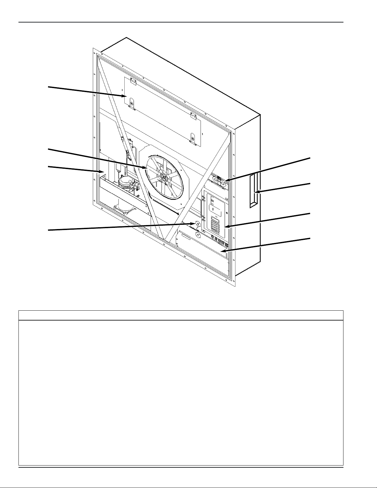
Typical Unit Front View
1. CSR40 PS: Evaporator Access Door, 1018 mm (40.08 in.) Wide with Two Latches
2. Condenser Fan
3. Compressor Compartment
4. Return Air Sensor Probe Holder
5. Power Cord Storage Compartment
6. Control Box
7. Rear Download and USDA Receptacle Panel (Access from Inside Container)
8. Fresh Air Exchange Vent
6
5
CSR40-149 & -150 PS Hermetic, June 2000
Page 29
Unit Description Unit Illustrations 2-5
1
2
4
Unit Options Front View
1. Recording Thermometer Option
2. Dual Voltage Option
3. Advanced Fresh Air Management (AFAM) Option
4. Humidify System Option
3
CSR40-149 & -150 PS Hermetic, June 2000
Page 30
2-6 Unit Illustrations Unit Description
12 3 4 5
CSR40 PS Evaporator Section — Front View
1. Evaporator Fan Motor
2. Evaporator Fan Blade:
• CSR40 PS: 355 mm (14.0 in.) diameter, 25opitch
3. Supply Air Sensing Bulb for Recording Thermometer (Option)
4. Supply Air Sensor
5. Humidify System Compressor (Option), see page 2-10
CSR40-149 & -150 PS Hermetic, June 2000
Page 31

Unit Description Unit Illustrations 2-7
1
18
17
2
16
3
4
15
5
14
6
7
13
8
12
9
11
Hermetic Refrigeration System
1. Evaporator Coil 17. Warm Gas Bypass Solenoid Valve
2. Tube (Standard) 18. Dehumidify Valve (Option replaces standard tube)
3. Expansion Valve
4. Heat Exchanger
5. One-piece Filter Drier/In-line Filter
6. Stepper Motor Valve
7. Compressor Discharge Temperature Sensor
8. Liquid Injection Solenoid Valve
9. Scroll Compressor
10. Suction Line Process Tube
11. Low Pressure Cutout Switch
12. Discharge Line Process Tube
13. High Pressure Cutout Switch
14. Condenser Coil
15. High Pressure Relief Valve
16. Receiver Tank
CSR40-149 & -150 PS Hermetic, June 2000
10
Page 32

2-8 Unit Illustrations Unit Description
11
1
2
3
4
5
MP-3000 Controller
1. Battery Cable Connection to Controller
2. Cable No. 2 Connection to Controller
3. Download Cable Connection to Controller
4. Cable No. 3 Connection to Controller
5. Cable No. 1 Connection to Controller
6. Control Box Cover and Controller Keyboard Decal
7. Special Function Keypad
8. General Purpose Keypad
9. LCD Display (Setpoint Temperature, Message and Controller Main Menu Tree Display)
10. LED Display (Return or Supply Air Temperature Display and Status Indicator LEDs)
11. MP-3000 Controller
10
9
8
7
6
CSR40-149 & -150 PS Hermetic, June 2000
Page 33

Unit Description Unit Illustrations 2-9
8
7
6
1
2
3
Unit Control Box
1. Unit On/Off Switch
2. Communications Connector for Data Retrieval
3. Circuit Breaker
4. Main Relay Board
5. 12 Vdc Battery
6. Control Power Transformer
7. Compressor Contactors (2)
8. 25 Ampere Main Power Circuit Breaker
5
4
CSR40-149 & -150 PS Hermetic, June 2000
Page 34

2-10 Unit Illustrations Unit Description
10
9
8
1
2
3
4
5
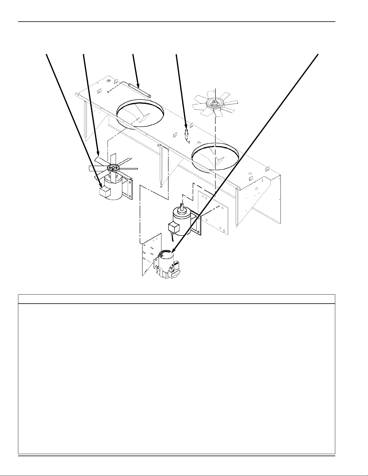
Humidify System Option
1. Evaporator Drain Hose
2. Fill Cap
3. Water Tank Heater
4. Tank Overflow Hose
5. Drain Cock
6. Water Tank
7. Water Filter
8. Water Supply Hose
9. Air Compressor
10. Liquid Spray Nozzle
7
6
CSR40-149 & -150 PS Hermetic, June 2000
Page 35

Unit Description Unit Illustrations 2-11
1
2
8
3
4
5
Advanced Fresh Air Management (AFAM) Option
1. Gasket
2. Vent Door Assembly
3. Linkage Assembly
4. Damper Motor Housing
5. Damper Motor Assembly Mounting Bracket
6. Stop Bracket, Vent Door Full Open
7. Stop Bracket, Vent Door Closed
8. Grille
7
6
CSR40-149 & -150 PS Hermetic, June 2000
Page 36

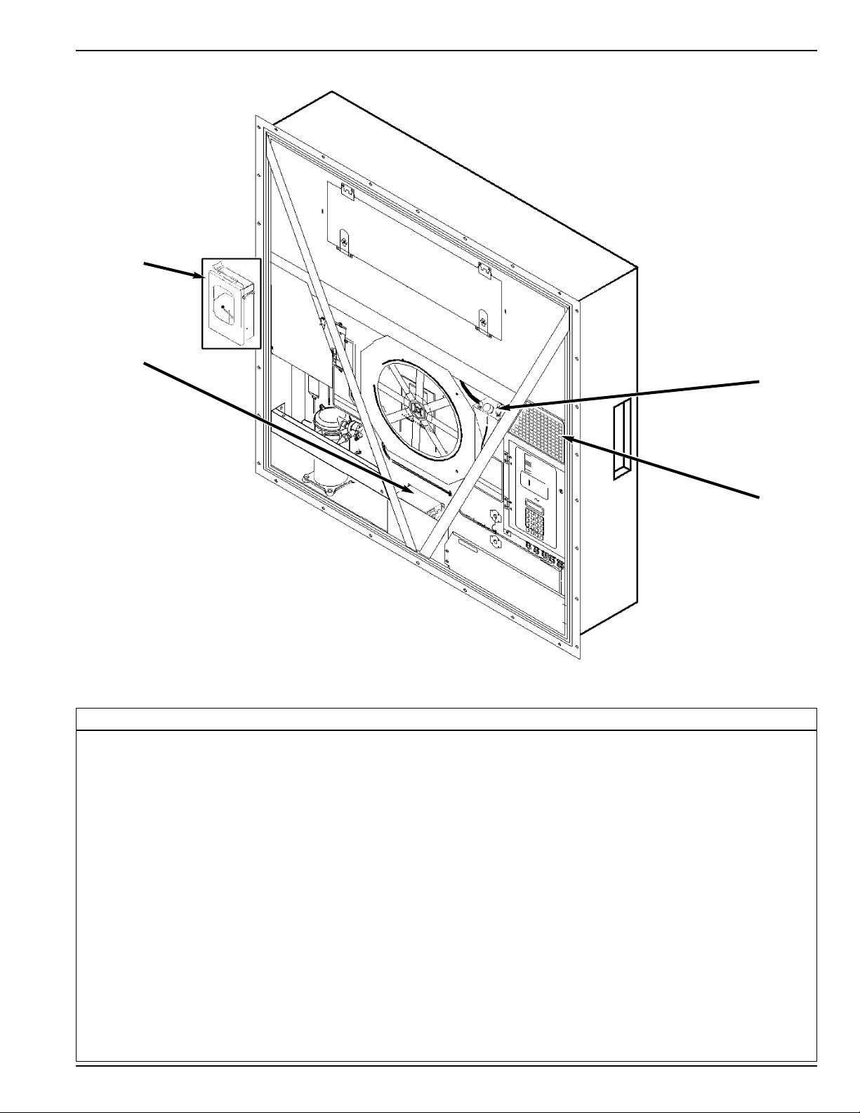
2-12 Unit Illustrations Unit Description
1
2
3
4
5
6
Typical Unit Back View
1. Evaporator Grille
2. Unit Gasket
3. Humidity Sensor (Option)
4. Top Rear Plate
5. Bottom Rear Plate
6. Sensor Connector Assembly:
• Controller Communications and Data Download Port
• USDA1/Spare 1 Sensor Connection
• USDA2/Spare 2 Sensor Connection
• USDA3/Spare 3 Sensor Connection
• Cargo (Pulp) Sensor Connection
CSR40-149 & -150 PS Hermetic, June 2000
Page 37

3 Operating Instructions
The In-range LED illuminates when the controlling
Unit Controls
Unit Control Box
1. UNIT ON/OFF SWITCH.
a. ON position. Unit will operate on cool or heat
depending on the controller setpoint temperature and
the container air temperature.
b. OFF position. The unit will not operate.
MP-3000 Controller
The MP-3000 microprocessor controls all unit functions to
maintain the cargo at the proper temperature. The controller
also monitors and records system faults and performs pre-trip.
1. KEYPAD. Sixteen general purpose keys are used to display information, change the setpoint, change programmable features and initiate control tasks.
2.oC–oF KEY. Press this key to view temperatures in the
LED display in the alternate temperature value. Alternate
value (C or F) shows while the key is pressed.
3. RET/SUP KEY. Press this key to view the alternate sensor temperature in the LED display. Alternate sensor
(return or supply) shows while the key is pressed.
4. DEFROST KEY. Press this key to initiate a manual
defrost cycle. If the evaporator coil temperature is below
18 C (65 F), the unit will defrost. Otherwise the controller
will display “Defrost Not Activated” in the LCD display
and the unit will continue normal operation.
5. SETPOINT KEY. Press this key to change the setpoint.
Cursor in the LCD display automatically appears in the
“TEMP SETP” line of the Data menu. See “Changing the
Setpoint” in the MP-3000 Controller chapter for complete
instructions.
6. STATUS INDICATOR LEDs located in the large LED
display signal:
• Supply (Air Temperature)
• Return (Air Temperature)
• Humidity Mode (Humidification Option set to On in
Setpoint menu)
• Compressor (Cooling On)
• Heat (On)
• Defrost
• In-Range (Temperature)
• Alarm
air sensor temperature is less than 1.5 C (2.7 F) above setpoint (standard). The controller maintains the in-range
signal during defrost and after defrost for 60 minutes.
7. LED DISPLAY. Large red LED display shows current
control temperature during normal operation. LED display also shows current test state during a Pretrip (PTI) or
Function test.
8. LCD DISPLAY. A 4-line LCD message display shows
setpoint during normal operation. LCD display also
shows controller menu and unit operation information
when special keys are pressed.
Other Unit Controls
1. EVAPORATOR OVERHEAT SWITCH. A temperature
switch near the evaporator coil opens to de-energize the
heater contactor if the evaporator temperature reaches 54
+/- 3 C (130 +/- 5 F). The switch closes (resets) when the
evaporator temperature decreases to 38 +/- 4.5 C (100 +/8 F).
Unit Instruments
1. RECORDING THERMOMETER (OPTION). The
recording thermometer indicates and permanently records
the temperature of the supply air leaving the evaporator
section on a calibrated chart.
Unit Protection Devices
1. MAIN CIRCUIT BREAKER. A 25 ampere manual reset
circuit breaker protects the 460/380V power supply circuit
to the unit electric motors and control system transformer.
The main power circuit breaker is located in the control
box.
2. CONTROL SYSTEM CIRCUIT BREAKER. A 7 ampere
manual reset circuit breaker protects the 29 Vac control
circuit. This circuit breaker is located in the control box
beside the On/Off switch.
CSR40-149 & -150 PS Hermetic, June 2000
Page 38

3-2 Unit Protection Devices Operating Instructions
3. FUSES. A number of fuses are located on the main relay
board and controller plug to protect unit circuits and components.
• Three 20 amp fuses protect high voltage circuits on the
main relay board.
• A 2 amp fuse protects the controller’s 28 V system.
• A 2 amp fuse protects the controller’s battery charging
circuit.
4. COMPRESSOR DISCHARGE GAS TEMPERATURE
SENSOR. A refrigerant injection system uses the compressor discharge temperature to determine when cold
refrigerant will be injected into the center scroll of the
compressor to protect the compressor from excessively
high operating temperatures.
a. Chill Mode Liquid Injection:
• Controller energizes the liquid injection valve when
compressor discharge gas temperature increases to
138 C (280 F).
• Controller de-energizes the liquid injection valve to
stop liquid injection when the discharge gas temperature decreases to 132 C (270 F).
b. High Temperature Protection:
• The controller immediately stops unit operation if
the discharge gas temperature increases to 148 C
(298 F). The controller activates the Alarm LED
and records Alarm 56, Compressor Temperature
Too High. The controller restarts the unit when the
condition corrects itself.
5. HIGH PRESSURE CUTOUT (HPCO) SWITCH. If the
compressor discharge pressure rises above 3243 +/- 7 kPa,
32.43 +/- 0.48 bar, 470 +/- 7 psig, the high pressure cutout
opens to interrupt the ground circuit to the compressor
contactor:
• Compressor STOPS immediately.
• Evaporator and condenser fans continue normal opera-
tion. Controller determines that a high pressure cutout
switch is open when the unit current draw decreases by 7
amps for more than 3 seconds.
• The controller LCD display shows a High Pressure
Cutout message: “High Pressure Cutout Check
Condenser Probe” or “High Pressure Cutout Check
Condenser Fan”.
• After 1 minute, the controller energizes the compressor
contactor so the compressor will restart when the overload condition is corrected (switch resets) if power is
available. The high pressure switch resets (closes) when
the pressure drops to 1590 +/- 70 kPa, 15.9 +/- 0.7 bar,
230 +/- 10 psig.
• If the switch remains open for 5 minutes, controller also
activates Alarm LED and records Alarm 37, Total Power
Consumption Too Low.
6. LOW PRESSURE CUTOUT (LPCO) SWITCH. If the
compressor discharge pressure decreases to +21 to -21
kPa, +0.21 to -0.21 bar, 3 psig to 6 in. Hg vacuum; the
low pressure cutout opens:
• Compressor STOPS immediately.
• Evaporator and condenser fans continue normal opera-
tion.
• Compressor will restart if the low refrigerant condition is
corrected (switch closes) as long as power is available.
The low pressure switch resets (closes) when the pressure increases to 48 to 90 kPa, 0.48 to 0.90 bar, 7 to 13
psig.
NOTE: If the low pressure cutout switch remains
open, check for an obstruction or refrigerant leak
in the low or high pressure side of the refrigeration system.
7. HIGH PRESSURE RELIEF VALVE. A high pressure
relief valve is installed in the liquid line between the
receiver tank and filter drier. The relief valve protects
against excessive pressure build-up within the refrigeration system from extraordinary and unforeseen circumstances. The valve is a spring-loaded piston that lifts
when refrigerant pressure exceeds 3447 +520/-104 kPa,
34.47 +5.20/-1.04 bar, 500 +75/-15 psig. The valve is
located so that refrigerant pressure expelled from the
valve would be directed away from anyone servicing the
unit. The valve will reset when this pressure drops to 2758
kPa, 27.58 bar, 400 psig. The valve is non-repairable and
requires no adjustment. If the valve fails to reseat properly, recover the refrigerant charge and replace the valve.
8. OVERLOAD PROTECTION. The condenser fan motor,
evaporator fan motors and compressor motors include
internal overload protection with automatic reset.
9. PHASE SEQUENCE SELECTION. When the On/Off
switch is turned ON, phase sensors on the main relay
board determine the incoming power phase to ensure the
correct sure proper condenser fan and evaporator fan rotation. The controller then determines the correct phase
sequence for the compressor and energizes the correct
compressor contactor.
CSR40-149 & -150 PS Hermetic, June 2000
Page 39

Operating Instructions Pretrip Inspection 3-3
• If the controller calls for cooling, the compressor motor
Pretrip Inspection
Visual Inspection
The following inspections should be made before the container
is loaded:
1. Visually check the unit for physical damage.
2. Check the electrical connections in the unit control box,
making sure they are fastened securely.
3. Check the conditions of wires and terminals. Repair or
replace if necessary.
4. Check the refrigeration system for leaks. Inspect for evidence of oil leaks at all joints and connections.
5. Check the condenser and evaporator coils. Clean if necessary. Use an air or water spray jet directed against the coil
from the air discharge side. Also inspect the condenser
fan grille for damage. If the grille is damaged or missing,
abnormally high head pressure may result. Repair or
replace the grille if necessary.
CAUTION: Air or water spray jet pressure should
not be high enough to damage (bend) coil fins.
6. Check the mounting bolts on the unit, compressor and fan
motors. Tighten if necessary.
7. Clean the defrost drains.
8. Optional: Check water level in humidity system tank.
Add only demineralized or distilled water to prevent plugging of the atomizing nozzle.
9. Observe the unit for proper operation and functions during
Pre-load Operation.
10. Check to be sure the container ID that appears in the
Configuration menu is correct.
Functional Inspection
To properly perform a Full Pretrip Test on units equipped with
a MP-3000 controller, the container must be empty with the
rear doors closed.
1. Start the unit (see “Starting the Unit and Adjusting the
Controller Setpoint” on page 3-4). A second sequence
start of the required loads occurs during the Pretrip test:
• Controller LED display turns On and then Off.
• LED display briefly shows setpoint and then displays the
controlling (return) air sensor temperature.
• Controller senses the incoming power phase and selects
the correct power phase to unit components.
• Controller energizes unit loads, starting the evaporator
fans. The condenser fan may also start (if required).
starts. If the unit starts in Modulation Cool the stepper
motor valve opens or closes to the required setting.
• If the controller calls for heating, the electric heaters are
energized.
NOTE: If the compressor fails to start, turn the
On/Off switch OFF. Then repeat steps 1 through
3. If the unit still does not start, refer to “Alarm
Codes, Descriptions and Corrective Actions” in
the MP-3000 Controller chapter of this manual.
2. Check controller setpoint for proper setting. Adjust if
necessary.
NOTE: New setpoint must be between -29 C and
+29 C (-20.2 F and +84.2 F) or controller will
return to the previous setpoint display.
3. Check the direction of the condenser airflow (see
“Condenser Fan and Evaporator Fan Rotation” in the
Electrical Maintenance chapter of this manual).
4. Check direction of evaporator airflow (see “Condenser
Fan and Evaporator Fan Rotation” in Electrical
Maintenance chapter of this manual).
5. Perform a Pretrip (PTI) Test to check the unit refrigeration
and electrical systems for proper operation.
CAUTION: The PTI test should only be performed on an empty container!
NOTE: Correct all existing alarm conditions and
clear the alarm codes before performing a PTI
test. The controller will automatically clear all
existing alarms before beginning the PTI test.
To perform a PTI test:
• Press F2 key to enter Main Menu.
• Press F2 or F3 key to scroll up or down in menu to
“COMMANDS”.
• Press F4 key to access COMMANDS menu.
• Press F2 or F3 key to scroll up or down to “PTI”.
• Press F4 to start the PTI (Pretrip) Test.
• The controller then performs the Pretrip Test.
• Observe the unit for proper operation and functions dur-
ing pretrip test.
• LCD display shows PTI Test currently being performed.
PTI test ends automatically. Press any key on the controller to return the unit to normal operation.
CSR40-149 & -150 PS Hermetic, June 2000
Page 40

3-4 Starting the Unit Operating Instructions
• If an operating problem occurs during the Pretrip Test,
the Alarm LED will turn ON and FLASH. An “E” may
also appear in the right side of the LED display. View
and correct any alarm conditions. Then clear (acknowledge) the Alarm Code(s) and repeat the PTI Test.
NOTE: Clear the Alarm codes ONLY after the
alarm codes are documented and problems
repaired. A permanent record of the alarm codes
remains stored in the datalogger memory for
retrieval via DRU-II or SmartSponge retriever
Starting the Unit and Adjusting the
Controller Setpoint
CAUTION: Supply power connections from the unit
to the power source must always be made with the
refrigeration Unit On/Off switch and power supply
On/Off switch in the OFF positions. Never attempt to
start or stop the refrigeration unit with the unit power
cable.
software.
1. Verify that the Unit On/Off switch is in OFF position.
6. Enter trip ID information into the controller using the keypad.
7. Optional: Adjust the fresh air exchange rate to the desired
setting.
NOTE: The use of the Advanced Fresh Air
Management option should be established by the
shipper.
• AFAM System (Option): Set the AFAM Control screen
in the Setpoint Menu to ON. Then set the AFAM Delay
and AFAM Rate (see “Changing the Advanced Fresh
Air Management [AFAM] Mode Setting” on page 4-14).
2. Connect the unit power cord to proper power source:
• 460/380V power cord to 460/380V, 60-50 Hz power
source.
• Turn the power supply On/Off switch ON.
3. Switch the Unit On/Off switch to ON position. Check for
condenser fan and evaporator fan motor operation (see
“Condenser Fan and Evaporator Fan Rotation” in the
Electrical Maintenance chapter of this manual). If the unit
was properly pretripped, correct condenser fan rotation
will also indicate correct evaporator fan rotation.
4. Adjust controller setpoint to the desired temperature:
NOTE: The setpoint temperature can be set
between -29 C and +29 C (-20.2 F and +84.2 F) in
NOTE: If Dehumidification is turned ON, the
fresh air vent will close.
either oF or oC using the oC/oF key. Just press
and hold the F/C key (to display the alternate
temperature scale).
8. Optional: Operate the humidify system (see “Changing
the Humidity Mode Setting” on page 4-14).
NOTE: The use of the Humidify option should be
established by the shipper.
a. Verify that the air compressor operates and that water
is drawn into the atomizing nozzle and injected into
the return air stream (see “Humidify System” on page
7-2).
b. Adjust the humidity setpoint (see “Changing the
Humidity Setpoint” on page 4-14).
9. Install a new chart and prepare the recording thermometer
for temperature recording (if so equipped):
• Wind the chart drive on the recording thermometer
(Partlow recorders).
10. Stop the unit by moving the On/Off switch to the OFF
position.
• Press SETPOINT key to display cursor flashing in the
“TEMP SETP” line.
• Press F4 key to activate the setpoint change function.
An Enter Arrow appears in the menu line and the current
setpoint disappears.
• Enter minus sign (if required) first by pressing EXIT
key. Then press numeric keys to enter new setpoint.
• With correct setpoint in display, press and hold F4 key
until cursor stops flashing. Controller places new setpoint in controller memory and shows new setpoint in
LCD display.
NOTE: New setpoint must be between -29 C and
+29 C (-20.2 F and +84.2 F) or controller will
return to the previous setpoint display.
NOTE: If the setpoint is not entered within 30
seconds, the controller will default (return) to the
previous setpoint. If this occurs, repeat step 3.
CSR40-149 & -150 PS Hermetic, June 2000
Page 41

Operating Instructions Loading Procedure 3-5
Loading Procedure
1. Make sure the Unit On/Off switch is OFF before opening
the container doors. (The unit may be operating when
loading the container from a warehouse with door seals.)
2. Spot check and record load temperature while loading.
Especially note any off-temperature product.
Post Load Procedure
1. Make sure all doors are closed and locked.
2. Start unit if unit is OFF.
3. Check controller setpoint for proper setting.
4. Enter trip identification information into the controller
memory by selecting “Cargo Data” from the MISC
FUNCTIONS menu of the controller.
5. One-half hour after loading, initiate a manual defrost
cycle:
• Press the DEFROST key. The Defrost and Heat LEDs
turns ON as the unit enters Defrost. Defrost will stop
automatically.
NOTE: The evaporator coil temperature must be
below 18 C (65 F) to allow the unit the enter a
defrost cycle. If the evaporator coil temperature
is too high, the LCD display will read “Defrost
Not Activated”.
Post Trip Procedure
Trip data recorded by the MP-3000 datalogger may be down
loaded via the communications port on the control box using a
DRU-II hand-held data retriever, or laptop computer with
SmartSponge retriever software; or via the REFCON remote
monitor system.
CSR40-149 & -150 PS Hermetic, June 2000
Page 42

Page 43

4 MP-3000 Controller
Controller Description
The MP-3000 is an advanced microprocessor controller that
has been specially developed for control and monitoring of
refrigeration units. The controller contains the following basic
features:
1. LED display for TEMPERATURE:
• Five alpha numeric, 20.32 mm high characters:
Numerical hundreds, tens, ones and tenths position, a C
for Celsius or F for Fahrenheit for temperature display.
• LED display shows controlling (return or supply) sensor
temperature. Sensor temperature shown in LED display
is indicated by status indicator lights. If a sensor is out
of range the display shows “+Err” or “-Err”. The +/sign indicates whether the sensor temperature is out of
range high or low.
• The LED display also shows the test stage of a Pretrip
(PTI) or Function test.
2. LCD display for SETPOINT, MESSAGES and MENU:
• 4 line, 80 character LCD display shows setpoint temper-
ature during normal operation.
• Alarms, messages and the controller menu also appear in
the LCD display when special keys are pressed.
3. Sixteen general purpose keys are used to enter text and
scroll through the controller menu tree.
a. Text Input: The keyboard supports both numerical
and text input. Each key can have more than one meaning. Use the special text keys F1, F2, F3 and F4 to enter
text in an information screen:
• F1 key: Press the F1 key, then press another general
purpose key to enter the number shown on the key.
• F2 key: Press the F2 key, then press another general
purpose key to enter the first letter shown on the key.
• F3 key: Press the F3 key, then press another general
purpose key to enter the second letter shown on the key.
• F4 key: Press the F4 key, then press another general
purpose key to enter the third letter shown on the key.
MP3000 Controller
NOTE: When the F1, F2, F3 or F4 key is pressed
to enter a character in the display, the keypad
remains on that “character level” until another
“level” is selected by pressing the F1, F2, F3 or
F4 key.
1. LED display for TEMPERATURE. Status indicator
LEDs identify controlling sensor temperature (return
or supply) that appears in display.
2. LCD display for SETPOINT, MESSAGES and
MENU. Use the keypad to scroll through messages
and the controller menu.
3. General purpose keys are used to enter text and
scroll through menus.
4. Special function keys perform specific tasks.
CSR40-149 & -150 PS Hermetic, June 2000
Page 44

4-2 Controller Description MP-3000 Controller
Text Input Example: To enter THERMO in an information screen:
a. Enter “T” by pressing F3 key, then pressing STU key.
b. Enter “H” by pressing GHI key.
c. Enter “E” by pressing DEF key.
d. Enter “R” by pressing F4 key, then pressing PQR
key.
e. Enter “M” by pressing F2 key, then pressing MNO
key.
f. Enter “O” by pressing F4 key, then pressing MNO
key.
b. Menu Scrolling: General text keys F1, F2, F3 and
F4 also include directional arrows for entering and
scrolling through the controller Main Menu:
• F1 key: ESC indicates that pressing the F1 key moves
the cursor out of (exits) a menu list.
• F2 key: FORWARD/UP ARROWS indicate that pressing the F2 key scrolls the cursor forward and/or upward
through text boxes and menu lists.
• F3 key: BACKWARD/DOWN ARROWS indicate that
pressing the F3 key scrolls the cursor backward and/or
downward through text boxes and menu lists.
• F4 key: ENTER ARROW indicates that pressing the F4
key moves the cursor into the next menu level or into a
menu item text box.
4. Four special function keys (see illustration on page 4-1):
• C/F key: Press to view alternate temperature scale in
LED display.
• DEFROST key: Press to initiate defrost. Evaporator
coil temperature must be below 18 C (65 F).
• SUP/RET key: Press to view alternate return/supply
sensor temperature in LED display.
• SETPOINT key: Press to enter Setpoint Menu. The
first line of the Setpoint Menu is the setpoint temperature. Press F2 or F3 key to scroll up or down through
the menu list.
NOTE: Press the “5” key to increase the display
time of the current LCD data screen by 5 minutes. Maximum display time is 30 minutes for
data screens and 100 minutes for manual tests.
5. Status indicator LEDs (see “Status Indicator LEDs and
Alarm Codes” in this chapter).
6. Control Transformer: Low voltage control power and
ground is supplied to the MP-3000 controller and the main
relay board.
7. Main Relay Board: High voltage supply power and low
voltage control power and ground are supplied to the main
relay board. The main relay board contains:
• Relays to energize and de-energize unit contactors and
solenoids. Component relays include the heater, evaporator fan motor, condenser fan motor, and phase reversal
relays.
• Supply power circuit protection:
- 20 amp fuses (3) protect the high voltage circuits on the
main relay board.
• Control circuit fuse and circuit breaker protection:
- 7 amp manual reset circuit breaker protects the 24 Vdc
control circuit.
- 2 amp fuse protects the 28V ac control power circuit to
the controller.
- 2 amp fuse protects the battery charger output circuit to
the controller.
• Electronics for measuring phase sequence.
• Electronics for measuring amperage.
• Electronics for measuring voltage.
• Zero current transformer for earth leaking measurement
(option).
8. Replaceable sensors: Return air, supply air, evaporator
coil (defrost), condenser coil, ambient air and compressor
discharge (top cap) temperature sensors are field replaceable. Three (replaceable) spare sensor receptacles are also
provided for USDA temperature recording.
9. Probe Test (see “Probe Test” in this chapter).
10. Defrost cycle control (see “Defrost System” in this chapter).
11. Pretrip (PTI) test capability (see “PTI (Pretrip) Test” in
this chapter).
12. Function test capability (see “Function Test” in this chapter).
13. Data recording capability (see “Data Recording and
Downloading Data” in this chapter).
14. Electronic phase selection: The microprocessor relay
board monitors the phase of the power supply to ensure
proper rotation of the condenser fan and evaporator fans.
The controller determines the correct phase sequence for
the compressor and energizes the correct compressor contactor.
15. Power limit control (see “Power Limit Mode” in this
chapter)
16. Sequential component start-up control: A sequence start
of the required loads occurs during initial start-up of the
controller and when a control mode shift requires the
compressors to start (see “Sequence of Operation” in this
chapter).
17. Compressor refrigerant injection cycle control (see
“Compressor Liquid Injection” in this chapter).
18. Hourmeters: The MP-3000 controller has multiple built-in
hourmeters that can be accessed through the Main Menu.
19. Manual emergency control capability. Manual control
settings in the control box allow the unit to operate even
CSR40-149 & -150 PS Hermetic, June 2000
Page 45

MP-3000 Controller Status Indicator LEDs 4-3
in the event of a fatal failure of the controller. Manual
control offers three operating functions: Heat, Defrost
and Cool (see “Manual Emergency Mode Operation” in
this chapter).
20. Flash memory: Flash program memory allows the application software to be updated without replacing a EPROM
chip on the controller. Application software can be updated in the field using a portable computer and the MP-3000
Loader program. Consequently, the field installed application software version may have a different revision
number and may include control features not included in
the original factory installed software. If the operation of
your unit differs from the Sequence of Operation
described for the unit in this manual, enter “Misc.
Functions” in the Main Menu to check that the program
version is correct (see “Menu Operating Instructions” in
this chapter).
21. Display menus: The MP-3000 controller contains an
extensive display menu that can be navigated via keypad.
The display menu is organized into eight (8) Main Menus:
NOTE: The screens that display on the controller
Status Indicator LEDs
Eight status indicator LEDs are located in the top LED display
and signal the following:
• Supply (Air Temperature)
• Return (Air Temperature)
• Humidity Mode (Humidification set to On in Setpoint
menu)
• Compressor (Cooling On)
• Heat (On)
• Defrost
• In-Range (Temperature)
• Alarm
The indicator LEDs stay ON continuously to indicate sen-
sor temperature display, unit operating mode or condition.
The Alarm LED flashes ON and OFF continuously when
a Check Alarm (Level 2 Alarm) or Shutdown Alarm (Level
1Alarm) occurs. Less serious Log Alarms (Level 3 Alarm) are
recorded but do not activate the Alarm LED (see Alarms Menu
on page 4-16 for more information).
are determined by the controller software setting
and the options installed on the unit. All screens
are NOT present on all units.
• Setpoint Menu: Menu screens in this group are used to
enter the temperature setpoint and set the economy
mode. Setpoint menu option functions include: set
humidify or dehumidify operation, enter humidity setpoint, set airflow, set custom airflow, set bulb mode, set
AFAM operation, set AFAM delay, set AFAM rate, set
O2Minimum and set CO2Maximum.
• Data Menu: Menu screens in this group are used to display unit operating information including sensor temperatures, voltage, current and frequency information.
• Alarm List Menu: Menu screens in this group display a
list of alarm code(s).
• Commands Menu: Menu screens in this group are used
to activate defrost, function tests, pretrip (PTI) tests and
manual function test.
• Miscellaneous Functions Menu: Menu screens in this
group display date/time, C/F, cargo data, program version and run time (hourmeters) information.
• Configuration Menu: Menu screens in this group display
refrigerant type, in-range setting, container ID, contrast
(screen), language, unit type, reefer type and zero current status.
• Datalogger Menu: Menu screens in this group display
temperature log, event log, set log time and PTI log.
• Refcon Remote Monitoring (RMM) State: Menu screen
show current remote monitoring state (Offline, Zombie
or On-line).
Data Recording and Downloading Data
The MP-3000 datalogger can record sensor temperatures as
well as loss of power, alarms, sensor failure, setpoint change
and unit shutdown events. All data logs include the time and
date; setpoint temperature; supply, return, ambient, USDA1,
USDA2 and USDA3 sensor temperatures; and humidity sensor. All temperature logs can be viewed from the controller’s
LCD message display.
Data logging intervals are selectable from 1 minute or 1/2,
1, 2 or 4 hours. When a 1 hour logging interval is selected, the
datalogger memory can store approximately 680 days of information.
The logging of USDA sensors is fixed at 1 hour intervals
to comply with USDA requirements. A logging test of USDA
sensors at 1 minute intervals is possible for 72 minutes.
USDA data can be downloaded during the logging test. After
72 minutes, controller returns to previous logging interval and
clears USDA test data from datalogger memory.
If the unit power supply is disconnected, the datalogger
will continue to register 120 temperature logs (except humidity
sensor) when battery voltage is above 11.4 volts. These will
be maintained until the unit is re-connected to power, and the
battery automatically re-charged.
Trip data can be retrieved (but not erased) from the datalogger memory using a DRU-II or SmartSponge handheld data
retriever, or a REFCON power line remote monitoring system.
DRU-II data transfer rate based on a 1 hour log interval is
about 15 seconds per month of event logs and about 70 seconds per month of temperature logs. For example, download-
CSR40-149 & -150 PS Hermetic, June 2000
Page 46

4-4 General Theory of Operation MP-3000 Controller
ing 90 days of data logs would take about 95 seconds for event
logs only and about 210 seconds for temperature logs only.
Trip data from separate units is denoted by the identification information entered into the controller at the beginning of
the trip via the general purpose keypad. Identification data
may include the container ID number, location B.R.T., contents, loading data, voyage no., ship, load port, discharge port
and comments. The container ID number is stored in the
Configuration submenu.
General Theory Of Operation
The MP-3000 controller uses advanced solid-state integrated
circuits to monitor and control unit functions. The controller
monitors inputs from:
• Return air sensor
• Supply air sensor
• Evaporator coil sensor
• Condenser coil sensor
• Ambient sensor
• Humidity sensor
• USDA (Spare) sensors 1, 2 and 3
• Compressor discharge (top cap) temperature sensor
• Phase measuring circuits
• Current measuring circuits
• Voltage measuring circuits
Output signals from the controller automatically regulate all
unit functions including:
• Compressor operation
• Condenser fan operation
• Evaporator fan motor operation
• Stepper motor valve
• Liquid injection valve
• Dehumidify valve
• Electric heaters
• Phase selection
Chill Loads (Setpoint at -9.9 C [14.1 F] and
Above)
The unit operates on Cool with Modulation and Heat to
provide accurate control of chill loads. During Cool with
Modulation, the controller uses a proportional-integral derivative (PID) algorithm and a stepper motor valve to provide
accurate control of the container temperature in direct response
to load demand.
The stepper motor valve is installed in the suction line and
controls the amount of refrigerant returning to the compressor.
The valve opens and closes in response to a controller voltage
signal based on a control temperature differential. The controller uses the setpoint temperature, supply air sensor temperature and pull-down rate for the last 10 seconds, last 20 seconds and last 180 seconds to calculate the control temperature
differential.
If the supply air sensor fails, the controller uses the temperature of the return air sensor plus an offset for temperature
control.
Temperature Control Accuracy and Frost Protection
The PID algorithm generally minimizes container temperature
fluctuations to +/- 0.1 C (+/- 0.2 F). Additional frost protections is provided by pulsing the electric heaters ON and OFF
on a 60 second duty cycle to increase the supply air temperature if the return air temperature decreases to within 0.3 C (0.5
F) of setpoint. The controller pulses the heater ON for 2 to 60
seconds every 60 seconds. The amount of ON time depends
on the amount of heat required to provide frost protection.
CSR40-149 & -150 PS Hermetic, June 2000
Page 47

MP-3000 Controller General Theory of Operation 4-5
Frozen Loads (Setpoint at -10 C [14 F] and
Below)
The unit operates on Full Cool and Null to provide accurate control of frozen cargo. The controller uses the return air
sensor temperature and setpoint temperature to regulate unit
operation.
If the return air sensor becomes disconnected or fails, the
controller uses the supply air sensors plus an offset for temperature control.
Modulation Display in Data Menu
The modulation percent displayed in the Data menu indicates
the percent of the total unit capacity that is currently provided.
For example, when controller display shows 70%, this means
the stepper motor valve has closed to reduce system cooling
capacity from 100% to 70% (a 30% reduction).
Power Limit Mode
The controller uses the total unit current and the condenser
temperature to provide power limit control in both the Chill
and Frozen modes. When the unit is on water-cooled operation, power limit control is based on the total unit current draw
only.
Initial Unit Start-up and Normal Operation (Standard)
Power Limit is active whenever the compressor is ON in both
the Chill and Frozen modes. When the total current draw or
the condenser temperature exceeds a predetermined threshold,
the controller limits unit power consumption by sending a
voltage pulse to the stepper motor valve. The stepper motor
valve then closes to restrict the flow of refrigerant to the compressor. This reduces the cooling capacity load on the compressor, thereby limiting the compressor motor current draw
and the condenser temperature to a predetermined threshold.
Power Limit Management
Additional power limit management flexibility is available. A
maximum total current draw (17, 15 or 13 amps) and power
management time interval can be selected from the Power
Management feature of the Commands menu. When the
power management time interval expires, the unit returns to
the standard power limit control algorithm.
Compressor Liquid Injection
During compressor operation, a liquid injection system injects
refrigerant into the center scroll of the compressor to protect
against excessively high operating temperatures. When liquid
injection is active, the controller energizes the liquid injection
valve continuously. The controller activates liquid injection
when the:
• Compressor starts. The controller turns on liquid injection
for 5 minutes after each compressor start-up. Compressor
start-ups include initial unit start, start after Defrost and start
after Null.
• Chill or Power Limit Mode: When the modulation percent is
75% or less (in the Data menu display), the controller energizes liquid injection valve continuously.
• Compressor discharge temperature exceeds 138 C (280 F).
Liquid injection stops when the compressor discharge temperature decreases to 132 C (270 F).
Warm Gas Bypass
During Chill Mode operation, a warm gas bypass system
diverts refrigerant from the high side to the suction line as the
supply air temperature decreases toward setpoint. This
reduces unit cooling capacity and increases refrigerant flow
through the compressor. The controller activates the warm gas
bypass valve when:
• Chill Mode: When the modulation percent is 25% or less (in
the Data menu display), the controller energizes warm gas
bypass valve on a 30 second duty cycle. The amount of On
(open) time increases as the modulation percentage decreases.
Evaporator Fan Control
The controller determines evaporator fan motor speed based
on the setpoint temperature and the Economy mode setting.
• Evaporator fans operate on HIGH speed at setpoints of -9.9 C
(14.1 F) and above. If the Economy mode is ON and temperature is In-range, the controller shifts the evaporator fans to
LOW speed.
• Evaporator fans operate on LOW speed at setpoints of -10 C
(14 F) and below. If the Economy mode is ON and the unit
is in the Null mode, the controller STOPS the evaporator
fans. The controller then operates the evaporator fans on
LOW speed for 5 minutes every 45 minutes as long as the
unit remains in the Null mode.
NOTE: Setting power management current at 13
amps can be used to provide slow pull-down of
loads.
CSR40-149 & -150 PS Hermetic, June 2000
Page 48

4-6 General Theory of Operation MP-3000 Controller
Condenser Fan Control
The controller also uses a proportional-integral derivative
algorithm to control the condenser temperature and ensure a
constant liquid pressure at the expansion valve. In low ambient conditions, the controller pulses the condenser fan ON and
OFF to maintain a minimum condenser temperature. The controller maintains a minimum 30 C (86 F) condenser temperature on Chill loads and a minimum 20 C (68 F) condenser temperature on Frozen loads.
Economy Mode Operation
The Economy Mode reduces unit power consumption by
reducing evaporator fan operation on both chill and frozen
loads. The use of the Economy Mode should be established by
the shipper and the type of cargo. The Economy Mode option
is turned on from Setpoint menu of the controller.
NOTE: Enter Setpoint temperature before turning
ON the Economy mode. The controller automatically
turns the Economy mode OFF when the setpoint is
changed.
Chill Loads (Setpoints of -9.9 C (14.1 F) and Above)
Evaporator fans operate on low speed whenever the container
temperature is In-range.
NOTE: On Chill loads, container air temperatures
may vary 1 C to 3 C (1.8 F to 5.4 F) above setpoint in
high ambient temperatures.
Frozen Loads (Setpoints of -10 C (14 F) and Below)
The evaporator fans stop during the Null mode. A null state
timer automatically re-starts the evaporator fans on low speed
for 5 minutes every 45 minutes.
The Economy Mode also modifies the temperature control
algorithm on frozen loads to extend the Null mode. The unit
continues on Cool operation until return air temperature reaches ECMIN temperature. Default ECMIN setting is 2.0 C (3.6
F) below setpoint. ECMIN temperature is adjustable from 0 to
5 C (0 to 8.9 F) below setpoint through the Configuration
menu of the controller.
The unit remains in Null until the return air temperature
increases to ECMAX temperature at the expiration of a 45
minute Null state time sequence. Default ECMAX setting is .2
C (0.4 F) above setpoint. ECMAX setting is adjustable from 0
to 5 C (0 to 8.9 F) above setpoint through the Configuration
menu of the controller.
NOTE: On Frozen loads, supply and return air temperatures may vary considerably during Economy
mode operation due to long periods of no air circulation.
Probe Test
The controller constantly monitors the supply sensor, return
sensor and defrost (evaporator coil) sensor to determine when
to initiate a demand defrost. If a demand defrost is requested
and defrost has occurred within last 90 minutes, the controller
initiates a Probe Test to check for a defective sensor.
During a Probe Test, the LCD display shows “ Probe Test
Please Wait”. The controller operates the unit on high speed
evaporator fans only for 5 minutes. All sensor temperatures
are then compared:
• Sensors with large temperature differences are discarded
from the control algorithm. The controller then activates the
appropriate Alarm codes to identify the defective sensor(s).
• If no sensors are found defective, controller LCD display
shows “Running with High Supply Difference” message.
Sensor errors recorded during a Probe Test are cleared
when the next Defrost is initiated or Unit On/Off switch is
turned OFF.
NOTE: A manual Probe Test can be performed by a
technician by selecting Sensor Check from the
Manual Test Function menu.
CSR40-149 & -150 PS Hermetic, June 2000
Page 49

MP-3000 Controller Sequence of Operation 4-7
Dehumidify Mode (Option)
During Chill mode operation, a dehumidification system is
available to reduce the relative humidity in the container to the
desired humidity setpoint. The Dehumidify Mode option is
turned on from Setpoint menu of the controller. The relative
humidity setpoint can be set from 50 to 99% from the Setpoint
menu too.
Changing the Humidify/Dehumidify Mode program
screen from OFF to ON activates the dehumidify control algorithm. The use of the Dehumidify Mode should be established
by the shipper. When the Dehumidify Mode is ON, the supply
air temperature must be in-range to activate dehumidification:
a. When the humidity level is 2% or more above setpoint,
the controller energizes (closes) the dehumidify valve.
This reduces the size of the evaporator providing cooling
by 50%, causing the coil to become colder and condense
more moisture from the container air.
b. When the humidity level is 5% or more above setpoint,
the controller also pulses the electric heaters ON and OFF.
This increases the cooling load on the evaporator coil,
thereby causing the coil to become even colder and con-
dense more moisture from the container air.
Sequence Of Operation
Unit Start-up
A 60 second sequence start of the required loads occurs during
initial start-up of the controller. If cooling (or heating) is
required, the unit operates in the cool (or heat) mode.
• When the unit On/Off switch is turned ON, the LED display turns On and then Off.
• The setpoint appears briefly in the LED display.
NOTE: When the setpoint appears in the LED
display, both the Return and Supply LEDs are lit.
• The LED then shows the controlling air sensor temperature.
• The controller senses the incoming power phase and
selects the correct power phase to unit components.
• About 40 seconds after the unit was turned ON, the evaporator fan motors start.
- Evaporator fans operate on high speed at setpoints of -
9.9 C (14.1 F) and above.
- Evaporator fans operate on low speed at setpoint temper-
atures of -10 C (14 F) and below.
• About 10 seconds later, the compressor starts if the controller calls for cooling.
• The condenser fan then starts if the condenser temperature
requires condenser fan operation.
• If the controller calls for heating, the electric heaters are
pulsed On and Off to provide heat.
• The controller turns ON the In-range LED when the controlling sensor temperature is within 1.5 C (2.7 F) of the
setpoint.
NOTE: Random time delays during the initial unit
start-up minimize peak current draw.
CSR40-149 & -150 PS Hermetic, June 2000
Page 50

4-8 Sequence of Operation MP-3000 Controller
Continuous Temperature Control Operation
Chill Loads — Controller Setpoint at -9.9 C (14.1 F) and
Above
The controller regulates the compressor, stepper motor valve
and electric heaters based on a Control Temperature
Differential (see “General Theory of Operation” in this chapter
for more detail). This means the unit operating mode can
NOT be predicted based ONLY on the setpoint and supply air
temperature.
At setpoints of -9.9 C (14.1 F) and above, the controller
operates the unit on:
• Cool mode with Modulation
• Controller energizes the liquid injection valve continuously when the modulation percent is 75% or less.
• Controller energizes the warm gas bypass valve on a 30
second duty cycle when the modulation percent is 25%
or less. The amount of ON (open) time increases as the
modulation percent decreases.
• Heat mode (electric heaters pulse On and Off on a 60
second duty cycle)
• Defrost mode (electric heaters On, evaporator fans Off)
• Evaporator fans operate on high speed (except when
Economy mode is ON and temperature is In-range) and
continuously circulate air inside the container (except
during defrost)
• Controller LED display shows the supply air sensor temperature.
• Controller LCD display shows the setpoint temperature.
• Controller uses the condenser coil temperature and a PID
algorithm to cycle a single-speed condenser fan between
ON and OFF on a 30 second duty cycle.
• Power limit is active when the unit is operating in the
Cool mode.
Heat
• Controller pulses electric heaters ON and OFF on a 60
second duty cycle for additional frost protection if the
return air temperature decreases to within 0.3 C (0.5 F)
of setpoint.
• Controller turns ON the Heat LED whenever the heaters
are pulsed ON and OFF.
• If the supply air temperature is too low and the Control
Temperature Differential is above the setpoint, the controller stops the compressor and pulses the electric
heaters ON and OFF on a 60 second duty cycle to provide heat. The controller pulses the electric heaters ON
and OFF until the supply air temperature increases to
setpoint.
Cool with Modulation
• Controller calls for the Cool mode whenever the Control
Temperature Differential (based on supply air temperature) is above setpoint.
• Controller turns ON the Compressor LED when the
compressor is operating.
• Controller opens and closes stepper motor valve to regulate the flow of refrigerant to the compressor. The position of the stepper motor valve balances the unit cooling
capacity against the actual load requirements.
• Controller turns ON the In-range LED when the supply
air sensor temperature is within 1.5 C (2.7 F) of setpoint.
• Supply air sensor control algorithm increases temperature control accuracy and protection against frost damage (see “Chill Loads” under General Theory of
Operation in this chapter).
• Controller pulses electric heaters ON and OFF for additional frost protection if the return air temperature
decreases to within 0.3 C (0.5 F) of setpoint.
• Controller turns ON the Heat LED whenever the heaters
are pulsed ON and OFF.
Chill Load Control Sequence (Setpoints at -9.9 C
[14.1 F] and Above)
A. Cool with Modulation* (control temperature differen-
tial is above setpoint)
B. Heat (electric heaters pulse ON and OFF on a 60
second duty cycle if return air temperature decreases
within 0.3 C [0.5 F] of setpoint or supply air temperature is too low)
C. In-Range (based on supply air temperature)
1. Decreasing Temperature
2. Setpoint
3. Increasing Temperature
*NOTE: Controller also energizes liquid injection
valve and warm gas bypass valve as modulation percent decreases.
CSR40-149 & -150 PS Hermetic, June 2000
Page 51

MP-3000 Controller Sequence of Operation 4-9
Operating Mode Function Chart — Standard Operation
Chill Loads Frozen Loads
Setpoints at -9.9 C Setpoints at -10.0 C
(14.4 F) and Above (14.0 F) and Below
Cool w/Mod Heat Defrost Cool Null Defrost Unit Function
•• Evaporator Fans HIGH SPEED
•• Evaporator Fans LOW SPEED
••Evaporator Fans OFF
1
1
1
•• Proportional-integral Derivative (Supply Air) Control
•• Return Air Sensor Control
••Evaporator Coil Sensor Control
••Compressor ON
••Compressor Liquid Injection ON (valve energized)
• Warm Gas Bypass Solenoid Valve OPEN (energized)
••Condenser Fan ON
••
5
Stepper Motor Valve MODULATING (energized)
4
••• •Electric Heaters PULSING or ON (energized)
2
3
5
6
1
Setpoint temperature determines the evaporator fan speed except when Economy Mode is ON. When Economy Mode is ON:
• Chill Loads: If supply air temperature is in-range, evaporator fans operate on low speed.
• Frozen Loads: If return air temperature is in-range, evaporator fans stop during Null mode. A null state timer automatically
re-starts the fans on low speed for 5 minutes every 45 minutes.
2
Controller OPENS (energizes) the liquid injection valve continuously:
• For 5 minutes whenever the compressor starts.
• Chill or Power Limit Mode: When the modulation percent is 75% or less.
• When the compressor discharge temperature exceeds 138 C (280 F).
3
Controller OPENS (energizes) the warm gas bypass valve on a 30 second duty cycle:
• Chill Mode: When the modulation percent is 25% or less. The amount of OPEN (energized) time increases as the modulation valve closes until the bypass valve remains energized continuously (modulation = 0%).
4
Condenser fan operation is determined by a control algorithm so ON/OFF operation can not be predicted. In low ambient conditions, controller pulses the condenser fan ON and OFF on a 30 second duty cycle to maintain a minimum condenser temperature:
• Chill Loads: Controller maintains a minimum 30 C (86 F) condenser temperature.
• Frozen Loads: Controller maintains a minimum 20 C (68 F) condenser temperature.
NOTE: The condenser fan operates continuously if the compressor or condenser temperature sensor is
defective.
5
Stepper motor valve MODULATES:
• Chill Loads: Whenever the unit is in a cooling mode.
• Power Limit: Whenever the unit is in Power Limit mode.
6
Controller energizes electric heaters for frost protection, heat and defrost modes:
• Frost Protection (during compressor operation): If return air temperature decreases to within 0.3 C (0.5 F) of setpoint, controller PULSES heaters ON and OFF on a 30 second duty cycle.
• Heat mode (compressor OFF): If supply air temperature is too low, the controller PULSES heaters ON and OFF on a 60 second duty cycle.
• Defrost mode: Controller turn heaters ON until evaporator coil temperature increases to:
- Chill Loads: 30 C (86 F) or exceeds 18 C (65 F) for 15 minutes.
- Frozen Loads: 18 C (65 F) or exceeds 8 C (46 F) for 15 minutes.
CSR40-149 & -150 PS Hermetic, June 2000
Page 52

4-10 Sequence of Operation MP-3000 Controller
Frozen Loads — Controller Setpoint at -10 C (14 F)
and Below
At setpoints of -10 C (14 F) and below, the controller locks out
the Modulation and Heat modes. The controller regulates
compressor operation based the return air sensor and setpoint
temperatures.
At setpoints of -10 C (14 F) and below, the controller
operates the unit on:
• Cool mode
• Null mode
• Defrost mode (electric heaters On, evaporator fans Off)
• Evaporator fans operate on low speed and continuously
circulate air inside the container (except during defrost;
or when Economy mode is ON and the unit is in Null
mode)
• Controller LED display shows the return air sensor temperature.
• Controller LCD display shows the setpoint temperature.
• Controller uses the condenser coil sensor temperature
and PID algorithm to cycle a single-speed condenser fan
ON and OFF on a 30 second duty cycle.
• Power limit is active during initial start-up and pulldown when the unit is cooling at return air temperatures
above -10 C (14 F).
Cool
• After initial start-up and pull-down to 1.0 C (1.8 F) below
setpoint, the controller calls for the Cool mode whenever:
- Return air temperature increases more than 1.0 C (1.8 F)
above setpoint; or
- Compressor has been OFF for 15 minutes (maximum).
• Controller turns ON the Compressor LED when the
compressor is operating.
• Compressor must operate for a minimum of 5 minutes
after startup.
• After initial pull-down to setpoint, controller keeps the
In-range LED ON as long as the return air temperature
remains less than 1.5 C (2.7 F) above setpoint.
Null
• The controller calls for Null when the Return Air
Temperature decreases more than 1.0 C (1.8 F) below
setpoint.
• The controller stops the compressor and condenser fan.
• The evaporator fans continue to operate (except when
Economy mode is ON).
• Compressor remains OFF for a minimum of 5 minutes.
Operating Mode Function Chart — Optional Feature Operation
Chill Loads Frozen Loads
Setpoints at -9.9 C Setpoints at -10.0 C
(14.4 F) and Above (14.0 F) and Below
Cool w/Mod Heat Defrost Cool Null Defrost Unit Function
Economy Mode ON: Evaporator Fans HIGH SPEED
•• •
•••Economy Mode ON: Evaporator Fans OFF
Economy Mode ON: Evaporator Fans LOW SPEED
1
• Dehumidify ON: Dehumidify Valve CLOSED (energized)
• Dehumidify ON: Electric Heaters ON (energized)
•• Humidify ON: Air Compressor ON (energized)
1
Economy Mode ON: • On Chill Loads, the evaporator fans operate on low speed when the supply air temperature is In-range.
• On Frozen Loads, the evaporator fans stop during the Null mode when the return air temperature is Inrange. A timer re-starts the evaporator fans on low speed for 5 minutes every 45 minutes. If cooling is
2
Dehumidification Option: When the Dehumidify Mode is set to ON, the supply air temperature must be in-range to CLOSE
(energize) the dehumidify valve:
• When the humidity is 2% or more above humidity setpoint, the controller CLOSES (energizes) the dehumidify valve.
• When the humidity is more than 5% above humidity setpoint, the controller also pulses the electric heaters ON and OFF.
3
Humidification Option: When the container humidity is more than 2% below the humidity setpoint, the controller operates (energizes) the air compressor to inject atomized water directly into the evaporator supply air stream.
required, the evaporator fans operate until the unit returns to Null mode.
1
1
2
2
3
CSR40-149 & -150 PS Hermetic, June 2000
Page 53

MP-3000 Controller Sequence of Operation 4-11
Defrost
The evaporator coil sensor temperature must be below 18 C
(65 F) to initiate a Demand Defrost or Manual Defrost. The
evaporator coil sensor temperature must be below 10 C (50 F)
to initiate a Timed Defrost.
• Demand defrost function initiates defrost immediately
when:
- Temperature difference between the return air sensor and
defrost (evaporator coil) sensor is too large
- Temperature difference between the supply sensor and
return air sensor is too large
• Manual Defrost may be initiated immediately by pressing
the Defrost key or by Refcon Remote Monitoring Modem
(RMM).
• A Timed Defrost always starts at 1 minute past the hour
immediately following a defrost timer request for defrost.
For example, if the defrost timer requests a defrost cycle
at 7:35, the defrost cycle will start at 8:01. The datalogger
will record a Defrost event for each log interval in which a
Defrost cycle is pending or active (i.e. both the 8:00 and
9:00 data logs on 1 hour logging interval).
- On Chill Loads (setpoints at -9.9 C [14.1 F] and above),
the initial time interval is:
• 8 hours of compressor operation at supply air tempera-
tures of 5.1 C (41.2 F) or above.
• 2.5 hours of compressor operation at supply air temperatures of 5.0 C (41.0 F) or below. One-half (0.5) hour
is added to the time interval each timed defrost interval.
Defrost synchronization creates step intervals of 3, 4, 4,
5, 5, 6, 6 and 7 hours. Maximum time interval is 7
hours.
- On Frozen Loads, the initial time interval is 8 hours.
Two (2) hours are added to the time interval each timed
defrost interval. Maximum accumulated time interval is
24 hours.
- Defrost timer resets if the unit is Off more than 12 hours,
setpoint is changed more than 5 C (8.9 F) or PTI Pretrip
test occurs.
NOTE: If unit operating conditions do not allow
the unit to enter a defrost cycle, “Defrost Not
Activated” appears on LCD display when the
DEFROST key is pressed.
When the defrost mode is initiated:
• The controller stops the compressor, condenser fan and
and evaporator fans.
• When the compressor stops, the controller turns ON the
Defrost LED, Heat LED and energizes the heater contactor, turning on the electric heaters.
Frozen Load Control Sequence (Setpoints at -10 C
[14 F] and Below)
A. Cool*
C. In-Range
D. Null*
1. Decreasing Temperature
2. Setpoint
3. Increasing Temperature
The controller terminates the defrost mode when:
• Evaporator temperature:
- Chill mode: Evaporator coil sensor temperature reaches
30 C (86 F); or exceeds 18 C (65 F) for 15 minutes.
- Frozen mode: Evaporator coil sensor temperature
reaches 18 C (65 F); or exceeds 8 C (46 F) for 15 minutes.
• Interval timer: Controller terminates defrost after 90 minutes on 60 Hz power (120 on 50 Hz power). Alarm code
20 will be generated if this occurs.
• Power OFF: Turning unit On/Off switch Off terminates
defrost.
When the defrost mode is terminated:
• The Heat and Defrost LEDs turn OFF and the heater contactor is de-energized. The controller starts the compressor to pre-cool the evaporator coil. The condenser fan
starts if required.
• The controller pre-cools the evaporator coil to the supply
air temperature (or for 3 minutes maximum) to minimize
heat energy release into the container. The liquid injection valve is energized if the modulation percent is 75% or
less. The controller then starts the evaporator fans.
*If the compressor stops, it must remain OFF for a mini-
mum of 5 minutes. When the compressor re-starts, it
must stay ON for a minimum of 5 minutes.
CSR40-149 & -150 PS Hermetic, June 2000
Page 54

4-12 Changing the Setpoint MP-3000 Controller
Changing the Setpoint
NOTE: Humidity control, humidity setpoint and
economy mode can also be set from the Setpoint
menu. See “Setpoint Menu” under Menu Operating
Instructions in this chapter.
To change the controller setpoint, turn the unit On/Off switch
ON. With the standard LCD message display showing on the
controller (i.e. setpoint temperature):
1. Press the SETPOINT key. The SETPOINT menu appears
with the cursor in the “TEMP SETP” line.
2. Press the F4 key. An Enter Arrow appears in the menu
line and the current setpoint disappears.
3. Enter (type) the new setpoint in the LCD display using the
general purpose keypad. To enter a minus setpoint, press
the EXIT (+/-) key first. The cursor moves to the right of
the screen as each key entry is acknowledged and displayed.
NOTE: Always check that the setpoint entered in
the LCD display is correct before proceeding.
4. Press and hold the F4 key until the cursor stops flashing.
The new setpoint is recorded in the controller and appears
in the LCD display.
Initiating a Manual Defrost
With the unit On/Off switch ON:
1. Press the DEFROST key.
• If the unit operating conditions allow a manual defrost
(e.g. evaporator coil temperature is less than 18 C [65
F]), the unit enters defrost as the Defrost and Heat LEDs
turn ON. LCD message display shows “DEFROST
ACTIVATED”.
• If unit operating conditions do NOT allow defrost, the
LCD message display shows “DEFROST NOT ACTIVATED”.
2. The defrost cycle automatically terminates.
NOTE: If frost or ice can not be removed from the
evaporator coil by an automatic defrost cycle, a
“timed” defrost of the evaporator coil can be performed:
• Activate HEAT ON in the Manual Function Test submenu.
• Then press “5” key six times. Heaters will be activated for 70 minutes. Unit then returns to normal
operation.
NOTE: If the setpoint is not entered within 30
seconds, the controller will default (return) to the
previous setpoint. If this occurs, repeat steps 1
through 4.
Displaying Alternate Controlling
(Supply or Return) Air Sensor
Temperature
The controller can show either the supply or return air temperature in the LED Display. With the unit On/Off switch ON
and the controller showing the standard LED Display:
1. Check the indicator LEDs to determine which sensor tem-
perature (supply air or return air) currently appears in the
right display. This is the controlling sensor.
2. To view the alternate (supply or return) air temperature,
press and hold the SUP/RET key. The controller will
show the alternate sensor temperature as long as the
SUP/RET key is depressed.
3. The display then returns to the controlling sensor tempera-
ture when the SUP/RET key is released.
CSR40-149 & -150 PS Hermetic, June 2000
Page 55

MP-3000 Controller Displaying Alternate Fahrenheit or Celsius Temperatures 4-13
Displaying Alternate Fahrenheit (F) or
Celsius (C) Temperatures
The controller can display temperatures in Fahrenheit or
Celsius. With the unit On/Off switch ON and the controller
showing a standard LED Display:
1. Press and hold the C/F key. The controller will show both
the LED and LCD display temperatures in the alternate
temperature scale (Fahrenheit or Celsius) as long as the
C/F key is depressed.
2. The display then returns to the original display when the
C/F key is released.
NOTE: To change the default temperature unit display, press and hold the C/F key, then press the SETPOINT key for 1 second.
Navigating the Controller Menu
NOTE: To view the controller’s menu or download
data when external power is disconnected from the
unit, press a special key: C/F key, SUP/RET key,
DEFROST key or SETPOINT key. The controller LCD
display will appear using 12 Vdc battery power.
General Operating Tips
• Quickly change display temperature units between C and F:
Press and hold the C/F key, then press the SETPOINT key
for 1 second.
• Increase display time for current LCD data screen: Press the
“5” key to increase display time by 5 minutes. Maximum
display time is 30 minutes for data screens and 100 minutes
for manual tests.
• Slowly cool (initial pull-down) a warm load: Set power
management to 13 amps.
• Password for Configuration changes is “A”: Press F2 key,
“A” key, F4 key and then EXIT key.
• Delay Defrost for 24 hours during unit diagnosis or testing:
Press “7” key and F1 key at the same time. Press F3 key to
scroll cursor down to DELAY DEF menu line. Then press
F4 key, F2 key, “A” key, F4 key and EXIT key. Cursor
moves to end of line and flashes. Press F3 key to toggle OFF
to ON. Then press and hold F4 key until cursor stops flashing.
• Perform a “timed” defrost of evaporator coil: Activate
HEAT ON in the Manual Function Test submenu. Then
press “5” key six times. Heaters will be activated for 70 minutes. Unit automatically returns to normal operation.
Setpoint Menu
The MP-3000 Main Menu is divided into seven major menus:
• Setpoint
• Data
• Alarm List
• Commands
• Misc. Functions
• Configuration
• Datalogger
• Remote Monitoring (RMM) State
Moving through these seven menus and their submenus
and entering commands requires the use of four text keys:
F1 key: Press the F1 key each time you want to exit a
submenu.
F2 or F3 key: Press the F2 or F3 key to
or
F4 key: Press the F4 key to enter a new menu or submenu; to access a menu line to enter information; or
to load a command or value.
enter the Main Menu. Then press the F2 or
F3 key to scroll up or down to view another
item in a menu or submenu; or scroll forward or backward in a menu line.
Pressing the SETPOINT key displays a list of tasks and values
that can be activated or set:
• Setpoint Temperature
• Economy Mode
• Airflow
• Custom Airflow
• Bulb Mode
• Humidity Control
• Humidity Setpoint
• AFAM Control
• AFAM Delay
• AFAM Rate
• O2Minimum
• CO2Maximum
NOTE: The screens that display on the controller are
determined by the controller software setting and the
options installed on the unit. All screens are NOT
present on all units.
Changing the Setpoint Temperature
See “Changing the Setpoint” on page 4-12.
CSR40-149 & -150 PS Hermetic, June 2000
Page 56

4-14 Setpoint Menu MP-3000 Controller
Changing the Economy Mode Setting
NOTE: Enter Setpoint temperature before turning
ON the Economy mode. The controller automatically
turns the Economy mode OFF when the setpoint is
changed.
1. Press the SETPOINT key. The SETPOINT menu appears
with the cursor in the “TEMP SETP” line.
2. Press F2 key to scroll to “ECONOMY MODE” line.
3. To change the mode setting, press F4 key. Cursor moves
to end of menu line and flashes.
4. Press F2 key to toggle between OFF and ON.
5. With the desired state in the menu line, press and hold F4
key until cursor stops flashing. New mode setting appears
in display.
NOTE: On frozen loads, the Economy Mode also
modifies the temperature control algorithm to to
extend the Null mode. See “Economy Min.” and
“Economy Max.” under Configuration Menu in
this chapter to check the current settings or
enter new settings.
6. Press ESC key to exit the SETPOINT screen.
Changing the Humidity Mode Setting
1. Press the SETPOINT key. The SETPOINT menu appears
with the cursor in the “TEMP SETP” line.
2. Press F2 key to scroll to “HUM CONTROL” line.
3. To change the mode setting, press F4 key. Cursor moves
to end of menu line and flashes.
4. Press F2 key to toggle between OFF and ON.
5. With the desired state in the menu line, press and hold F4
key until cursor stops flashing. New mode setting appears
in display.
6. Press ESC key to exit the SETPOINT screen.
Changing the Advanced Fresh Air
Management (AFAM) Mode Setting
NOTE: The use of the Fresh Air Management option
should be established by the shipper.
NOTE: If the setpoint indicates a frozen load or if
Dehumidification is turned ON, the fresh air vent will
close.
The MP-3000 controller automatically detects the AFAM
option when the door control module is connected to the
microprocessor. The controller then automatically adds the
“AFAM CONTROL”, “AFAM DELAY” and “AFAM RATE”
to the SETPOINT menu.
WARNING: After installing or servicing the AFAM
system, remove all tools and install the vent grille
before starting the AFAM system. Failure to replace
the vent grille before turning the AFAM system ON
may result in personal injury or unit damage.
The normal state of the AFAM system is ON. The AFAM
system can be turned OFF from the SETPOINT menu. When
the controller detects the AFAM system, or the AFAM system
is turned ON, the motor control module automatically tests
operation of the motor motor and vent door.
If a component fails, an alarm is recorded in the controller
display and datalogger memory. The controller will remove
“AFAM CONTROL” from the main menu display after 2 minutes if the motor control module becomes disconnected or if
the controller loses communications with the motor control
module. If a power loss occurs after the AFAM system is
turned ON, the controller automatically operates the vent door
based on the previous TIME DELAY and RATE settings
when power is restored.
Changing the AFAM Mode Setting
Changing the Humidity Setpoint
1. Press the SETPOINT key. The SETPOINT menu appears
with the cursor in the “TEMP SETP” line.
2. Press F2 key to scroll to “HUM SETP” line.
3. To enter a new setpoint, press the F4 key. An Enter
Arrow appears in the menu line and the current setpoint
disappears.
4. Enter (type) the new setpoint in the LCD display using the
general purpose keypad. The cursor moves to the right of
the screen as each key entry is acknowledged and displayed.
NOTE: Always check that the setpoint entered in
the LCD display is correct before proceeding.
5. Press and hold the F4 key until the cursor stops flashing.
The new setpoint is recorded in the controller and appears
in the LCD display.
6. Press ESC key to exit the SETPOINT screen.
1. Press the SETPOINT key. The SETPOINT menu appears
with the cursor in the “TEMP SETP” line.
2. Press F2 key to scroll to “AFAM CONTROL” line.
3. To change the mode setting, press F4 key. Cursor moves
to end of menu line and flashes.
4. Press F2 key to toggle between OFF and ON.
WARNING: The vent door and motor actuator
arm move immediately when the F4 key is
pressed to turn the AFAM system ON or OFF.
Keep hands and tools away from the air
exchange system components to prevent personal injury or unit damage.
5. With the desired state in the menu line, press and hold F4
key until cursor stops flashing. New mode setting appears
in display.
6. Press ESC key to exit the SETPOINT screen.
CSR40-149 & -150 PS Hermetic, June 2000
Page 57

MP-3000 Controller Setpoint Menu 4-15
Changing the AFAM Delay
NOTE: The fresh air exchange time delay should be
established by the shipper.
1. Press the SETPOINT key. The SETPOINT menu appears
with the cursor in the “TEMP SETP” line.
2. Press F2 key to scroll to “AFAM DELAY” line. The current setting (“0”) appears in the display.
3. To enter a new time delay, press the F4 key. An Enter
Arrow appears in the menu line and the current time delay
disappears.
4. Enter (type) the new time delay in the LCD display using
the general purpose keypad: 1 to 72 hours. The cursor
moves to the right of the screen as each key entry is
acknowledged and displayed.
5. Press and hold the F4 key until the cursor stops flashing.
The new time delay is recorded in the controller and
appears in the LCD display.
WARNING: The vent door and motor actuator arm
move immediately again when the a delay is entered.
Keep hands and tools away from the air exchange
system components to prevent personal injury or
unit damage.
6. Press ESC key to exit the SETPOINT screen.
Changing the AFAM Rate
NOTE: The fresh air exchange rate should be established by the shipper.
1. Press the SETPOINT key. The SETPOINT menu appears
with the cursor in the “TEMP SETP” line.
2. Press F2 key to scroll to “AFAM RATE” line. The current rate and units (“ 0 CFM”) appears in the display.
3. To change the units, press the F2 key to toggle the display
between: CFM, M3H or PERCENT.
4. To change the rate, press the F4 key. An Enter Arrow
appears in the menu line and the current rate disappears.
5. Enter (type) the new rate in the LCD display using the
general purpose keypad:
Units Rate Setting
CFM 0 to 168 Cubic Feet Per Minute
M3H 0 to 280 Cubic Meters Per Hour
PERCENT 0 to 100 Percent
6. Press and hold the F4 key until the cursor stops flashing.
The new rate is recorded in the controller and appears in
the LCD display.
WARNING: The vent door and motor actuator
arm move immediately again when the a rate is
entered. Keep hands and tools away from the air
exchange system components to prevent personal injury or unit damage.
Standard Display
Setpoint Menu Screen Flow Diagram
Setpoint Menu
— Setpoint Temperature
— Economy Mode
— Airflow
— Custom Airflow
— Bulb Mode
— Humidity Control
— Humidity Setpoint
— AFAM Control
— AFAM Delay
— AFAM Rate
— O2Minimum
— CO2Maximum
NOTE: All screens are NOT present on all units.
The screens that display on the controller are
determined by the Controller Software setting
and the options installed on the unit.
Enter a Temperature or
Humidity Setpoint
• Press F4 key.
• Type the new setpoint.
• Press and hold F4 key until
cursor stops flashing.
Activate Humidity Control or
Economy Mode
• Press F4 key.
• Press F2 key to toggle setting
between OFF and ON.
• Press and hold F4 key until
cursor stops flashing.
CSR40-149 & -150 PS Hermetic, June 2000
Page 58

4-16 Data Menu MP-3000 Controller
2. Press F3 to scroll the cursor down through the menu list.
Data Menu
The Data menu displays the following functions:
• Supply Air Temperature
NOTE: Information can ONLY be displayed using the
Data menu. Items can NOT be changed.
The Data menu displays general unit operating information
including sensor temperatures, unit electrical data, etc.
NOTE: The screens that display on the controller are
determined by the controller software setting and the
options installed on the unit. All screens are NOT
present on all units.
Viewing the Data Menu
With the unit On/Off switch ON and the LCD display showing
the standard display (setpoint):
1. Press F4 key to directly enter the Data menu. Menu items
appear in LCD display.
• Return Air Temperature
• Evaporator Coil (Defrost) Temperature
• Condenser Coil Temperature
• Modulation
• Ambient Temperature
• Low Pressure
• High Pressure
• High Pressure Temperature (Compressor Discharge
Temperature)
• Relative Humidity
• Battery Voltage
• Voltage Average (380/460V Power Supply)
• Voltage 1 (Main Power Supply)
• Voltage 2 (Main Power Supply)
• Voltage 3 (Main Power Supply)
• Frequency (Main Power Supply)
• Zero Current
• Current Phase 1 (Main Power Supply)
• Current Phase 2 (Main Power Supply)
Standard Display
NOTE: All screens are NOT
present on all units. The
screens that display on the
controller are determined
by the Controller Software
setting and the options
installed on the unit.
• Current Phase 3 (Main Power Supply)
• O
2
• CO
2
• Fresh Air Exchange Rate
• Evaporator Fan Speed
NOTE: Press the “5” key to lock a Data screen in
the LCD display for 5 minutes. Press any key to
unlock the display.
Data Menu
— Supply Air Temp, RH
— Return Air Temp
— Defrost (Evap Coil) Temp
— Condenser Coil Temp
— Modulation
— Ambient Temp
— Low Pressure
— High Pressure
— High Pressure Temp
— Relative Humidity
— Battery Voltage
— Voltage Average
— Voltage 1
— Voltage 2
— Voltage 3
— Frequency
— Zero Current
— Current Phase 1
— Current Phase 2
— Current Phase 3
— O
2
— CO
2
— Fresh Air Exchange Rate
— Evaporator Fan Speed
— Supply Air Temp, LH
NOTE: Controller returns to previous menu level
or LCD Standard Display after 30 seconds.
Alarms Menu
The Alarm List menu displays alarm codes. Alarm codes are
recorded in the controller memory to simplify unit diagnosis
procedures. Some alarm codes are only recorded during a
Pretrip (PTI) Test or Function Test. Fault codes are retained
by the controller in a non-volatile memory. If the Alarm LED
is ON or flashing ON and OFF, enter the ALARM LIST to
view the alarm code(s).
Alarm Types
There are three types of alarms:
• Shutdown Alarm (Level 1): Alarm LED flashes and unit
stops. Shutdown alarms indicate the unit has been stopped to
prevent damage to the unit or cargo. The condition must be
corrected before restarting the unit. Alarm code 56 (compressor temperature too high) is a shutdown alarm.
Data Menu Screen Flow Diagram
CSR40-149 & -150 PS Hermetic, June 2000
Page 59

MP-3000 Controller Alarms Menu 4-17
• Check Alarm (Level 2): Alarm LED flashes until alarm is
acknowledged. Check alarms indicate corrective action
should be taken before a problem becomes severe. Alarm
codes 00-17, 18, 19, 20, 22-35, 41-46, 52-54, 58, 60, 99-112
are Check alarms.
• Log Alarm (Level 3): Alarm is recorded in datalogger only
(inspect event log). Alarm LED does not flash or turn on.
Alarm codes 36-37, 59, 97, 98 are Log alarms.
Alarm Code States
There are three alarm code states for Shutdown and Check
alarms:
• NOT ACTIVE: An alarm condition has occurred but no
longer exists in the unit. Not Active means the condition was
corrected and did not recur for 1 hour; or the unit On/Off
switch was turned OFF and then ON.
- When a NOT ACTIVE alarm code is acknowledged (F4
key pressed while alarm code appears in LCD display),
the Alarm LED will turn OFF and the alarm code disappears from the alarm list.
• ACTIVE: An alarm condition has occurred and continues to
exist in the unit; or the alarm condition occurred within the
past 1 hour but does not currently exist in the unit.
- If the alarm condition currently exists in the unit and the
alarm code is acknowledged, the Alarm LED will stop
flashing but remain ON. The alarm code state will
change to ACKNOWLEDGE in the alarm list.
- If the alarm condition no longer exists in the unit and the
alarm code is acknowledged, the Alarm LED will turn
OFF and the alarm code disappears from the alarm list.
• ACKNOWLEDGE: An alarm code has been viewed and
acknowledged in the alarm list. The Alarm LED remains ON
but does not flash.
- If the alarm condition is corrected, the Alarm LED will
turn OFF and the alarm code disappears from the alarm
list.
Viewing the Alarm List Menu
With the unit On/Off switch ON and the LCD display showing
the standard display (setpoint):
1. Press F2 key to directly enter the Alarms menu. The first
alarm code number, alarm state and alarm description
appears in LCD display.
NOTE: Alarm codes are displayed in sequential
order, not in the order of occurrence.
2. Write down the first alarm code. Then press F2 key to
view the next alarm code when more than one alarm code
has been recorded.
3. Repeat step 4 until all alarm codes have been recorded.
To scroll backward to return to a previous alarm code,
press F3 key.
4. To clear all alarm codes from the current display list and
turn off the Alarm LED, all problems must be corrected
and the alarm code “acknowledged” in the Alarm List
menu.
NOTE: To acknowledge an alarm, press F4 while
the alarm code appears on the screen. The
alarm state will change from ACTIVE or NOT
ACTIVE to ACKNOWLEDGE.
Standard Display
NOTE: All screens are NOT
present on all units. The
screens that display on the
controller are determined
by the Controller Software
setting and the options
installed on the unit.
Alarms Menu
• View and write down all alarm
codes.
• Press F2 key to view the next
alarm code.
• Clear alarm code by correcting
problem and acknowledging
the alarm.
• To acknowledge an alarm,
press F4 key with alarm code in
display.
Alarms Menu Screen Flow Diagram
NOTE: If no key is pressed for 30 seconds, the
controller returns to the previous menu level or
the LCD Standard Display.
Alarm List
Alarm
Code Type Description
00 Check Supply Air Sensor Open Circuit
01 Check Supply Air Sensor Short Circuit
02 Check Return Air Sensor Open Circuit
03 Check Return Air Sensor Short Circuit
04 Check Evaporator Coil Open Circuit
05 Check Evaporator Coil Sensor Short Circuit
06 Check Compressor Current Too High
07 Check Compressor Current Too Low
10 Check Heater Current Too High
CSR40-149 & -150 PS Hermetic, June 2000
Page 60

4-18 Commands Menu MP-3000 Controller
11 Check Heater Current Too Low
12 Check Evaporator Fan High Speed Current
Too High
13 Check Evaporator Fan High Speed Current
Too Low
14 Check Evaporator Fan Low Speed Current Too
High
15 Check Evaporator Fan Low Speed Current Too
Low
16 Check Condenser Fan Current Too High
17 Check Condenser Fan Current Too Low
18 Log Power Supply Phase Error
19 Check Temperature Too Far from Setpoint
20 Check Defrost Time Too Long
22 Check Capacity Test 1 Error
23 Check Capacity Test 2 Error
24 Check Capacity Test 3 Error
25 Check Evaporator Temperature Test Error
27 Check Heat Capacity Test Error
28 Check Suction Stepper Valve Error
29 Check Liquid Injection Valve Error
30 Check Bypass (Warm Gas) Valve Error
31 Check Low Pressure Cutout Error
32 Check Condenser Air Sensor Open Circuit
33 Check Condenser Air Sensor Short Circuit
34 Check Ambient Air Sensor Open Circuit
35 Check Ambient Air Sensor Short Circuit
36 Check Current Too High
37 Check Current Too Low
41 Check Supply Air Temperature Too High
42 Check Supply Air Temperature Too Low
43 Check Return Air Temperature Too High
45 Check Evaporator Coil Temperature Too High
46 Check Evaporator Coil Temperature Too Low
52 Check Probe Error
53 Check High Pressure Cutout Switch Off Error
54 Check High Pressure Cutout Switch On Error
56 Shutdown Compressor Temperature Too High
57 Check AFAM Control Module or Motor Error
58 Check Phase Sensor Error
59 Check Delta Current Error
60 Check Humidity Sensor Error
68 Check AFAM Gas Analyzer Error
97 Log Compressor Sensor Open Circuit
98 Log Compressor Sensor Short Circuit
99 Check USDA 1 Sensor Open Circuit
112 Check Zero Current Too High
Commands Menu
The Commands menu displays a list of tasks that can be activated. The following commands are available:
• Defrost: Manual defrost can be initiated. When command is
activated, LCD message display will show ACTIVATED,
NOT ACTIVATED (evaporator temperature above 18 C [50
F]) or ALREADY ACTIVATED (defrost in progress).
• Function Test: Controller automatically tests the operation
of individual unit components. This is not a performance test
of the complete system. See “Function Test” in this chapter
for test details.
• PTI (Pretrip) Test: Controller automatically completes a test
of individual components and checks unit refrigeration
capacity, heating capacity and temperature control. See
“PTI (Pretrip) Test” in this chapter for test details.
CAUTION: The PTI test should only be performed on an empty container!
• Manual Function Test: Controller tests individual components selected by the technician for diagnosis. LCD display
will show expected and actual current of the component
being tested.
• Power Management: Sets the power limit and power limit
activation (“On”) time.
Viewing the Commands Menu
With the unit On/Off switch ON and the LCD display showing
the standard display (setpoint):
1. Press the F3 key to enter the Main Menu.
2. Press F2 key to scroll through Main Menu until “COM-
MANDS” appears in LCD display.
3. Press F4 key to access the Commands menu. The first
command in the submenu (Defrost) appears in the LCD
display.
4. Press F2 or F3 key to scroll to the desired command:
• Defrost
• Function Test
• PTI (Pretrip)
• Manual Function Test
• Power Management
5. Press F4 key to activate the command selected.
• Defrost: LCD display shows DEFROST ACTIVATED,
NOT ACTIVATED (evaporator temperature above 18 C
[50 F]) or ALREADY ACTIVATED (defrost in
progress). Defrost cycle ends automatically.
CSR40-149 & -150 PS Hermetic, June 2000
Page 61

MP-3000 Controller Commands Menu 4-19
• Function Test: LCD display shows functional test currently being performed. Function test ends automatically. Unit automatically returns to normal operation.
• PTI (Pretrip): LCD display shows PTI Test currently
being performed. PTI test ends automatically. Press any
key on the controller to return the unit to normal operation.
• Manual Function Test: LCD display shows list of unit
components. Test the operation of individual components or turn several components ON at the same time to
perform a system test.
• Power Management: LCD display shows current Power
Limit setting and Power Time setting. Turn Power Limit
feature ON and OFF, change power limit setting or
change power limit time.
Defrost
For a description of the Defrost function, see “Initiating a
Manual Defrost” on page 4-12.
Function Test
The MP-3000 controller contains a special function test that
automatically tests individual components including the controller display, sensors, condenser fan, evaporator fan, compressors, etc. The test includes measurement of component
power consumption and compares test results to expected values.
For a detailed description of the Function Test, see pages
4-21 and 4-22. Any alarm codes recorded during the test can
be viewed through the controller’s Alarm List menu at the end
of the test.
NOTE: The Function Test does not test the actual
performance of the complete system. Therefore it is
not a Pretrip test and should not be used instead of
the PTI Test.
Standard Display
MAIN MENU
— DATA
— ALARMS
— COMMANDS
— MISC FUNCTIONS
— CONFIGURATION
— DATALOGGER
— RMM STATE
NOTE: All screens are NOT present on all units.
The screens that display on the controller are
determined by the Controller Software setting
and the options installed on the unit.
Commands Menu
— Defrost
— Function Test
— PTI (Pretrip) Test
— Manual Function Test
— Power Management
Power Management Submenu
• Current Power Limit and Power
Time appear in display.
• Press F3 key to scroll to
desired
function.
• Press F4 key.
- Power Limit: Press F2 or F3
key to scroll to new setting.
- Power Time: Type the new
time in hours.
• Press and hold F4 key until
cursor stops flashing.
To Activate a Command
• Press F4 key to start a:
- Manual Defrost
- Function Test
- PTI (Pretrip) Test
Manual Function
Test Submenu
• First Component Test appears
in display.
• Press F2 or F3 key to scroll to
to the desired component:
- Condenser Fan
- Compressor
- Capacity 25%
- Capacity 50%
- Capacity 100%
- Injection Valve
- Dehumidify Valve
- Evaporator High
- Evaporator Low
- Heat
- Zero Current
- Sensor Checks
• Press F4 key to start and stop
test (toggle component display
between ON and OFF).
• More than one component can
be turned ON at a time to perform
a functional test of the unit.
Commands Menu Screen Flow Diagram
CSR40-149 & -150 PS Hermetic, June 2000
Page 62

4-20 Commands Menu MP-3000 Controller
Pretrip (PTI) Test
CAUTION: The PTI test should only be performed on
an empty container!
NOTE: Units equipped with a water-cooled condenser must be set to operate on air-cooled condensing to perform a complete system capacity test.
The MP-3000 controller contains a special PTI pretrip test that
automatically checks unit refrigeration capacity, heating
capacity, temperature control, and individual components
including the controller display, contactors, fans, protection
devices and sensors. The test includes measurement of component power consumption and compares test results to
expected values. The test takes about 2 to 2.5 hours to complete, depending on the container and ambient temperature.
NOTE: Correct all existing alarm conditions and
clear the alarm codes before performing a PTI test.
The controller will automatically clear all existing
alarms before beginning the PTI test.
For a detailed description of the PTI Test, see pages 4-23
through 4-27. Detailed PTI test results are stored in the MP3000 Datalogger for later viewing. Any alarm codes recorded
during the test can be viewed through the controller’s Alarm
List menu at the end of the test.
Manual Function Test
The Manual Function Test menu allows technicians to perform
specific diagnostic tests on individual components or turn several components ON at the same time to perform a system test.
5. • To test a unit component:
a. Press F2 or F3 key to scroll to desired component
test:
- Condenser Fan
- Compressor
- Capacity 25% (Stepper valve position)
- Capacity 50% (Stepper valve position)
- Capacity 100% (Stepper valve position)
- Injection Valve
- Dehumidify Valve
- Evaporator High
- Evaporator Low
- Heat
- Zero Current (View value only)
- Sensor Checks (Probe Test): Operates high speed
evaporator fans only. After 5 minutes, check the
temperatures of the supply sensor, return sensor and
defrost sensor. Temperatures should be approximately equal.
b. Press F4 key to start the component test. LCD dis-
play will change the component state from OFF to
ON.
c. Verify component performance: LCD display will
show expected current and actual current on phase 1,
2 and 3.
d. Press F4 key again to stop test. LCD display will
change component state from ON to OFF.
NOTE: Controller returns unit to normal operation if no keys are pressed for 10 minutes.
Pressing “5” key extends test time by 10 minutes
each time it is pressed (maximum time = 100
minutes). Pressing any other key resets test
time to 10 minutes.
NOTE: When the Manual Function Test menu is
entered, the UNIT STOPS. A technician can then
select the control circuit or component to be
checked/tested from the items shown in the menu.
With the unit On/Off switch ON and the LCD display showing
the standard display (setpoint):
1. Press F3 key to enter the menu list. Repeatedly press F2
key to scroll through Main Menu until “COMMANDS”
appears in LCD display.
2. Press F4 key to access the Commands menu. The first
command in the submenu (Defrost) appears in the LCD
display.
3. Press F2 or F3 key to scroll to Manual Function Test.
4. Press F4 key to enter the Manual Function Test: “CONDENSER OFF” appears in the LCD display.
6. • System Test (test multiple components at the same
time):
a. Press F2 or F3 key to scroll to the first component.
b. Press F4 key to turn the component ON.
c. Press F3 key to scroll to select next component. Press
F4 to turn component ON.
d. Repeat step 6c. until all required components are ON.
For example, to operate unit in Full Cool mode, start
the following components:
- Condenser Fan
- Compressor
- Capacity 100%
- Evaporator High or Low
e. Observe current draw and system performance to ver-
ify component(s) performance.
CSR40-149 & -150 PS Hermetic, June 2000
Page 63

MP-3000 Controller Commands Menu 4-21
CSR PS Function Test Procedure
LCD Display
LED (Shows Approx.
Display Amps for 460V, Possible Duration
(Test No.) 60 Hz Unit) Test Description Alarms (Time)
F1.00 Display Test Event Log for Function Test begins. None 10 Seconds
Activated All alarms are turned OFF.
0.1 A 0.0 A 0.1 A Alarm list is cleared.
All lights and bars in display turn ON.
F1.01 Sensor Test All sensors must have values within their 00, 01, 02, 2 Seconds
Activated measuring range. 03, 04, 05,
0.1 A 0.0 A 0.1 A 28, 31, 32,
33, 34, 35,
97, 98, 112
F1.02 Evaporator Fan Low Amp draw is measured and compared to 14, 15 10 Seconds
Activated voltage and frequency.
1.1 A 1.0 A 1.1 A • CSR40 PS: 1.0 Amps approx. at 50 Hz,
1.0 Amps approx. at 60 Hz
• CSR20 PS and CSR40SL PS:
1.5 Amps approx. at 50 Hz,
1.6 Amps approx. at 60 Hz
F1.03 Evaporator Fan High Amp draw is measured and compared to 12, 13 10 Seconds
Activated voltage and frequency:
2.4 A 2.3 A 2.4 A • CSR40 PS: 2.1 Amps approx. at 50 Hz,
2.5 Amps approx. at 60 Hz
• CSR20 PS and CSR40SL PS:
2.8 Amps approx. at 50 Hz,
2.8 Amps approx. at 60 Hz
F1.04 Condenser Fan Amp draw is measured and compared to 16, 17 10 Seconds
Activated voltage and frequency: 0.8 Amps.
0.8 A 0.7 A 0.8 A
F1.05 Reverse Phase Condenser fan stops. Reverse phase selector 58 20 Seconds
Activated relay is energized and condenser motor is
0.8 A 0.7 A 0.8 A started in reverse for 2 seconds. Amp draw
difference between correct and wrong motor
rotation must be less than 0.2 amps.
F1.06 Compressor Test With condenser fan ON and compressor ON, 06, 07, 31 14 Seconds
Activated compressor is operated at 25% capacity.
7.1 A 7.0 A 7.1 A Amp draw is measured and compared to
voltage. Evaporator temperature and condenser
coil temperature are measured and stored.
NOTE: If the condenser temperature is below
15 C (59 F), the condenser fan remains OFF
for this test.
CSR40-149 & -150 PS Hermetic, June 2000
Page 64

4-22 Commands Menu MP-3000 Controller
CSR PS Function Test Procedure (Continued)
LCD Display
LED (Shows Approx.
Display Amps for 460V, Possible Duration
(Test No.) 60 Hz Unit) Test Description Alarms (Time)
F1.07 Injection Valve Test Condenser fan and compressor remain ON. 29, 31 10 Seconds
Activated Liquid injection valve is turned ON.
7.6 A 7.5 A 7.6 A Amp draw is measured and verified to be a
minimum of 0.2 amps higher that test F1.06.
NOTE: If the condenser fan is OFF for test
F1.06, the fan remains OFF for this test.
F1.08 Low Pressure Test Condenser fan, compressor and liquid injection 31 10 Seconds
Activated valve remain ON. Stepper valve is closed and
0.8 A 0.7 A 0.8 A low pressure cutout is verified to open.
NOTE: If the condenser fan is OFF for test
F1.06, the fan remains OFF for this test.
F1.09 Warm Gas Bypass With condenser fan and compressor ON, 30 10 Seconds
Valve Activated compressor is operated at 25% capacity.
8.3 A 8.2 A 8.3 A Liquid injection valve is OFF.
Bypass valve is turned ON. Amp draw
measured and verified to be a minimum
of 0.2 amps higher that test F1.06.
NOTE: If the condenser fan is OFF for test
F1.06, the fan remains OFF for this test.
F1.10 Heat Test Amp draw is measured and compared to voltage: 10, 11 10 Seconds
Activated • 4.4 Amps approx. at 400V;
5.2 A 5.1 A 5.2 A • 5.1 Amps approx. at 460V.
F1.11 Humidify Valve Test Dehumidify valve is turned ON for 2 seconds, None 6 Seconds
Activated OFF for 2 seconds and ON for 2 seconds to
0.1 A 0.0 A 0.1 A verify valve operation.
Function Test log ends.
Alarms (if any) are cleared from data logger.
However, alarms (if any) remain in alarm list
as not active until acknowledged.
CSR40-149 & -150 PS Hermetic, June 2000
Page 65

MP-3000 Controller Commands Menu 4-23
CSR PS Pretrip (PTI) Test Procedure
LCD Display
LED (Shows Approx.
Display Amps for 460V, Possible Duration
(Test No.) 60 Hz Unit) Test Description Alarms (Time)
P1.00 Display Test Event Log for PTI begins. None 10 Seconds
Activated All alarms are turned OFF.
0.1 A 0.0 A 0.1 A Alarm list is cleared.
All lights and bars in display turn ON.
P1.01 Sensor Test All sensors must have values within their 00, 01, 02, 10 Seconds
Activated measuring range. 03, 04, 05,
0.1 A 0.0 A 0.1 A When CONTAINER ID begins with MAE, MSF 28, 31, 32,
or MWC prefix, at least 1 USDA sensor must 33, 34, 35,
be installed or USDA No. 1 OPEN alarm 97, 98, 99
will be logged. 112
P1.02 Heat Test Electric heaters are turned ON. 10, 11 10 Seconds
Activated Amp draw is measured and compared to voltage:
5.2 A 5.1 A 5.2 A • 4.4 Amps approx. at 400V;
• 5.1 Amps approx. at 460V.
Heater amperes are recorded in PTI log.
P1.03 Defrost If evaporator sensor is below +10 C (50 F), 20 1 Hour
Activated heat remains on until evaporator sensor Maximum
5.2 A 5.1 A 5.2 A reaches +18 C (65 F).
P1.04 Pre-Cool If the evaporator sensor is above +20 C (68 F), 22 1 Hour
Activated unit operates in Cool until sensor temperature Maximum
15.2 A 15.1 A 15.2 A is below +15 C (59 F).
P1.05 Evaporator Fan High Condenser fan and compressor are turned OFF. 12, 13 10 Seconds
Activated With evaporator fan on high speed, Amp draw
2.4 A 2.3 A 2.4 A is measured and compared to voltage and
frequency:
• CSR40 PS: 1.0 Amps approx. at 50 Hz,
1.0 Amps approx. at 60 Hz
• CSR20 PS and CSR40SL PS:
1.5 Amps approx. at 50 Hz,
1.6 Amps approx. at 60 Hz
Evaporator fan high speed amperes are
recorded in PTI log.
CSR40-149 & -150 PS Hermetic, June 2000
Page 66

4-24 Commands Menu MP-3000 Controller
CSR PS Pretrip (PTI) Test Procedure (Continued)
LCD Display
LED (Shows Approx.
Display Amps for 460V, Possible Duration
(Test No.) 60 Hz Unit) Test Description Alarms (Time)
P1.06 Probe Test Evaporator fans operate on high speed for 52 3 Minutes
Activated 3 minutes. Then probe test runs until Minimum
2.4 A 2.3 A 2.4 A temperature difference between sensors stops to
increasing. Maximum temperature difference 13 Minutes
allowed: Maximum
• Return/Evaporator: 1.5 C (2.7 F); return air
sensor temperature must be 0.5 C (1.0 F)
above evaporator sensor temperature
• Return/Supply: 0.8 C (1.4 F); return air
sensor temperature must be 0.5 C (1.0 F)
above supply air temperature
• LH Supply/RH Supply (if equipped):
0.5 C (0.9 F)
P1.07 Condenser Fan Condenser fan is turned ON. 16, 17 10 Seconds
Activated Amp draw is measured and compared to
0.8 A 0.7 A 0.8 A voltage and frequency: 0.8 Amps.
Condenser fan amperes are recorded in
PTI log.
P1.08 Reverse Phase Condenser fan stops. Reverse phase selector 58 30 Seconds
Activated relay is energized and condenser motor is
0.8 A 0.7 A 0.8 A started in reverse for 2 seconds. Amp draw
difference between correct and wrong motor
rotation must be less than 0.2 amps.
P1.09 Compressor Test With condenser fan ON and compressor ON, 06, 07 14 Seconds
Activated compressor is operated at 25% capacity.
7.1 A 7.0 A 7.1 A Amp draw is measured and compared to
voltage. Evaporator temperature and condenser
coil temperature are measured and recorded
with condenser fan amperes in the PTI log.
P1.10 Injection Valve Test Condenser fan and compressor remain ON. 29 10 Seconds
Activated Liquid injection valve is turned ON.
7.6 A 7.5 A 7.6 A Amp draw is measured and verified to be a
minimum of 0.2 amps higher that test P1.09.
P1.11 Low Pressure Test Condenser fan, compressor and liquid injection 31 10 Seconds
Activated valve remain ON. Stepper valve is closed (set
0.8 A 0.7 A 0.8 A to 100 value) and low pressure cutout is
verified to open.
CSR40-149 & -150 PS Hermetic, June 2000
Page 67

MP-3000 Controller Commands Menu 4-25
CSR PS Pretrip (PTI) Test Procedure (Continued)
LCD Display
LED (Shows Approx.
Display Amps for 460V, Possible Duration
(Test No.) 60 Hz Unit) Test Description Alarms (Time)
P1.12 Warm Gas Bypass With condenser fan and compressor ON, 30 10 Seconds
Valve Activated compressor is operated at 25% capacity.
8.3 A 8.2 A 8.3 A Liquid injection valve is OFF.
Bypass valve is turned ON. Amp draw
measured and verified to be a minimum
of 0.2 amps higher that test P1.09.
P1.13 Compressor High Stepper valve opened to 50% capacity. 53 10 to 300
Pressure Activated With compressor ON, evaporator fan operates Seconds
12.2 A 12.0 A 12.2 A on high speed until high pressure cutout occurs,
causing significant amps drop.
Maximum time depends on condenser coil
temperature at start of test.
P1.13 Compressor High With compressor OFF, condenser fan starts 54 3 to 50
Pressure Activated and operates until compressor starts, causing Seconds
4.5 A 4.4 A 4.5 A a significant amps increase.
Compressor is then turned OFF. Condenser plus
fan operates 60 seconds more to lower 60
condenser temperature. Seconds
P1.14 Evaporator Fan Low Condenser fan and compressor are turned OFF. 14, 15 10 Seconds
Activated With evaporator fan on low speed, Amp draw
1.1 A 1.0 A 1.1 A is measured and compared to voltage and
frequency:
• CSR40 PS: 1.0 Amps approx. at 50 Hz,
1.0 Amps approx. at 60 Hz
• CSR20 PS and CSR40SL PS:
1.5 Amps approx. at 50 Hz,
1.6 Amps approx. at 60 Hz
Evaporator fan low amperes are recorded
in the PTI log.
P1.15 Capacity Test 1 With condenser fan ON, compressor ON, 22 3 Minutes
Activated and evaporator fans on low speed, (4 Minutes
12.1 A 12.0 A 12.1 A stepper valve is set to 50% capacity. on CSR20)
Liquid injection valve is turned ON.
A difference of approx. 4.5 C (8.0 F) is required
between return and supply air temperatures,
depending on return air and condenser coil
temperatures.
CSR40-149 & -150 PS Hermetic, June 2000
Page 68

4-26 Commands Menu MP-3000 Controller
CSR PS Pretrip (PTI) Test Procedure (Continued)
LCD Display
LED (Shows Approx.
Display Amps for 460V, Possible Duration
(Test No.) 60 Hz Unit) Test Description Alarms (Time)
P1.16 Capacity Test 2 With condenser fan ON, compressor ON, 23 2 Minutes
Activated liquid injection valve ON and stepper valve
13.2 A 13.0 A 13.2 A set to 50% capacity, evaporator fans are
changed to high speed. A difference of
approx. 3.0 C (5.4 F) is required between
return and supply air temperatures,
depending on return air and condenser coil
temperatures. However, temperature difference
must be less than in test P1.15.
P1.17 Capacity Test 3 Stepper valve is almost closed (set to 250 24 4 Minutes
Activated value). With condenser fan ON, compressor ON (5 Minutes
11.2 A 11.1 A 11.2 A liquid injection ON, bypass valve ON and on CSR20)
evaporator fans on high speed, alarm is
recorded if temperature difference exceeds:
• CSR40 PS: 1.5 C (2.7 F)
• CSR20 PS and CSR40SL PS: 3.0 C (5.4 F)
P1.18 Heat Test With heaters ON and evaporator fans on high 27 4 Minutes
Activated speed, alarm is recorded if supply temperature
7.3 A 7.2 A 7.3 A is not at least 0.4 C (0.7 F) above the return air
temperature. Test duration is extended 1
minute if necessary.
P1.19 Evaporator Stepper valve is set to 50% capacity. 25 5 Minutes
Temperature Test With condenser fan ON, compressor ON, Maximum
Activated and liquid injection valve ON, evaporator fans
12.3 A 12.1 A 12.3 A are turned OFF. The evaporator coil
temperature must decrease to approx. -15 C
(+5 F), depending on the return air temperature.
P1.21 PTI Part 1 End “PTI Part 1 End” is recorded in PTI log. None 5 Minutes
Return/supply air temperature difference from
2.4 A 2.3 A 2.4 A tests P1.15, P1.16, P1.17 and P1.18 are
recorded in PTI log.
Condenser fan and compressor stop.
Evaporator fans start and operate on high speed.
P1.22 Pre-Heat If return air temperature is below 5 C (41 F), None 120
Activated evaporator fans operate on high speed and Minutes
7.9 A 7.9 A 7.9 A heaters turn ON. Unit operates until return air Maximum
temperature is above 5 C (41 F).
CSR40-149 & -150 PS Hermetic, June 2000
Page 69

MP-3000 Controller Commands Menu 4-27
CSR PS Pretrip (PTI) Test Procedure (Continued)
LCD Display
LED (Shows Approx.
Display Amps for 460V, Possible Duration
(Test No.) 60 Hz Unit) Test Description Alarms (Time)
Supply PTI Running Unit operates in normal cool mode with 0 C 23 120
Temp. Setpoint: 0 C (32 F) (32 F) setpoint. When supply air temperature Minutes
decreases to setpoint, “Chill Arrival” Maximum
temperatures are recorded in PTI log.
Supply PTI Running Unit operates in normal mode with 0 C (32 F) None 30
Temp. Setpoint: 0 C (32 F) setpoint for 30 minutes after previous test Minutes
is completed. At the end of 30 minutes,
“Chill End” temperatures are recorded in PTI log.
Sensor values for Supply LH, Supply RH, return
and evaporator sensors are recorded in the
event log.
Return Defrost Activated Unit operates in normal mode with -18 C (0 F) 20 90
Temp. 4.5 A 4.4 A 4.5 A setpoint. When return air temperature Minutes
decreases to -18 C (0 F), defrost is initiated. Maximum
Defrost terminates when evaporator
temperature increases to 18 C (65 F).
Return PTI Running Unit operates in normal mode with -18 C (0 F) 22, 60 180
Temp. Setpoint: -18 C (0 F) setpoint. When return air temperature Minutes
decreases to setpoint, “Frozen Arrival” Maximum
temperatures are recorded in PTI log.
If unit is configured with humidity sensor,
relative humidity must be between 20% and
95% or a Humidity Sensor alarm is recorded and
stored in the PTI log.
“PTI End” is recorded in the PTI log.
A Trip Start is automatically activated.
Current load port, discharge port, comment,
and USDA entries are cleared from controller
memory.
Alarms (if any) are cleared from data logger.
However, alarms (if any) remain in alarm list
as not active until acknowledged.
Return PTI PASS: If alarms (errors) occurred during PTI test, NONE —
Temp. Press (Any) Key LCD display shows PTI FAIL.
Press any key to clear display.
Unit will remain OFF unit any key is
pressed again.
CSR40-149 & -150 PS Hermetic, June 2000
Page 70

4-28 Misc. Functions Menu MP-3000 Controller
f. Press F4 key again to turn OFF components individu-
ally. Or press ESC key to exit Manual Function Test
menu and turn ALL components OFF.
g. Press ESC key to exit the Manual Function Test sub-
menu.
NOTE: Controller returns unit to normal operation if no keys are pressed for 10 minutes.
Pressing “5” key extends test time by 10 minutes
each time it is pressed (maximum time = 100
minutes). Pressing any other key resets test
time to 10 minutes.
Power Management
Selecting a Power Limit from the Power Limit screen turns
ON the power reduction control algorithm that reduces total
unit electric power consumption based on the Power Limit and
Power Time settings.
With the unit On/Off switch ON and the LCD display
showing the standard display (setpoint):
1. Press F3 key to enter the menu list. Repeatedly press F2
key to scroll through Main Menu until “COMMANDS”
appears in LCD display.
2. Press F4 key to access the Commands menu. The first
command in the submenu (Defrost) appears in the LCD
display.
3. Press F2 or F3 key to scroll to Power Management.
4. Press F4 key to enter Power Management submenu. LCD
display shows the current Power Limit setting and Power
Time setting.
5. To activate or change the power limit:
a. Press F4 key with cursor in the Power Limit menu
line. Cursor moves to end of menu line and flashes.
b. Press F2 or F3 key to scroll to the desired power limit
setting: OFF, 13 amps, 15 amps or 17 amps.
c. With the desired power limit in the menu line, press
and hold F4 key until cursor stops flashing. Cursor
stops flashing and new value appears in display.
6 To change the length of time power limit is active (ON):
a. Press F2 key to scroll to Power Time menu line (stan-
dard setting = 48 hours).
b. Press F4 key with cursor in the Power Time menu
line. An Enter Arrow appears in the menu line and
the previous time disappears.
c. Enter new active period in hours.
d. With the correct hours entered in the menu line, press
and hold F4 key until cursor stops flashing. Cursor
stops flashing and new value appears in display.
7. Press ESC key to exit the Power Management submenu.
Misc. Functions Menu
The Misc. Functions menu displays a list of functions that
identifies trips and determines how the controller records and
displays operating information. The following functions are
available:
• Date Time: Sets the controller time and date.
• C/F Mode: Sets the temperature value (Celsius or
Fahrenheit) the controller uses to record and display temperature (including historical data).
• Cargo Data: Sets important trip information about the container and the load in the controller.
• Program Version: Displays the current software version
loaded in the controller: Controller (CTRL), EPROM and
program serial numbers (SER NO).
NOTE: The Controller Label on the side of the
control box shows the controller serial number
and the EPROM version.
• Run Time: Displays and sets operating hours for the unit and
components.
Viewing the Misc. Functions Menu
With the unit On/Off switch ON and the LCD display showing
the standard display (setpoint):
1. Press F3 key to enter the menu list. Press F2 key to scroll
through Main Menu until “MISC. FUNCTIONS” appears
in LCD display.
2. Press F4 key to access the Misc. Functions menu. The
first command in the submenu appears in the LCD display: Date Time.
3. Press F2 or F3 key to scroll to the desired function:
• Date Time
• C/F Mode
• Cargo Data
• Program Version
• Run Time
4. Press F4 key to access the function selected.
Setting the Date and Time
1. Press F3 key to enter the menu list. Press F2 key to scroll
to “MISC. FUNCTIONS”.
2. Press F4 key to access the Misc. Functions menu. “Date
Time” appears in the LCD display.
3. Press F4 key to access the Date Time screen. Date Time
screen appears with cursor in the Time menu line.
Display shows time in “HH.MM.SS” where H = hour, M
= minute and S = second.
4. To enter a new time, press F4 key with cursor in Time
menu line. An Enter Arrow appears in the menu line and
the previous time disappears.
CSR40-149 & -150 PS Hermetic, June 2000
Page 71

MP-3000 Controller Misc. Functions Menu 4-29
5. Enter new time in “HH.MM.SS” format. Decimal points
must be included in the entry between the hour, minute
and second.
NOTE: To scroll backward in the Time or Date
menu line, press and hold the F4 key, then press
F3 key. Press F1 key to return keyboard to
“numerical” entry before typing again.
6. With the correct time entered in the menu line, press F4
key. Then press EXIT key to enter time in controller
memory. Cursor stops blinking and new time appears in
display.
7. To enter a new date, press F3 key to move cursor to Date
menu line. Display shows date in and date in
“YY.MM.DD” where Y = year, M = month and D = day.
8. Press F4 key with cursor in Date menu line. An Enter
Arrow appears in the menu line and the previous date disappears.
9. Enter new date in “YY.MM.DD” where Y = year, M =
month and D = day. Decimal points must be included in
the entry between the year, month and day.
10. With the correct date entered in the menu line, press F4
key. Then press EXIT key to enter date in controller
memory. Cursor stops blinking and new date appears in
the display.
11. Press ESC key to exit the Date Time screen.
Changing the Temperature Display Value
(C/F)
1. Press F3 key to enter the menu list. Press F2 key to scroll
to “MISC. FUNCTIONS”.
2. Press F4 key to access the Misc. Functions menu. “Date
Time” appears in the LCD display. Press F2 key to scroll
to “C/F MODE”.
3. Press F4 key to access the C/F Mode screen. C/F Mode
screen appears with cursor in the temperature value menu
line. Display shows “C/F MODE oC” where C =
Celsius and F = Fahrenheit.
4. To change the temperature value, press F4 key. Cursor
moves to end of menu line and flashes.
5. Press F2 key to toggle temperature value in the menu line
between C and F.
6. With the desired temperature value in the menu line, press
and hold F4 key until cursor stops flashing. Cursor stops
blinking and new temperature value appears in display.
7. Press ESC key to exit the C/F Mode screen.
Setting Cargo Data
1. Press F3 key to enter the menu list. Press F2 key to scroll
to “MISC. FUNCTIONS”.
2. Press F4 key to access the Misc. Functions menu. “Date
Time” appears in the LCD display. Press F2 key to scroll
to “CARGO DATA”.
3. Press F4 key to access the Cargo Data screen. Cargo Data
screen appears with cursor in LOC. BRT menu line.
4. Press F3 key to scroll cursor down through cargo data list:
- LOC. BRT
- CONTENTS
Standard Display
MAIN MENU
— DATA
— ALARMS
— COMMANDS
— MISC FUNCTIONS
— CONFIGURATION
— DATALOGGER
— RMM STATE
Misc. Functions Menu Screen Flow Diagram
NOTE: All screens are NOT present on all units.
The screens that display on the controller are
determined by the Controller Software setting
and the options installed on the unit.
Misc. Functions Menu
— Date Time
— C/F Mode
— Cargo Data
— Program Version
— Run Time
Misc. Functions Submenu
• Current function setting appears
in display.
• Press F3 key to scroll to desired
function.
• Press F4 key to change a
setting.
• Type new value; or press F3
key to toggle value to desired
setting.
• Press and hold F4 key until
cursor stops flashing.
CSR40-149 & -150 PS Hermetic, June 2000
Page 72

4-30 Configuration Menu MP-3000 Controller
- DATE (Loading Date)
- VOYAGE
- SHIP
- LD PORT (Loading Port)
- DIS PORT (Discharge Port)
- COMMENTS
5. To enter text in a cargo data line, press F4 key with cursor
in the desired menu line. An Enter Arrow appears and the
cursor flashes in the selected line. Enter (type) the desired
text. When entering information:
• Enter up to 10 characters of text/numbers for each menu
item.
• To scroll backwards in the text box, press and hold the
F4 key, then the press F3 key.
• To delete text from a previous entry, press F4 key and
then the SPACE key.
• To start entry over or quickly return to the beginning of
the text box, press F4 key, then EXIT key and then F4
key again.
• When the F1, F2, F3 or F4 key is pressed to enter a char-
acter in the display, the keypad remains on that “character level” until another “level” is selected by pressing the
F1, F2, F3 or F4 key.
6. When the desired text entry is complete, press F4 key.
Then press EXIT key. The cursor stops flashing and the
new text appears in the menu line.
7. Repeat steps 5 through 7 until all information has been
entered in the Cargo Data screen.
8. Press ESC key to exit the Cargo Data screen.
Viewing or Setting Run Time
1. Press F3 key to enter the menu list. Press F2 key to scroll
to “MISC. FUNCTIONS”.
2. Press F4 key to access the Misc. Functions menu. “Date
Time” appears in the LCD display. Press F2 key to scroll
to “RUN TIME”.
3. Press F4 key to access the Run Time screen. The Run
Time screen appears with cursor in HEAT menu line.
4. Press F3 key to scroll cursor down through cargo data list:
- HEAT
- COMPRESSOR
- EVAPORATOR HIGH
- EVAPORATOR LOW
- CONDENSER
- TOTAL
5. To reset an hourmeter or set hours on a replacement controller:
a. Press F4 key with cursor in the desired menu line.
The Password screen appears.
b. Press F2 key, “A” key (password is “A”), F4 key and
then EXIT key. An Enter Arrow appears in the
hourmeter line.
c. Enter the desired run time setting (up to 5 characters).
d. When the entry is complete, press and hold the F4
key until the cursor stops flashing. The new run time
appears in the menu line.
6. Repeat steps 5 and 6 to reset additional hourmeters.
7. Press ESC key to exit the Run Time screen.
Configuration Menu
The Configuration menu displays a list of functions that identifies unit operating features and current settings. The following
functions are available: In-Range, Container ID, Contrast,
Language, Economy Max, Economy Min, Humidity Option,
Reefer Type, Zero Current, Supply LH, Controlled
Atmosphere Option, Evaporator Fans, AFAM Setup, Auto
Configuration and Serial Number.
NOTE: When a spare parts controller is installed and
powered up for the first time, an automatic configuration feature detects the unit options installed on a
unit. After the initial unit powerup, the controller
turns the Auto Configuration feature Off. See
“Replacing the Controller” in this chapter for more
information.
Viewing or Setting Functions
With the unit On/Off switch ON and the LCD display showing
the standard display (setpoint):
1. Press the F3 key to enter the Main Menu.
2. Press F2 key to scroll through Main Menu until “CONFIGURATIONS” appears in LCD display.
3. Press F4 key to access the Configurations screen.
Configurations screen appears with cursor in the In-Range
menu line.
4. Press F3 key to scroll cursor to view or reset the desired
function:
• In-Range: Sets the temperature value for the controller’s
In-range LED and datalogger functions (factory default
= 1.5 C [2.7 F]). Enter a value from 0.5 to 5.0 C (0.9 to
8.9 F).
• Container ID: Sets the container identification number.
Enter up to 11 characters (numbers or letters).
• Contrast: Controller automatically regulates black and
white contrast value on LCD display according to display temperature. Standard setting is 45. Resetting this
value is not recommended.
• Language: English is only setting currently available.
• Economy Max: Sets the Economy mode maximum tem-
perature limit (factory default = 0.2 C). Enter a value
from 0 to 5.0 C (0 to 8.9 F).
• Economy Min: Sets the Economy mode minimum tem-
perature limit (factory default = 2.0 C). Enter a value
from 0 to 5.0 C (0 to 8.9 F).
• Humidity Option: View display value (factory default =
NO HUM). Controller automatically activates when a
humidity sensor is installed for more than 1 minute.
Setting this value is not necessary.
CSR40-149 & -150 PS Hermetic, June 2000
Page 73

MP-3000 Controller Datalogger Menu 4-31
• Reefer Type: Sets the unit model state to CSR20 PS or
CSR40SL PS/CSR40 PS. Must be manually set to unit
type on unit serial number plate.
• Zero Current: View display ON or OFF value (factory
default = ON). However, no errors occur if a Zero
Current transformer is not installed and configuration is
set to ON.
• Supply LH: View display ON or OFF value (factory
default = OFF). Controller automatically activates when
a left hand supply sensor is installed for more than 1
minute. Setting this value is not necessary.
• Controlled Atmosphere Option: View display value (factory default = NO). Controller automatically activates
when a O2or CO2sensor is installed for more than one
minute.
• Evaporator Fans: Sets the number of evaporator fans to
2 or 3. Must be manually set.
• AFAM Option: View display ON or OFF value (factory
default = ON). Set value to OFF when customer want
AFAM door to remain closed.
• Auto Configuration: View display ON or OFF value
(factory default = OFF). Set value to ON to automatically configure unit to installed components. See
“Automatic Configuration of Spare Parts Controller” in
this chapter for additional information.
• Serial Number: Sets the unit serial number. Enter up to
11 characters (number or letters). Must be manually set.
Required to enable automatic detection of USDA sensors units with serial number beginning with MAE, MSF
or MWC prefix.
5. To set a new Configuration screen value:
a. Press F4 key with cursor in the desired menu line.
The Password screen appears.
b. Press F2 key, “A” key (password is “A”), F4 key and
then EXIT key. An Enter Arrow appears in the
hourmeter line.
c. Use the general purpose keypad to enter the desired
value; or press the F3 key to toggle the value to the
desired setting.
d. When the entry is complete, press and hold the F4
key until the cursor stops flashing. The new value
appears in the menu line.
6. Repeat steps 4 and 5 to reset additional configuration values.
7. Press ESC key to exit the Configurations screen.
Datalogger Menu
The Datalogger menu contains a list of functions that display
unit operating information recorded in the MP-3000 datalogger. The following functions are available:
• Inspect Temperature Log: Displays temperature logs by
time and date for the Setpoint; Supply (Controlling
Temperature), Return, USDA1, USDA2, USDA3 and
Ambient sensors; humidity sensor; and event flags.
• Inspect Event Log: Displays important event logs by time
and date for events such as unit alarms, power On/Off, setpoint change, clock reset, trip start, defrost, etc.
Standard Display
MAIN MENU
— DATA
— ALARMS
— COMMANDS
— MISC FUNCTIONS
— CONFIGURATION
— DATALOGGER
— RMM STATE
Configuration Menu Screen Flow Diagram
NOTE: All screens are NOT present on all units.
The screens that display on the controller are
determined by the Controller Software setting
and the options installed on the unit.
Configuration Menu
— In-Range
— Container ID
— Contrast
— Language
— Economy Max.
— Economy Min.
— Humidity Option
— Reefer Type
— Zero Current
— Supply LH
— Controlled Atmosphere
Option
— Evaporator Fans
— AFAM Setup
— Auto Configuration
— Serial Number
Configuration Submenu
• Current function setting
appears in display.
• Press F4 key to change a
setting.
• Press F2 key, “A” key (password), F4 key and EXIT key.
• Type new value; or press F3
key to toggle value to desired
setting.
• Press and hold F4 key until
cursor stops flashing.
CSR40-149 & -150 PS Hermetic, June 2000
Page 74

4-32 Datalogger Menu MP-3000 Controller
• Set Log Time: Sets the data log interval (1 minute or 1/2, 1,
2 or 4 hours).
• Activate Tripstart: Sets the date and time of the trip start.
• Inspect PTI Log: Displays results of last PTI test including
component volt and amps data and sensor temperatures. Test
values are recorded at the start and end of the Chilled and
Frozen Mode test.
Viewing the Datalogger Menu
With the unit On/Off switch ON and the LCD display showing
the standard display (setpoint):
1. Press the F3 key to enter the Main Menu.
2. Press F2 key to scroll through Main Menu until “DATA-
LOGGER” appears in LCD display.
3. Press F4 key to access the Datalogger menu. The first
function appears in the LCD display: Inspect Temp Log.
4. Press F2 or F3 key to scroll to the desired function:
- Inspect Temp Log
- Inspect Event Log
- Set Log Time
- Activate Tripstart
- Inspect PTI Log
5. Press F4 key to access the function selected.
Inspect Temp Log
With the unit On/Off switch ON and the LCD display showing
the standard display (setpoint):
1. Press F2 key to enter the menu list. Repeatedly press F2
key to scroll through Main Menu until “DATALOGGER”
appears in LCD display.
2. Press F4 key to access the Datalogger menu. “Inspect
Temp Log” appears in the LCD display.
3. Press F4 key to enter Temp Log. LCD display shows the
Log Time and the Setpoint, Supply and Return temperatures of the most recent log in the first screen.
• To scroll through previous logs of the sensor temperatures currently in the display, press F3 key. All
temperature logs recorded in the datalogger memory
may be viewed on the LCD display.
4. To view additional sensor log and event flag screens,
press F4 key again. LCD display shows USDA1,
USDA2, USDA3, Relative Humidity (rH), Ambient, etc.
sensor readings, and flags.
• To scroll through previous logs of the sensor temperatures currently in the display, press F3 key.
Event Flags for Temperature Log
T = Tripstart Activated
P = Primary Power Off
D = Defrost in Last Interval
O = Temperature Not In-range
h = Humidity Control Active
E = Evaporator High Temperature
H = High Refrigeration Pressure
d = Defrost terminated on time limit
e = Economy mode activated
s = Reefer unit stopped (after PTI)
w = Water-cooled operation (Condenser Fan switch is in
the WATER position)
A = Alarm in last interval
NOTE: All event flags that occurred during a log
interval are displayed.
5. Press ESC key to exit the Temp Log.
Inspect Event Log
With the unit On/Off switch ON and the LCD display showing
the standard display (setpoint):
1. Press F3 key to enter the Main Menu.
2. Press F2 key to scroll through Main Menu until “DATALOGGER” appears in LCD display.
3. Press F4 key to access the Datalogger menu. “Inspect
Temp Log” appears in the LCD display.
4. Press F2 or F3 key to scroll through submenu until
“Inspect Event Log” appears in LCD display.
5. Press F4 key to enter Event Log. LCD display shows the
Log Time and the most recent event.
• To scroll through previous event log screens, press
F3 key. All event logs recorded in the datalogger
memory may be viewed on the LCD display.
Event Examples
• Controller alarm status (alarms set/cleared)
• Main power On/Off status (humidity On/Off, temperature setpoint, and main power Hz)
• 12 Vdc battery discharge test (battery voltage, total unit
and compressor hours if main power On) — this event
logged at once a day
• Change temperature setpoint (new/old setpoint)
• Change RH setpoint (new/old RH setpoint)
• Change RH status (On/Off)
• Event log retrieval
• Temperature log retrieval
• Trip start
• New container ID
• PTI start (Unit configuration)
• PTI part 1 end (Temperature differences for tests 1, 2, 3
and heat test
• PTI end
• Defrost start (logged with demand or manual defrost
only)
• Defrost end (start time)
6. Press ESC key to exit the Event Log.
CSR40-149 & -150 PS Hermetic, June 2000
Page 75

MP-3000 Controller Datalogger Menu 4-33
Set Log Time
With the unit On/Off switch ON and the LCD display showing
the standard display (setpoint):
1. Press F3 key to enter the Main Menu.
2. Press F2 key to scroll through menu list until “DATALOGGER” appears in LCD display.
3. Press F4 key to access the Datalogger menu. “Inspect
Temp Log” appears in the LCD display.
4. Press F2 or F3 key to scroll through submenu until “Set
Log Time” appears in LCD display.
5. Press F4 key to enter Temp Log. LCD display shows the
current Log Time interval.
6. To enter a new log interval, press F4 key again with cursor in Log Time menu line. Arrow appears in menu line.
7. Press F3 key to scroll through a list of log time intervals:
- 1 Minute*
- 1/2 Hour
- 1 Hour
- 2 Hour
- 4 Hour
*NOTE: When a 1 Minute Log Test is selected,
the datalogger records unit operating information every minute for 72 minutes. During the 1
Minute Log Test, only the 1 Minute Log can be
retrieved for viewing. The Temperature Log and
Event Logs can not be viewed. When the 1
Minute Log Test is complete, the 1 minute log is
cleared from the datalogger memory. The datalogger resumes logging using the previous log
time setting.
8. When the correct log time appears in the menu line, press
and hold F4 key until cursor stops flashing. The new Log
Time appears in the display.
9. Press ESC key to exit the Temp Log.
Set a Trip Start
With the unit On/Off switch ON and the LCD display showing
the standard display (setpoint):
1. Press F3 key to enter the Main Menu.
2. Press F2 key to scroll through menu list until “DATALOGGER” appears in LCD display.
3. Press F4 key to access the Datalogger menu. “Inspect
Temp Log” appears in the LCD display.
4. Press F2 or F3 key to scroll through submenu until
“Activate Tripstart” appears in LCD display.
5. Press F4 key to enter Tripstart function. The date and
time of the last trip start appears in the screen.
6. Press F4 key again to enter a new start of trip date and
time in the log.
NOTE: When a PTI Test is completed, the controller automatically enters a Tripstart in the log.
7. Press ESC key to exit the Datalogger menu.
Standard Display
MAIN MENU
— DATA
— ALARMS
— COMMANDS
— MISC FUNCTIONS
— CONFIGURATION
— DATALOGGER
— RMM STATE
Datalogger Menu Screen Flow Diagram
Datalogger Menu
— Inspect Temp Log
— Inspect event Log
— Set Log Time
— Activate Tripstart
— Inspect PTI Log
NOTE: All screens are NOT present on
all units. The screens that display on
the controller are determined by the
Controller Software setting and the
options installed on the unit.
Datalogger Submenu
• First function screen appears:
- Inspect Temp Log: Press F4
key to view next screen.
Press F3 key to scroll through
previous logs of sensors.
- Inspect Event Log: Press F3
key to scroll through previous
event logs.
- Set Log Time: Press F3 key to
scroll through log interval list.
Press and hold F4 key until
cursor stops flashing.
- Activate Tripstart: Press F4
key to enter trip start marker.
- Inspect PTI Log: Press F3 key
through test result screens.
CSR40-149 & -150 PS Hermetic, June 2000
Page 76

4-34 RMM State Menu MP-3000 Controller
Inspect PTI Log
With the unit On/Off switch ON and the LCD display showing
the standard display (setpoint):
1. Press F3 key to enter the Main Menu.
2. Press F2 key to scroll through menu list until “DATALOGGER” appears in LCD display.
3. Press F4 key to access the Datalogger menu. “Inspect
Temp Log” appears in the LCD display.
4. Press F2 or F3 key to scroll through submenu until
“Inspect PTI Log” appears in LCD display.
5. Press F4 key to enter PTI Log. LCD display shows the
Start Time and PTI test results of the most recent PTI log.
• To scroll through additional test results in the log, press
F3 key.
PTI Examples
• PTI stores volt and amps of all power consuming com-
ponents
• PTI stores temperatures logged at both the start and end
of Chilled Mode and Frozen Mode capacity tests
6. Press ESC key to exit the PTI Log.
RMM State Menu
The RMM (Remote Monitoring Modem) State menu displays
the current communications status with a REFCON system:
• Offline: No communication between the controller RMM
and a REFCON system.
• Zombie: The controller has detected a REFCON system
master module and is waiting for communication.
• On-line: The controller RMM is logged-in on a REFCON
system.
Viewing the RMM State Screen
With the unit On/Off switch ON and the LCD display showing
the standard display (setpoint):
1. Press the F3 key to enter the Main Menu.
2. Press F2 key to scroll through Main Menu until “RMM
STATE” appears in LCD display.
3. Press F4 key to access the RMM State screen. The screen
will show: Offline, Zombie or On-line.
4. Press ESC key to exit the RMM State screen.
Manual Emergency Mode Operation
In the event of an emergency situation where a fatal failure of
the controller occurs, a manual emergency mode function can
be used to operate the unit. Manual control offers a selection
of six operating positions:
• Position 1: Cool 1: Continuous cooling with condenser fan
operation and high speed evaporator fan operation.
• Position 2: Cool 2: Continuous cooling with condenser fan
operation, high speed evaporator fan operation and continuous liquid injection.
• Position 3: Not Used (Moduload Units Only)
• Position 4: Not Used (Moduload Units Only)
• Position 5: Defrost: Heaters are activated (evaporator fans
off).
• Position 6: Heat: Evaporator fans operate at high speed to
introduce fan motor heat only into the container (no electric
heater operation).
CAUTION: The unit must be cycled manually to
maintain the desired temperature. Monitor container
temperature with an external thermometer.
NOTE: The unit cooling capacity on Chill loads can
be reduced by almost closing the suction service
valve when Cool 1 is selected. If the compressor
overheats, select Cool 2.
Standard Display
NOTE: All screens are NOT
present on all units. The
screens that display on the
controller are determined
by the Controller Software
setting and the options
installed on the unit.
MAIN MENU
— DATA
— ALARMS
— COMMANDS
— MISC FUNCTIONS
— CONFIGURATION
— DATALOGGER
— RMM STATE
RMM Status
Display shows
current status:
• Offline
• Zombie
• On-line
RMM State Menu Screen Flow Diagram
CSR40-149 & -150 PS Hermetic, June 2000
Page 77

MP-3000 Controller Replacing the Controller 4-35
To select Manual Control:
1. Turn the Unit On/Off switch to OFF.
2. Disconnect the unit power cord from the power supply.
WARNING: High voltage (460/380 volts) is present on the contactors and relays in the control
box. To prevent dangerous electrical shock, disconnect the supply power to the unit whenever
possible when working in this area.
3. Disconnect cable no. 2 from the controller and main relay
board (see electrical schematic). The main relay board will
now control the unit based on the manual control setting.
NOTE: MUST check 2-pin plug location on J501
connections of main relay board to ensure correct unit operation.
4. If necessary, remove 2-pin plug from J501 (see decal on
main relay board) and re-locate based on the unit operating mode required.
5. Connect the unit power cord to the proper power supply.
6. Turn Unit On/Off switch to ON. Unit will start and operate.
7. Check for correct rotation of condenser fan and evaporator
fans. Condenser air should be blowing out from the center of the grille. Evaporator air should be blowing down
through the evaporator coil. If the fans are running backwards, the power supply phase must be changed. To
reverse power phase:
a. Turn On/Off switch OFF.
b. Disconnect unit power cord from power supply.
c. Relocate the phase selector terminal plug from J18
(see decal on main relay board). Relocate from A to
B (B to A) as required.
d. Connect unit power cord to the proper power supply.
e. Turn the Unit On/Off switch to ON. Check con-
denser and evaporator airflow again to confirm correct fan rotation.
Replacing the Controller
1. Turn the unit On/Off switch OFF. Then unplug the unit
power cord from the power supply.
2. Disconnect battery power connection from the controller
(top plug on the controller).
3. Disconnect the communication cables from the controller
and remote monitoring modem.
4. Remove the screws that secure the remote monitoring
modem to the controller.
5. Remove the screws that secure the controller to the inside
of the control box door.
6. Remove the controller from the door.
7. Install the replacement controller in the door using the
existing hardware. Connect the keyboard cable to the
controller.
8. Install the remote monitoring modem on the back of the
controller.
9. Connect the communication cables to the remote monitoring modem and controller.
10. Set the software selection switch on the back of the controller to position “2”.
NOTE: Be certain that all connector plugs are
fully seated.
CAUTION: Be sure to enter the container ID
before releasing the unit for service. The container ID is required to identify the data downloaded from the controller datalogger via a laptop computer or a REFCON remote communications system.
Manual Emergency Control Connections
NOTE: Several programmable features may
need to be set to completely configure the unit to
customer specifications. Adjust any additional
programmable settings to customer requirements before releasing the unit for service.
NOTE: If a controller from another unit has been
installed, see “Controller Software Selection” in
this chapter to set software selection dial correctly.
Automatic Configuration of Spare Parts
Controller
An automatic configuration feature detects the unit options
installed on a unit when a spare parts controller is installed in
the unit and powered up for the first time. After the initial unit
powerup, the controller turns the Auto Configuration feature
Off.
CSR40-149 & -150 PS Hermetic, June 2000
Page 78

4-36 Controller Software Selection MP-3000 Controller
The Auto Configuration feature detects the following
options and sets the correct value in Configuration menu:
• Number of Supply Air Sensors (1 or 2): Controller detects
left hand and right supply air sensors.
• Number of Evaporator Fans (2 or 3)
• Dehumidify (On or OFF): If controller detects a humidity
sensor, it then checks for current draw on a dehumidify
valve.
• Humidification (On or OFF): If controller detects a humidity
sensor, it then checks for current draw on an air compressor.
Controller Software Selection
If a replacement controller was removed from another unit,
check the small dial located on the back of the controller for
the correct software selection. Current active software settings
for dial positions are:
• Position 0: All TNE 508 units with Moduload compressor
• Position 1: All CRR-40/TNE 508 units with KVQ valve
• Position 2: All CSR20 PS, CSR40SL PS and CSR40 PS units
with a stepper motor valve
• Position 7: Unit testing and service only.
Changing Software Selection Dial Position
1. Turn Unit On/Off switch OFF.
2. Set dial indicator to correct position.
3. Turn Unit On/Off switch ON. New software selection is
loaded during controller start-up.
7. The controller then checks the new software and loads the
new control program into memory.
NOTE: If the flash load procedure is interrupted or
fails, the controller will continue to use the previous
control program.
NOTE: Installing new software does not change any
configuration settings or the setpoint setting, or
erase the data log currently stored in the controller.
Temperature Sensors
Thermistor type temperature sensors are used. Each sensor is
connected to a shielded cable and placed in a sealed stainless
steel tube. The temperature signal from the sensor is transmitted through the shielded cable. Temperature sensors include:
• Supply Air
• Return Air
• Evaporator Coil
• Condenser Coil
• Compressor Discharge (Top Cap) Temperature
• Ambient Air
CAUTION: Sensors are permanently calibrated and
can be checked using an ohmmeter. Ohm readings
should agree with the data shown in the Sensor
resistance tables on page 4-36 and 4-37.
Flash Loading Controller Software
Controller software must be flash loaded when software has
been revised. To flash load software:
1. Turn the unit On/Off switch OFF.
2. Plug cable from a portable computer with controller software into the data retrieval connector on the control box.
3. Press one of the special functions keys to activate controller LCD display on battery power; or turn the Unit
On/Off switch ON.
4. Press and hold the “7” key and F1 key at the same time.
LCD display will show “FLASHLOAD ”.
NOTE: If the communications cable is defective
or not connected to the download port, the controller will start in emergency mode and LCD display will show “EMERGENCY MODE”. Secure
cable connection to proceed with flash loading of
software.
5. Start flash load program on portable computer.
6. Flash loading of new software is complete when “FLASH
LOADING” clears from the LCD display.
Resistance Values for Supply, Return, Evaporator
Coil, Condenser Coil and Ambient Air Sensors
Temp. Temp.
o
o
F
C OHMS
-40 -40 42618
-31 -35 32198
-22 -30 24532
-13 -25 18850
-4 -20 14618
5 -15 11383
10.4 -12 9838
14 -10 8941
17.6 -8 8132
21.2 -6 7406
24.8 -4 6752
28.4 -2 6164
32 0 5634
35.6 2 5155
39.2 4 4721
42.8 6 4329
46.4 8 3907
50 10 3652
Temp. Temp.
o
o
F
C OHMS
53.6 12 3360
57.2 14 3094
60.8 16 2852
64.4 18 2632
68 20 2431
71.6 22 2347
75.2 24 2079
78.8 26 1925
82.4 28 1785
86 30 1657
89.6 32 1539
93.2 34 1430
96.8 36 1330
100.4 38 1239
104 40 1154
107.6 42 1076
111.2 44 1004
113 45 970
CSR40-149 & -150 PS Hermetic, June 2000
Page 79

MP-3000 Controller Temperature Sensors 4-37
All sensors should be properly installed:
• Supply air sensors must be inserted to the bottom of the sensor tube and completely sealed by the grommet connection.
• Supply sensor installs in the sensor tube next to the control
box.
• Return air sensor installs in a grommet between the evaporator fans.
• Evaporator coil (defrost) sensor must be placed in the middle
of the coil and at least 75 mm deep between the fins.
• Condenser sensor must be placed on the upper left side of the
condenser coil and at lest 70 mm deep between the fins.
• Ambient sensor must be placed on the bottom plate of the
right forklift pocket.
• Compressor sensor must be placed in the manifold on the
discharge tube before the discharge service valve.
Resistance Values for Compressor Discharge (Top
Cap) Temperature Sensor
Temp. Temp.
o
F
o
C OHMS
-13 -25 1,121,457
-4 -20 834,716
5 -15 627,284
14 -10 475,743
23 -5 363,986
32 0 280,824
41 5 218,406
50 10 171,166
59 15 135,140
68 20 107,440
77 25 86,000
86 30 69,282
95 35 56,158
104 40 45,812
113 45 37,582
122 50 30,986
131 55 25,680
140 60 21,397
149 65 17,914
158 70 15,067
167 75 12,728
176 80 10,793
Temp. Temp.
o
o
F
C OHMS
185 85 9,202
194 90 7,869
203 95 6,768
212 100 5,848
221 105 5,091
230 110 4,446
239 115 3,870
248 120 3,354
257 125 2,924
266 130 2,580
275 135 2,279
284 140 2,021
293 145 1,797
302 150 1,591
311 155 1,393
320 160 1,247
329 165 1,118
338 170 1,015
347 175 920
356 180 834
365 185 748
374 190 679
CSR20 PS and CSR40SL PS Evaporator Coil
(Defrost) Sensor Location
A. Coil Support Brackets
B. Unit Front
C. Insert Sensor at least 75 mm into coil between
Tube Rows 2 and 3
CSR40 PS Evaporator Coil (Defrost) Sensor
Location
A. Coil Support Bracket
B. Unit Front
C. Insert Sensor at least 75 mm into coil between
Tube Rows 2 and 3
Condenser Coil Sensor Location
A. Insert Sensor into condenser coil between Tube
Rows 1 and 2
CSR40-149 & -150 PS Hermetic, June 2000
Page 80

4-38 Diagnosis and Repair MP-3000 Controller
If you have viewed and corrected these problems and the
Diagnosis and Repair
If the unit appears to be operating incorrectly, view any alarm
codes that may be stored in the controller display memory.
Diagnose and correct the problem associated with each alarm
code (see “Alarm Codes, Alarm Types and Corrective
Actions” in this chapter).
NOTE: Defrost can be delayed for 24 hours during
unit diagnosis or testing: Press “7” key and F1 key
at the same time from any controller screen display.
Press F3 key to scroll cursor down to DELAY DEF
unit still appears to be operating incorrectly, eliminate any
possibility that the problem is caused by failure of components
other than the controller.
External Cause Checks
• Poor contact between male and female connector plugs
(loose connection).
• Defective wire harness (broken wires, loose connections).
• External electrical causes such as faulty (open or stuck)
contactors.
• Malfunction of refrigeration system components.
menu line. Then press F4 key, F2 key, “A” key, F4
key and EXIT key. Cursor moves to end of line and
flashes. Pressure F3 key to toggle OFF to ON. Then
press and hold F4 key until cursor stops flashing.
CSR40-149 & -150 PS Hermetic, June 2000
Page 81

MP-3000 Controller Error Messages and Controller Actions 4-39
Error Messages and Controller Actions
The controller displays error messages in the LCD display for several general faults. More than one error message may appear at a
time. Press F2 or F3 key to scroll through message displays.
Message
No. Error Message Controller Action
1 Power Error, Check 20A Fuses
Indicates: • Controller activates Alarm 18
• One or more phases are missing • Controller will try to restart unit after 60 minutes.
• Compressor is able to draw amps on all
phases while heater lacks amps on one
or more phases.
2 High Pressure Cutout, Check Water Cooling
Indicates: • Controller clears message on compressor start-up.
• Unit stops due to high pressure cutout and • No alarm is set until Controller determines that
condenser fan switch is in WATER position. unit current draw is too low (alarm 37) or
supply air temperature is too high (alarm 41).
3 Probe Test, Please Wait
Indicates: • Controller automatically activates Probe Test to
• Incorrect temperature difference between check for a defective sensor. Message clears
Supply-LH, Supply-RH, or Return air sensor when test is complete.
for 10 minutes with evaporator fan amps ok. • Controller displays new message if test indicates
4 Supply–Right Hand Problem, Sensor
Disabled
Indicates: • Controller activates Alarm 52
• Controller disables sensor due to open or • Controller activates Alarm 00 or 01, depending on
short circuit or sensor failed a Probe Test. type of sensor failure.
5 Supply–Left Hand Problem, Sensor Disabled
Indicates: • Controller activates Alarm 52
• Controller disables sensor due to open or • Controller activates Alarm 00 or 01, depending on
short circuit or sensor failed a Probe Test.. type of sensor failure.
a sensor is defective.
• Controller clears message during Defrost mode
and when Unit On/Off switch is turned OFF.
• Controller uses left hand supply sensor to control
unit if right hand sensor is defective.
• Controller uses return sensor plus an offset to
control unit if both supply sensors are defective.
• Controller clears message during Defrost mode
and when Unit On/Off switch is turned OFF.
• Controller uses right hand supply sensor to control
unit if left hand sensor is defective.
• Controller uses return sensor plus an offset to
control unit if both supply sensors are defective.
CSR40-149 & -150 PS Hermetic, June 2000
Page 82

4-40 Error Messages and Controller Actions MP-3000 Controller
Error Messages and Controller Actions (Continued)
Message
No. Error Message Controller Action
7 High Pressure Cutout, Check Condenser
Probe
Indicates: • Controller clears message on compressor start-up.
• Units stops due to high pressure cutout, • No alarm is set until Controller determines that
condenser fan switch is in FAN AIR position unit current draw is too low (alarm 37) or
and condenser temperature is low. supply air temperature is too high (alarm 41).
8 Running with High Supply Difference
Indicates: • Controller clears message during defrost and
• Temperature difference between the left hand when Unit On/Off switch is turned OFF.
and right hand Supply sensors is too large;
even after Probe Test indicates no sensor
errors.
• Possible causes include air leak around
sensor cable, low refrigerant charge,
defective expansion valve, etc.
9 High Pressure Cutout, Check Condenser
Fan
Indicates: • Controller clears message on compressor start-up.
• Unit stops due to high pressure cutout, • No alarm is set until Controller determines that
condenser fan switch is in FAN AIR position unit current draw is too low (alarm 37) or
and condenser temperature is high. supply air temperature is too high (alarm 41).
10 Condenser Probe Found, Please Change
Type
Indicates: None. On CRR40 DF units, condenser sensor input
• Controller is set for CRR40 DF and start-up is must be left open.
initiated on a KVQ/CRR40 PS, CSR40 PS or
CSR40 Magnum unit. Correct by turning
Unit On/Off switch OFF. Then set controller
software switch to correct position. See
Controller Software Selection on page 4-36.
CSR40-149 & -150 PS Hermetic, June 2000
Page 83

MP-3000 Controller Error Messages and Controller Actions 4-41
Error Messages and Controller Actions (Continued)
Message
No. Error Message Controller Action
11 Scroll Compressor, High Temperature
Indicates: • Controller clears message after compressor
• Compressor stops because discharge start-up.
temperature is above 140 C (284 F).
Message remains in display until discharge
temperature decreases to normal.
12 Scroll Compressor, Low Pressure
Indicates: • Controller activates Alarm 31 after 5 minutes.
• Low pressure cutout switch is OPEN. • Controller clears message after compressor
• Possible causes include stepper motor valve start-up.
will not open, warm gas bypass valve will not
open, low refrigerant charge, defective low
pressure cutout switch, open circuit, etc.
14 Evaporator High Temperature Switch Open
Indicates: • Controller clears message on compressor start-up.
• Controller disables electric heaters due to • No alarm is set until Controller determines that
open high temperature switch circuit. heater current draw is too high (alarm 10), unit
• Possible causes include evaporator unit current draw is too high (alarm 36), or defrost
temperature over 54 C (130 F), defective time is too long (alarm 20).
heater, defective evaporator overheat
switch, open circuit, etc.
CSR40-149 & -150 PS Hermetic, June 2000
Page 84

4-42 Alarm Codes, Descriptions and Corrective Actions MP-3000 Controller
Alarm Codes, Descriptions and Corrective Actions
NOTE: Sensors used with the MP-3000 controller do not require calibration. Check sensor resistance with an
ohmmeter.
• Shutdown Alarm (Level 1 Alarm): Alarm light on display flashes and unit stops. Correct alarm condition and
acknowledge alarm before restarting.
• Check Alarm (Level 2 Alarm): Alarm light on display flashes until alarm is acknowledged.
• Event Log (Level 3 Alarm): Alarm is recorded in datalogger only (inspect event log).
Alarm List
Code Description Corrective Action
00 Supply Air Sensor Open Circuit • Identify defective sensor (left hand or right hand) by
(Check Alarm) viewing Data menu.
• Sensor circuit resistance higher than 100,000 • Check sensor resistance between pins 1 and 2 on
ohms. plug J15 and between pins 7 and 8 on plug J14.
• Temperature below -70 C (-94 F). Resistance must be 2,000 ohms at 25 C (77 F).
• Indicates:
- Open circuit to left or right hand sensor • Check cable No. 1 and cable No. 3 between the
- Defective or wrong sensor controller and relay board.
- Defective relay board
- Defective cable No. 1 or cable No. 3 • Check evaporator airflow.
- Defective controller
01 Supply Air Sensor Short Circuit • Identify defective sensor (left hand or right hand) by
(Check Alarm) viewing Data menu.
• Sensor circuit resistance lower than 200 • Check sensor resistance between pins 1 and 2 on
ohms. plug J15 and between pins 7 and 8 on plug J14.
• Temperature below 80 C (176 F). Resistance must be 2,000 ohms at 25 C (77 F).
• Indicates:
- Short circuit to left or right hand sensor • Check cable No. 1 and cable No. 3 between the
- Defective or wrong sensor controller and relay board.
- Defective relay board
- Defective cable No. 1 or cable No. 3
- Defective controller
02 Return Air Sensor Open Circuit • Check sensor resistance between pins 3 and 4 on
(Check Alarm) plug J15. Resistance must be 2,000 ohms at 25 C
(77 F).
• Sensor circuit resistance higher than 100,000
ohms. • Check cable No. 1 between controller and relay
• Temperature below -70 C (-94 F). board.
• Indicates:
- Open circuit to sensor
- Defective or wrong sensor
- Defective relay board
- Defective cable No. 1
- Defective controller
CSR40-149 & -150 PS Hermetic, June 2000
Page 85

MP-3000 Controller Alarm Codes, Descriptions and Corrective Actions 4-43
Code Description Corrective Action
03 Return Air Sensor Short Circuit • Check sensor resistance between pins 3 and 4 on
(Check Alarm) plug J15. Resistance must be 2,000 ohms at 25 C
(77 F).
• Sensor circuit resistance lower than 200
ohms. • Check cable No. 1 between controller and relay
• Temperature above 80 C (176 F). board.
• Indicates:
- Short circuit to sensor
- Defective or wrong sensor
- Defective relay board
- Defective cable No. 1
- Defective controller
04 Evaporator Coil Sensor Open Circuit • Check sensor resistance between pins 5 and 6 on
(Check Alarm) plug J15. Resistance must be 2,000 ohms at 25 C
(77 F).
• Sensor circuit resistance higher than 100,000
ohms. • Check cable No. 1 between controller and relay
• Temperature below -70 C (-94 F). board.
• Indicates:
- Open circuit to sensor • Check evaporator airflow.
- Defective or wrong sensor
- Defective relay board
- Defective cable No. 1
- Defective controller
- Low evaporator coil temperature
05 Evaporator Coil Sensor Short Circuit • Check sensor resistance between pins 5 and 6 on
(Check Alarm) plug J15. Resistance must be 2,000 ohms at 25 C
(77 F).
• Sensor circuit resistance lower than 200
ohms. • Check cable No. 1 between controller and relay
• Temperature above 80 C (176 F). board.
• Indicates:
- Short circuit to sensor
- Defective or wrong sensor
- Defective relay board
- Defective cable No. 1
- Defective controller
CSR40-149 & -150 PS Hermetic, June 2000
Page 86

4-44 Alarm Codes, Descriptions and Corrective Actions MP-3000 Controller
Code Description Corrective Action
06* Compressor Current Too High • Check evaporator, condenser and ambient sensor
(Check Alarm) temperatures for correct value (+/- 5 C [+/- 9 F])
by viewing Data menu.
• Occurs during Pretrip (PTI) or Function test only.
• Compressor power consumption is 25% above • Enter Manual Function Test menu. Start and check
expected current draw (above approximately current draw of the following components separately
13 amps); or compressor phase current level and together: compressor, compressor 100%,
difference of 10% or more, depending on condenser fan and evaporator fan (high and low).
ambient temperature.
• Indicates: • Check volt and ampere meter.
- Defective Stepper valve
- Defective compressor or valve plate • Check power supply volts.
- Defective volt or amp meter on relay board
- Inaccurate ambient, condenser or evaporator
temperature measurement
- Out of range power supply
- Excessive condenser pressure due to air
or wrong refrigerant in system, or refrigerant
over charge
07* Compressor Current Too Low • Enter Manual Function Test menu. Start and check
(Check Alarm) current draw of the following components separately
and together: compressor, compressor 25%,
• Occurs during Pretrip (PTI) or Function test only. condenser fan and evaporator fan (high and low).
• Compressor power consumption is 25% below If relay does NOT energize and the LED above the
expected current draw (below approximately 9 compressor relay is NOT ON, check for a defective
amps). cable No. 2, main relay board or controller.
• Indicates:
- Defective or open fuse CB 7A, high pressure • Check volt and ampere meter.
cutout switch or connection in plug J19
between pins 7 & 8 • Check power supply volts.
- No signal on plug J11 on pin 8
- Defective compressor relay • Check the refrigerant charge using the “Unit Health
- Defective volt or amp meter on relay board Check Procedure” on page 6-5.
- Low refrigerant charge
- Defective compressor or valve plate
*NOTE: If both alarms 06 and 07 are activated, the alarms are caused by a large difference in measured amps.
Enter Function Test and start condenser fan, compressor, compressor 100% and evaporator fans on HIGH
speed. Check the amps measurements. If necessary, check the resistance of the motor windings.
CSR40-149 & -150 PS Hermetic, June 2000
Page 87

MP-3000 Controller Alarm Codes, Descriptions and Corrective Actions 4-45
Code Description Corrective Action
10* Heater Current Too High • Enter Manual Function Test and turn heaters ON.
(Check Alarm) Check current draw on each phase. Current draw
should be about 4.4 amps on each phase at 400V
• Occurs during Pretrip (PTI) or Function test only. (5.1 amps at 460V).
• Heater power consumption is 25% above
expected current draw (above approximately • Check heater resistance between H1 and H2,
4.4 amps and 5.1 amps, depending on voltage). H2 and H3, and H1 and H3. Resistance should be
• Indicates: about 99 ohms on each leg.
- Incorrect heaters or heater connections
- Defective volt or amp meter on relay board
- Defective heater element
11* Heater Current Too Low • Enter Manual Function Test and turn heaters ON.
(Check Alarm) Make sure the heat relay energizes. Check current
draw on each phase. Current draw should be 4.4
• Occurs during Pretrip (PTI) or Function test only. on each phase at 400V (5.1 amps at 460V).
• Heater power consumption is 25% below the
expected current draw (below approximately • If heat relay fails to energize, check evaporator high
3.2 amps and 3.8 amps, depending on voltage). temperature switch. Switch should be closed at
• Indicates: temperatures below 54 C (130 F); there should be
- Defective high evaporator temperature switch continuity between pins 5 and 6 in plug J19.
- Defective heater element or heat relay
- Defective wire connection • Check cable No. 2 between controller and relay
- Incorrect heaters or heater connections board.
• Check heater resistance between H1 and H2,
H2 and H3, and H1 and H3. Resistance should be
about 99 ohms on each leg.
• Check volt and ampere meter.
12** Evaporator Fan High Speed Current • Open evaporator door and make sure all fans
Too High (Check Alarm) rotate freely.
• Occurs during Pretrip (PTI) or Function test only. • Enter Manual Function Test and start evaporator
• Evaporator fan power consumption is 25% fans on HIGH speed. Make sure all fans start on
above expected current draw (above 2.8 to 4.0 high speed. Check fan motor volts and amps.
amps, depending on voltage)
• Indicates: • Check volt and ampere meter.
- Defective or stuck evaporator fan motor
- Incorrect motor or motor connections
- Defective volt or amp meter on relay board
*NOTE: If both alarms 10 and 11 are activated, the alarms are caused by a large difference in measured amps.
Enter Manual Function Test menu and start HEAT. Check the amps measurements. If necessary, check the
resistance between H1 and H2, H2 and H3, and H1 and H3. Resistance should be about 99 ohms on each leg.
**See note on next page.
CSR40-149 & -150 PS Hermetic, June 2000
Page 88

4-46 Alarm Codes, Descriptions and Corrective Actions MP-3000 Controller
Code Description Corrective Action
13** Evaporator Fan High Speed Current • Open evaporator door and make sure all fans
Too Low (Check Alarm) rotate freely.
• Occurs during Pretrip (PTI), Function test or • Enter Manual Function Test and start evaporator
Probe test. fans on HIGH speed. Make sure all fans start on
• Evaporator fan power consumption is 25% high speed. If a motor does not start and is very
below expected current draw (below 1.6 to 2.4 hot, wait 10 minutes for internal over temperature
amps, depending on voltage). switch to close.
• Indicates:
- Defective evaporator fan motor relay • Check fan motor volts and amps.
- Defective or open fan motor internal over
temperature protection switch • Check volt and ampere meter.
- Defective volt or amp meter on relay board
- Incorrect motor or motor connections
14** Evaporator Fan Low Speed Current • Open evaporator door and make sure all fans
Too High (Check Alarm) rotate freely.
• Occurs during Pretrip (PTI) or Function test only. • Enter Manual Function Test and start evaporator
• Evaporator fan power consumption is 25% fans on LOW speed. Make sure all fans start on
above expected current draw (above 1.0 to 2.0 low speed. Check fan motor volts and amps.
amps, depending on voltage).
• Indicates: • Check volt and ampere meter.
- Defective or stuck evaporator fan motor
- Incorrect motor or motor connections
- Motor high and low speed connection are
interchanged
- Defective volt or amp meter on relay board
15** Evaporator Fan Low Speed Current • Open evaporator door and make sure all fans
Too Low (Check Alarm) rotate freely.
• Occurs during Pretrip (PTI) or Function test only. • Enter Manual Function Test and start evaporator
• Evaporator fan power consumption is 25% fans on LOW speed. Make sure all fans start on
below expected current draw (below 0.6 to 1.2 low speed. If a motor does not start and is very
amps, depending on voltage). hot, wait 10 minutes for internal over temperature
• Indicates: switch to close.
- Defective evaporator fan motor relay
- Defective or open fan motor internal over • Check fan motor volts and amps.
temperature protection switch
- Defective volt or amp meter on relay board • Check volt and ampere meter.
- Incorrect motor or motor connections
**NOTE: If both alarms 12 and 13; or 14 and 15 are activated, the alarms are caused by a large difference in
measured amps. Enter Manual Function Test menu and operate evaporator fans on low and high speed.
Check the evaporator fan amps measurement. If necessary, check the resistance in the motors: High speed
between EF11 and EF12, EF12 and EF13, and EF11 and EF13; Low speed between EF1 and EF2, EF2 and EF3,
and EF1 and EF3. Resistance readings should be equal: High speed about 6 Ohms, total of 2 motors; Low
speed about 20 Ohms, total of 2 motors.
CSR40-149 & -150 PS Hermetic, June 2000
Page 89

MP-3000 Controller Alarm Codes, Descriptions and Corrective Actions 4-47
Code Description Corrective Action
16* Condenser Fan Current Too High • Enter Manual Function Test and start condenser
(Check Alarm) fan. Make sure the fan starts. Check fan motor
volts and amps.
• Occurs during Pretrip (PTI) or Function test only.
• Condenser fan power consumption is 25% • Check power supply volts and amps.
above expected current draw (above 1.5 to 1.9
amps, depending on voltage). • Check volt and ampere meter.
• Indicates:
- Defective or stuck condenser fan motor
- Defective volt or amp meter on relay board
- Incorrect motor or motor connections
17* Condenser Fan Current Too Low • Enter Manual Function Test and start condenser
(Check Alarm) fan. Make sure the fan starts. Check fan motor
volts and amps.
• Occurs during Pretrip (PTI) or Function test only.
• Condenser fan power consumption is 25% • Check power supply volts and amps.
below expected current draw (below 0.5 to 0.7
amps, depending on voltage). • Check volt and ampere meter.
• Indicates:
- Defective condenser fan motor relay
- Defective or open fan motor internal over
temperature protection switch
- Defective volt or amp meter on relay board
18 Power Supply Phase Error • Enter Data menu and view voltage reading on
(Log Alarm) each phase.
• One or more frequence inputs are missing • Check all fuses. Check cable No. 1 on relay board.
for more than 20 seconds.
• Indicates: • Check cable No. 1 between controller and relay
- One phase on power line is missing board.
- Defective fuse on relay board
- Defective digital inputs on relay board • Replace relay board. Check voltage reading on
- Defective controller each phase.
*NOTE: If both alarms 16 and 17 are activated, the alarms are caused by a large difference in measured amps.
Enter Manual Function Test menu and start the condenser fan. Check the condenser fan amps measurement.
If necessary, check the resistance in the motor between CF1 and CF2, CF2 and CF3, and CF1 and CF3.
Resistance readings should be equal (approximately 25 Ohms).
CSR40-149 & -150 PS Hermetic, June 2000
Page 90

4-48 Alarm Codes, Descriptions and Corrective Actions MP-3000 Controller
Code Description Corrective Action
19 Temperature Too Far from Setpoint • Press SUP/RET key to check supply and return air
(Check Alarm) sensor temperatures. Compare temperatures to
evaluate unit cooling capacity and performance.
• After 75 minutes of operation, supply or return Temperature difference should be 4 C to 6 C.
air temperature is not in-range and does
not approach setpoint within preset • Open evaporator door. Inspect coil for ice or frost
pulldown rate. and initiate manual defrost if necessary.
• Indicates:
- Ice or frost on evaporator coil • Check refrigerant charge
- Low refrigerant charge
- Air exchange vent open too much
- Container air leakage (doors open) NOTE: This alarm can be activated if the supply or
return air temperature varies, even if the mean
temperature does approach setpoint.
20 Defrost Time Too Long • Initiate a manual defrost and check amperage draw
(Check Alarm) and evaporator coil temperature. Evaluate defrost
performance.
• Heat signal has been ON for more than
90 minutes on 60 Hz power during Defrost • Open evaporator door and check location of
(120 minutes on 50 Hz power). evaporator coil sensor.
• Indicates:
- Low power supply voltage
- Defective heater elements
- Defective evaporator high temperature NOTE: This alarm can be activated at low voltage
protection switch and very low box temperature conditions, even under
- Defective heat relay normal operating conditions.
- Evaporator fans running during defrost
- Evaporator sensor placed wrong
CSR40-149 & -150 PS Hermetic, June 2000
Page 91

MP-3000 Controller Alarm Codes, Descriptions and Corrective Actions 4-49
Code Description Corrective Action
22 Capacity Test 1 Error • Enter Manual Function Test and start evaporator
(Check Alarm) fans on LOW speed. Then select Sensor Checks
test and operate fans 2 to 5 minutes. Check supply,
• Occurs during Pretrip (PTI) test only. return and evaporator coil (defrost) sensor
• Difference between supply and return air temperatures. Sensor readings should be the
temperature is too small with low speed same (evaporator coil may be 0.5 C [1.0 F]
evaporator fans (less than approximately lower due to fan motor heat).
4.5 C [8 F]). NOTE: This sensor check does not detect air
• Return air temperature does not reach -18 C leakage around the sensor cables.
(0 F) within preset time.
• Indicates: • Open evaporator door and inspect evaporator fan
- Incorrect location of supply or return air sensor rotation. Make sure fans are rotating correctly on
- Air leakage at supply sensor cable low speed.
- Defective supply or return air sensor
- Interchanged sensor connections • Check the sensor connections.
- Incorrect evaporator fan rotation or high speed
operation • Enter Manual Function Test menu. Start and check
- Incorrect refrigeration system operation current draw of the following components separately
- Container/side panels defective, damaged or and together: compressor, compressor 100%,
leaking condenser fan and evaporator fans (low). Check
the refrigerant charge using the “Unit Health Check
Procedure” on page 6-5.
NOTE: This alarm can be activated in ambient temperatures below -10 C (14 F), even under normal conditions.
CSR40-149 & -150 PS Hermetic, June 2000
Page 92

4-50 Alarm Codes, Descriptions and Corrective Actions MP-3000 Controller
Code Description Corrective Action
23 Capacity Test 2 Error • Enter Manual Function Test and start evaporator
(Check Alarm) fans on HIGH speed. Then select Sensor Checks
test and operate fans 2 to 5 minutes. Check supply,
• Occurs during Pretrip (PTI) test only. return and evaporator coil (defrost) sensor
• Difference between supply and return air temperatures. Sensor readings should be the
temperature is too small with high speed same (evaporator coil may be 0.5 C [1.0 F]
evaporator fans (less than approximately 3.0 C lower due to fan motor heat).
(5.4 F); or temperature difference is less
than in test P1.15. NOTE: This sensor check does not detect air
• Return air temperature does not reach 0 C leakage around the sensor cables.
(32 F) within preset time.
• Indicates: • Open evaporator door and inspect evaporator fan
- Incorrect location of supply or return air sensor rotation. Make sure fans are rotating correctly on
- Air leakage at supply, return or defrost high speed.
(evaporator coil) sensor cable
- Defective supply or return air sensor • Check the sensor connections.
- Interchanged sensor connections
- Incorrect evaporator fan rotation or low speed • Enter Manual Function Test menu. Start and check
operation current draw of the following components separately
- Incorrect refrigeration system operation and together: compressor, compressor 100%,
- Container/side panels defective, damaged or condenser fan and evaporator fans (high). Check
leaking the refrigerant charge using the “Unit Health
Check Procedure” on page 6-5.
NOTE: Alarm can be activated in ambient temperatures below -10 C (14 F), even under normal conditions.
CSR40-149 & -150 PS Hermetic, June 2000
Page 93

MP-3000 Controller Alarm Codes, Descriptions and Corrective Actions 4-51
Code Description Corrective Action
24 Capacity Test 3 Error • Enter Manual Function Test and start the following
(Check Alarm) components: Condenser fan, evaporator fan (high),
compressor and compressor 25%. Check to be
• Occurs during Pretrip (PTI) test only. sure the Stepper valve closes.
• Difference between supply and return air
temperature is too high with Stepper valve • Check the supply and return air sensor connections.
almost closed and high speed evaporator
fans (more than 1.5 C [2.7 F]). • Check the supply and return air sensor calibration.
• Indicates:
- Defective Stepper valve • Check expansion valve superheat setting.
- Incorrect location of supply or return air sensor
- Defective supply or return air sensor
- Expansion valve open too much
- Incorrect refrigeration system operation
- Container/side panels defective, damaged or
leaking
25 Evaporator Temperature Test Error • Check evaporator coil sensor location.
(Check Alarm)
• Check evaporator coil sensor and return air sensor
• Occurs during Pretrip (PTI) test only. connections.
• Evaporator coil temperature too high with
no evaporator fans running (above about • Check expansion valve superheat setting.
-15 C [+5 F]).
• Indicates:
- Evaporator coil sensor is not in contact with
evaporator coil
- Return and evaporator coil sensor connections
are interchanged
- Expansion valve does not open enough or
opens too much
CSR40-149 & -150 PS Hermetic, June 2000
Page 94

4-52 Alarm Codes, Descriptions and Corrective Actions MP-3000 Controller
Code Description Corrective Action
27 Heat Capacity Test Error • Enter Manual Function Test and start evaporator
(Check Alarm) fans on HIGH speed. Then select Sensor Checks
test and operate fans 2 to 5 minutes. Check supply,
• Occurs during Pretrip (PTI) test only. return and evaporator coil (defrost) sensor
• Difference between supply and return air temperatures. Sensor readings should be the
temperature too small with high speed same (evaporator coil may be 0.5 C [1.0 F] lower
evaporator fans (less than 0.4 C [0.7 F]). lower due to fan motor heat).
• Indicates: NOTE: This sensor check does not detect air
- Incorrect location of supply or return air sensor leakage around the sensor cables.
- Air leakage at supply, return or evaporator
coil sensor cable • Open evaporator door and inspect evaporator fan.
- Defective supply or return air sensor rotation. Make sure fans are rotating correctly on
- Interchanged sensor connections high speed.
- Defective heater elements
- Incorrect evaporator fan rotation or high speed • Check the sensor connections.
operation
- Container/side panels defective, damaged or
leaking
28 Stepper Motor Valve Error • Check the wiring to stepper motor valve using
unit wiring diagrams and a digital multimeter.
• Stepper motor valve current too low or - Disconnect stepper motor valve leads and check
too high circuit resistance. Resistance should be 75 +/- 7.5
• Indicates: ohms at 24 C (75 F) between red/green and
- Short circuit to valve white/yellow wire leads.
- Faulty stepper motor valve or circuit - Be sure to maintain the correct polarity or valve will
not work.
29 Liquid Injection Valve Error • Energize and de-energize the bypass valve using
(Pretrip) (Check Alarm) “Injection Valve” in the Controller Manual Function
Test submenu. Confirm by sound that the valve
• Occurs during Function or Pretrip (PTI) energizes and de-energizes.
test only.
• Indicates: • If the valve does not operate, check the valve coil
- Faulty bypass valve or circuit for continuity using a high quality multimeter.
• Check the circuit wiring in plug J11 for continuity
using a high quality multimeter and a wiring diagram.
CSR40-149 & -150 PS Hermetic, June 2000
Page 95

MP-3000 Controller Alarm Codes, Descriptions and Corrective Actions 4-53
Code Description Corrective Action
30 Bypass (Warm Gas) Valve Error • Energize and de-energize the bypass valve using
(Pretrip) (Check Alarm) “Bypass Valve” in the Controller Manual Function
Test submenu. Confirm by sound that the valve
• Occurs during Function or Pretrip (PTI) energizes and de-energizes.
test only.
• Indicates: • If the valve does not operate, check the valve coil
- Faulty bypass valve or circuit for continuity using a high quality multimeter.
• Check circuit wiring in plug J11 for continuity using a
high quality multimeter and a wiring diagram.
31 Low Pressure Cutout Error • Check the wiring to stepper motor valve using
(Check Alarm) unit wiring diagrams and a digital multimeter.
- Disconnect stepper motor valve leads and check
• Occurs any time. circuit resistance. Resistance should be 75 +/- 7.5
• Compressor does not stop during Function ohms at 24 C (75 F) between red/green and
or Pretrip (PTI) test. white/yellow wire leads. Be sure to maintain
• Indicates: correct polarity or valve will not work.
- Stepper motor valve will not open
- Bypass (warm gas) valve will not open • Check bypass valve circuit wiring in plug J11 for
(energize) continuity using a high quality multimeter.
- Low refrigerant charge
- Defective low pressure cutout switch • If the bypass valve does not operate, check valve
coil for continuity using a high quality multimeter.
• Check the refrigerant charge using the “Unit Health
Check Procedure” on page 6-5.
• Continuity check low pressure cutout switch wiring
using a high quality multimeter. Replace switch.
32 Condenser Temperature Sensor Open Circuit • Check sensor resistance between pins 7 and 8 on
(Check Alarm) plug J15. Resistance must be 2,000 ohms at 25 C
(77 F).
• Sensor circuit resistance higher than 100,000
ohms. • Check cable No. 1 between controller and relay
• Temperature below -70 C (-94 F). board.
• Indicates:
- Open circuit to sensor
- Defective or wrong sensor
- Defective relay board
- Defective cable No. 1
- Defective controller
CSR40-149 & -150 PS Hermetic, June 2000
Page 96

4-54 Alarm Codes, Descriptions and Corrective Actions MP-3000 Controller
Code Description Corrective Action
33 Condenser Temperature Sensor Short Circuit • Check sensor resistance between pins 7 and 8 on
(Check Alarm) plug J15. Resistance must be 2,000 ohms at 25 C
(77 F).
• Sensor circuit resistance lower than 200
ohms. • Check cable No. 1 between controller and relay
• Temperature above 80 C (176 F). board.
• Indicates:
- Short circuit to sensor
- Defective or wrong sensor
- Defective relay board
- Defective cable No. 1
- Defective controller
34 Ambient Air Sensor Open Circuit • Check sensor resistance between pins 13 and 14 on
(Check Alarm) plug J15. Resistance must be 2,000 ohms at 25 C
(77 F).
• Sensor circuit resistance higher than 100,000
ohms. • Check cable No. 1 between controller and relay
• Temperature below -70 C (-94 F). board.
• Indicates:
- Open circuit to sensor
- Defective or wrong sensor
- Defective relay board
- Defective cable No. 1
- Defective controller
35 Ambient Air Sensor Short Circuit • Check sensor resistance between pins 13 and 14 on
(Check Alarm) plug J15. Resistance must be 2,000 ohms at 25 C
(77 F).
• Sensor circuit resistance lower than 200
ohms. • Check cable No. 1 between controller and relay
• Temperature above 80 C (176 F). board.
• Indicates:
- Short circuit to sensor
- Defective or wrong sensor
- Defective relay board
- Defective cable No. 1
- Defective controller
CSR40-149 & -150 PS Hermetic, June 2000
Page 97

MP-3000 Controller Alarm Codes, Descriptions and Corrective Actions 4-55
Code Description Corrective Action
36 Total Current Too High • Enter Manual Function Test menu and test (operate)
(Log Alarm) each component. Check volts and amps to
determine which component has high amp draw.
• Unit or component current draw is 25% above
expected amps for 4 minutes. • Check power supply volts.
• Indicates:
- Stepper valve malfunction • Check volt and ampere meter.
- Compressor, evaporator fan motor, condenser
fan motor or heater current too high
- Defective volt or amp meter on relay board
- Power supply voltage too low
37 Total Current Too Low • Check LCD display for High Pressure Cutout
(Log Alarm) message.
• Compressor Start-up: Unit or component current • Enter Manual Function Test menu and test (operate)
draw is 50% below expected amps for 4 minutes. each component. Check volts and amps to
• Indicates: determine which component has low amp draw.
- Defective or open fuse CB 7A
- Defective or open high pressure cutout switch • Check volt and ampere meter.
- Defective evaporator high temperature
protection switch
- Defective or open motor internal high
temperature protection switch
- Unit on water-cooled condensing with no water
flow
- Defective condenser coil sensor or sensor
location
41 Supply Air Temperature Too High • Check the refrigerant charge using the “Unit Health
(Check Alarm) Check Procedure” on page 6-5.
• During Chill or Frozen Mode: Supply air • Check for sensor or evaporator fan alarm codes.
temperature is too high compared to return
air temperature under operating conditions. • Open evaporator door. Inspect coil for ice or frost
• Indicates: and initiate manual defrost if necessary. Check
- Low refrigerant charge for correct evaporator fan motor rotation and
- Incorrect connection or location of supply or operation.
return air sensor
- Air leakage at supply air sensor cable • Check supply and return sensor connections and
- Ice or frost on evaporator coil locations.
- Incorrect evaporator fan operation
CSR40-149 & -150 PS Hermetic, June 2000
Page 98

4-56 Alarm Codes, Descriptions and Corrective Actions MP-3000 Controller
Code Description Corrective Action
42 Supply Air Temperature Too Low • Check for sensor or evaporator fan alarm codes.
(Check Alarm)
• Open evaporator door. Inspect coil for ice or frost
• During Chill or Frozen Mode: Supply air and initiate manual defrost if necessary. Check
temperature is too low compared to return air for correct evaporator fan motor rotation and
temperature under operating conditions. operation.
• Indicates:
- Ice or frost on evaporator coil • Check supply and return sensor connections and
- Low heating capacity locations.
- Incorrect evaporator fan operation
- Incorrect connection or location of supply or
return air sensors
43 Return Air Temperature Too High • Check for sensor alarm codes.
(Check Alarm)
• Check supply and return sensor connections and
• During Defrost: Return air temperature locations.
increases above 40 C (104 F).
• Indicates:
- Defective return or evaporator coil sensor
- Return and evaporator coil sensor connections
are reversed
45 Evaporator Coil Temperature Too High • Check for sensor alarm codes.
(Check Alarm)
• Check evaporator coil and return air sensor
• During Chill or Frozen Mode: Evaporator coil connections and locations.
temperature is too high compared to return air
temperature under operating conditions. • Check the refrigerant charge using the “Unit Health
• Indicates: Check Procedure” on page 6-5.
- Low refrigerant charge.
- Defective evaporator coil or return air sensor
- Incorrect connection or location of evaporator
coil or return air sensor
CSR40-149 & -150 PS Hermetic, June 2000
Page 99

MP-3000 Controller Alarm Codes, Descriptions and Corrective Actions 4-57
Code Description Corrective Action
46 Evaporator Coil Temperature Too Low • Check for sensor or evaporator fan alarm codes.
(Check Alarm)
• Open evaporator door. Inspect coil for ice or frost
• During Chill or Frozen Mode: Evaporator coil and initiate manual defrost if necessary. Check for
temperature is too low compared to return air correct evaporator fan rotation and operation.
temperature under actual operating conditions.
• Controller initiates defrost if no recent defrost. • Inspect return air grille and cargo load. Remove any
• Indicates: debris or cargo from blocking return air grille.
- Airflow is blocked in the container
- Evaporator fans do not operate • At setpoints below 5 C (41 F), maximum air vent
- Fresh air exchange vent open too much on setting is not allowed.
frozen load
- Defective evaporator coil or return air sensor • Check evaporator coil and return air sensor
connections and locations.
52 Probe Error • Check sensor connections. Check sensor
(Check Alarm) resistance of each sensor. Resistance must be
2,000 ohms at 25 C (77 F).
• Occurs during Pretrip (PTI) test or Probe
Test failed in Chilled mode. • Check left hand and right hand supply air sensor
• Temperature difference between return locations.
air and evaporator coil sensors is too
high (1.5 C [2.7 F] difference maximum)
• Temperature difference between return air
and supply air sensors is too high (0.8 C
[1.5 F] difference maximum)
• Temperature difference between LH supply
and RH supply sensors is too high (0.5 C
[1.0 F] difference maximum)
• Indicates:
- Incorrect temperature reading on one sensor
- Supply air sensor not placed in airflow stream
CSR40-149 & -150 PS Hermetic, June 2000
Page 100

4-58 Alarm Codes, Descriptions and Corrective Actions MP-3000 Controller
Code Description Corrective Action
53 High Pressure Cutout Switch Off Error • Enter Manual Function Test menu. Start the
(Check Alarm) following components together: compressor 100%,
compressor and evaporator fans (high). Discharge
• Occurs during Pretrip (PTI) test only. pressure should increase and compressor should
• Compressor does not stop during high stop (high pressure cutout switch opens).
pressure cutout switch test.
• Indicates: • Check the refrigerant charge using the “Unit Health
- Faulty compressor contactor or control circuit Check Procedure” on page 6-5.
- Low refrigerant charge
- Defective high pressure cutout switch
- Strong winds causing cooling of condenser
coil in low ambient conditions
54 High Pressure Cutout Switch On Error • Enter Manual Function Test menu. Start the
(Check Alarm) following components together: compressor 100%,
compressor and evaporator fans (high). Discharge
• Occurs during Pretrip (PTI) test only. pressure should increase and compressor should
• Compressor does not start within normal time stop (high pressure cutout switch opens). Then
during high pressure cutout switch test. start the condenser fan. Discharge pressure must
• Indicates: decrease quickly and compressor should start
- High pressure cutout switch did not respond (switch closes).
to pressure change within 5 seconds
- Air in refrigeration system
- Defective high pressure cutout switch
CSR40-149 & -150 PS Hermetic, June 2000
 Loading...