

Page 1

Ce-Series Operator’s Manual
TK 60980-ML-18-OP (Rev. 3, 04/16)
Page 2

LANGUAGES
English. . . . . . . . . . . . . . . . . . . . . . . . . . . . . . . . . . . . . . . . . . . . . . . . . . . . . . . . . . . . . . . . . . . . . . . . . . . . . . . 3
Français. . . . . . . . . . . . . . . . . . . . . . . . . . . . . . . . . . . . . . . . . . . . . . . . . . . . . . . . . . . . . . . . . . . . . . . . . . . . . 21
Deutsch . . . . . . . . . . . . . . . . . . . . . . . . . . . . . . . . . . . . . . . . . . . . . . . . . . . . . . . . . . . . . . . . . . . . . . . . . . . . . 39
Español . . . . . . . . . . . . . . . . . . . . . . . . . . . . . . . . . . . . . . . . . . . . . . . . . . . . . . . . . . . . . . . . . . . . . . . . . . . . . 57
Italiano . . . . . . . . . . . . . . . . . . . . . . . . . . . . . . . . . . . . . . . . . . . . . . . . . . . . . . . . . . . . . . . . . . . . . . . . . . . . . . 75
Nederlands . . . . . . . . . . . . . . . . . . . . . . . . . . . . . . . . . . . . . . . . . . . . . . . . . . . . . . . . . . . . . . . . . . . . . . . . . . 93
Português . . . . . . . . . . . . . . . . . . . . . . . . . . . . . . . . . . . . . . . . . . . . . . . . . . . . . . . . . . . . . . . . . . . . . . . . . . 111
Русский . . . . . . . . . . . . . . . . . . . . . . . . . . . . . . . . . . . . . . . . . . . . . . . . . . . . . . . . . . . . . . . . . . . . . . . . . . . . 129
Polski . . . . . . . . . . . . . . . . . . . . . . . . . . . . . . . . . . . . . . . . . . . . . . . . . . . . . . . . . . . . . . . . . . . . . . . . . . . . . . 147
Magyar . . . . . . . . . . . . . . . . . . . . . . . . . . . . . . . . . . . . . . . . . . . . . . . . . . . . . . . . . . . . . . . . . . . . . . . . . . . . . 165
Česky . . . . . . . . . . . . . . . . . . . . . . . . . . . . . . . . . . . . . . . . . . . . . . . . . . . . . . . . . . . . . . . . . . . . . . . . . . . . . . 183
Dansk. . . . . . . . . . . . . . . . . . . . . . . . . . . . . . . . . . . . . . . . . . . . . . . . . . . . . . . . . . . . . . . . . . . . . . . . . . . . . . 201
Ελληνικά . . . . . . . . . . . . . . . . . . . . . . . . . . . . . . . . . . . . . . . . . . . . . . . . . . . . . . . . . . . . . . . . . . . . . . . . . . . 219
Română . . . . . . . . . . . . . . . . . . . . . . . . . . . . . . . . . . . . . . . . . . . . . . . . . . . . . . . . . . . . . . . . . . . . . . . . . . . . 237
Türkçe . . . . . . . . . . . . . . . . . . . . . . . . . . . . . . . . . . . . . . . . . . . . . . . . . . . . . . . . . . . . . . . . . . . . . . . . . . . . . 255
2
Page 3

Ce-Series Operator’s Manual
TK 60980-EN-18-OP (Rev. 3, 04/16)
Page 4

ENGLISH TABLE OF CONTENTS
Introduction . . . . . . . . . . . . . . . . . . . . . . . . . . . . . . . . . . . . . . . . . . . . . . . . . . . . . . . . . . . . . . . . . . . . . . . . . . . . . . . . . . . 5
General Operation . . . . . . . . . . . . . . . . . . . . . . . . . . . . . . . . . . . . . . . . . . . . . . . . . . . . . . . . . . . . . . . . . . . . . . . . . . . . . . . . .6
Safety Precautions . . . . . . . . . . . . . . . . . . . . . . . . . . . . . . . . . . . . . . . . . . . . . . . . . . . . . . . . . . . . . . . . . . . . . . . . . . . . . 7
Refrigerant . . . . . . . . . . . . . . . . . . . . . . . . . . . . . . . . . . . . . . . . . . . . . . . . . . . . . . . . . . . . . . . . . . . . . . . . . . . . . . . . . . . . . . .7
First aid - Refrigerant . . . . . . . . . . . . . . . . . . . . . . . . . . . . . . . . . . . . . . . . . . . . . . . . . . . . . . . . . . . . . . . . . . . . . . . . . . . . . . .7
Refrigerant Oil . . . . . . . . . . . . . . . . . . . . . . . . . . . . . . . . . . . . . . . . . . . . . . . . . . . . . . . . . . . . . . . . . . . . . . . . . . . . . . . . . . . .7
First aid - Refrigerant Oil . . . . . . . . . . . . . . . . . . . . . . . . . . . . . . . . . . . . . . . . . . . . . . . . . . . . . . . . . . . . . . . . . . . . . . . . . . . .7
Auto Start . . . . . . . . . . . . . . . . . . . . . . . . . . . . . . . . . . . . . . . . . . . . . . . . . . . . . . . . . . . . . . . . . . . . . . . . . . . . . . . . . . . . . . . .8
Electrical Hazard . . . . . . . . . . . . . . . . . . . . . . . . . . . . . . . . . . . . . . . . . . . . . . . . . . . . . . . . . . . . . . . . . . . . . . . . . . . . . . . . . .8
Electronic Control System . . . . . . . . . . . . . . . . . . . . . . . . . . . . . . . . . . . . . . . . . . . . . . . . . . . . . . . . . . . . . . . . . . . . . . . 9
Description of the Electronic Control System. . . . . . . . . . . . . . . . . . . . . . . . . . . . . . . . . . . . . . . . . . . . . . . . . . . . . . . . . . . . .9
Unit Controls. . . . . . . . . . . . . . . . . . . . . . . . . . . . . . . . . . . . . . . . . . . . . . . . . . . . . . . . . . . . . . . . . . . . . . . . . . . . . . . . . . . . .10
Operating Instructions . . . . . . . . . . . . . . . . . . . . . . . . . . . . . . . . . . . . . . . . . . . . . . . . . . . . . . . . . . . . . . . . . . . . . . . . . 11
Weekly Pre-trip Inspection . . . . . . . . . . . . . . . . . . . . . . . . . . . . . . . . . . . . . . . . . . . . . . . . . . . . . . . . . . . . . . . . . . . . . . . . . .11
Starting the Unit . . . . . . . . . . . . . . . . . . . . . . . . . . . . . . . . . . . . . . . . . . . . . . . . . . . . . . . . . . . . . . . . . . . . . . . . . . . . . . . . . .12
Standard Display . . . . . . . . . . . . . . . . . . . . . . . . . . . . . . . . . . . . . . . . . . . . . . . . . . . . . . . . . . . . . . . . . . . . . . . . . . . . . . . . .12
Entering the Setpoint Temperature . . . . . . . . . . . . . . . . . . . . . . . . . . . . . . . . . . . . . . . . . . . . . . . . . . . . . . . . . . . . . . . . . . .12
Initiating the Evaporator Manual Defrost Cycle . . . . . . . . . . . . . . . . . . . . . . . . . . . . . . . . . . . . . . . . . . . . . . . . . . . . . . . . . .13
Alarms . . . . . . . . . . . . . . . . . . . . . . . . . . . . . . . . . . . . . . . . . . . . . . . . . . . . . . . . . . . . . . . . . . . . . . . . . . . . . . . . . . . . . . . . .13
Alarm Code Descriptions . . . . . . . . . . . . . . . . . . . . . . . . . . . . . . . . . . . . . . . . . . . . . . . . . . . . . . . . . . . . . . . . . . . . . . . . . . .14
Clearing Alarm Codes . . . . . . . . . . . . . . . . . . . . . . . . . . . . . . . . . . . . . . . . . . . . . . . . . . . . . . . . . . . . . . . . . . . . . . . . . . . . .14
Viewing Information Screens . . . . . . . . . . . . . . . . . . . . . . . . . . . . . . . . . . . . . . . . . . . . . . . . . . . . . . . . . . . . . . . . . . . . . . . .14
Post-Start Inspection . . . . . . . . . . . . . . . . . . . . . . . . . . . . . . . . . . . . . . . . . . . . . . . . . . . . . . . . . . . . . . . . . . . . . . . . . . . . . .15
Loading Procedure. . . . . . . . . . . . . . . . . . . . . . . . . . . . . . . . . . . . . . . . . . . . . . . . . . . . . . . . . . . . . . . . . . . . . . . . . . . . . . . .15
Procedure after loading . . . . . . . . . . . . . . . . . . . . . . . . . . . . . . . . . . . . . . . . . . . . . . . . . . . . . . . . . . . . . . . . . . . . . . . . . . . .15
Weekly Pre-Trip Checks. . . . . . . . . . . . . . . . . . . . . . . . . . . . . . . . . . . . . . . . . . . . . . . . . . . . . . . . . . . . . . . . . . . . . . . . . . . .15
Weekly Post-Trip Checks. . . . . . . . . . . . . . . . . . . . . . . . . . . . . . . . . . . . . . . . . . . . . . . . . . . . . . . . . . . . . . . . . . . . . . . . . . .15
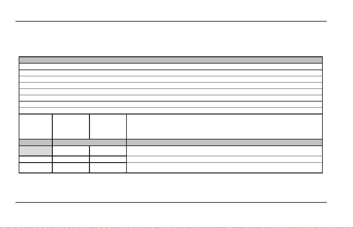
Inspection Maintenance Schedule. . . . . . . . . . . . . . . . . . . . . . . . . . . . . . . . . . . . . . . . . . . . . . . . . . . . . . . . . . . . . . . . 16
Warranty. . . . . . . . . . . . . . . . . . . . . . . . . . . . . . . . . . . . . . . . . . . . . . . . . . . . . . . . . . . . . . . . . . . . . . . . . . . . . . . . . . . . . 19
4
Page 5

INTRODUCTION
THERMO ASSISTANCE
Thermo Assistance is a multilingual
communication tool designed to put you in direct
contact with an authorised Service Dealer should
you require one.
To use this system, you need the following
information before you call:
• Contact Phone Number
• Type of TK Unit
• Thermostat Setting
• Present Load Temperature
• Probable Cause of Fault
• If the Unit is Under Warranty
• How You Will Pay for the Repair
Refer to the Thermo King Service Directory.
Give the Thermo Assistance Operator your name
and a contact phone number
to call you back. Thermo Assistance will then call
you back, at which point you can give details of
the service required and the repair will be
organised.
Please note that Thermo Assistance cannot
guarantee payments and that the service is
designed for the exclusive use of refrigerated
transporters using products manufactured by
Thermo King Corporation.
and ask the operator
DISCLAIMER
The manufacturer, Thermo King Corporation,
assumes no responsibility for any act or action
taken on the part of the owner or operator in the
operation of the products covered by
repair or
this manual that are contrary to the
manufacturer’s printed instructions. No
warranties express or implied, including
warranties arising from cause of dealing or usage
or trade, are made regarding the information,
recommendations, and description contained
herein. The manufacturer is not responsible and
will not be held liable in contract or in tort
(including negligence) for any special, indirect,
or consequential damages, including injury or
damage caused to vehicles, contents, or persons,
by reason of the installation of any Thermo King
product, its mechanical failure, or the failure of
the owner/operator to heed caution and safety
decals strategically located on the product.
INTRODUCTION
Thermo King Spain has developed a new digital
Control Box with a programmable microprocessor
that monitors the operation of the unit and
displays this information rapidly and clearly on
the screen.
These new In-cab Control Boxes have been
designed for use in Thermo King eC-Series units.
There is nothing complicated about learning to
use the In-cab Control Boxes manufactured by
Thermo King Spain, but you will find that a few
minutes spent studying the contents of this manual
will be time well spent.
The In-cab Control Boxes can operate with both
12 and 24V units.
Temperatures can be displayed in either degrees
Celsius or degrees Fahrenheit.
This driver’s manual is published for information
purposes only and the information being furnished
herein should not be considered as all-inclusive
meant to cover all contingencies. If
or
information is required, consult your
further
Thermo King Service Directory for the location
and phone number of your local dealer.
All service requirements, major and minor, should
be handled by a Thermo King dealer for four very
important reasons:
1. They are equipped with the factory
recommended tools to perform all service
functions.
2. They have factory trained and certified
technicians.
5
Page 6
INTRODUCTION
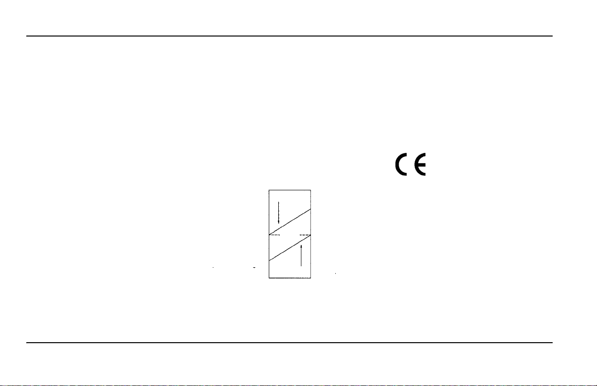
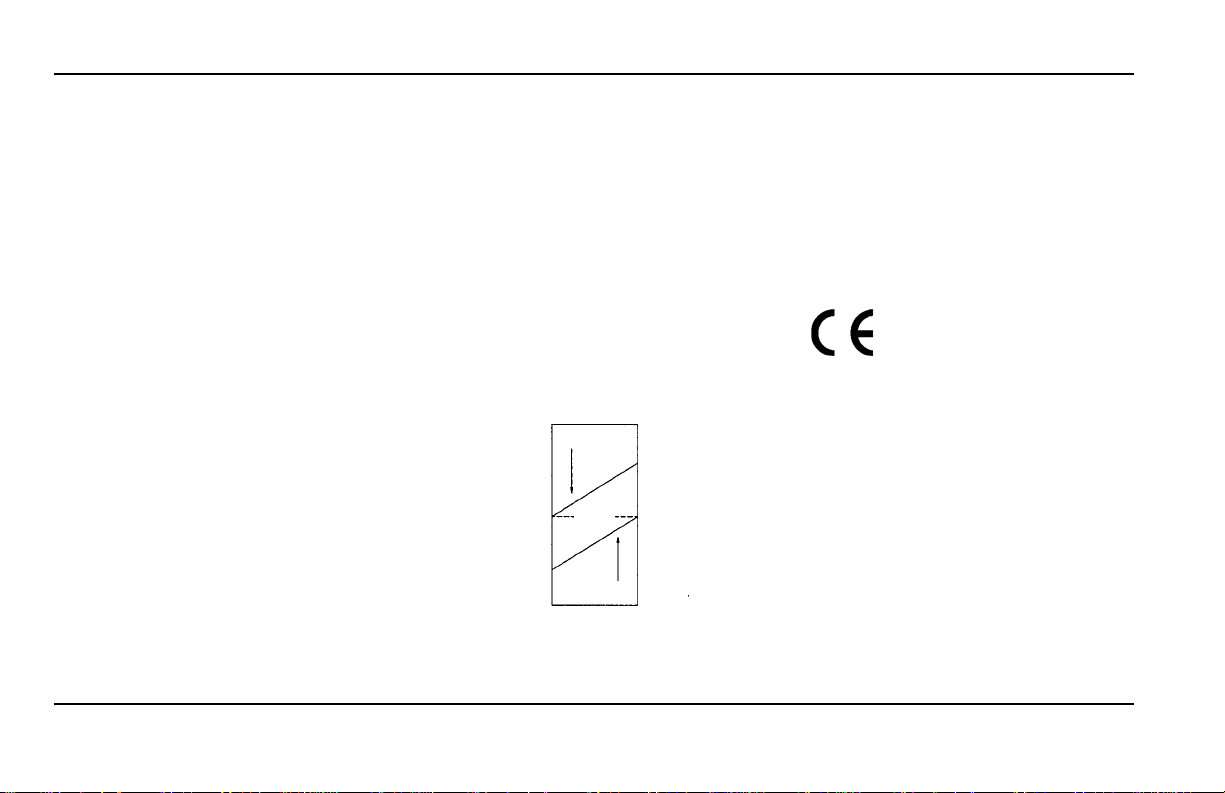
Decrease in
Temperature
Temperature
Setpoint
Increase in
temperature
XºC/F above the
setpoint
XºC/F below the
setpoint
COOL
HEAT
NULL
MODE
3. They are stocked with genuine Thermo King
replacement parts.
4. The warranty on your new unit is valid when
the repair and/or replacement of component
parts is performed by an Authorised
King dealer.
Thermo
Performing pre-trip checks on a regular basis will
minimise “on the road” operating problems. A
closely followed maintenance program will also
help keep your unit in
factory recommended procedures are followed,
If
top operating condition.
you will learn that you have purchased the most
efficient and dependable temperature
system available.
control
GENERAL OPERATION
In truck-driven units, temperature control is based
on two values: The setting (Setpoint) of the
electronic thermostat and the evaporator return
temperature. The difference between these two
temperatures will determine the mode of
operation: cool, heat, or null.
• Cool: When the temperature in the load
compartment is higher than the setpoint, the
unit runs in cool mode to reduce the evaporator
return temperature.
• Heat: When the temperature in the load
compartment is lower than the setpoint, the unit
changes to heat mode to raise the evaporator
return temperature.
• Null: Once the Setpoint Temperature has been
reached, and while the temperature remains
between XºC/F above or below the setpoint,
there is no demand for transfer of heat or cold,
and the unit runs in null mode.
• Defrost: After a scheduled period of time in
cool mode, between 30 minutes and 8 hours,
the unit runs in this fourth mode of operation to
eliminate ice that has accumulated in the
evaporator or condenser coil. Defrost can be
initiated automatically or manually.
Units with R-134a refrigerant without defrost:
Temperatures can be controlled from 0ºC to
+22ºC (+32ºF to +71ºF).
Units with R-134a refrigerant with defrost:
Temperatures can be controlled from -10ºC to
+22ºC (+14ºF to +71ºF).
Units with R-404A refrigerant: Temperatures
be controlled from -32ºC to +22ºC
can
(-26ºF to +71ºF).
Address:
Sant Josep, 140-142 P.I. “El
Pla”, Sant Feliu de Llobregat,
Barcelona, Spain.
Year of manufacture: Reference Serial Plate.
Installation and commissioning are to be carried
out by an authorised Thermo King Dealer in
accordance with Thermo King procedures and
drawings. Exceptions to this with the written
authorisation of the manufacturer only.
6
Factory setting for X is 3ºC (5ºF). During unit
installation, this value can be adjusted in
increments of 1ºC/F.
Page 7

SAFETY PRECAUTIONS
SAFETY PRECAUTIONS
WARNING!
This unit is not intended for use by persons
(including children) with a physical, sensory or
mental impairment, or by persons without the
proper experience or knowledge, unless they
have been provided supervision or instruction
regarding the use of the unit by a person
responsible for their safety.
Children must be supervised to ensure they do
not play with the unit.
Thermo King recommends that all services be
performed by a Thermo King dealer. However,
there are several general safety practices which
you should be aware of:
1. When working with or around the refrigeration
system, always wear goggles or safety glasses.
Refrigerant or battery acid can cause permanent
damage if they come in contact with your eyes.
2. Never run the unit with the compressor
discharge valve closed.
3. Keep your hands and loose clothing clear of
fans and belts at all times when the unit is
running or when opening and closing the
compressor service valves.
4. If you need to drill holes in your unit for any
reason, use extreme caution. You could be
weakening structural components. Drilling
electrical wiring or refrigerant lines could cause
a fire.
into
5. It is recommended that any service work on
evaporator or condenser coils be left for the
certified Thermo King technician but, should
you need to work around the coils, use extreme
caution as exposed coil fins can cause painful
lacerations.
REFRIGERANT
Although fluorocarbon refrigerants are classified
as safe, observe caution when working with
refrigerants or around areas where they are being
used in the servicing of your unit.
Fluorocarbon refrigerants evaporate rapidly,
freezing anything they contact if accidentally
released into the atmosphere from the liquid state.
The Fluorocarbon refrigerants used in the air
conditioning units may produce toxic gases
which, in the presence of an open flame or
electrical short, become severe respiratory
irritants capable of causing death.
FIRST AID - REFRIGERANT
EYES: If liquid comes into contact with the eyes,
flush with large amounts of water and get prompt
medical attention.
SKIN: Flush affected area with large amounts of
lukewarm water and keep cool. Cover burns with
dry, sterile, bulky dressings to protect from
infection or injury. Get medical attention.
INHALATION: Move victim to fresh air and
restore breathing if necessary. Stay with victim
until arrival of emergency medical personnel.
REFRIGERANT OIL
Always observe the following directions when
working with refrigerant oil:
EYES: Do not allow refrigerant oil to contact
your eyes.
SKIN: Do not allow prolonged or repeated contact
with skin or clothing.
IRRITATION: To prevent irritation, wash
thoroughly immediately after handling.
FIRST AID - REFRIGERANT OIL
EYES: Immediately flush eyes with large amounts
of water for at least 15 minutes while holding the
eyelids open. Get prompt medical attention.
SKIN: Remove contaminated clothing. W ash
thoroughly with soap and water. Get medical
attention if the irritation persists.
INHALATION: Move victim to fresh air and
restore breathing if necessary. Stay with victim
until arrival of emergency personnel.
INGESTION: Do not induce vomiting. Contact
local poison control centre or physician
immediately.
7
Page 8

SAFETY PRECAUTIONS
Fluorocarbon refrigerants tend to displace air and
can cause oxygen depletion which could result in
death by suffocation. Observe caution at all times
when working with or around refrigerants, or air
conditioning systems containing refrigerants,
especially in enclosed or confined areas.
AUTO START
Thermo King truck powered refrigeration units
may start up automatically at any time.
Ensure that the unit is switched off before
inspecting any component part.
ELECTRICAL HAZARD
Ensure that high voltage energy supply is
switched off and disconnect the electric cable
before working on the unit. Units with electrical
power supply present a potential electrical hazard.
Electric welding generates high ampere
currents which can damage electrical and
electronic components. To minimise damage,
prior to any welding operation on the ve hicle,
the microprocessor controller and unit battery
must be electrically disconnecte d from
the vehicle. Turn off the microprocessor’s
On/Off switch. Remove the battery negative
cable. Remove all connectors from the rear of
the microprocessor controller. Close the
control box. Connect the welder ground cable
as close as possible to the area being welded.
When welding is complete, remove the welder
ground cable. Reconnect the cables to the rear
of the microprocessor controller. Reconnect
the battery negative cable. Turn on the
microprocessor’s On/Off switch. Reset all
alarms and codes to their previous settings.
Run a full Pre-trip Inspection. Detailed
instructions can be found in Thermo King
Service Procedure A26A.
WARNING
8
Page 9

ELECTRONIC CONTROL SYSTEM
Thermo King direct drive refrigeration units are
composed of a condenser unit, an evaporator
unit, a vehicle compressor and a control panel (Incab Control Box) which operates the unit.
The Electronic Control System is composed of an
Electronic Control Module (located inside the
condenser unit) and the In-cab Control Box. This
In-cab Control Box allows the truck driver to
operate the Thermo King refrigeration unit.
In-cab Control Box
DESCRIPTION OF THE ELECTRONIC CONTROL SYSTEM
The Electronic Control System has the following
characteristics:
• Auto Start
• Delayed Start
• Active Display
• Low Battery Voltage Alarm
• Battery voltage value display
• Unit Control without In-cab Control Box
• Manual or Automatic Defrost
• Return Air Temperature Sensor
• Setpoint Temperature Reading
Auto Start: In case of power shut off, if the unit
was on, the unit will come back on again when the
power is re-started.
Delayed Start:After an automatic start-up, the unit
will remain inactive for few seconds.
Active Display: The In-cab Control Box display is
always active except when the unit is
disconnected (no power) or when the unit is
connected but has been manually switched off
from the In-cab Control Box (when there is no
active alarm).
Total Hourmeter: Total number of hours the unit
is in operation.
Vehicle Compressor Hourmeter: Number of
hours the unit has been operating on-the-road.
Low Battery Voltage Alarm: Disconnects the unit
when the battery voltage is too low.
ELECTRONIC CONTROL SYSTEM
Battery voltage valu e display:The battery
voltage value is displayed in the information
menu.
Unit Control without In-cab Control Box: The
unit can also be operated by the Electronic
Control System without the In-cab Control Box,
under conditions selected by the In-cab Control
Box before it is disconnected.
Manual or Automatic defrost: It is possible to
choose between manual or automatic defrost and
to select the defrost time interval in auto defrost
mode.
Return Air Temperature Sensor: On-screen
reading of the temperature in the load
compartment.
Setpoint Temperature Reading: On-Screen
Setpoint Temperature Reading.
9
Page 10
ELECTRONIC CONTROL SYSTEM
UNIT CONTROLS
WARNING!
Never operate the unit unless you completely
understand the controls; otherwise serious
injury may occur.
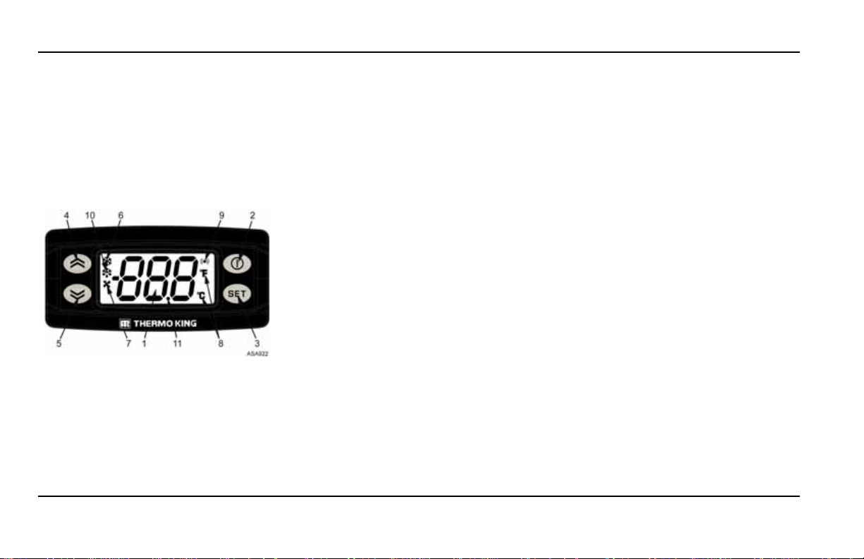
IN-CAB CONTROL BOX
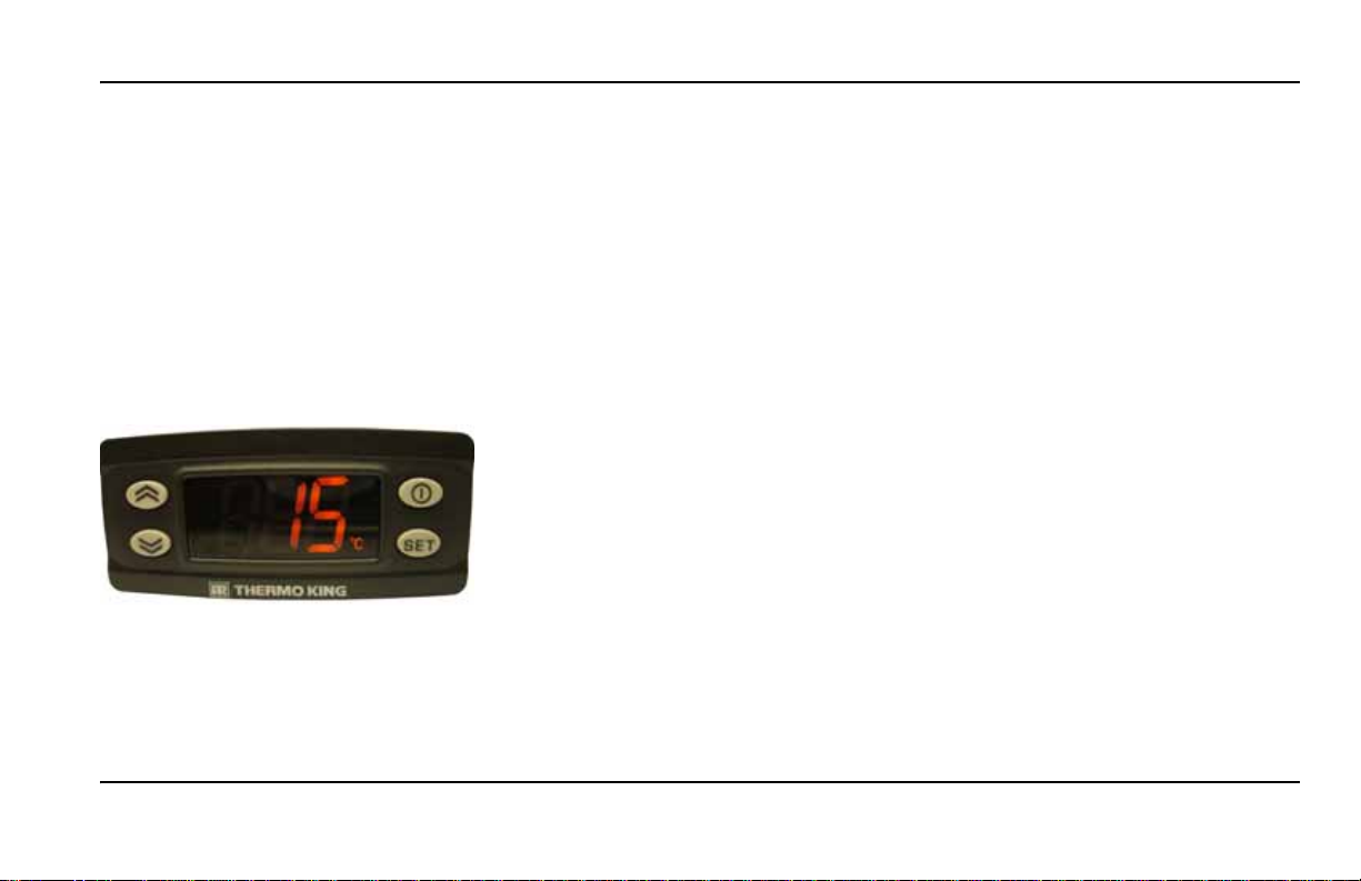
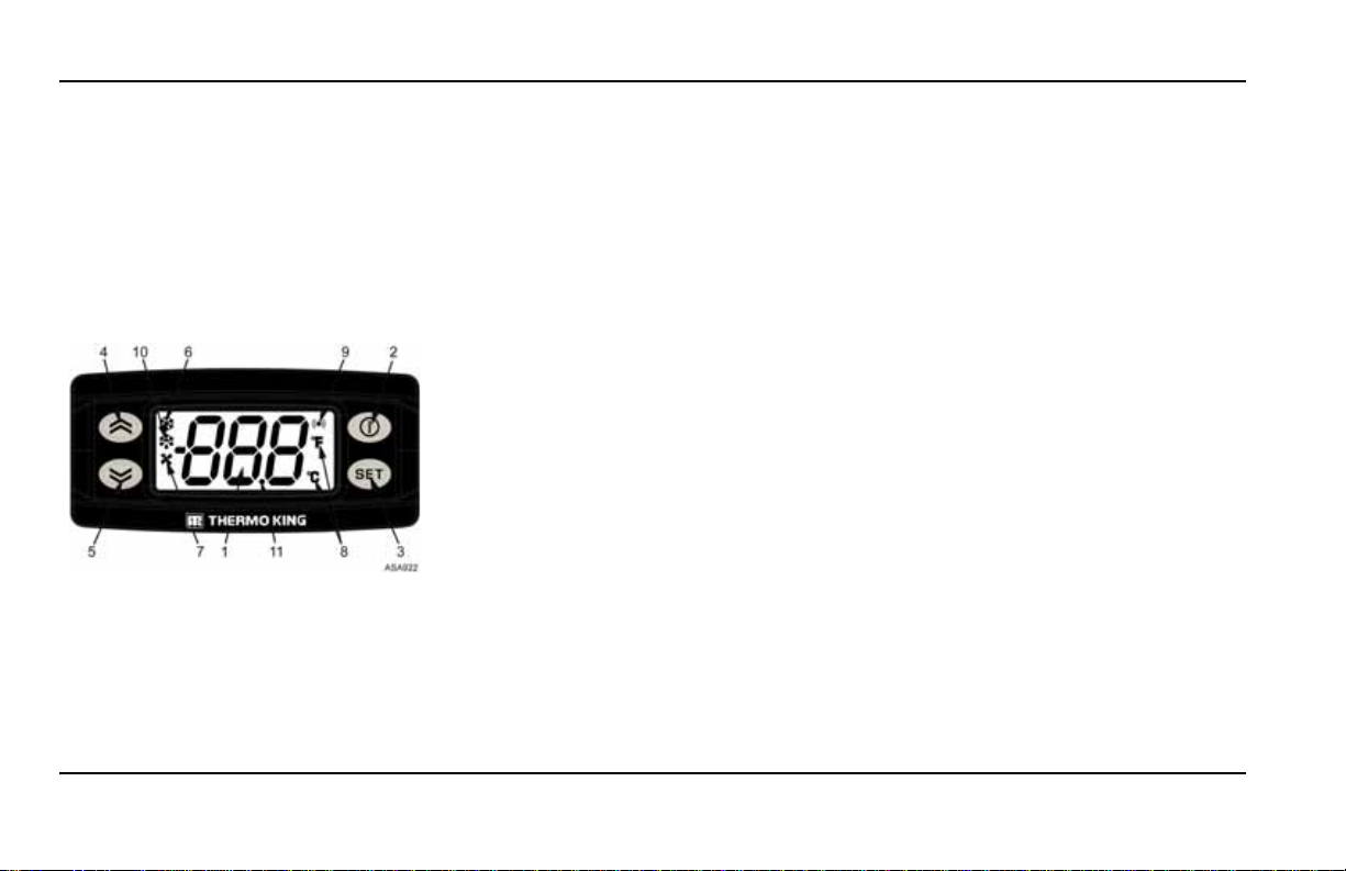
Display, Keys and Symbols
1. Display. It is always active except when the unit
is disconnected (no power) or when the unit is
connected but has been manually switched off
from the In-cab Control Box. It normally displays
the return air temperature.
2. ON/OFF Key. This key is used to start/stop the
unit by holding the key down for at least 1 second.
Single press for exit to the previous level menu.
3. Set Key. Selects prompt screens and
information screens. Single press: enter the next
level menu.
4. Up Key. Is used to increase the setpoint
temperature, display values, and for menu scroll
up.
5. Down Key. Is used to reduce the setpoint
temperature, display values, and for menu scroll
down.
6. Cool Symbol. The unit is cooling.
7. Heat Symbol. The unit is heating.
8. ºC/ºF Display. Indicates whether the on-screen
temperature reading is in degrees Celsius (ºC) or
degrees Fahrenheit (ºF).
9. Alarm Symbol. Indicates that there is an alarm
in the system.
10. Defrost Symbol. Indicates the evaporator unit
is in Defrost Mode.
11. Dot Symbol (decimal). Indicates power
presence, only when unit is off.
10
Page 11

OPERATING INSTRUCTIONS
Ensure the following pre-trip inspections are
performed before starting the unit.
WEEKLY PRE-TRIP INSPECTION
The following weekly pre-trip inspection should
be carried out before loading the truck. The
weekly inspection does not replace the regular
maintenance inspections (refer to the section on
the inspection maintenance schedule). However,
is an important part of the preventative
it
maintenance programme designed to prevent
operating problems before they occur.
1. Leaks. Check for refrigerant leaks and worn
refrigerant lines.
2. Battery. T erminals should be properly tightened
and show no signs of corrosion.
3. Belts. Check for cracks, wear, and proper belt
tension.
4. Mounting bracket. Ensure that bolts are fully
tightened.
5. Electrical system. Electrical connections
should be securely fastened. Wires and terminals
should show no signs of corrosion, cracks or
dampness.
6. Structure. Visually check for physical damage.
7. Coils. The condenser and evaporator coils
should be clean and free of debris.
Washing with clean water should be sufficient.
The use of cleaning agents or detergents is
strongly discouraged due to the possibility of
degradation of the construction. If using a power
washer, the nozzle pressure should not exceed
psi (41 bar). For the best results, spray the coil
600
perpendicular to the face of the coil. The spray
nozzle should be kept between 1 inch and 3 inches
(25 to 75 millimetres) from the coil surface.
If necessary to use a chemical cleaner or detergent
use a cleaner that does not contain any
hydrofluoric acids and is between 7 and 8 on the
pH scale. Ensure dilution instructions provided by
the detergent supplier are followed. In case of
doubt about the compatibility of the detergent
with the type of materials listed above, always ask
the supplier a written confirmation of the
compatibility. Should a chemic al cleaner be
required, it is MANDATOR Y that all components
are thoroughly rinsed with water even if the
instructions of the cleaner specify that it is a “no
rinse” cleaner. Failure to comply with above
mentioned guidelines will lead to a shortened life
of the equipment to an indeterminable degree.
OPERATING INSTRUCTIONS
The repeated transportation of meat and fish waste
can cause extensive corrosion to the evaporator
coils and evaporator section tubing over time due
to ammonia formation and can reduce the lifespan
of the coils. Appropriate additional measures
should be taken to protect the coils against the
aggressive corrosion that can result from
transportation of such products.
8. Load Compartment. Inspect the interior and
exterior of the truck for any damage. Any damage
to the walls or insulation should be repaired.
9. Defrost Drains. Check the defrost drain hoses
and fittings to ensure they are not blocked.
10. Doors. Ensure that doors and weather seals
are in good condition and seal hermetically.
11. Sight gl as s. Check that the refrigerant charge
sight glass on the running unit is totally full (the
cargo compartment temperature must be
approximately 0ºC).
11
Page 12

OPERATING INSTRUCTIONS
STARTING THE UNIT
Engine Operation
1. Start the truck engine. The Dot Symbol will
remain lit.
2. Press the On/Off switch located in the In-cab
Control Box for at least 1 second. The In-cab
Control Box display will be activated.
3. Check the setpoint, and adjust if necessary.
Note: Regular monitoring of the unit is
recommended, the frequency of this monitoring
will depend on the type of cargo.
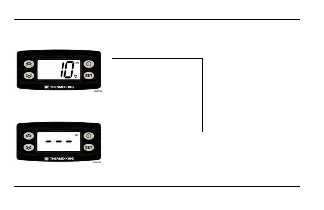
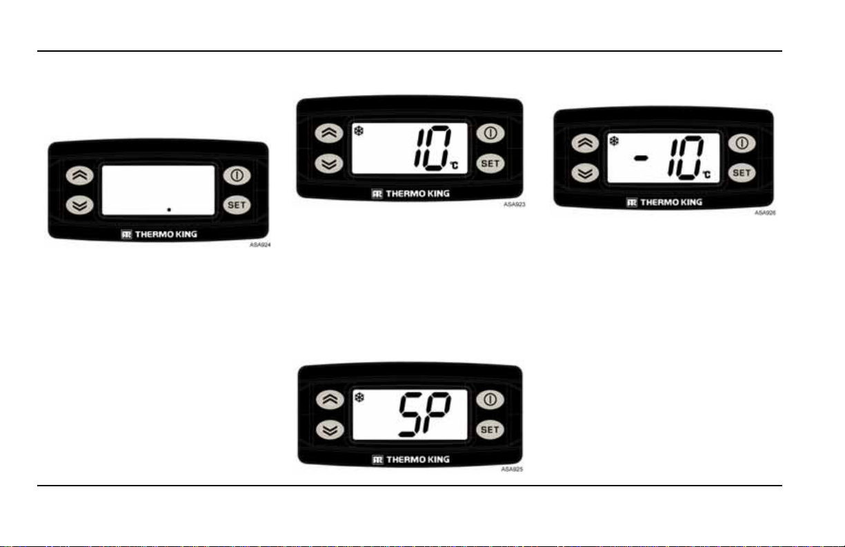
STANDARD DISPLAY
This is the display that appears when the ON/OFF
key is pressed 1 second and the unit started. It
normally displays the return air temperature and
the current operating mode with the appropriate
symbol.
Should there be an alarm, the alarm symbol will
also appear on screen.
The example in the drawing shows: 10ºC
temperature, cool mode.
ENTERING THE SETPOINT TEMPERATURE
The Setpoint Temperature can be quickly and
easily changed.
1. Press and release the SET key once, and the
letters SP will appear on screen.
2. Press SET key again and the current Setpoint
Temperature will appear on screen.
3. Press the UP or DOWN arrow keys to select the
desired Setpoint Temperature. Each time either
of these buttons is pressed and released, the
Setpoint Temperature will change 1 degree.
Setpoint Temperature will also change
continuously if UP/DOWN key is continuously
pressed without release
4. Press and release the SET key to set the
setpoint
5. Press and release ON/OFF key twice to return
to the Standard Display.
CAUTION!
If the SET key is not pressed within 20 se conds
to select the new Setpoint Temperature, the unit
will continue to run at the original Setpoint
Temperature.
12
Page 13
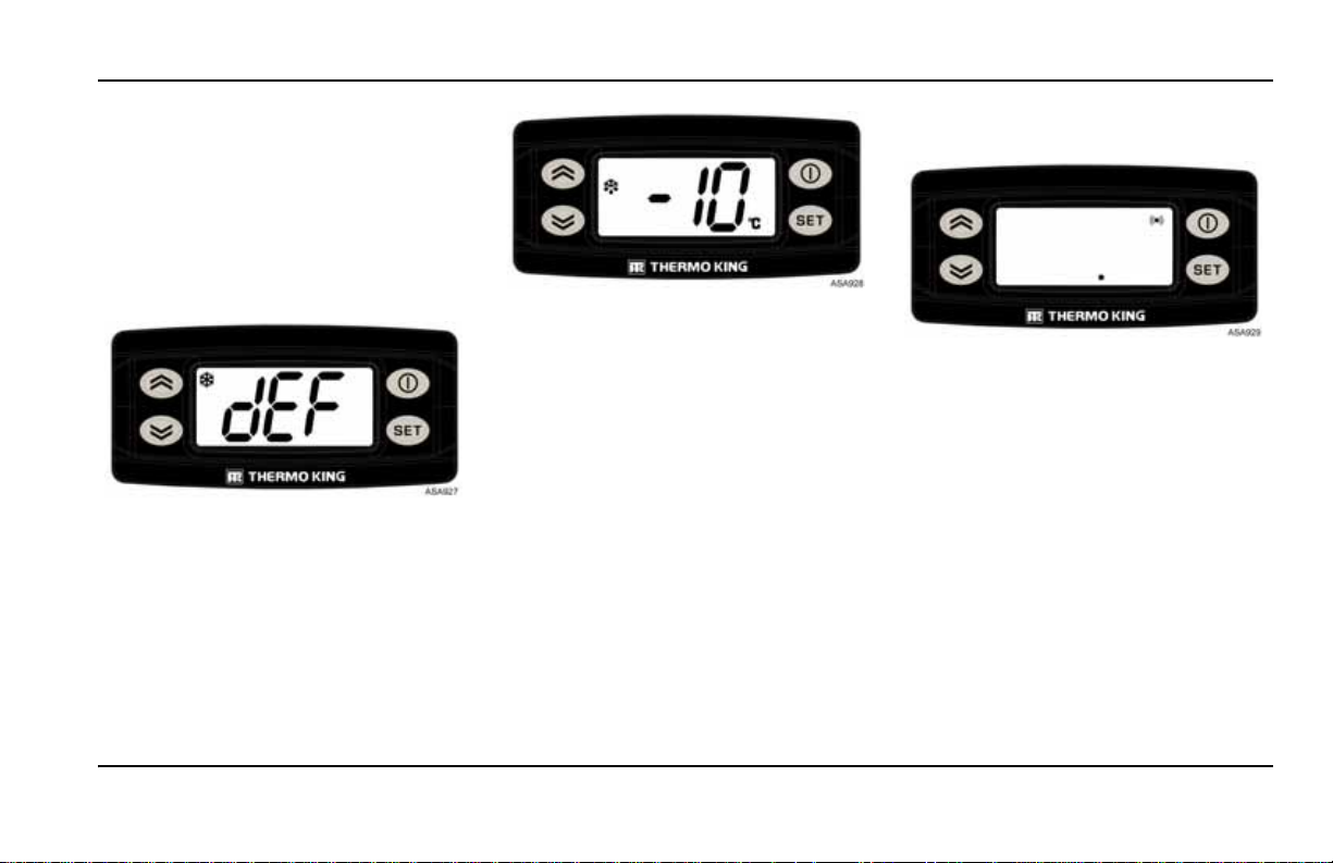
INITIATING THE EVAPORATOR MANUAL DEFROST CYCLE
CAUTION!
Before initiating a manual defrost, ensure that
the unit is not already in a defrost cy cle. When
the unit is in a defrost cycle the defrost symbol
appears on screen.
1. Press and release the SET key once, then press
UP or DOWN and the letters dEF will appear
on screen.
2. To activate manual defrost, press the SET key 3
seconds.
3. Press the ON/OFF key once to return to
STANDARD DISPLAY, where the
the
DEFROST symbol will appear when the
defrost cycle begins (the temperature in the
cargo compartment must be less than 3ºC)
.
Note: for manually disabling the defrost repeat
the same operation.
ALARMS
When the unit is not operating properly, the
microprocessor records the alarm code, alerts the
operator by displaying the ALARM symbol and,
depending on the type of alarm, shuts the unit
down.
There are two alarm categories:
OPERATING INSTRUCTIONS
Manual Start:
The alarm stops the unit, the dot and the ALARM
symbols appears on screen.
Once the alarm condition has been rectified, the
ON/OFF key must be pressed to start up again.
Press and release the SET key twice to display the
current alarm code on screen. If there is more than
one active alarm, all the alarm codes on the unit
can be viewed in sequence by pressing and
releasing the SET and ARROW keys.
13
Page 14
OPERATING INSTRUCTIONS
Auto Start:
The alarm stops the unit, the ALARM symbol
appears on screen and the unit starts up
automatically once the alarm condition has been
rectified.
Should a P1E alarm occur- return air temperature
read error alarm code - appear, --- will appear on
screen together with the alarm symbol, instead of
the return air temperature reading.
Press and release the SET key twice to display the
current alarm code on screen. If there is more than
one active alarm, all the alarm codes on the unit
can be viewed in sequence by pressing and
releasing the SET and ARROW keys.
ALARM CODE DESCRIPTIONS
Manual Start
bAt Low Battery Voltage. Unit and
battery protection system.
Auto Start
P1E Cargo Box Return Air T emperatur e
Reading Error (open circuit or
short-circuit). Contact your Service
Dealer.
E7 Communications Failure (It is not
possible to read any value from the
In-cab, but the unit continues to
work with previous operating
command). Contact your Service
Dealer.
CLEARING ALARM CODES
The alarm condition in the unit must first be
cleared. After clearing the alarm condition, press
and release once the SET key to remove existing
ALARM codes. The standard display will appear
once the ALARM codes have been cleared.
VIEWING INFORMATION SCREENS
MAIN MENU
From the Standard Display use the SET key to
open the Main Menu, then use the ARROW keys
to display:
1. Alarms (if any active)
2. Temperature Setpoint
3. Evaporator Manual Defrost
Press ON/OFF key once to return to Standard
Display
INFORMATION MENU
From the Standard Display press the UP key for
1 second to open the Information Menu, then use
the SET key to display:
1. tSt: Display test (all icons on)
2. reL: Software version
3. bAt: Current battery voltage
4. toH: The total amount of time the unit has been
switched on protecting the load.
5. coH: Engine-driven compressor operating
hours.
Return to Main Menu by pressing ON/OFF key.
14
Page 15

OPERATING INSTRUCTIONS
Note: Each Hour counter will be displayed in
hours when the counted value is <1000.
When the value will be >= 1000, the hours
number will be displayed alternatively between
hours and thousands, into “toh” or “coh”
folders.
For instance, if the counted value is 12055,
“055” will be displayed alternatively with “12”,
where the number with 3 digits is always the
number of “hours”, the number with 2 digits is
always the number of “thousand of hours”.
POST-START INSPECTION
Thermostat. Adjust the thermostat setting to
above and below the compartment temperature
check thermostat operation (see Operating
to
Modes).
Pre-cooling. With the thermostat set at the desired
temperature, run the unit for half-an-hour to one
hour (or longer if possible) before loading the
truck. Pre-cooling eliminates residual heat and
acts as a good test of the refrigeration system.
Defrost. When the unit has finished pre-cooling
the truck interior - the evaporator temperature
should have dropped below 2ºC (35.6ºF) - initiate
a defrost cycle with the manual defrost switch.
The defrost cycle should stop automatically.
LOADING PROCEDURE
1. To minimise frost accumulation in the
evaporator coil and a heat increase inside the
load compartment, ensure that the unit is OFF
before opening the doors. (The unit may
continue to run when the truck is being loaded
in a warehouse with the doors closed.)
2. Carefully check and record the load
temperature when loading the truck. Note
whether any products are out of temperature
range.
3. Load the product in such a way that there is
sufficient space for the air to circulate
throughout the load. DO NOT block the
evaporator inlet or outlet.
4. Product should be pre-cooled before loading.
Thermo King units are designed to maintain the
load at the temperature at which it is loaded.
Transport refrigeration units are not designed to
reduce the load temperature.
PROCEDURE AFTER LOADING
1. Ensure that all doors are closed and locked.
2. Adjust the thermostat to the desired
temperature setpoint.
3. Start the unit.
4. Half an hour after loading the truck, defrost the
unit for a moment by pressing the Manual
Defrost switch. If the coil temperature drops to
below 2ºC (35.6ºF), the unit will defrost. The
defrost cycle should stop automatically.
WEEKLY PRE-TRIP CHECKS
1. Visually inspect belt.
2. Listen for unusual noises, vibrations, etc.
3. Visually inspect unit for fluid leaks (coolant,
oil, refrigerant).
4. Visually inspect unit for damaged, loose or
broken parts (including air ducts and
bulkheads, if so equipped).
5. In the event of excess of dirt or obstruction
clean the unit, including condenser and
evaporator coils.
WEEKLY POST-TRIP CHECKS
1. Clean the outside cover of the unit. Use a damp
cloth and neutral detergents. Do not use harsh
cleaning products or solvents.
CAUTION!
Do not use pressurised water.
2. Check for leaks.
3. Check for loose or missing hardware.
4. Check for physical damage to the unit.
15
Page 16
INSPECTION MAINTENANCE SCHEDULE
UNIT MODELS Vehicle Powered Range
First Week Inspection Recommended
AFTER FIRST WEEK of operation:
•
Check belt tension
• Tighten unit and mount bracket mounting bolts
• Check for chafing of wiring harnesses and all hoses
• Check refrigerant hoses, tubes and fittings for leaks.
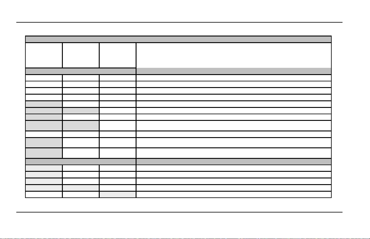
Recommended A B
Every 500 hrs Every 1,500 hrs Every 3,000 hrs
Or Or Or
6 months 12 months 24 months
Miscellaneous These procedures may be carried out as an addition to the standard service procedures
5 5
* Check calibration of return and discharge sensors as per customers HACCP or annually. Also stand alone
loggers if installed. Testing not included as part of service time.
5 5 5
Check operation of all accessories.
5 5 5
Check service records and ensure all service and warranty modifications have been completed. (Updates not
included).
Inspect/repair the following items
INSPECTION MAINTENANCE SCHEDULE
A closely followed maintenance program will also help to keep your Thermo King unit in top op erating condition. The following general schedule is provided
to assist in monitoring that maintenance.
16
Maintenance actions should be performed where applicable depending on the model.
Page 17

INSPECTION MAINTENANCE SCHEDULE
UNIT MODELS Vehicle Powered Range
Recommended A B
Every 500 hrs Every 1,500 hrs Every 3,000 hrs
Or Or Or
6 months 12 months 24 months
Electrical
5 5 5
Download Datalogger - Check alarm for codes and system operation and function & take corrective action as
required (where applicable)
5 5 5
Check defrost initiation and termination. Check evaporator fans function during defrost (fans should be stopped
during defrost)
5 5 5
Check thermostat switch sequence.
5 5
Check the safety devices in the closing circuits.
5 5
Check thermostat and temperature sensor calibration.
5 5
Check for loose wires or plug connections.
5 5 5
Check wiring and harnesses for chafing
5 5 5
Check operation of condenser and evaporator fans
5 5
Inspect DC motor brushes. Replace them before 2,000 HRS. (If the next service inspection is going to exceed
the 2000hrs change them at this inspection)
5 5 5
Check operation of all Thermo King external accesory equipment.
5 5 5
Check operation of all non Thermo King external accesory equipment.
Structure
5 5 5
Visually inspect the unit for damaged, loose or broken parts.
5 5
Clean defrost drains.
5 5
Clean the evaporator and condenser coils and the heat sink of the bridge rectifier.
5 5
Check all mounting bolts, brackets, lines, hoses, etc.
Inspect/repair the following items
The service technician is responsible for assessing the condition of all parts & components found, during any service operation, to be in a
condition suitable for further operation up to the next scheduled service. If parts are not considered to be in a suitable condition, they should be
replaced.
17
Page 18
INSPECTION MAINTENANCE SCHEDULE
UNIT MODELS Vehicle Powered Range
Recommended A B
Every 500 hrs Every 1,500 hrs Every 3,000 hrs
Or Or Or
6 months 12 months 24 months
Refrigeration
5 5 5
Visually inspect refrigerant hoses, tubes and fittings for leaks.
5 5 5
Visually inspect refrigerant hoses, tubes and fittings for rubbing.
5 5 5
Check routing of refrigerant hoses in road compressor.
5 5 5
Check refrigerant charge.
5 5
Check preassure regulator valves
5
Replace dehydrator.
5 5
Inspect oil separator.
5
Check the compressor’s suction inlet filter when replacing drier. (Or if system is opened for other reason)
5 5 5
Check operation of compressor clutches
5 5
Check and ensure temperature change during heating and cooling cycles. (heating where applicable)
5 5
Check validity of F Gas certificate as per local regulations. (Certification is not included as part of the
Preventative Maintenance).
Drive Kit Adapter (Refer to manufacturer maintenance recomendations)
5 5
Visually inspect the compressor mount kit and associated components.
5 5
Check that all adapter bolts are properly tightened.
5 5
Check that there are no abnormal vibrations.
5
Replace the belt according to manufacturer recommendations.
5 5
Inspect the belts for condition and tension according to manufacturer recommendations.
Inspect/repair the following items
18
Page 19
WARRANTY
WARRANTY
Should you require warranty service or repair
during the warranty period, simply present your
copy of the Warranty Certificate at any of the
dealer locations shown in the Thermo King
Service Directory. They will be happy to help
in accordance with the summary below.
you
WARRANTY SUMMARY
Full terms of the Thermo King Limited Warranty
are available from your Thermo King dealer.
Note: Parts replacements or repairs under
warranty must be performed by an authorised
Thermo King dealer.
Note: Warranty term and times are subject to
change. The specific warranty which applies to
your unit can be checked by your Thermo King
dealer.
RECOVER REFRIGERANT
At Thermo King we recognise the need to
preserve the environment and limit the potential
the ozone layer that can result from
harm to
allowing refrigerant to escape into the
atmosphere. We strictly adhere to a policy that
promotes the
refrigerant into the atmosphere.
recovery and limits the loss of
19
Page 20

WARRANTY
20
Page 21

Manuel de l’utilisateur de la série Ce
TK 60980-FR-18-OP (Rév. 3, 04/16)
Page 22

FRANÇAIS TABLE DES MATIÈRES
Introduction . . . . . . . . . . . . . . . . . . . . . . . . . . . . . . . . . . . . . . . . . . . . . . . . . . . . . . . . . . . . . . . . . . . . . . . . . . . . . . . . . . 23
Fonctionnement général. . . . . . . . . . . . . . . . . . . . . . . . . . . . . . . . . . . . . . . . . . . . . . . . . . . . . . . . . . . . . . . . . . . . . . . . . . . .24
Mesures de sécurité . . . . . . . . . . . . . . . . . . . . . . . . . . . . . . . . . . . . . . . . . . . . . . . . . . . . . . . . . . . . . . . . . . . . . . . . . . . 25
Fluide frigorigène . . . . . . . . . . . . . . . . . . . . . . . . . . . . . . . . . . . . . . . . . . . . . . . . . . . . . . . . . . . . . . . . . . . . . . . . . . . . . . . . .25
Premiers secours - Fluide frigorigène . . . . . . . . . . . . . . . . . . . . . . . . . . . . . . . . . . . . . . . . . . . . . . . . . . . . . . . . . . . . . . . . .25
Huile de réfrigération . . . . . . . . . . . . . . . . . . . . . . . . . . . . . . . . . . . . . . . . . . . . . . . . . . . . . . . . . . . . . . . . . . . . . . . . . . . . . .25
Premiers secours - Huile de réfrigération. . . . . . . . . . . . . . . . . . . . . . . . . . . . . . . . . . . . . . . . . . . . . . . . . . . . . . . . . . . . . . .26
Démarrage automatique. . . . . . . . . . . . . . . . . . . . . . . . . . . . . . . . . . . . . . . . . . . . . . . . . . . . . . . . . . . . . . . . . . . . . . . . . . . .26
Risques d’électrocution . . . . . . . . . . . . . . . . . . . . . . . . . . . . . . . . . . . . . . . . . . . . . . . . . . . . . . . . . . . . . . . . . . . . . . . . . . . .26
Système de commande électronique . . . . . . . . . . . . . . . . . . . . . . . . . . . . . . . . . . . . . . . . . . . . . . . . . . . . . . . . . . . . . 27
Description du système de commande électronique . . . . . . . . . . . . . . . . . . . . . . . . . . . . . . . . . . . . . . . . . . . . . . . . . . . . . .27
Commandes du groupe . . . . . . . . . . . . . . . . . . . . . . . . . . . . . . . . . . . . . . . . . . . . . . . . . . . . . . . . . . . . . . . . . . . . . . . . . . . .28
Instructions d’utilisation. . . . . . . . . . . . . . . . . . . . . . . . . . . . . . . . . . . . . . . . . . . . . . . . . . . . . . . . . . . . . . . . . . . . . . . . 29
Inspection hebdomadaire avant-trajet . . . . . . . . . . . . . . . . . . . . . . . . . . . . . . . . . . . . . . . . . . . . . . . . . . . . . . . . . . . . . . . . .29
Démarrage du groupe . . . . . . . . . . . . . . . . . . . . . . . . . . . . . . . . . . . . . . . . . . . . . . . . . . . . . . . . . . . . . . . . . . . . . . . . . . . . .30
Écran d’affichage standard. . . . . . . . . . . . . . . . . . . . . . . . . . . . . . . . . . . . . . . . . . . . . . . . . . . . . . . . . . . . . . . . . . . . . . . . . .30
Entrée de la température du point de consigne . . . . . . . . . . . . . . . . . . . . . . . . . . . . . . . . . . . . . . . . . . . . . . . . . . . . . . . . . .30
Initialisation du cycle de dégivrage manuel de l’évaporateur. . . . . . . . . . . . . . . . . . . . . . . . . . . . . . . . . . . . . . . . . . . . . . . .31
Alarmes . . . . . . . . . . . . . . . . . . . . . . . . . . . . . . . . . . . . . . . . . . . . . . . . . . . . . . . . . . . . . . . . . . . . . . . . . . . . . . . . . . . . . . . .31
Descriptions des codes d’alarme . . . . . . . . . . . . . . . . . . . . . . . . . . . . . . . . . . . . . . . . . . . . . . . . . . . . . . . . . . . . . . . . . . . . .32
Suppression des codes d’alarme. . . . . . . . . . . . . . . . . . . . . . . . . . . . . . . . . . . . . . . . . . . . . . . . . . . . . . . . . . . . . . . . . . . . .32
Visualisation des écrans d’information. . . . . . . . . . . . . . . . . . . . . . . . . . . . . . . . . . . . . . . . . . . . . . . . . . . . . . . . . . . . . . . . .32
Inspection post-démarrage. . . . . . . . . . . . . . . . . . . . . . . . . . . . . . . . . . . . . . . . . . . . . . . . . . . . . . . . . . . . . . . . . . . . . . . . . .33
Procédure de chargement . . . . . . . . . . . . . . . . . . . . . . . . . . . . . . . . . . . . . . . . . . . . . . . . . . . . . . . . . . . . . . . . . . . . . . . . . .33
Procédure après chargement. . . . . . . . . . . . . . . . . . . . . . . . . . . . . . . . . . . . . . . . . . . . . . . . . . . . . . . . . . . . . . . . . . . . . . . .33
Vérifications hebdomadaires avant-trajet. . . . . . . . . . . . . . . . . . . . . . . . . . . . . . . . . . . . . . . . . . . . . . . . . . . . . . . . . . . . . . .33
Vérifications hebdomadaires après-trajet. . . . . . . . . . . . . . . . . . . . . . . . . . . . . . . . . . . . . . . . . . . . . . . . . . . . . . . . . . . . . . .33
Calendrier des inspections d’entretien . . . . . . . . . . . . . . . . . . . . . . . . . . . . . . . . . . . . . . . . . . . . . . . . . . . . . . . . . . . . 34
Garantie . . . . . . . . . . . . . . . . . . . . . . . . . . . . . . . . . . . . . . . . . . . . . . . . . . . . . . . . . . . . . . . . . . . . . . . . . . . . . . . . . . . . . 37
22
Page 23

INTRODUCTION
THERMO ASSISTANCE
Thermo Assistance est un outil de communication
multilingue conçu pour vous mettre en contact
direct avec un concessionnaire agréé pour le
service après-vente lorsque vous en avez besoin.
Pour utiliser ce système, vous devez préparer les
informations suivantes avant de passer votre
:
appel
• le numéro de téléphone où vous joindre
• le type de votre groupe TK
• le réglage du thermostat
• la température actuelle du chargement
• la cause probable du prob lème
• si le groupe est sous garantie
• votre mode de paiement pour la réparation
Consultez l’annuaire du service après-vente
King.
Thermo
Laissez vos nom et numéro de téléphone à un
opérateur Thermo
vous rappeler. Un opérateur Thermo
vous rappellera et vous pourrez alors lui donner
les détails du service requis afin que la réparation
puisse être organisée.
Veuillez noter que Thermo Assistance ne peut pas
garantir les paiements et que ce service est destiné
exclusivement aux transporteurs frigorifiques
utilisant des produits fabriqués par
Thermo King Corporation.
Assistance et demandez-lui de
Assistance
DÉCHARGE DE RESPONSABILITÉ
Le fabricant, Thermo King Corporation, ne
saurait être tenu pour responsable de toute action
ou de tout acte entrepris par le propriétaire ou
l’utilisateur lors de la réparation ou de
l’utilisation des produits couverts dans ce
manuel, qui serait contraire aux instructions
imprimées par le fabricant. Aucune garantie,
expresse ou implicite, y compris les garanties
concernant toute transaction, usage ou
commercialisation, n’est fournie pour ce qui est
des informations, des recommandations et de la
description figurant dans le présent document.
Le fabricant n’est pas responsable et ne saurait
être tenu pour responsable, par contrat ou acte
dommageable (y compris la négligence), de tout
dommage déterminé, indirect ou consécutif, y
compris les préjudices ou les dommages causés
aux véhicules, au contenu ou aux personnes,
résultant de l’installation de tout produit
King, de sa défaillance mécanique ou du
Thermo
non-respect par le propriétaire/l’utilisateur des
instructions de sécurité figurant sur les
autocollants placés à des endroits clés du produit.
INTRODUCTION
Thermo King Spain a mis au point un nouveau
boîtier de commande numérique doté d’un
microprocesseur programmable qui surveille le
fonctionnement du groupe et affiche rapidement et
clairement à l’écran les informations associées.
Ces nouveaux boîtiers de commande en cabine
ont été conçus pour les groupes Thermo
Ec.
la série
L’utilisation des boîtiers de commande en cabine
fabriqués par Thermo
compliqué, mais vous verrez que consacrer
quelques minutes à l’étude du contenu de ce
manuel ne sera pas du temps perdu.
Les boîtiers de commande en cabine peuvent
fonctionner avec des groupes 12
Les températures peuvent être affichées en degrés
Celsius ou Fahrenheit.
Ce manuel du conducteur est publié uniquement
dans un but informatif. Les renseignements
fournis ne doivent donc en aucun cas être
considérés comme exhaustifs ou couvrant toutes
les éventualités. Pour toute information
complémentaire, veuillez consulter l’annuaire du
service après-vente Thermo
vous trouverez l’adresse et le numéro de
téléphone de votre concessionnaire local.
Toute demande de service après-vente, quelle
qu’en soit l’importance, doit être prise en charge
par un concessionnaire Thermo
raisons essentielles
1. Il est équipé des outils recommandés par
l’usine pour effectuer toutes les opérations
d’entretien.
2. Ses techniciens sont formés en usine et agréés.
King Spain n’a rien de
King dans lequel
:
King de
et 24 V.
King pour quatre
23
Page 24
INTRODUCTION
Diminution de
température
Température du
point de consigne
Augmentation de
température
X ºC au-dessus du
point de consigne
X ºC en dessous du
point de consigne
REFROIDISSEMENT
CHAUFFAGE
MODE
NUL
3. Il possède un stock de pièces de remplacement
King d’origine.
Thermo
4. La garantie couvrant votre nouveau groupe
s’applique lorsque la réparation et/ou le
remplacement des composants sont effectués
par un concessionnaire Thermo
Les problèmes de fonctionnement « sur la route »
peuvent être limités en effectuant régulièrement
des vérifications avant-trajet. En suivant
attentivement le programme d’entretien, vous
pourrez également maintenir votre groupe en
parfait état de fonctionnement. En respectant ainsi
les procédures recommandées par le fabricant,
vous réaliserez que vous avez acheté le système
de contrôle de la température le plus efficace et le
plus fiable qui soit.
FONCTIONNEMENT GÉNÉRAL
Dans les groupes alimentés par le camion, le
contrôle de la température dépend de deux
: le réglage (Point de consigne) de la
valeurs
température de retour du thermostat électrique et
celui de l’évaporateur. La différence entre ces
deux températures déterminera le mode de
fonctionnement
ou Nul.
• Refroidissement : lorsque la température dans
le compartiment de chargement est supérieure
au point de consigne, le groupe fonctionne en
mode Refroidissement afin de réduire la
température de retour de l’évaporateur.
24
: Refroidissement, Chauffage
King agréé.
•
Chauffage :
lorsque la température dans le
compartiment de chargement est inférieure au point
de consigne, le groupe passe en mode Chauffage
afin d’augmenter la température de retour de
l’évaporateur.
•
Nul :
une fois la température du point de consigne
atteinte, et tant que la température reste à X ºC audessus ou en dessous du point de consigne, il
n’existe aucune demande de transfert de chaleur ni
de froid, et le groupe fonctionne alors en mode Nul.
•
Dégivrage :
refroidissement comprise entre 30
après une période planifiée en mode de
minutes et
8 heures, le groupe passe à ce quatrième mode de
fonctionnement afin d’éliminer la glace accumulée
dans le serpentin de l’évaporateur ou du
condenseur. Le dégivrage peut être lancé
automatiquement ou manuellement.
Le réglage d’usine pour X est de 3 ºC. Cette
valeur peut être ajustée par palier de 1
°C pendant
l’installation du groupe.
Groupes avec fluide frigorigène R-134a sans
dégivrage : les températures peuvent être
contrôlées de 0
Groupes avec fluide frigorigène R-134a avec
dégivrage : les températures peuvent être
contrôlées de -10
Groupes avec fluide frigorigène R-404A :
ºC à +22 ºC.
ºC à +22 ºC.
les températures peuvent être contrôlées de -32 ºC
+22 ºC.
à
Adresse :
Sant Josep, 140-142 P.I.
El Pla », Sant Feliu de
«
Llobregat, Barcelone,
Espagne.
Année de fabrication : Plaque signalétique de
référence.
L’installation et la mise en service doivent être
effectuées par un concessionnaire Thermo
King
agréé, en accord avec les procédures et les
schémas Thermo
King. Toute exception à cette
règle doit impérativement faire l’objet d’une
autorisation écrite du fabricant.
Page 25

MESURES DE SÉCURITÉ
MESURES DE SÉCURITÉ
AVERTISSEMENT !
Le groupe n’est pas conçu pour être utilisé par
des personnes (y compris des enfants)
souffrant de déficiences physiques,
sensorielles ou mentales, ni par des personnes
dépourvues de l’expérience ou des
connaissances adéquates, à moins d’être sous
la supervision ou d’avoir reçu des instructions
concernant l’utilisation du groupe par une
personne responsable de leur sécurité.
Les enfants doivent rester sous surveillance
pour s’assurer qu’ils ne jouent pas avec
le groupe.
Thermo King recommande que toutes les
opérations d’entretien soient prises en charge par
un concessionnaire Thermo
vous devez connaître quelques mesures générales
de sécurité à observer
1. Portez toujours un masque ou des lunettes de
sécurité lorsque vous travaillez sur ou autour du
système de réfrigération. Le fluide frigorigène
ou l’acide de la batterie peuvent provoquer des
lésions permanentes en cas de contact avec les
yeux.
2. Ne faites jamais fonctionner le groupe lorsque
le clapet de décharge du compresseur est fermé.
3. Veillez toujours à garder les mains et les
vêtements amples à l’écart des ventilateurs et
des courroies lorsque le groupe est en marche
ou lors de l’ouverture et de la fermeture des
vannes de service du compresseur.
King. Cependant,
:
4. Soyez extrêmement prudent si vous devez
percer des trous dans le groupe pour une
quelconque raison. Vous pourriez fragiliser les
composants structurels. Le perçage du câblage
électrique ou des conduites de fluide
frigorigène pourrait déclencher un incendie.
5. Il est recommandé de laisser au technicien
certifié de Thermo
King tout travail d’entretien
à accomplir sur les serpentins de l’évaporateur
ou du condenseur, mais si vous devez travailler
près des serpentins, soyez extrêmement prudent
car les ailettes apparentes des serpentins
peuvent causer des lacérations douloureuses.
FLUIDE FRIGORIGÈNE
Même si les fluides frigorigènes au fluorocarbone
sont classés sans danger, soyez prudent lorsque
vous travaillez avec des fluides frigorigènes ou
près de zones où des fluides frigorigènes sont
utilisés pour l’entretien de votre groupe.
Les fluides frigorigènes au fluorocarbone
s’évaporent rapidement, et gèlent tout ce qu’ils
touchent en cas d’évaporation accidentelle dans
l’atmosphère à partir de l’état liquide.
Les fluides frigorigènes au fluorocarbone utilisés
dans les groupes de climatisation d’air peuvent
produire des gaz toxiques qui, en présence d’une
flamme ouverte ou d’un court-circuit électrique,
se transforment en graves irritants respiratoires
pouvant entraîner la mort.
PREMIERS SECOURS - FLUIDE FRIGORIGÈNE
YEUX : si le liquide entre en contact avec les yeux,
rincez abondamment à l’eau et consultez
rapidement un médecin.
PEAU : rincez abondamment la zone affectée à
l’eau tiède et gardez au frais. Couvrez les brûlures
d’un pansement sec, stérile et épais pour protéger
des infections ou des blessures. Consultez un
médecin.
INHALATION : transportez la victime au grand air
et ranimez-la le cas échéant. Restez auprès de la
victime jusqu’à l’arrivée des secours.
HUILE DE RÉFRIGÉRATION
Respectez toujours les consignes suivantes
lorsque vous travaillez avec de l’huile de
réfrigération
YEUX : ne laissez pas l’huile de réfrigération
entrer en contact avec les yeux.
PEAU : évitez tout contact prolongé ou répété
avec la peau ou les vêtements.
IRRITATION : pour éviter les irritations, lavez
soigneusement immédiatement après
manipulation.
:
25
Page 26

MESURES DE SÉCURITÉ
PREMIERS SECOURS - HUILE DE RÉFRIGÉRATION
YEUX : lavez immédiatement les yeux à grande
eau pendant au moins 15
les paupières ouvertes. Consultez rapidement un
médecin.
PEAU : retirez les vêtements contaminés.
Lavez-vous soigneusement à l’eau savonneuse.
Consultez un médecin si l’irritation persiste.
INHALATION : transportez la victime au grand air
et ranimez-la le cas échéant. Restez aux côtés de
la personne blessée jusqu’à l’arrivée des secours.
INGESTION : ne provoquez pas de vomissements.
Contactez immédiatement le centre antipoison le
plus proche ou un médecin.
Les fluides frigorigènes au fluorocarbone ont
tendance à déplacer l’air et peuvent provoquer un
appauvrissement en oxygène, susceptible
d’entraîner la mort par suffocation. Soyez toujours
prudent lorsque vous travaillez avec ou à
proximité de fluides frigorigènes, ou d’un système
de climatisation contenant des fluides
frigorigènes, notamment dans les espaces clos ou
confinés.
minutes tout en gardant
DÉMARRAGE AUTOMATIQUE
Les groupes de réfrigération Thermo King pour
camions peuvent démarrer automatiquement à
tout moment.
Assurez-vous que le groupe est éteint avant
d’inspecter ses composants.
RISQUES D’ÉLECTROCUTION
Assurez-vous que l’alimentation haute tension est
éteinte et débranchez le câble électrique avant de
travailler sur le groupe. Les groupes dotés d’une
alimentation électrique présentent un risque
électrique potentiel.
Le soudage électrique génère des courants de
forte intensité susceptibles d’endommager les
composants électriques et électr on iq ues. Afin
de limiter les risques de détérioration, le
contrôleur du microprocesseur et la batterie
du groupe doivent être déconnectés
électriquement du véhicule avant toute
opération de soudage sur ce dernier.
Éteignez l’interrupteur Marche/Arrêt du
microprocesseur. Retirez le câble négatif de la
batterie. Retirez tous les connecteurs situés à
l’arrière du contrôleur du microprocesseur.
Fermez le boîtier de commande. Branchez le
câble de mise à la masse de l’équipement de
soudage le plus près possible de la zone à
souder. Lorsque la soudure est terminée,
débranchez le câble de mise à la masse de
l’équipement de soudage. Rebranchez les
câbles à l’arrière du contrôleur du
microprocesseur. Rebranchez le câble négatif
de la batterie. Allumez l’interrupteur Marche/
Arrêt du microprocesseur. Ré init ia lis ez toutes
les alarmes et les codes sur les valeurs de
réglage précédentes. Effectuez une inspection
avant-trajet complète. Les instructions
détaillées sont indiquées dans la procédure
d’entretien Thermo King A26A.
AVERTISSEMENT
26
Page 27
SYSTÈME DE COMMANDE ÉLECTRONIQUE
Les groupes de réfrigération à poulie-moteur de
King sont constitués d’un groupe de
Thermo
condenseur, d’un groupe d’évaporateur, d’un
compresseur de véhicule et d’un panneau de
commande (boîtier de commande en cabine)
contrôler le groupe.
pour
Le système de commande électronique est
constitué d’un module de commande électronique
(situé à l’intérieur du groupe du condenseur) et du
boîtier de commande en cabine. Ce boîtier de
commande en cabine permet au conducteur du
camion de contrôler le groupe de réfrigération
King.
Thermo
Boîtier de commande en cabine
DESCRIPTION DU SYSTÈME DE COMMANDE ÉLECTRONIQUE
Le système de commande électronique présente
les caractéristiques suivantes
• Démarrage automatique
• Démarrage différé
• Affichage actif
• Alarme de tension de la batterie faible
• Affichage de la valeur de tension de la batterie
• Contrôle du groupe sans boîtier de commande
en cabine
• Dégivrage manuel ou automatique
• Capteur de température de retour d’air
• Valeur de température du point de consigne
Démarrage automatique : En cas de panne de
courant, si le groupe était allumé, il redémarrera
une fois le courant rétabli.
Démarrage différé : Après un démarrage
automatique, le groupe restera inactif pendant
quelques secondes.
Affichage actif : L’affichage du boîtier de
commande en cabine est toujours actif sauf
lorsque le groupe est déconnecté (pas
d’alimentation) ou lorsqu’il est connecté mais a
été éteint manuellement à partir du boîtier de
commande en cabine (en l’absence d’alarme
active).
Total du compteur horaire : Nombre total
d’heures de fonctionnement du groupe.
:
SYSTÈME DE COMMANDE ÉLECTRONIQUE
Compteur horaire du compresseu r du véhicule :
Nombre d’heures de fonctionnement du groupe
sur la route.
Alarme de tension de la batterie faible :
Déconnecte le groupe lorsque la tension de la
batterie est trop faible.
Affichage de la valeur de tension de la batterie :
La valeur de tension de la batterie est affichée
dans le menu Informations.
Contrôle du groupe sans boîtier de commande
en cabine : Le groupe peut aussi être contrôlé par
le système de commande électronique sans le
boîtier de commande en cabine, dans les
conditions sélectionnées par le boîtier de
commande avant sa déconnexion.
Dégivrage manuel ou automatique : Il est
possible de choisir un dégivrage manuel ou
automatique et de sélectionner l’intervalle de
temps de dégivrage en mode de dégivrage
automatique.
Capteur de température de retour d’air : Valeur
de température du point de consigne dans le
compartiment de chargement.
Valeur de température du point de consigne :
Valeur de température du point de consigne à
l’écran.
27
Page 28
SYSTÈME DE COMMANDE ÉLECTRONIQUE
COMMANDES DU GROUPE
AVERTISSEMENT !
N’utilisez jamais le groupe à moins que vous
n’en compreniez parfaitement les commandes ;
vous vous exposez sinon à de graves
blessures.
BOÎTIER DE COMMANDE EN CABINE
Affichage, touches et symboles
1. Affichage. Il est toujours actif, sauf lorsque le
groupe est déconnecté (non-alimenté) ou lorsque
le groupe est connecté mais qu’il a été éteint
manuellement à partir du boîtier de commande
des commandes cabine. En temps normal, il
affiche la température d’air de reprise.
2. Touche MARCHE/ARRÊT Cette touche est
utilisée pour démarrer/arrêter le groupe en tenant
la touche enfoncée au moins pendant une seconde.
Appuyer une fois permet de retourner au niveau
de menu précédent.
3. Touche de SET (RÉGLAGE). Affiche les écrans
d’invite et les écrans d’information. Appui
: permet d’accéder au niveau de menu
unique
suivant.
4. Touche Haut. Sert à augmenter la température
du point de consigne, à afficher les valeurs et à
faire défiler le menu vers le haut.
5. Touche Bas. Utilisée pour diminuer la
température de consigne, afficher les valeurs et
pour faire défiler le menu vers le bas.
6. Symbole de froid. Le groupe est en mode
refroidissement.
7. Symbole de chaud. Le groupe est en mode
chauffage.
8. Affichage ºC/ºF. Indique si la lecture de la
température affichée se fait en degrés Celsius (ºC)
ou en degrés Fahrenheit (ºF).
9. Symbole d'alarme. Indique qu’une alarme s’est
déclenchée dans le système.
10. Symbole de dégivrage. Indique que
l’évaporateur est en mode dégivrage.
11. Symbole du point (décimale). Indique la
présence de courant, seulement lorsque le groupe
est éteint.
28
Page 29

INSTRUCTIONS D’UTILISATION
Veillez à effectuer les inspections avant-trajet
suivantes avant de démarrer le groupe.
INSPECTION HEBDOMADAIRE AVANT-TRAJET
L’inspection avant-trajet hebdomadaire suivante
doit être réalisée avant le chargement du camion.
Cette inspection hebdomadaire ne remplace pas
les inspections régulières d’entretien (consultez la
section relative au calendrier des inspections
d’entretien). Toutefois, elle constitue une étape
importante du programme d’entretien préventif
conçu pour prévenir les problèmes de
fonctionnement avant leur apparition.
1. Fuites. Vérifiez la présence de fuites de fluide
frigorigène et de conduites usées.
2. Batterie. Les bornes doivent être bien serrées et
exemptes de tout signe de corrosion.
3. Courroies. Vérifiez les fissures, l’usure, et la
tension de la courroie.
4. Support de fixation. Assurez-vous que les
boulons sont parfaitement serrés.
5. Système électrique. Les raccordements
électriques doivent être correctement serrés. Les
câbles et les bornes doivent être exempts de
corrosion, de fissures et d’humidité.
6. Structure. Vérifiez visuellement la présence de
dégâts physiques.
7. Serpentins. Les serpentins de l’évaporateur et
du condenseur doivent être propres et sans
impuretés.
Un nettoyage à l’eau propre devrait être suffisant.
L’utilisation d’agents de nettoyage ou de
détergents est vivement déconseillée en raison de
la possibilité de dégradation de la construction. Si
vous utilisez un dispositif de lavage sous pression,
la pression de la buse ne doit pas dépasser 41
psi). Pour des résultats optimaux, orientez le
(600
bar
jet perpendiculairement à la surface du serpentin.
La buse de pulvérisation doit se trouver entre 25 et
mm (1 et 3 pouces) de la surface du serpentin.
75
S’il est nécessaire d’utiliser un nettoyant chimique
ou un détergent, utilisez un produit nettoyant sans
acides fluorhydriques et dont le pH se situe entre 7
et 8. Assurez-vous de respecter les instructions de
dilution transmises par le fournisseur de détergent.
En cas de doute à propos de la compatibilité entre
le détergent et la nature des matériaux indiqués cidessus, demandez toujours au fournisseur une
confirmation écrite de la compatibilité. Si vous
devez utiliser un nettoyant chimique, vous devez
IMPÉRATIVEMENT procéder à un rinçage
minutieux de tous les composants à l’eau, même si
le produit est dit «
sans rinçage ». Le non-respect
des directives ci-dessus réduira la durée de vie de
l’équipement de façon indéterminée.
INSTRUCTIONS D’UTILISATION
Le transport répété de déchets de viande ou de
poisson peut provoquer une corrosion importante
des serpentins de l’évaporateur et des tuyauteries
des blocs de l’évaporateur au cours du temps, en
raison de la formation d’ammoniac. Ceci peut
réduire la durée de vie des serpentins. Des
mesures supplémentaires appropriées doivent être
prises pour protéger les serpentins contre la
corrosion agressive qui pourrait résulter du
transport de ce type de produits.
8. Compartiment de chargement. Vérifiez à
l’intérieur et à l’extérieur du camion que rien n’est
endommagé. Toute paroi ou isolation
endommagée doit être réparée.
9. Tuyaux de dégivrage. Vérifiez que les tuyaux
de vidange du dégivrage et leurs fixations ne sont
pas bouchés.
10. Portes. Assurez-vous que les portes et les
joints étanches à l’eau sont en bon état et assurent
l’étanchéité.
11. Regard. Vérifiez que le regard de chargement
du fluide frigorigène sur le groupe en
fonctionnement est totalement plein (la
température du compartiment de chargement doit
être approximativement de 0
°C).
29
Page 30
INSTRUCTIONS D’UTILISATION
DÉMARRAGE DU GROUPE
Fonctionnement à entraînement par
moteur
le
1. Démarrer le moteur du camion. Le symbole du
point reste allumé.
2. Enfoncez l’interrupteur Marche/Arrêt situé
dans le boîtier de commande en cabine pendant
au moins 1 seconde. L’affichage du boîtier de
commande en cabine sera activé.
3. Vérifiez le point de consigne et ajustez-le si
nécessaire.
Remarque : Il est recommandé de surveiller
régulièrement le groupe, selon un intervalle
correspondant au type de chargement.
ÉCRAN D’AFFICHAGE STANDARD
Il s’agit de l’affichage qui apparaît lorsque la
touche MARCHE/ARRÊT est enfoncée pendant
seconde et que le groupe a démarré. Il affiche
1
normalement la température d’air de retour et le
mode de fonctionnement actuel, avec le symbole
approprié.
En cas d’alarme, le symbole correspondant
apparaitra aussi à l’écran.
L’exemple du schéma indique : température de
10 °C, mode de refroidissement.
ENTRÉE DE LA TEMPÉRATURE DU POINT DE CONSIGNE
La température du point de consigne peut être
modifiée rapidement et facilement.
1. Enfoncez et relâchez une fois la touche SET
(RÉGLAGE), et les lettres SP apparaîtront à
l’écran.
2. Pressez encore une fois la touche SET
(RÉGLAGE) et la température actuelle du
point de consigne apparaîtra à l’écran.
3. Pressez les touches avec les flèches HAUT ou
BAS afin de sélectionner la température désirée
pour le point de consigne. À chaque fois que
vous pressez et relâchez l’une de ces touches, la
température du point de consigne augmentera
ou diminuera de 1
degré. La température du
point de consigne augmente ou diminue tant
que la touche HAUT/BAS reste enfoncée sans
être relâchée.
4. Pressez et enfoncez la touche SET (RÉGLAGE)
afin de régler le point de consigne.
5. Enfoncez et relâchez deux fois la touche
MARCHE/ARRÊT afin de retourner à
l’affichage standard.
ATTENTION !
Si vous n’appuyez pas sur la touche SET
(RÉGLAGE) dans les 20 secondes pour
sélectionner la nouvelle température du point
de consigne, le groupe continuera à fonctionner
avec la température du point de consigne
d’origine.
30
Page 31

INITIALISATION DU CYCLE DE DÉGIVRAGE MANUEL DE L’ÉVAPORATEUR
ATTENTION !
Avant de lancer un dégivrage manu el, ass ur ezvous que le groupe n’est pas déjà en cycle de
dégivrage. Lorsque le groupe est engagé dans
un cycle de dégivrage, le symbole de dégivrage
apparaît à l’écran.
1. Appuyez une fois sur la touche SET
(RÉGLAGE) et la relâcher, puis appuyez sur
les touches HAUT et BAS, et les lettres dEF
apparaîtront à l’écran.
2. Pour activer le dégivrage manuel, appuyez sur
la touche SET (RÉGLAGE) pendant
secondes.
3
3. Appuyez une fois sur la touche MARCHE/
ARRÊT afin de retourner à l’AFFICHAGE
STANDARD, où le symbole DÉGIVRAGE
apparaîtra dès que le cycle de dégivrage
démarrera (la température dans le
compartiment de chargement doit être
inférieure à 3
°C)
.
Remarque : répétez la même opération pour
désactiver manuellement le dégivrage.
ALARMES
Lorsque le groupe ne fonctionne pas
correctement, le microprocesseur enregistre le
code d’alarme, avertit l’opérateur en affichant le
symbole ALARME et, selon le type d’alarme,
éteint le groupe.
Il existe deux catégories d'alarmes :
INSTRUCTIONS D’UTILISATION
Démarrage manuel :
L ’alarme arrête le groupe, les symboles du point et
ALARME apparaissent à l’écran.
Une fois la condition d’alarme corrigée, la touche
MARCHE/ARRÊT doit être pressée pour
redémarrer le groupe.
Enfoncez et relâchez deux fois la touche SET
(RÉGLAGE) afin d’afficher le code d’alarme
actuel à l’écran. Si plusieurs alarmes sont actives,
tous les codes d’alarme pour le groupe seront
visibles dans l’ordre en enfonçant et en relâchant
les touches SET (RÉGLAGE) et FLÈCHE.
31
Page 32

INSTRUCTIONS D’UTILISATION
Démarrage automatique :
L’alarme arrête le groupe, le symbole ALARME
apparaît à l’écran, et le groupe démarre
automatiquement une fois la condition
d’alarme
Si une alarme P1E - code d’alarme d’erreur de
valeur de température de l’air de retour
apparaît, --- apparaitra à l’écran à côté du symbole
d’alarme, au lieu de la valeur de température
d’air
corrigée.
-
de retour.
32
Enfoncer et relâcher deux fois la touche SET
(RÉGLAGE) afin d’afficher le code d’alarme
actuel à l’écran. Si plusieurs alarmes sont actives,
tous les codes d’alarme pour le groupe seront
visibles dans l’ordre en enfonçant et en relâchant
les touches SET (RÉGLAGE) et FLÈCHE.
DESCRIPTIONS DES CODES D’ALARME
Démarrage manuel
bAt Faible tension de la batterie.
Démarrage automatique
P1E Erreur de la valeur de température
E7 Échec de communication
Système de protection du groupe et
la batterie.
de
d'air de retour dans la caisse de
chargement (circuit ouvert ou
court-circuit). Contactez votre
concessionnaire agréé pour le service
après-vente.
(impossible de lire les valeurs, mais
le groupe continue de fonction ne r
selon la commande de
fonctionnement précédente).
Contactez votre concessionnaire
agréé pour le service après-vente.
SUPPRESSION DES CODES D’ALARME
La condition d’alarme dans le groupe doit être
éliminée. Une fois la condition d’alarme éliminée,
pressez et enfoncez une fois la touche SET
(RÉGLAGE) afin de supprimer les codes ALARME
existants. L’af fichage standard apparaitra lorsque les
codes ALARME auront été
supprimés.
VISUALISATION DES ÉCRANS D’INFORMATION
MENU PRINCIPAL
À partir de
SET (RÉGLAGE) pour ouvrir le
puis utilisez les touches FLÈCHE pour afficher :
1. Alarmes (en cas d’alarmes actives)
2. Température du point de consigne
3. Dégivrage manuel de l’évaporateur
Enfoncez une fois la touche MARCHE/ARRÊT afin
de retourner à l’affichage standard.
MENU INFORMA TIONS
À partir de
touche HAUT pendant 1
Menu Informations
(RÉGLAGE) pour afficher :
1. tSt :
2. reL :
3. bAt :
4. toH :
5. coH :
Retour au Menu Principal en appuyant sur la touche
ON/OFF.
l'affichage standard
l'affichage standard
, puis utilisez la touche SET
Test d’af fichage (toutes les icônes allumées)
Version logicielle
Tension actuelle de la batterie
Durée totale pendant laquelle le groupe a été
en marche, protégeant le chargement.
Nombre d’heures de fonctionnement du
compresseur entraîné par le moteur du véhicule.
, utilisez la touche
Menu principal
, appuyez sur la
seconde pour ouvrir le
,
Page 33

INSTRUCTIONS D’UTILISATION
Remarque : chaque compteur horaire sera
affiché en heures lorsque la valeur donnée
< 1 000.
est
Lorsque la valeur est >= 1 000, le nombre
d'heures s'affichera alternativement en heures et
en millier d'unités, dans les dossiers «
coh ».
«
Par exemple, si la valeur comptée 12 055,
055 » s'affichera en alternance avec « 12 » ;
«
nombre composé de 3 chiffres est toujours
le
le nombre « d'heures », tandis que le nombre
composé de 2
« milliers d’heures ».
de
chiffres est toujours le nombre
toh » ou
INSPECTION POST-DÉMARRAGE
Thermostat. Ajustez le réglage du thermostat sur
une valeur supérieure et inférieure à la
température du compartiment afin de vérifier le
fonctionnement du thermostat (voir Modes de
fonctionnement).
Pré-refroidissement. Avec le thermostat réglé à la
température requise, laissez le groupe fonctionner
pendant une demi-heure à une heure (plus
longtemps si possible) avant de charger le camion.
Le pré-refroidissement élimine la chaleur
résiduelle et constitue un bon test du système de
réfrigération.
Dégivrage. Une fois que le groupe a terminé le
pré-refroidissement de l’intérieur du porteur - la
température de l’évaporateur doit avoir chuté en
dessous de 2
l’aide de l’interrupteur de dégivrage manuel. Le
cycle de dégivrage se terminera automatiquement.
°C - lancez un cycle de dégivrage à
PROCÉDURE DE CHARGEMENT
1. Afin de limiter l’accumulation de gel dans le
serpentin de l’évaporateur et une augmentation de
la chaleur à l’intérieur du compartiment de
chargement, assurez-vous que le groupe est à
l’ARRÊT avant d’ouvrir les portes. (Le groupe peut
rester en fonctionnement si le camion est chargé
dans un entrepôt avec les portes fermées.)
2. Vérifiez et consignez soigneusement la température
du chargement lors du chargement du camion.
Notez lorsque l’un des produits est en dehors de la
plage de température.
3. Chargez le produit en veillant à laisser
suffisamment d’espace pour que l’air circule à
travers le chargement. N’OBSTRUEZ P AS l’entrée
et la sortie de l’évaporateur.
4. Le produit doit être pré-refroidi avant le
chargement. Les groupes Thermo
pour conserver le chargement à la température à
laquelle il a été chargé. Les groupes de réfrigération
pour camions ne sont pas conçus pour réduire la
température du
chargement.
King sont conçus
PROCÉDURE APRÈS CHARGEMENT
1. Assurez-vous que toutes les portes sont fermées et
verrouillées.
2. Réglez le thermostat au point de consigne de
température voulu.
3. Démarrez le groupe.
4. Une heure et demie après avoir chargé le camion,
dégivrez le groupe pendant un moment en appuyant
sur l’interrupteur Dégivrage manuel. Si la
température de la batterie chute en dessous de 2
le groupe dégivrera. Le
terminera automatiquement.
cycle de dégivrage se
ºC,
VÉRIFICATIONS HEBDOMADAIRES AVANT-TRAJET
1. Inspecter visuellement la courroie.
2. Vérifiez qu’il n’y a pas de bruits anormaux,
vibrations, etc.
3. Inspectez visuellement le groupe et assurez-vous
qu’il ne présente pas de fuites de fluide (liquide de
refroidissement, huile, fluide frigorigène).
4. Inspecter visuellement le groupe et s’assurer qu’il
ne comporte pas de pièces endommagées,
desserrées ou cassées (y compris, s’il y en a,
conduites d’air et les cloisons).
les
5. En cas d’excès de poussière ou d’obstruction,
nettoyer le groupe, y compris le condenseur et
serpentins de l’évaporateur.
les
VÉRIFICATIONS HEBDOMADAIRES APRÈS-TRAJET
1. Nettoyez le capot extérieur du groupe. Utilisez un
linge humide et des détergents neutres. N’utilisez
pas de produits nettoyants agressifs ni de solvants.
ATTENTION !
N’utilisez pas d’eau sous pression.
2. Vérifiez qu’il n’y a pas de fuites.
3. Vérifiez qu’il n’y a pas de pièces mal fixées ou
manquantes.
4. Vérifiez que le groupe n’est pas endommagé.
33
Page 34

CALENDRIER DES INSPECTIONS D’ENTRETIEN
MODÈLES DE GROUPES de la série VP
Inspection de la première semaine recommandée
APRÈS LA PREMIÈRE SEMAINE de fonctionnement :
• Vérifier la tension de la courroie
• Serrer le groupe et installer les boulons de fixation du support
• Vérifier le frottement des faisceaux de câbles et tous les flexibles
• Vérifier les flexibles, les tubes et les raccords de réfrigérants pour s'assurer de l'absence de fuites.
Recommandé A B
Toutes les
500 heures
Toutes les
1 500 heures
Toutes les
3 000 heures
Ou Ou Ou
tous les 6 mois tous les 12 mois tous les 24 mois
Autre
Ces procédures peuvent être accomplies en complément GHV procédures d'entretien standard.
5 5
* Vérifier l'étalonnage des capteurs de retour et de sortie conformément au système HACCP du client ou une
fois par an. Vérifier aussi les collecteurs autonomes si installés. Les tests ne sont pas inclus dans le temps
d'entretien.
5 5 5
Vérifier le fonctionnement de tous les accessoires.
5 5 5
Vérifier les dossiers d'entretien et s'assurer que toutes les modifications d'entretien et de garantie ont
été accomplies. (Mises à jour non comprises)
,QVSHFWHUUpSDUHUles éléments suivants
CALENDRIER DES INSPECTIONS D’ENTRETIEN
En suivant attentivement le programme d’entretien, vous pourrez aussi garder votre groupe Thermo King en parfait état de fonctionnement. Le calendrier
général suivant est fourni pour assurer la surveillance de cet entretien. Les actions d'entretien doivent être effectuées tel que nécessaire, en fonction du
modèle dont vous disposez.
34
Page 35

CALENDRIER DES INSPECTIONS D’ENTRETIEN
MODÈLES DE GROUPES de la série VP
Recommandé A B
Toutes les
500 heures
Toutes les
1 500 heures
Toutes les
3 000 heures
Ou Ou Ou
tous les 6 mois tous les 12 mois tous les 24 mois
Système électrique
5 5 5
Télécharger l'enregistreur de données. Vérifier les codes d'alarme et le fonctionnement du système, et prendre
les mesures correctives nécessaires (le cas échéant).
5 5 5
Vérifier le début et la fin du dégivrage. Vérifier le fonctionnement des ventilateurs d'évaporateur pendant le
dégivrage (les ventilateurs doivent être à l'arrêt pendant le dégivrage).
5 5 5
Vérifier la séquence de fonctionnement de l'interrupteur du thermostat.
5 5
Vérifier les dispositifs de sécurité dans les circuits de fermeture.
5 5
Vérifier l'étalonnage du thermostat et de la sonde de température.
5 5
Vérifier si des câbles ou des connexions sont desserrés.
5 5 5
Vérifier le frottement des faisceaux de câbles et du câblage.
5 5 5
Vérifier le fonctionnement du condenseur et des ventilateurs de l'évaporateur.
5 5
Inspecter les balais des moteurs CC. Les remplacer avant les 2 000 heures d'utilisation. (Si la prochaine
inspection d'entretien doit se faire au-delà des 2 000 heures, les changer au moment de cette inspection).
5 5 5
Contrôler le fonctionnement de tous les équipements accessoires externes Thermo King.
5 5 5
Contrôler le fonctionnement de tous les équipements accessoires externes hors Thermo King.
Structure
5 5 5
Inspecter visuellement le groupe et s'assurer qu'il ne comporte pas de pièces endommagées, desserrées ou
cassées.
5 5
Nettoyer les tuyaux de vidange de dégivrage.
5 5
Nettoyer les serpentins de l'évaporateur et du condenseur, ainsi que le dissipateur thermique du pont de
redressement.
5 5
Vérifier tous les boulons de fixation, supports, conduites, flexibles, etc.
Inspecter/réparer les éléments suivants
Le technicien d'entretien est chargé, dans le cadre de toute opération d'entretien, d'évaluer l'état de l'ensemble des pièces et composants, et de
s'assurer qu'ils fonctionneront correctement jusqu'au prochain entretien périodique.Si l'état des pièces est jugé inapproprié, les remplacer.
35
Page 36

CALENDRIER DES INSPECTIONS D’ENTRETIEN
MODÈLES DE GROUPES de la série VP
Recommandé A B
Toutes les
500 heures
Toutes les
1 500 heures
Toutes les
3 000 heures
Ou Ou Ou
tous les 6 mois tous les 12 mois tous les 24 mois
Réfrigération
5 5 5
Inspecter visuellement les flexibles, les tubes et les raccords de réfrigérants pour s'assurer de l'absence de
fuites.
5 5 5
Inspecter visuellement les flexibles, les tubes et les raccords de réfrigérants pour s'assurer de l'absence de
frottements.
5 5 5
Vérifier le passage des flexibles de réfrigérants dans le compresseur principal.
5 5 5
Vérifier la charge de réfrigérant.
5 5
Vérifier les vannes du régulateur de pression.
5
Remplacer le déshydrateur.
5 5
Inspecter le séparateur d'huile.
5
Vérifier le filtre d'admission d'aspiration du compresseur lors du remplacement du déshydrateur. (ou si le
système est ouvert pour d'autres raisons).
5 5 5
Vérifier le fonctionnement des embrayages du compresseur.
5 5
Vérifier et assurer la modification de température pendant les cycles de chauffage et de refroidissement. (de
chauffage le cas échéant).
5 5
Vérifier la validité du certificat de gaz fluoré selon les réglementations locales. (Ces certificats ne sont
pas fournis dans le cadre deO¶HQWUHWLHQSUpYHQWLI).
Adaptateur de kit d'entraînement (se reporter aux recommandations GHQWUHWLHQ du fabricant)
5 5
Inspecter visuellement le kit de montage du compresseur et les composants associés.
5 5
Vérifier que tous les boulons d'adaptateur sont correctement serrés.
5 5
Vérifier l'absence de vibrations anormales.
5
Remplacer la courroie selon les recommandations du fabricant.
5 5
Inspecter l'état et la tension des courroies selon les recommandations du fabricant.
Inspecter/réparer les éléments suivants
36
Page 37

GARANTIE
GARANTIE
Si vous avez besoin d’une réparation ou d’un
service de garantie au cours de la période de
garantie, présentez simplement votre copie du
certificat de garantie à tout concessionnaire
figurant dans l’annuaire du service après-vente
King. Ils seront heureux de vous venir
Thermo
aide si les conditions suivantes sont remplies.
en
RÉSUMÉ DES CONDITIONS DE GARANTIE
Les termes complets de la garantie limitée de
King sont disponibles auprès de votre
Thermo
concessionnaire Thermo King.
Remarque : les remplacements et/ou réparations
de pièces sous garantie doivent être effectués par
un concessionnaire Thermo
King agréé.
Remarque : les termes et la durée de garantie
peuvent faire l’objet de modifications. La garantie
spécifique qui s’applique à votre groupe peut être
vérifiée par votre concessionnaire Thermo
RÉCUPÉRATION DU FLUIDE FRIGORIGÈNE
Chez Thermo King, nous sommes conscients
qu’il est important de protéger l’environnement
et de limiter les dégâts potentiels pouvant
affecter la couche d’ozone lorsque du fluide
frigorigène est libéré dans l’atmosphère.
King applique une politique stricte
Thermo
visant à récupérer le fluide frigorigène et à
réduire au maximum les pertes de fluide
frigorigène dans l’atmosphère.
King.
37
Page 38

GARANTIE
38
Page 39

Betriebshandbuch der Ce-Serie
TK 60980-DE-18-OP (Aufl. 3, 04/16)
Page 40

DEUTSCH INHALTSVERZEICHNIS
Einleitung . . . . . . . . . . . . . . . . . . . . . . . . . . . . . . . . . . . . . . . . . . . . . . . . . . . . . . . . . . . . . . . . . . . . . . . . . . . . . . . . . . . . 41
Allgemeiner Betrieb . . . . . . . . . . . . . . . . . . . . . . . . . . . . . . . . . . . . . . . . . . . . . . . . . . . . . . . . . . . . . . . . . . . . . . . . . . . . . . .42
Sicherheitshinweise . . . . . . . . . . . . . . . . . . . . . . . . . . . . . . . . . . . . . . . . . . . . . . . . . . . . . . . . . . . . . . . . . . . . . . . . . . . 43
Kältemittel. . . . . . . . . . . . . . . . . . . . . . . . . . . . . . . . . . . . . . . . . . . . . . . . . . . . . . . . . . . . . . . . . . . . . . . . . . . . . . . . . . . . . . .43
Erste Hilfe - Kältemittel. . . . . . . . . . . . . . . . . . . . . . . . . . . . . . . . . . . . . . . . . . . . . . . . . . . . . . . . . . . . . . . . . . . . . . . . . . . . .43
Kältemittelöl . . . . . . . . . . . . . . . . . . . . . . . . . . . . . . . . . . . . . . . . . . . . . . . . . . . . . . . . . . . . . . . . . . . . . . . . . . . . . . . . . . . . .43
Erste Hilfe - Kältemittelöl . . . . . . . . . . . . . . . . . . . . . . . . . . . . . . . . . . . . . . . . . . . . . . . . . . . . . . . . . . . . . . . . . . . . . . . . . . .44
Auto-Start. . . . . . . . . . . . . . . . . . . . . . . . . . . . . . . . . . . . . . . . . . . . . . . . . . . . . . . . . . . . . . . . . . . . . . . . . . . . . . . . . . . . . . .44
Gefahren durch Elektrizität. . . . . . . . . . . . . . . . . . . . . . . . . . . . . . . . . . . . . . . . . . . . . . . . . . . . . . . . . . . . . . . . . . . . . . . . . .44
Elektronisches Regelsystem . . . . . . . . . . . . . . . . . . . . . . . . . . . . . . . . . . . . . . . . . . . . . . . . . . . . . . . . . . . . . . . . . . . . 45
Beschreibung des elektronischen Regelsystems. . . . . . . . . . . . . . . . . . . . . . . . . . . . . . . . . . . . . . . . . . . . . . . . . . . . . . . . .45
Gerätesteuerung . . . . . . . . . . . . . . . . . . . . . . . . . . . . . . . . . . . . . . . . . . . . . . . . . . . . . . . . . . . . . . . . . . . . . . . . . . . . . . . . .46
Betriebsanleitung . . . . . . . . . . . . . . . . . . . . . . . . . . . . . . . . . . . . . . . . . . . . . . . . . . . . . . . . . . . . . . . . . . . . . . . . . . . . . 47
Wöchentliche Inspektion vor Fahrtbeginn . . . . . . . . . . . . . . . . . . . . . . . . . . . . . . . . . . . . . . . . . . . . . . . . . . . . . . . . . . . . . .47
Inbetriebnahme des Gerätes . . . . . . . . . . . . . . . . . . . . . . . . . . . . . . . . . . . . . . . . . . . . . . . . . . . . . . . . . . . . . . . . . . . . . . . .48
Standardanzeige . . . . . . . . . . . . . . . . . . . . . . . . . . . . . . . . . . . . . . . . . . . . . . . . . . . . . . . . . . . . . . . . . . . . . . . . . . . . . . . . .48
Eingabe der Sollwerttemperatur. . . . . . . . . . . . . . . . . . . . . . . . . . . . . . . . . . . . . . . . . . . . . . . . . . . . . . . . . . . . . . . . . . . . . .48
Einleiten des manuellen Defrostbetriebs . . . . . . . . . . . . . . . . . . . . . . . . . . . . . . . . . . . . . . . . . . . . . . . . . . . . . . . . . . . . . . .49
Alarme . . . . . . . . . . . . . . . . . . . . . . . . . . . . . . . . . . . . . . . . . . . . . . . . . . . . . . . . . . . . . . . . . . . . . . . . . . . . . . . . . . . . . . . . .49
Beschreibung der Alarmcodes. . . . . . . . . . . . . . . . . . . . . . . . . . . . . . . . . . . . . . . . . . . . . . . . . . . . . . . . . . . . . . . . . . . . . . .50
Löschen von Alarmcodes. . . . . . . . . . . . . . . . . . . . . . . . . . . . . . . . . . . . . . . . . . . . . . . . . . . . . . . . . . . . . . . . . . . . . . . . . . .50
Anzeigen von Informationsbildschirmen. . . . . . . . . . . . . . . . . . . . . . . . . . . . . . . . . . . . . . . . . . . . . . . . . . . . . . . . . . . . . . . .50
Inspektion nach dem Start . . . . . . . . . . . . . . . . . . . . . . . . . . . . . . . . . . . . . . . . . . . . . . . . . . . . . . . . . . . . . . . . . . . . . . . . . .51
Ladeverfahren . . . . . . . . . . . . . . . . . . . . . . . . . . . . . . . . . . . . . . . . . . . . . . . . . . . . . . . . . . . . . . . . . . . . . . . . . . . . . . . . . . .51
Verfahren nach dem Beladen. . . . . . . . . . . . . . . . . . . . . . . . . . . . . . . . . . . . . . . . . . . . . . . . . . . . . . . . . . . . . . . . . . . . . . . .51
Wöchentliche Kontrollen vor Fahrtbeginn . . . . . . . . . . . . . . . . . . . . . . . . . . . . . . . . . . . . . . . . . . . . . . . . . . . . . . . . . . . . . .51
Wöchentliche Kontrollen nach der Fahrt . . . . . . . . . . . . . . . . . . . . . . . . . . . . . . . . . . . . . . . . . . . . . . . . . . . . . . . . . . . . . . .51
Zeitplan für Wartungsinspektionen . . . . . . . . . . . . . . . . . . . . . . . . . . . . . . . . . . . . . . . . . . . . . . . . . . . . . . . . . . . . . . . 52
Garantie . . . . . . . . . . . . . . . . . . . . . . . . . . . . . . . . . . . . . . . . . . . . . . . . . . . . . . . . . . . . . . . . . . . . . . . . . . . . . . . . . . . . . 55
40
Page 41

EINLEITUNG
THERMO ASSISTANCE
Thermo Assistance ist ein mehrsprachiges
Kommunikationsmittel, das Sie im Bedarfsfall
direkt mit einem autorisierten
Kundendiensthändler verbindet.
Zur Benutzung dieses Systems benötigen Sie vor
dem Anruf folgende Angaben:
• Kontakttelefonnummer
•TK-Gerätetyp
• Thermostateinstellung
• Gegenwärtige Temperatur des Ladeguts
• Wahrscheinliche Störungsursache
• Läuft die Garantiezeit noch?
• Zahlungsart für die Reparatur
W eitere Informationen finden Sie im
Kundendienstverzeichnis von Thermo King.
Hinterlassen Sie Thermo Assistance Ihren Namen
und Ihre Kontakttelefonnummer und bitten Sie
um Rückruf. Thermo Assistance wird Sie
zurückrufen und Sie können uns alle Einzelheiten
der erforderlichen Reparaturarbeiten mitteilen.
Wir kümmern uns dann um die Durchführung der
Reparatur.
Beachten Sie bitte, dass Thermo King keine
Zahlungen garantieren kann und dass dieser
Kundendienst ausschließlich für
Kältetransportfahrzeuge vorgesehen ist, die mit
Geräten der Thermo King Corporation ausgerüstet
sind.
Thermo King Corporation
HAFTUNGSAUSSCHLUSSERKLÄRUNG
Die Thermo King Corporation übernimmt als
Hersteller keine Verantwortung für Taten oder
Handlungen des Eigentümers oder Betreibers
hinsichtlich der Reparatur oder des Betriebs der
in diesem Handbuch beschriebenen Produkte, die
den gedruckten Anweisungen des Herstellers
widersprechen. Bezüglich der hier enthaltenen
Informationen, Empfehlungen und Vorschriften
werden keinerlei ausdrückliche oder
stillschweigende Garantien übernommen,
einschließlich Garantien, die aus Vertrieb,
Benutzung oder Handel entstehen. Der Hersteller
ist nicht verantwortlich und kann nicht haftbar
gemacht werden, weder vertraglich noch im
Rechtsstreit, für Fahrlässigkeit und jegliche
speziellen, indirekten oder Folgeschäden einschließlich Personenschäden oder Schäden an
Fahrzeugen sowie an deren Inhalt - aufgrund der
Installation eines Thermo-King-Geräts, dessen
mechanischen Versagens oder der Fahrlässigkeit
des Besitzers/Bedienungspersonals bei
Nichtbeachtung der Vorsichts- und
Sicherheitsaufkleber, die gut sichtbar am Gerät
angebracht sind.
EINLEITUNG
Thermo King Spain hat einen neuen digitalen
Reglerkasten mit einem programmierbaren
Mikroprozessor entwickelt, der den Betrieb des
Geräts überwacht und diese Informationen schnell
und gut lesbar auf dem Bildschirm anzeigt.
Dieser neue Fahrerhausregler wurde zur
Verwendung in Geräten der C-Serie von
King entwickelt.
Thermo
Die Nutzung der Fahrerhausfernbedienung von
Thermo King Spain ist ganz einfach. Ein kurzer
Blick in dieses Handbuch kann jedoch trotzdem
sehr hilfreich sein.
Die Fahrerhausfernbedienungen sind sowohl mit
12 V- als auch mit 24 V-Geräten kompatib el.
Die Temperaturen können entweder in Grad
Celsius oder Grad Fahrenheit angezeigt werden.
Die Veröffentlichung dieses Handbuchs erfolgt
nur zu Informationszwecken. Die hierin
enthaltenen Informationen erheben weder
Anspruch auf Vollständigkeit noch auf
Abdeckung aller Eventualitäten. Falls Sie weitere
Informationen wünschen, finden Sie die Adresse
und Telefonnummer Ihres örtlichen Händlers im
Kundendienstverzeichnis von Thermo King.
Alle Kundendienstarbeiten, ganz gleich wie
aufwändig diese sind, sollten aus vier guten
Gründen ausschließlich bei einem Thermo KingHändler durchgeführt werden:
1. Er ist mit dem werkseitig empfohlenen
Werkzeug ausgestattet, um alle
Wartungsarbeiten durchzuführen.
2. Er beschäftigt werkseitig ausgebildete,
zertifizierte Techniker.
41
Page 42

EINLEITUNG
Absinken der
Temperatur
Temperatursollwert
Steigende
Temperatur
X °C/F über dem
Sollwert
X °C/F unter
dem Sollwert
KÜHLEN
HEIZEN
LEERLAUF-
BETRIEB
3. Er hat Originalersatzteile von Thermo King
vorrätig.
4. Die Garantie auf Ihr neues Gerät ist gültig, wenn
die Reparaturen und/oder der Ersatz von Bauteilen
von einem autorisierten Thermo King-Händler
durchgeführt werden.
Die regelmäßige Durchführung von Kontrollen vor
Fahrtbeginn minimiert Betriebsprobleme „auf der
Strecke“. Bei genauer Befolgung des
W artungsprogramms wird sich Ihr Gerät für lange Zeit
in einwandfreiem Betriebszustand befinden. Sie
werden bei der Einhaltung der vom Hersteller
empfohlenen Verfahren feststellen, dass Sie über das
effizienteste und zuverlässigste
Tem peraturregelsystem verfügen.
ALLGEMEINER BETRIEB
Bei von LKW-M otoren angetriebenen Geräten basiert
die Temperaturregelung auf zwei Werten:
Einstellung (
und der Rücklufttemperatur des Verdampfers. Die
Differenz zwischen diesen beiden Temperaturen
bestimmt die Betriebsart: Kühlen, Heizen oder
Leerlauf.
•
Kühlen:
ist als der Sollwert, läuft das Gerät im Kühlbetrieb,
um die Rücklufttemperatur des V erdampfers zu
senken.
Sollwert
) des elektronischen Thermostats
W enn die T emperatur im Laderaum höher
Der
•
Heizen:
W enn die Temperatur im Laderaum
niedriger ist als der Sollwert, wechselt das Gerät in
den Heizbetrieb, um die Rücklufttemperatur des
Verdampfers zu erhöhen.
•
Leerlauf:
wird und solange die T emperatur zwischen X
Sobald die Sollwerttemperatur erreicht
ºC/ºF
über oder unter dem Sollwert bleibt, ist kein
W echsel zwischen Heizen und Kühlen erforderlich,
und das Gerät läuft im Leerlauf.
•
Defrostbetrieb:
Zeitspanne im Kühlbetrieb (zwischen 30
Stunden) läuft das Gerät in dieser vierten
und 8
Nach einer festgelegten
Minuten
Betriebsart, um Eis, das sich in der Verdampferoder Kondensatorschlange angesammelt hat, zu
entfernen. Der
Defrostbetrieb kann automatisch
oder manuell eingeleitet werden.
W erkseinstellung für X ist 3 ºC (5 ºF). Während des
Einbaus des Geräts kann der W ert in Schritten von
ºC/F angepasst werden.
1
Geräte mit Kältemittel R-134a ohne Defrost:
Die Temperatur kann zwischen 0 ºC und +22 ºC
(+32 ºF und +71 ºF) geregelt werden.
Geräte mit Kältemittel R-134a mit Defrost:
Die Temperatur kann zwischen -10 ºC und +22 ºC
(+14 ºF und +71 ºF) geregelt werden.
Geräte mit R-404A-Kältemittel: Die Temperatur
kann zwischen -32
ºC und +22 ºC (-26 ºF und
+71 ºF) geregelt werden.
Adresse:
Sant Josep 140-142, P.I.
"El Pla", Sant Feliu de
Llobregat, Barcelona,
Spanien.
Baujahr: siehe Seriennummernschild
Installation und Inbetriebnahme sind von einem
autorisierten Thermo-King-Händler gemäß der
Thermo-King-Verfahren und -Zeichnungen
vorzunehmen. Ausnahmen bedürfen der
schriftlichen Genehmigung des Herstellers.
42
Page 43

SICHERHEITSHINWEISE
SICHERHEITSHINWEISE
WARNUNG!
Dieses Gerät ist nicht für die Verwendung durch
Personen vorgesehen (Kinder eingeschlossen),
die verminderte körperliche, sensorielle oder
geistige Fähigkeiten haben oder nicht über
ausreichende Erfahrung und Kenntnisse
verfügen, außer sie haben von einer Person,
die für ihre Sicherheit verantwortlich ist,
Anweisungen für den Gebrauch des Geräts
erhalten oder werden von dieser beauf sichtigt.
Bei Kindern ist die Überwachung empfohlen,
um zu sichern, dass die Kinder nicht mit dem
Gerät spielen.
Thermo King empfiehlt, alle Wartungsarbeiten
von Thermo King-Händlern durchführen zu
lassen. Sie sollten jedoch folgende allgemeine
Sicherheitshinweise beachten:
1. Tragen Sie immer eine Schutz- oder
Sicherheitsbrille, wenn Sie am Kältesystem
oder an der Batterie arbeiten. Kältemittel oder
Batteriesäure können bleibende Schäden
verursachen, wenn sie in die Augen gelangen.
2. Betreiben Sie das Gerät nie mit geschlossenem
Kompressorhochdruckventil.
3. Wenn das Gerät in Betrieb ist oder beim Öffnen
und Schließen des
Kompressorhochdruckventils, nicht mit den
Händen und weiter Kleidung in die Nähe von
Ventilatoren oder Riemen kommen.
4. Falls Sie aus irgendwelchen Gründen
Bohrungen an Ihrem Gerät vornehmen müssen,
ist äußerste Vorsicht geboten. Sie könnten
tragende Bauteile beschädigen. Wenn in
elektrische Verkabelungen oder
Kältemittelleitungen gebohrt wird, kann
dadurch ein Feuer verursacht werden.
5. Es wird empfohlen, alle Wartungsarbeiten an
Verdampfer- und Kondensatorschlangen
ausgebildeten Thermo-KingKundendiensttechnikern zu überlassen. Sollten
Sie dennoch in der Nähe der Schlangen
arbeiten, ist äußerste V orsicht geboten, denn die
offenen Kühlrippen können schmerzhafte
Schnittverletzungen verursachen.
KÄLTEMITTEL
Obwohl Kältemittel auf
Fluorkohlenwasserstoffbasis als sicher eingestuft
werden, müssen beim Umgang mit ihnen und bei
der Wartung eines Geräts, das diese verwendet,
bestimmte Sicherheitsvorkehrungen getroffen
werden.
Fluorkohlenwasserstoff-Kältemittel verdampfen
schnell und gefrieren alles, womit sie in
Berührung kommen, wenn sie versehentlich in
flüssigem Zustand in die Atmosphäre gelangen.
Die in Klimaanlagen ver w e n de ten
Fluorkohlenwasserstoff-Kältemittel können
giftige Gase erzeugen, die, in Verbindung mit
offener Flamme oder einem Kurzschluss, zu
Erstickung und Tod führen können.
ERSTE HILFE - KÄLTEMITTEL
AUGEN: Spülen Sie die Augen bei Kontakt mit
Kältemittel sofort mit viel Wasser aus und lassen
Sie sich umgehend medizinisch versorgen.
HAUT: Waschen Sie die betroffenen Stellen mit
reichlich lauwarmem Wasser und kühlen sie
anschließend. Verbinden Sie Verbrennungen mit
einem trockenen, sterilen, dicken Verband zum
Schutz vor Entzündungen oder Verletzungen.
Lassen Sie sich medizinisch versorgen.
EINATMEN: Bringen Sie die verletzte Person an
die frische Luft und leiten Sie gegebenenfalls
Wiederbelebungsmaßnahmen ein. Bleiben Sie bis
zum Eintreffen des Notarztes bei der verletzten
Person.
KÄLTEMITTELÖL
Bitte beachten Sie immer folgende Hinweise,
wenn Sie mit Kältemittelöl arbeiten:
AUGEN: Vermeiden Sie den Kontakt des
Kältemittelöls mit den Augen.
HAUT: V ermeiden Sie längeren oder wiederholten
Kontakt mit Haut oder Kleidung.
REIZUNGEN: Um Reizungen vorzubeugen,
sollten Sie sich nach der Arbeit mit Kältemittelöl
sofort gründlich waschen.
43
Page 44

SICHERHEITSHINWEISE
ERSTE HILFE - KÄLTEMITTELÖL
AUGEN: Spülen Sie die geöffneten Augen sofort
mindestens 15 Minuten lang mit viel Wasser aus.
Lassen Sie sich sofort medizinisch versorgen.
HAUT: Ziehen Sie die verunreinigte Kleidung aus.
W aschen Sie sich gründlich mit Wasser und Seife.
Lassen Sie sich medizinisch versorgen, wenn die
Reizung anhält.
EINATMEN: Bringen Sie die verletzte Person an
die frische Luft und leiten Sie gegebenenfalls
Wiederbelebungsmaßnahmen ein. Bleiben Sie bis
zum Eintreffen des Notarztes beim Verletzten.
EINNAHME: Rufen Sie keinen Brechreiz hervor.
Wenden Sie sich sofort an die örtliche
Giftberatungsstelle, oder fordern Sie einen
an.
Arzt
Da Fluorkältemittel für gewöhnlich Luft
verdrängen und Sauerstoffmangel hervorrufen,
können diese möglicherweise Tod durch Ersticken
herbeiführen. Seien Sie immer vorsichtig, wenn
Sie mit oder in der Nähe von Kältemitteln oder
Klimaanlagen, die Kältemittel verwenden,
arbeiten, insbesondere, wenn Sie sich in kleinen
oder geschlossenen Räumen befinden.
AUTO-START
Fahrzeugbetriebene Kältegeräte von Thermo King
können jederzeit automatisch starten.
Vergewissern Sie sich, dass das Gerät
ausgeschaltet ist, bevor Sie mit der Untersuchung
von Bauteilen beginnen.
GEFAHREN DURCH ELEKTRIZITÄT
Vergewissern Sie sich, dass die
Hochspannungsstromversorgung abgestellt ist,
und entfernen Sie die Kabel, bevor Sie mit der
Arbeit am Gerät beginnen. Geräte mit Netzbetrieb
stellen eine potenzielle Gefährdung durch
Elektrizität dar.
Elektroschweißen verursacht hohe S tro mstärken,
die elektrische und elektronische Bauteile
beschädigen können. Bevor Schweißarb eiten am
Gerät durchgeführt werden können, muss desh alb
die Stromversorgung zwischen
Mikroprozessorregler, Gerätebatterie u nd
Fahrzeug unterbrochen werden. Betätigen Sie den
Ein-/Ausschalter. Entfernen Sie das negative
Batteriekabel. Entfernen Sie alle Anschlüsse auf
der Rückseite des Mikroprozessorreglers.
Schließen Sie den Reglerkasten. Bringen Sie das
Schweißmassekabel so nahe wie möglich an der
zu schweißenden Stelle an. Entfernen Sie das
Schweißmassekabel nach Beendigung des
Schweißvorgangs. Bringen Sie nun die Ka bel
wieder auf der Rückseite des
Mikroprozessorreglers an. Schließen Sie das
negative Batteriekabel wieder an. Schalten Sie den
Ein-/Ausschalter des Mikroprozessors ein. Stellen
Sie alle Alarme und Alarmcodes wie vorher ein.
Führen Sie eine vollständige Inspektion vor
Fahrtbeginn durch. Ausführliche Anweisungen
entnehmen Sie bitte dem Wartungsverfah ren
A26A von Thermo King.
WARNUNG
44
Page 45

ELEKTRONISCHES REGELSYSTEM
Kältegeräte mit Direktantrieb von Thermo King
bestehen aus einem Kondensatorgerät, einem
Verdampfergerät einem Fahrzeugkompressor und
einem Bedienfeld (Fahrerhausfernbedienung),
von dem aus das Gerät gesteuert wird.
Das elektronische Regelsystem besteht aus einem
elektronischen Regelmodul (im Innern des
Kondensatorgeräts angebracht) und der
Fahrerhausfernbedienung. Diese
Fahrerhausfernbedienung ermöglicht dem
LKW-Fahrer den Betrieb des Kältegeräts
Thermo King.
von
Fahrerhausregler
BESCHREIBUNG DES ELEKTRONISCHEN REGELSYSTEMS
Das elektronische Regelsystem hat folgende
Eigenschaften:
• Auto-Start
• Verzögerter Start
• Aktive Anzeige
• Alarm bei niedriger Batteriespannung
• Anzeige für Batteriespannung
• Geräteregelung ohne Fahrerhausfernbedienung
• Manueller oder automatischer Defrostbetrieb
• Rücklufttemperatursensor
• Anzeige der Sollwerttemperatur
Auto-Start: Wenn das Gerät eingeschaltet war,
wird es nach einer Stromabschaltung wieder
eingeschaltet, sobald wieder Strom anliegt.
Verzögerter Start:Nach einem automatischen
Start bleibt das Gerät für einige Sekunden inaktiv.
Aktive Anzeige: Die Anzeige der
Fahrerhausfernbedienung ist immer aktiv, außer,
wenn die Stromzufuhr zum Gerät unterbrochen ist
oder das Gerät zwar angeschlossen ist, aber
manuell von der Fahrerhausfernbedienung aus
abgeschaltet wurde (ohne aktiven Alarm).
Gesamtstundenzähler: Gesamtanzahl der
Betriebsstunden des Geräts
Stundenzähler des Fahrzeugkompressors:
Anzahl der Betriebsstunden des Gerätes im
Transportbetrieb
ELEKTRONISCHES REGELSYSTEM
Alarm bei niedriger Batteriespannung: Trennt
das Gerät bei niedriger Batteriespannung.
Anzeige für Batteriespannung:
Die Batteriespannung wird auf dem
Informationsmenü angezeigt.
Geräteregler ohne Fahrerhausfernbedienung:
Das Gerät kann auch ohne
Fahrerhausfernbedienung nur durch das
elektronische Regelsystem betrieben werden.
Dazu werden die Betriebsarten mit Hilfe der
Fahrerhausfernbedienung ausgewählt, bevor diese
von der Stromquelle abgetrennt wird.
Manueller oder automatischer Defr ostbetrieb:
Es kann zwischen manuellem oder automatischem
Defrostbetrieb ausgewählt werden. Außerdem
kann im automatischen Defrostbetrieb die Zeit
zwischen den Defrostzyklen (Defrost-Intervall)
festgelegt werden.
Rücklufttemperatursensor: Die Temperatur im
Laderaum kann auf dem Bildschirm abgelesen
werden.
Anzeige der Sollwerttemperatur: Die
Sollwerttemperatur wird auf dem Bildschirm
angezeigt.
45
Page 46

ELEKTRONISCHES REGELSYSTEM
GERÄTESTEUERUNG
WARNUNG!
Betreiben Sie das Gerät nicht, ohne sich vorher
mit der Geräteregelung vertraut gemacht zu
haben, da es ansonsten zu schwerwiegend en
Verletzungen kommen kann.
FAHRERHAUSFERNBEDIENUNG
Anzeige, Tasten und Symbole
1. Anzeige. Die Anzeige ist immer aktiv, außer,
wenn die Stromzufuhr zum Gerät unterbrochen ist
oder wenn das Gerät zwar angeschlossen ist, aber
manuell von der Fahrerhausfernbedienung aus
abgeschaltet wurde. Sie stellt für gewöhnlich die
Rücklufttemperatur dar.
2. EIN-/AUS-Taste. Mit dieser Taste wird das
Gerät gestartet oder gestoppt. Hierzu die Taste
mindestens 1
Sekunde lang gedrückt halten.
Durch einmaliges Drücken kehrt die Anzeige zur
vorherigen Menüebene zurück.
3. SET-Taste. Zum Aufruf von Aufforderungs-
und Informationsanzeigen. Einmaliges Drücken:
Aufruf der nächsten Menüebene.
4. Auf-Taste. Erhöht die Sollwerttemperatur , zeigt
Werte an und blättert im Menü nach oben.
5. Ab-Taste. Verringert die Sollwerttemperatur,
zeigt Werte an und blättert im Menü nach unten.
6. Kühlen-Symbol. Das Gerät kühlt.
7. Heizen-Symbol. Das Gerät heizt.
8. Anzeige in ºC/ºF. Zeigt an, ob die Temperatur
auf dem Bildschirm in Grad Celsius (ºC) oder in
Grad Fahrenheit (ºF) angegeben wird.
9. Alarmsymbol. Zeigt an, dass im System ein
Alarm aktiv ist.
10. Defrost-Symbol. Zeigt an, dass der
Verdampfer im Defrostbetrieb läuft.
11. Punkt s ymbol (Dez ima lst elle). Zeigt so an,
dass Strom am Gerät anliegt, wenn das Gerät
ausgeschaltet ist.
46
Page 47

BETRIEBSANLEITUNG
Vergewissern Sie sich, dass die folgenden
Inspektionen vor Fahrtbeginn durchgeführt
wurden, bevor das Gerät gestartet wird.
WÖCHENTLICHE INSPEKTION VOR FAHRTBEGINN
Die folgende wöchentliche Inspektion vor
Fahrtbeginn sollte vor dem Beladen des LKW
durchgeführt werden. Die wöchentliche
Inspektion ersetzt nicht die regelmäßigen
Wartungsinspektionen (siehe hierzu das Kapitel
über den Zeitplan für die Wartungsinspektion).
Sie ist jedoch ein wichtiger Bestandteil des
Vorsorge-Wartungsprogramms, das entwickelt
wurde, um Betriebsproblemen vorzubeugen.
1. Lecks. Überprüfen Sie das Gerät auf
Kältemittellecks und abgenutzte
Kältemittelleitungen.
2. Batterie. Die Anschlüsse müssen
ordnungsgemäß befestigt sein und dürfen keine
Anzeichen von Korrosion aufweisen.
3. Keilriemen. Keilriemen auf Risse, Verschleiß
und richtige Spannung überprüfen.
4. Halterungen. Vergewissern Sie sich, dass die
Schrauben fest angezogen sind.
5. Elektrik. Elektrische Anschlüsse müssen sicher
befestigt sein. Kabel und Anschlüsse dürfen keine
Anzeichen von Korrosion, Rissen oder
Feuchtigkeit aufweisen.
6. Mechanik. Nehmen Sie eine Sichtprüfung des
Gerätes auf Beschädigungen vor.
7. Schlangen. Die Kondensator- und
Verdampferschlangen sollten sauber und frei von
Ablagerungen sein.
Das Waschen mit sauberem Wasser sollte
ausreichen. Da die Schlange davon angegriffen
werden kann, raten wir dringend von der
Verwendung von Reinigungsmitteln jeglicher Art
ab. Wenn Sie die Schlange mit einem
Dampfreiniger säubern, sollte der Druck an der
Düse nicht mehr als 41
bar (600 psi) betragen.
Beste Ergebnisse erzielen Sie, wenn Sie den
Dampfstrahl senkrecht auf die Oberfläche der
Schlange richten. Der Abstand zwischen
Dampfdüse und Oberfläche der Schlange sollte
bis 75 mm (1 bis 3 Zoll) betragen.
25
BETRIEBSANLEITUNG
Sollte die V erw endung eines chemischen
Reinigungsmittels erforderlich sein, darf es keine
Fluorwasserstoffe enthalten und muss einen pH-Wert
zwischen 7 und 8 aufweisen. Beachten Sie die
Herstellerhinweise zur Verdünnung des Mittels.
Liegen Zweifel zur Verträglichkeit des
Reinigungsmittels mit den oben genannten
Materialien vor, bitten Sie den Lieferanten um eine
schriftliche Bestätigung der V erträglichkeit. Bei der
Verwendung eines chemischen Reinigungsmittels ist
UNBEDINGT darauf zu achten, dass alle
Komponenten danach gründlich mit W asser ab gespült
werden, selbst wenn das Abspülen mit W asser laut
Produktangabe nicht erforderlich ist. W erden die oben
genannten Richtlinien nicht eingehalten, verkürzt sich
die Lebensdauer der Geräte um unbestimmte Zeit.
Der wiederholte Transport von Fleisch und Fisch kann
durch die Bildung von Ammoniak mit der Zeit zu
einer intensiven Korrosion an den
Verdampferschlangen und Leitungen des
Verdampferbereichs führen und die Lebensdauer der
Schlangen verkürzen. Zum Schutz der Schlangen
gegen solch eine aggressive Korrosion, die vom
Transport dieser Produkte verursacht werden kann,
sollten geeignete Zusatzmaßnahmen ergriffen werden.
8. Laderaum. Den Laderaum innen und außen auf
Beschädigungen überprüfen. Schäden an den
Wänden oder der Isolierung müssen behoben
werden.
9. Defrostabflüsse. Überprüfen Sie die
Defrostabflussschläuche und -verbindungsstücke,
um sicherzustellen, dass diese nicht verstopft sind.
47
Page 48

BETRIEBSANLEITUNG
1
0. Türen.
W etterdichtungen in gutem Zustand sind u nd
hermetisch abdichten.
11. Schauglas.
Kältemittelstand bei laufendem Gerät voll ist (die
Laderaumtemperatur muss bei ca. 0 ºC liegen).
Vergewissern Sie sich, dass alle Türen und
Prüfen Sie, ob das Schauglas für den
INBETRIEBNAHME DES GERÄTES
Motorbetrieb
1. Starten Sie den Fahrzeugmotor. Das Punktsymbol
bleibt erleuchtet.
2. Drücken Sie den Ein-/Ausschalter am
Fahrerhausregler für mindestens 1 Sekunde. Die
Anzeige des Fahrerhausreglers wird aktiviert.
3. Überprüfen Sie den Sollwert und ändern Sie ihn
gegebenenfalls.
Hinweis:
wird empfohlen, wie oft diese durchgeführt wird,
hängt von der transportierten Fracht ab.
Die regelmäßige Überwachung des Geräts
STANDARDANZEIGE
Dies ist die Anzeige, die erscheint, wenn die EIN-/
AUS-T aste mindestens 1 Sekunde lang gedrückt und
das Gerät gestartet wird. Sie zeigt normalerweise die
Rücklufttemperatur und die momentane Betriebsart
mit dem entsprechenden Symbol an.
Sollte ein Alarm aktiv sein, erscheint das AlarmSymbol ebenfalls auf dem Bildschirm.
Das Beispiel in der Abbildung zeigt: Temperatur von
ºC, Kühlbetrieb.
10
EINGABE DER SOLLWERTTEMPERATUR
Die Sollwerttemperatur kann schnell und einfach
geändert werden.
1. Drücken Sie die SET -Taste. Daraufhin erscheinen
die Buchstaben SP auf dem Bildschirm.
2. Wenn Sie SET erneut drücken, w ird die
momentane Sollwerttemperatur auf dem
Bildschirm angezeigt.
48
Page 49

BETRIEBSANLEITUNG
3. Verwenden Sie die AUF- bzw. AB-Pfeiltasten,
um die gewünschte Sollwerttemperatur
auszuwählen. Jedes Mal, wenn eine dieser
Tasten gedrückt wird, verändert sich die
Sollwerttemperatur um 1
Grad. Die
Sollwerttemperatur ändert sich auch
fortwährend, wenn die AUF/AB-Taste ohne
Loslassen gedrückt gehalten wird.
4. Drücken Sie erneut die SET-Taste, um den
Sollwert festzulegen.
5. Drücken Sie die EIN-/AUS-Taste zweimal und
lassen Sie sie wieder los, um zur
Standardanzeige zurückzukehren.
VORSICHT!
Wenn die SET-Taste nicht innerhalb von
20 Sekunden gedrückt wird, um die neue
Sollwerttemperatur auszuwählen, läuft das
Gerät weiterhin mit der ursprünglichen
Sollwerttemperatur.
EINLEITEN DES MANUELLEN DEFROSTBETRIEBS
VORSICHT!
Stellen Sie vor der Einleitung eines manuellen
Defrostbetriebs sicher, dass sich das Gerät
nicht schon im Defrostbetrieb befindet. Wenn
sich das Gerät schon im Defrostbetrieb
befindet, erscheint das Defrostsymbol auf dem
Bildschirm.
1. Drücken Sie die SET-Taste einmal, gefolgt von
AUF oder AB. Daraufhin erscheinen die
Buchstaben dEF auf dem Bildschirm.
2. Zur Aktivierung des manuellen Defrostbetriebs
drücken Sie die SET-Taste 3 Sekunden lang.
3. Drücken Sie die EIN/AUS-Taste einmal, um
zur STANDARDANZEIGE zurückzukehren.
Wenn der Abtautbetrieb beginnt, erscheint das
ABTAU-Symbol in der Anzeige
Temperatur im Laderaum muss weniger
(die
als 3 ºC betragen).
.
Hinweis: Zum manuellen Deaktivieren des
Defrostbetriebs wiederholen Sie den gleichen
Vorgang.
ALARME
Wenn das Gerät nicht ordnungsgemäß
funktioniert, zeichnet der Mikroprozessor den
Alarmcode auf, warnt den Betreiber durch
Anzeigen des ALARM-Symbols und schaltet je
nach Art des Alarms das Gerät ab.
Es gibt zwei verschiedene Alarmkategorien:
Manueller Start:
Der Alarm schaltet das Gerät ab, und der Punkt
und das ALARM-Symbol erscheinen auf dem
Bildschirm.
Sobald der Alarmzustand behoben wurde, muss
die EIN-/AUS-Taste ged rückt werden, um das
Gerät erneut zu starten.
Drücken Sie die SET-Taste zweimal, um den
aktuellen Alarmcode auf dem Bildschirm
anzuzeigen. Sollte mehr als ein Alarm aktiv sein,
können alle Alarmcodes des Geräts durch
Drücken der SET- und PFEIL-Taste nacheinander
angezeigt werden.
49
Page 50

BETRIEBSANLEITUNG
Auto-Start:
Der Alarm schaltet das Gerät ab, das ALARMSymbol erscheint auf dem Bildschirm und das Gerät
startet automatisch, sobald der Alarmzustand behoben
wurde.
Sollte ein
Rücklufttemperatur - auftreten, erscheint anstelle der
Rücklufttemperaturanzeige --- sowie das
Alarmsymbol auf dem Bildschirm.
P1E
Alarmcode bei einem Ablesefehler der
50
Drücken Sie die SET -T aste zweimal, um den aktuellen
Alarmcode auf dem Bildschirm anzuzeigen. Sollte
mehr als ein Alarm aktiv sein, können alle Alarmcodes
des Geräts durch Drücken der SET- und PFEIL-Taste
nacheinander angezeigt werden.
BESCHREIBUNG DER ALARMCODES
Manueller Start
bAt Niedrige Batteriespannung Gerät
und Batterieschutzsystem.
Auto-Start
P1E Ablesefehler der
Rücklufttemperatur des Laderaums
(Unterbrechung des Stromkreises
oder Kurzschluss). Wenden Sie sich
an Ihren Kundendiensthändler.
E7 Kommunikationsfehler (es können
keine Werte des Fahrerhausreglers
gelesen werden, doch das Gerät
arbeitet mit dem vorherigen
Betriebsbefehl weiter). Wenden Sie
sich an Ihren Kundendiensthändler.
LÖSCHEN VON ALARMCODES
Der Alarmzustand am Gerät muss zuerst behoben
werden. Nachdem der Alarmzustand behoben wurde,
drücken Sie die SET -Taste, um die bestehenden
ALARM-Codes zu löschen. Die Standardanzeige
erscheint, sobald die ALARM-Codes gelöscht
wurden.
ANZEIGEN VON INFORMATIONSBILDSCHIRMEN
HAUPTMENÜ
Von der
Standardanzeige
Hauptmenü
um das
dann die PFEIL-T asten, um Folgendes anzu zeigen:
1. Alarme (falls aktive Alarme vorhanden sind)
2. Temperatursollwert
3. Manueller Defrostbetrieb des V erdampfers
Drücken Sie die EIN/AUS-Taste einmal, um zur
Standardanzeige zurückzukehren.
INFORMATIONSMENÜ
Von der
Standardanzeige
Sekunde lang die AUF-Taste, um das
1
Informationsmenü
anschließend die SET-Taste für folgende A nzeigen:
1. tSt:
Anzeigetest (alle Symbole sichtbar)
2. reL:
Software-Version
3. bAt:
Aktuelle Batteriespannung
4. toH:
Gesamtzeitraum, während dessen das Gerät
zum Schutz der Ladung in Betrieb war .
5. coH:
Betriebsstunden des motorbetriebenen
Kompressors.
Durch Drücken der EIN-/AUS-T aste kehren Sie zum
Hauptmenü zurück.
drücken Sie die SET -Taste,
zu öffnen, und verwenden Sie
ausgehend drücken Sie
zu öffnen. Verwenden Sie
Page 51

BETRIEBSANLEITUNG
Hinweis:
angezeigt, wenn der Anzeigewert <1.000 ist.
Bei Werten >= 1.000 wird die Zahl der Stunden
abwechselnd in Stunden und Tausendern angezeigt
(in den Ordnern „toh“ und „coh“).
W enn d er Stundenzählerwert beispielsweise
12.055
angezeigt. Der dreistellige Wert gibt dabei immer die
Stundenzahl an, der zweistellige die TausendStunden.
Jeder Stundenzähler wird in S tunden
beträgt, werden abwechselnd „055“ und „12“
INSPEKTION NACH DEM START
Thermostat
ober- und unterhalb der Laderaumtemperatur ein, um
den Thermostatbetrieb zu überprüfen
(siehe
Vorkühlen
Temperatur eingestellt ist, lassen Sie das Gerät für eine
halbe bis eine Stunde laufen (nach Möglichkeit
länger), bevor Sie den LKW beladen. Das Vorkühlen
entfernt Restwärme und ermöglicht einen guten T est
des Kältesystems.
Defrostbetrieb
des
Verdampfertemperatur unter 2 °C (35,6 °F) g efallen
sein; leiten Sie über den manuellen Defrostschalter
den Defrostbetrieb ein. Der Defrostbetrieb sollte
automatisch enden.
Stellen Sie die Thermostateinstellungen
Betriebs ar ten) .
W enn der Thermostat auf die gewünschte
W enn das G erät die Vorkühlung
LKW-Laderaums beendet hat, sollte die
LADEVERFAHREN
1. Um Reifablagerungen in der Verdampferschlange
und die Erwärmung des Laderaums gering zu
halten, stellen Sie sicher, dass das Gerät auf AUS
steht, bevor die Türen geöffnet werden. (Das Gerät
kann weiterlaufen, wenn der LKW in einer
geschlossenen Lagerhalle beladen wird.)
2. Überprüfen und notieren Sie beim Beladen des
LKW sorgfältig die Ladungstemperatur. N otieren
Sie, ob es Wa ren gibt, die außerhalb des
T emper aturbere ichs lie gen.
3. Positionieren Sie die Waren mit ausreichenden
Zwischenräumen, so dass die Luft im Laderaum
zirkulieren kann. V ersp erren Sie NICHT den
Verdampfereinlass oder -auslass.
4. Die Waren sollten vor dem Belad en vorgeküh lt
sein. Thermo-King-Geräte dienen dazu, die Ladung
auf der Temperatur zu halten, die sie beim Beladen
hatte. Transportkältegeräte sind nicht dazu gedacht,
W aren abzukühlen.
VERFAHREN NACH DEM BELADEN
1. Vergewissern Sie sich, dass alle Türen
geschlossen und verriegelt sind.
2. Stellen Sie den Thermostat auf den
gewünschten Te mperatursollwert ein.
3. Starten Sie das Gerät.
4. Leiten Sie eine halbe Stunde nach dem Beladen
durch Drücken des manuellen Defrostschalters
kurzzeitig den Defrostbetrieb ein. Wenn die
Schlangentemperatur auf unter 2
gefallen ist, taut das Gerät ab. Der
Defrostbetrieb sollte automatisch enden.
°C (35,6 ºF)
WÖCHENTLICHE KONTROLLEN VOR FAHRTBEGINN
1. Sichtprüfung des Riemens durchführen.
2. Auf außergewöhnliche Geräusche, Vibrationen
usw. achten.
3. Sichtprüfung des Geräts auf Lecks
(Kühlwasser, Öl und Kältemittel) durchführen.
4. Sichtprüfung des Geräts auf beschädigte,
lockere oder defekte Teile (einschließlich
Luftkanäle und Trennwände, falls vorhanden)
durchführen.
5. Falls das Gerät stark verschmutzt ist und
dadurch der Luftstrom blockiert ist, das Gerät
einschließlich Kondensator und Verdampfer
reinigen.
WÖCHENTLICHE KONTROLLEN NACH DER FAHRT
1. Reinigen Sie die äußere Abdeckung des Geräts.
Verwenden Sie ein feuchtes Tuch und
Neutralreiniger. Verwenden Sie keine scharfen
Reinigungs- oder Lösungsmittel.
VORSICHT!
Verwenden Sie ke in Dru c kw a sser.
2. Kontrollieren Sie das Gerät auf Dichtheit.
3. Überprüfen Sie das Gerät auf lose oder
fehlende Teile.
4. Überprüfen Sie das Gerät auf Beschädigungen.
51
Page 52

ZEITPLAN FÜR WARTUNGSINSPEKTIONEN
MODELLE fahrzeugbetriebene LKW-Geräte
Inspektion nach einer Woche empfohlen
EINE WOCHE NACH Inbetriebnahme:
• Keilriemenspannung prüfen.
• Geräte- und Befestigungsschrauben der Halterung festziehen.
• Kabelbäume und alle Schläuche auf durchgescheuerte Stellen prüfen.
• Sichtprüfung auf Lecks der Kältemittelschläuche, Rohre und Fittings durchführen.
Empfohlen A B
Alle 500 h Alle 1.500 h Alle 3.000 h
oder oder oder
6 Monate 12 Monate 24 Monate
Verschiedenes Diese Verfahren können zusätzlich zu den standardmäßigen Wartungsverfahren durchgeführt werden.
5 5
* Kalibrierung von Rück- und Ausblasluftsensoren gemäß HACCP des Kunden oder jährlich überprüfen. Auch
eigenständige Logger, falls installiert. Tests werden nicht als Teil der Wartungszeit gerechnet.
5 5 5
Betrieb des gesamten Zubehörs überprüfen.
5 5 5
Wartungsprotokolle überprüfen und sicherstellen, dass alle Wartungs- und Garantieänderungen
abgeschlossen wurden. (Upgrades nicht inklusive).
Folgendes überprüfen/reparieren
ZEITPLAN FÜR WARTUNGSINSPEKTIONEN
Die genaue Einhaltung des Wartungsprog ramms hilft Ihnen dabei, Ihr Thermo-King-Gerät in bestem Betriebszustand zu halten. Folgender allgemeiner Zeitplan
dient als Leitfaden bei der Durchführung von Wartungsarbeiten.
52
Wartungsarbeiten müssen modellabhä ngig wo zutreffend durchgeführt werden.
Page 53
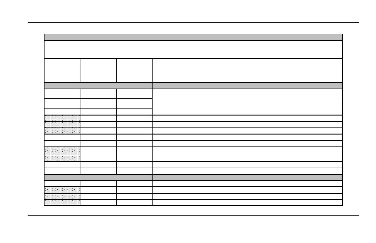
ZEITPLAN FÜR WARTUNGSINSPEKTIONEN
MODELLE fahrzeugbetriebene LKW-Geräte
Empfohlen A B
Alle 500 h Alle 1.500 h Alle 3.000 h
oder oder oder
6 Monate 12 Monate 24 Monate
Elektrik
5 5 5
Datenlogger herunterladen – Alarm nach Codes und Betrieb und Funktionsweise des Systems prüfen und
(sofern zutreffend) Abhilfemaßnahmen ergreifen.
5 5 5
Abtaueinleitung und -beendigung überprüfen. Betrieb der Verdampferventilatoren während des Abtaubetriebs
überprüfen (Ventilatoren sollten während des Abtaubetriebs stoppen).
5 5 5
Thermostatschaltsequenz überprüfen.
5 5
Sicherheitsvorrichtungen in den schließenden Kreisläufen prüfen.
5 5
Kalibrierung von Thermostat und Temperatursensor prüfen.
5 5
Auf lose Kabel oder Steckverbindungen prüfen.
5 5 5
Kabel und Kabelbäume auf Scheuerstellen prüfen.
5 5 5
Betrieb der Kondensator- und Verdampferventilatoren prüfen.
5 5
Kohlebürsten des Gleichstrommotors überprüfen. Vor 2.000 Stunden ersetzen. (Wenn bei der nächsten
Wartunginspektion 2.000 Stunden überschritten werden, Austausch bei dieser Inspektion durchführen.)
5 5 5
Betrieb alles externen Zubehörs von Thermo King prüfen.
5 5 5
Betrieb alles externen Zubehörs, das nicht von Thermo King stammt, prüfen.
Struktur
5 5 5
Sichtprüfung des Geräts auf beschädigte, lose oder defekte Teile durchführen.
5 5
Abtauabflüsse reinigen.
5 5
Verdampfer und Kondensator und die Wärmesenke am Brückengleichrichter reinigen.
5 5
Alle Befestigungsschrauben, Halterungen, Leitungen, Schläuche usw. prüfen.
Folgendes überprüfen/reparieren
Der Wartungstechniker ist während Wartungsarbeiten dafür verantwortlich, den Zustand aller vorhandenen Teile und Komponenten zu beurteilen.
Diese müssen sich in einem geeigneten Zustand befinden, sodass der problemlose Betrieb bis zur nächsten geplanten Wartung möglich ist. Wird
der Zustand der Teile nicht für geeignet befunden, müssen sie ersetzt werden.
53
Page 54

ZEITPLAN FÜR WARTUNGSINSPEKTIONEN
MODELLE fahrzeugbetriebene LKW-Geräte
Empfohlen A B
Alle 500 h Alle 1.500 h Alle 3.000 h
oder oder oder
6 Monate 12 Monate 24 Monate
Kältesystem
5 5 5
Sichtprüfung auf Lecks der Kältemittelschläuche, Rohre und Fittings durchführen.
5 5 5
Sichtprüfung auf Scheuerstellen der Kältemittelschläuche, Rohre und Fittings durchführen.
5 5 5
Verlegung der Kältemittelschläuche im Hauptkompressor überprüfen.
5 5 5
Kältemittelfüllmenge überprüfen.
5 5
Druckregelventile überprüfen.
5
Dehydrator austauschen.
5 5
Ölabscheider kontrollieren.
5
Filter in der Einlasssaugleitung des Kompressors beim Austausch des Trockners prüfen. (Oder falls das System
aus einem anderen Grund geöffnet wird.)
5 5 5
Betrieb der Kompressorkupplungen prüfen
5 5
Temperaturänderung während Heiz- und Kühlzyklen prüfen und sicherstellen. (Heizzyklus sofern vorhanden).
5 5
Gültigkeit der F-Gas-Zertifizierung gemäß örtlichen Bestimmungen prüfen. (Zertifizierung ist nicht in der
vorbeugenden Wartung enthalten).
Antriebskit (Kompressorhalter, siehe Wartungsempfehlungen des Herstellers).
5 5
Sichtprüfung des Kits für die Kompressorbefestigung und der dazugehörigen Komponenten durchführen.
5 5
Prüfen, dass alle Schrauben der Halterung festgezogen sind.
5 5
Überprüfen, ob unnormale Vibrationen vorhanden sind.
5
Riemen gemäß Empfehlungen des Herstellers austauschen.
5 5
Zustand und Spannung der Riemen gemäß Empfehlungen des Herstellers überprüfen.
Folgendes überprüfen/reparieren
54
Page 55

GARANTIE
GARANTIE
Wenn Sie während der Garantiezeit
Garantieleistungen oder Reparaturarbeiten in
Anspruch nehmen möchten, legen Sie einfach
Ihren Garantieschein bei einem der im
King-Kundendienstverzeichnis
Thermo
aufgeführten Händler vor. Dieser wird
gerne gemäß der nachstehenden
Ihnen
Garantiezusammenfassung behilflich sein.
GARANTIEZUSAMMENFASSUNG
Die vollständigen Bestimmungen der
eingeschränkten Garantie von Thermo King sind
bei Ihrem Thermo-King-Händler erhältlich.
Hinweis: Austausch oder Reparatur von
Geräteteilen im Rahmen der Garantie müssen
einem autorisierten Thermo-King-Händler
von
durchgeführt werden.
Hinweis: Änderungen von
Garantiebestimmungen und -zeiten bleiben
vorbehalten. Ihr Thermo-King-Händler kann
Ihnen die für Ihr jeweiliges Gerät geltende
Garantie nennen.
KÄLTEMITTELRÜCKGEWINNUNG
Wir von Thermo King erkennen die
Notwendigkeit, die Umwelt zu schützen und die
potenzielle Gefahr für die Ozonschicht
einzuschränken, die aus dem Entweichen von
Kältemittel in die Atmosphäre resultiert. Wir
verfolgen daher strikt eine Politik, die die
Rückgewinnung von Kältemitteln fördert und
das Entweichen von Kältemitteln in die
Atmosphäre einschränkt.
55
Page 56

GARANTIE
56
Page 57

Manual del operador de la serie Ce
TK 60980-ES-18-OP (Vers. 3, 04/16)
Page 58

ESPAÑOL ÍNDICE
Introducción. . . . . . . . . . . . . . . . . . . . . . . . . . . . . . . . . . . . . . . . . . . . . . . . . . . . . . . . . . . . . . . . . . . . . . . . . . . . . . . . . . 59
Funcionamiento general. . . . . . . . . . . . . . . . . . . . . . . . . . . . . . . . . . . . . . . . . . . . . . . . . . . . . . . . . . . . . . . . . . . . . . . . . . . .60
Precauciones de seguridad . . . . . . . . . . . . . . . . . . . . . . . . . . . . . . . . . . . . . . . . . . . . . . . . . . . . . . . . . . . . . . . . . . . . . 61
Refrigerante . . . . . . . . . . . . . . . . . . . . . . . . . . . . . . . . . . . . . . . . . . . . . . . . . . . . . . . . . . . . . . . . . . . . . . . . . . . . . . . . . . . . .61
Primeros auxilios: Refrigerante . . . . . . . . . . . . . . . . . . . . . . . . . . . . . . . . . . . . . . . . . . . . . . . . . . . . . . . . . . . . . . . . . . . . . .61
Aceite refrigerante . . . . . . . . . . . . . . . . . . . . . . . . . . . . . . . . . . . . . . . . . . . . . . . . . . . . . . . . . . . . . . . . . . . . . . . . . . . . . . . .61
Primeros auxilios: Aceite refrigerante. . . . . . . . . . . . . . . . . . . . . . . . . . . . . . . . . . . . . . . . . . . . . . . . . . . . . . . . . . . . . . . . . .62
Arranque automático . . . . . . . . . . . . . . . . . . . . . . . . . . . . . . . . . . . . . . . . . . . . . . . . . . . . . . . . . . . . . . . . . . . . . . . . . . . . . .62
Riesgos relacionados con el sistema eléctrico. . . . . . . . . . . . . . . . . . . . . . . . . . . . . . . . . . . . . . . . . . . . . . . . . . . . . . . . . . .62
Sistema de control electrónico . . . . . . . . . . . . . . . . . . . . . . . . . . . . . . . . . . . . . . . . . . . . . . . . . . . . . . . . . . . . . . . . . . 63
Descripción del sistema de control electrónico . . . . . . . . . . . . . . . . . . . . . . . . . . . . . . . . . . . . . . . . . . . . . . . . . . . . . . . . . .63
Controles de la unidad . . . . . . . . . . . . . . . . . . . . . . . . . . . . . . . . . . . . . . . . . . . . . . . . . . . . . . . . . . . . . . . . . . . . . . . . . . . . .64
Instrucciones de funcionamiento . . . . . . . . . . . . . . . . . . . . . . . . . . . . . . . . . . . . . . . . . . . . . . . . . . . . . . . . . . . . . . . . 65
Inspección semanal antes del viaje . . . . . . . . . . . . . . . . . . . . . . . . . . . . . . . . . . . . . . . . . . . . . . . . . . . . . . . . . . . . . . . . . . .65
Puesta en marcha de la unidad . . . . . . . . . . . . . . . . . . . . . . . . . . . . . . . . . . . . . . . . . . . . . . . . . . . . . . . . . . . . . . . . . . . . . .66
Pantalla estándar . . . . . . . . . . . . . . . . . . . . . . . . . . . . . . . . . . . . . . . . . . . . . . . . . . . . . . . . . . . . . . . . . . . . . . . . . . . . . . . . .66
Introducción de la temperatura del punto de consigna . . . . . . . . . . . . . . . . . . . . . . . . . . . . . . . . . . . . . . . . . . . . . . . . . . . .66
Inicio del ciclo de descarche manual del evaporador. . . . . . . . . . . . . . . . . . . . . . . . . . . . . . . . . . . . . . . . . . . . . . . . . . . . . .67
Alarmas . . . . . . . . . . . . . . . . . . . . . . . . . . . . . . . . . . . . . . . . . . . . . . . . . . . . . . . . . . . . . . . . . . . . . . . . . . . . . . . . . . . . . . . .67
Descripciones de los códigos de alarma . . . . . . . . . . . . . . . . . . . . . . . . . . . . . . . . . . . . . . . . . . . . . . . . . . . . . . . . . . . . . . .68
Borrado de los códigos de alarma . . . . . . . . . . . . . . . . . . . . . . . . . . . . . . . . . . . . . . . . . . . . . . . . . . . . . . . . . . . . . . . . . . . .68
Visualización de las pantallas de información . . . . . . . . . . . . . . . . . . . . . . . . . . . . . . . . . . . . . . . . . . . . . . . . . . . . . . . . . . .68
Inspección después del arranque . . . . . . . . . . . . . . . . . . . . . . . . . . . . . . . . . . . . . . . . . . . . . . . . . . . . . . . . . . . . . . . . . . . .69
Procedimiento de carga . . . . . . . . . . . . . . . . . . . . . . . . . . . . . . . . . . . . . . . . . . . . . . . . . . . . . . . . . . . . . . . . . . . . . . . . . . . .69
Procedimiento después de la carga. . . . . . . . . . . . . . . . . . . . . . . . . . . . . . . . . . . . . . . . . . . . . . . . . . . . . . . . . . . . . . . . . . .69
Revisiones semanales antes del viaje . . . . . . . . . . . . . . . . . . . . . . . . . . . . . . . . . . . . . . . . . . . . . . . . . . . . . . . . . . . . . . . . .69
Revisiones semanales después del viaje. . . . . . . . . . . . . . . . . . . . . . . . . . . . . . . . . . . . . . . . . . . . . . . . . . . . . . . . . . . . . . .69
Programa de inspección de mantenimiento. . . . . . . . . . . . . . . . . . . . . . . . . . . . . . . . . . . . . . . . . . . . . . . . . . . . . . . . 70
Garantía . . . . . . . . . . . . . . . . . . . . . . . . . . . . . . . . . . . . . . . . . . . . . . . . . . . . . . . . . . . . . . . . . . . . . . . . . . . . . . . . . . . . . 73
58
Page 59

INTRODUCCIÓN
THERMO ASSISTANCE
Thermo Assistance es una herramienta de
comunicación multilingüe diseñada para ponerle
en contacto directamente con un concesionario de
servicio autorizado en caso necesario.
Para emplear este sistema, necesitará conocer
siguiente información antes de efectuar
la
una llamada:
• El teléfono de contacto
• El tipo de unidad de TK
• El ajuste del termostato
• La temperatura de la carga actual
• La posible causa del fallo
• Si la unidad está en garantía
• Cómo pagará la reparación
Consulte el Directorio de servicios de Thermo
King.
Facilite su nombre y número de teléfono de
contacto al operador de Thermo Assistance y
solicite que le devuelva la llamada.
Assistance le devolverá la llamada y
Thermo
usted podrá proporcionar los detalles relativos al
servicio que necesite para que pueda organizarse
la reparación.
Tenga en c uenta que Thermo Assistance no puede
garantizar pagos y que el servicio está diseñado
exclusivamente para vehículos de transporte
refrigerado equipados con productos fabricados
por Thermo King Corporation.
RENUNCIA DE RESPONSABILIDAD
El fabricante, Thermo King Corporation, no será
responsable de ningún acto o acción llevados a
cabo por el propietario u operador durante la
reparación o el funcionamiento de los productos
descritos en el presente manual que resulten
contrarios a las instrucciones impresas del
fabricante. No existen garantías implícitas o
explícitas, incluyendo garantías que resulten de
la venta, uso o comercialización, con respecto a
la información, recomendaciones y descripción
contenidas en el presente documento.
fabricante no es responsable ni podrá
El
considerársele responsable, por contrato ni por
medios extracontractuales (incluida negligencia)
de ningún daño especial, indirecto o derivado,
como perjuicios o daños provocados a vehículos,
contenidos o personas como consecuencia de la
instalación de cualquier producto de
King, su fallo mecánico o la no
Thermo
observación por parte del propietario u operador
de los adhesivos de precaución y seguridad que
se encuentran colocados en posiciones
estratégicas en el
producto.
INTRODUCCIÓN
Thermo King Spain ha desarrollado un nuevo
mando de control digital con un microprocesador
programable que controla el funcionamiento de la
unidad y muestra esta información en la pantalla
de forma clara y rápida.
Estos nuevos mandos de control en cabina se han
diseñado para usarse en las unidades de la serie eC
de Thermo King.
Si bien no le resultará difícil aprender a utilizar
mandos de control en cabina fabricados por
los
Thermo King Spain, le será de gran utilidad
dedicar unos minutos a examinar el contenido
este manual.
de
Los mandos de control en cabina pueden
funcionar con unidades de 12 y 24
Es posible mostrar las temperaturas en grados
centígrados o Fahrenheit.
El presente manual del conductor se publica solo
para efectos de información general, y no debe
considerarse exhaustivo ni destinado a cubrir
todas las eventualidades. En caso de precisar más
información, no dude en consultar su Directorio
de servicios de Thermo
emplazamiento y el número de teléfono del
concesionario local.
Todos los requisitos de mantenimiento, ya sean
mayores o menores, deben ser atendidos por un
concesionario de Thermo King debido a cuatro
motivos muy importantes:
1. Los concesionarios cuentan con las
herramientas recomendadas por la fábrica para
realizar todas las funciones de mantenimiento.
2. Cuentan con técnicos formados y autorizados
por la fábrica.
King para conocer el
V.
59
Page 60

INTRODUCCIÓN
Descenso de
la temperatura
Punto de consigna
de la temperatura
Aumento de la
temperatura
X°C/F por encima del
punto de consigna
X°C/F por debajo del
punto de consigna
REFRIGERACIÓN
CALEFACCIÓN
MODO DE
TIEMPO
VACÍO
3. Cuentan con piezas de repuesto originales de
Thermo King.
4. La garantía de su nueva unidad es válida cuando un
concesionario autorizado de Thermo King efectúa
la reparación y/o la
sustitución de las piezas.
Si realiza regularmente comprobaciones antes de cada
viaje, minimizará los problemas de funcionamiento
“en carretera”. Seguir atentamente un programa de
mantenimiento también le ayudará a conservar su
unidad en las mejores condiciones de funcionamiento.
Si se siguen los procedimientos recomendados de
fábrica, sabrá que ha adquirido el sistema de control de
temperatura más seguro y eficiente disponible en el
mercado.
FUNCIONAMIENTO GENERAL
En las unidades accionadas por camión, el control de
temperatura está basado en dos valores:
configuración
electrónico y la temperatura de retorno del evaporador.
La diferencia entre estas dos temperaturas determinará
el modo de funcionamiento: refrigeración, calefacción
o tiempo vacío.
•
Refrigeración:
compartimento de carga es mayor a la del punto de
consigna, la unidad funciona en modo de
refrigeración para reducir la temperatura de retorno
del evaporador.
60
(punto de consigna)
Cuando la temperatura en el
la
del termostato
•
Calefacción:
Cuando la temperatura del
compartimento de carga es inferior a la del punto de
consigna, la unidad cambia al modo de calefacción
para aumentar la temperatura del aire de retorno del
evaporador.
•
Tiempo vacío:
Una vez que se haya alcanzado la
temperatura del punto de consigna y mientras que la
temperatura permanezca entre los X°C/F por
encima o por debajo del punto de consigna, no
existirá ninguna demanda de transferencia de calor
o frío y la unidad permanecerá en modo de tiempo
vacío.
•
Descarche:
en modo de refrigeración (entre 30
horas), la unidad permanecerá en el cuarto modo
8
Tras un periodo programado de tiempo
minutos y
de operación para eliminar el hielo que se acumule
en los serpentines del condensador y del
evaporador. El descarche puede iniciarse manual
automáticamente.
o
El ajuste de fábrica para X es de 3°C (5°F). Durante la
instalación de la unidad, se puede ajustar este valor en
aumentos de 1ºC/F .
Unidades con refrigerante R-134a sin
descarche: Las temperaturas se pueden controlar
de 0ºC a +22ºC (+32ºF a +71ºF).
Unidades con refrigerante R-134a con
descarche: Las temperaturas se pueden controlar
de -10ºC a +22ºC (+14ºF a +71ºF).
Unidades equipadas con el refrigerante R-404A:
Las temperaturas se pueden controlar de -32ºC a
+22ºC (de -26°F a +71°F).
Dirección:
Sant Josep, 140-142 P.I.
Pla”, Sant Feliu de
“El
Llobregat, Barcelona, España.
Año de fabricación: Consulte la placa con
número de serie.
el
La instalación y puesta en servicio es realizada
por un concesionario autorizado de Thermo King,
según los procedimientos y los planos de
King. Solo se permiten excepciones
Thermo
la autorización escrita del fabricante.
con
Page 61

PRECAUCIONES DE SEGURIDAD
PRECAUCIONES
DE
SEGURIDAD
¡ADVERTENCIA!
Esta unidad no se ha diseñado para su uso por
parte de personas (incluidos niños) con
discapacidades mentales, sensoriales o físicas o de
personas sin los conocimientos o la experiencia
adecuados, salvo que hayan estado bajo
supervisión o hayan recibido instrucciones sobre la
utilización de la unidad por parte de una person a
responsable de su seguridad.
Debe impedirse que los niños jueguen con
la unidad.
Thermo King recomienda que todas las tareas de
reparación y mantenimiento se lleven a cabo en un
concesionario de Thermo King. Sin embargo, existen
varias prácticas de seguridad generales que usted
debería conocer:
1. Cuando esté trabajando con el sistema de
refrigeración o cerca de él, utilice siempre gafas
protectoras o de seguridad. Si el refrigerante o el
ácido de la batería entran en contacto con los ojos,
pueden provocar daños irreversibles.
2. No ponga nunca en funcionamiento la unidad con
la válvula de descarga del compresor cerrada.
3. Mantenga en todo momento las manos y la ropa
holgada lejos de los ventiladores y las correas
cuando la unidad esté funcionando o cuando esté
abriendo o cerrando las válvulas de servicio
compresor .
del
4. Si por cualquier razón necesita perforar orificios en
la unidad, adopte las máximas precauciones, ya que
podría debilitar componentes estructurales. Si se
taladran el cableado eléctrico o los tubos de
refrigerante, podría provocarse un incendio.
5. Se recomienda confiar a un técnico autorizado de
Thermo King cualquier labor de mantenimiento
que deba efectuarse en los serpentines del
evaporador o del condensador. No obstante, si
tuviera que trabajar cerca de los serpentines, tome
las máximas precauciones, ya que las aletas
expuestas del serpentín pueden ocasionar heridas
dolorosas.
REFRIGERANTE
A pesar de que los refrigerantes con fluorocarbono
están clasificados como seguros, tome precauciones
cuando trabaje con refrigerantes o cerca de las áreas
donde estos se estén utilizando durante las operaciones
de mantenimiento de su unidad.
Si se liberan a la atmósfera accidentalmente, los
refrigerantes con fluorocarbono en estado líquido se
evaporan con gran rapidez y congelan cualquier objeto
con el que entran en contacto.
Los refrigerantes con fluorocarbono utilizados en las
unidades de aire acondicionado pueden producir gases
tóxicos que, en presencia de una llama o un
cortocircuito, irritan gravemente las vías respiratorias,
pudiendo provocar la muerte.
PRIMEROS AUXILIOS: REFRIGERANTE
OJOS:
Si el líquido entra en contacto con los ojos,
lávelos inmediatamente con agua abundante y obtenga
atención médica urgentemente.
PIEL:
Lave la zona afectada con abundante agua tibia
y manténgala fría. Cubra las quemaduras con vendajes
secos, estériles y gruesos para impedir infecciones o
heridas. Obtenga atención médica.
INHALACIÓN:
Lleve a la víctima a un lugar bien
ventilado y restablezca la respiración en caso
necesario. Permanezca con la víctima hasta que llegue
el personal médico de urgencia.
ACEITE REFRIGERANTE
Tenga siempre en cuenta las siguientes
precauciones al trabajar con aceite refrigerante:
OJOS: Procure que el aceite refrigerante no entre
en contacto con los ojos.
PIEL: Evite el contacto prolongado o reiterado
con la piel o la ropa.
IRRITACIÓN: Para prevenir irritaciones, lávese
bien inmediatamente después de la manipulación.
61
Page 62

PRECAUCIONES DE SEGURIDAD
PRIMEROS AUXILIOS: ACEITE REFRIGERANTE
OJOS: Lave los ojos inmediatamente con
abundante agua durante al menos 15 minutos
manteniendo los párpados abiertos. Obtenga
atención médica urgentemente.
PIEL: Retire la ropa contaminada. Lave con
abundante agua y jabón. Obtenga atención médica
en caso de que la irritación persista.
INHALACIÓN: Lleve a la víctima a un lugar bien
ventilado y restablezca la respiración en caso
necesario. Permanezca con la víctima hasta que
llegue el personal médico de urgencia.
INGESTIÓN: No provoque el vómito. Llame
inmediatamente al Servicio Médico de
Información Toxicológica local o a un médico.
Los refrigerantes con fluorocarbono tienden a
desplazar el aire, lo cual puede causar la reducción
de oxígeno y, en consecuencia, estados de
inconsciencia o muerte por asfixia. Tome
precauciones en todo momento cuando esté
trabajando con o cerca de los refrigerantes o de
sistemas de aire acondicionado que contengan
refrigerantes, especialmente en áreas cerradas
restringidas.
o
ARRANQUE AUTOMÁTICO
Las unidades de refrigeración impulsadas por
camión de Thermo King pueden arrancar
automáticamente en cualquier momento.
Asegúrese de que la unidad esté desconectada
antes de inspeccionar cualquier componente.
RIESGOS RELACIONADOS CON
SISTEMA ELÉCTRICO
EL
Asegúrese de que el suministro de energía
eléctrica de alto voltaje se encuentra apagado y
desconecte el cable eléctrico antes de trabajar en
la unidad. Las unidades con un suministro de
energía eléctrica representan un posible peligro
eléctrico.
La soldadura eléctrica genera corrientes de alto
amperaje que pueden dañar los componen tes
eléctricos y electrónicos. Para reducir los daños,
antes de cualquier operación de soldadura en el
vehículo, deberán desconectarse eléctricame nte
el controlador del microprocesador y la batería de
la unidad del vehículo. Apague el interruptor de
encendido/apagado del microprocesador . Extraiga
el cable negativo de la batería. Extraiga todos los
conectores de la parte posterior del controlador
por microprocesador . Cierre el mando de control.
Conecte el cable soldador a tierra lo más cerca
posible de la zona donde se esté realizando la
soldadura. Cuando haya finalizado la soldadura,
retire el cable soldador a tierra. Vuelva a conectar
los cables a la parte posterior del controlador por
microprocesador. V uelva a con ectar el cable
negativo de la batería. Encienda el interruptor de
encendido/apagado del microprocesado r.
Reajuste todas las alarmas y códigos a los ajustes
anteriores. Realice una inspección antes del viaje
completa. Encontrará las instrucciones d etalladas
en el Procedimiento de mantenimiento A26A
de Thermo King.
ADVERTENCIA
62
Page 63

SISTEMA DE CONTROL ELECTRÓNICO
Las unidades de refrigeración de transmisión
directa de Thermo King están compuestas por una
unidad de condensador, una unidad del
evaporador, un compresor del vehículo y un panel
de control (mando de control en cabina) que opera
la unidad.
El sistema de control electrónico está formado por
un módulo de control electrónico (ubicado en el
interior del condensador) y el mando de control en
cabina. Este mando de control en cabina permite
al conductor del camión utilizar la unidad de
refrigeración de Thermo King.
Mando de control en cabina
DESCRIPCIÓN DEL SISTEMA
CONTROL ELECTRÓNICO
DE
El sistema de control electrónico cuenta con
siguientes características:
las
• Arranque automático
• Arranque retardado
• Pantalla activa
• Alarma de bajo voltaje de la batería
• Pantalla del valor del voltaje de la batería
• Unidad de control sin mando de control
cabina
en
• Descarche manual o automático
• Sensor de la temperatura del aire de retorno
• Lectura de la temperatura del punto de
consigna
Arranque automático: En caso de un corte de
energía, si la unidad estaba encendida, la unidad
volverá a accionarse cuando se restablezca la
energía.
Arranque retardado: Tras un arranque
automático, la unidad permanecerá inactiva
durante algunos segundos.
Pantalla activa: La pantalla del mando de control
en cabina se encuentra siempre activa, excepto
cuando la unidad está desconectada (sin
alimentación) o cuando está conectada, pero se ha
apagado manualmente desde el mando de control
en cabina (cuando no hay una alarma activa).
Contador horario del total de horas: Número
total de horas que la unidad está en
funcionamiento.
SISTEMA DE CONTROL ELECTRÓNICO
Contador horario del compresor del vehículo:
Número de horas que la unidad ha estado
funcionando en carretera.
Alarma de bajo voltaje de la batería: Desconecta
la unidad cuando el voltaje de la batería es
demasiado bajo.
Pantalla del valor del voltaje de la batería:
Se muestra el valor del voltaje de la batería en
el menú de información.
Unidad de control sin mando de control en
cabina: El sistema de control eléctrico sin el
mando de control en cabina también puede
gestionar la unidad bajo las condiciones
seleccionadas por el mando de control en cabina
antes de su desconexión.
Descarche manual o automático: Es posible
elegir entre el descarche manual o automático y
seleccionar el intervalo de tiempo de descarche en
el modo de descarche automático.
Sensor de la temperatura del aire de retorno:
Lectura en pantalla de la temperatura del
compartimento de carga.
Lectura de la temperatura del punto de
consigna: Lectura en pantalla de la temperatura
del punto de consigna.
63
Page 64

SISTEMA DE CONTROL ELECTRÓNICO
CONTROLES DE LA UNIDAD
ADVERTENCIA
No utilice nunca la unidad salvo que haya
comprendido por completo el funcionamiento
de los controles; de lo contrario, puede sufrir
una lesión grave.
MANDO DE CONTROL EN CABINA
Pantalla, teclas y símbolos
1. Pantalla: Se encuentra siempre activa, excepto
cuando la unidad está desconectada (sin
alimentación) o cuando está conectada pero se ha
apagado manualmente desde el mando de control
en cabina. Normalmente, muestra la temperatura
del aire de retorno.
2. Tecla de ENCENDIDO/APAGADO: Esta tecla se
utiliza para poner en marcha/detener la unidad
pulsándola durante, al menos, 1 segundo.
pulsarla una sola vez, permite retroceder
Al
menú del nivel anterior.
al
3. Tecla SET de ajuste: Selecciona las pantallas
indicadoras y las de información. Al pulsarla una
sola vez, se accede al menú del siguiente nivel.
4. Tecla de dirección hacia arriba: Se utiliza para
incrementar la temperatura del punto de consigna
y los valores de la pantalla, así como para
desplazarse hacia arriba en los menús.
5. Tecla de dirección hacia abajo: Se utiliza para
reducir la temperatura del punto de consigna y los
valores de la pantalla, así como para desplazarse
hacia abajo en los menús.
6. Símbolo de refrigeración: La unidad se
encuentra en modo de refrigeración.
7. Símbolo de calefacción: La unidad se
encuentra en modo de calefacción.
8. Pantalla de ºC/ºF: Indica si la lectura de la
temperatura en pantalla se ofrece en grados
centígrados (°C) o Fahrenheit (°F).
9. Símbolo de alarma: Indica que existe una
alarma en el sistema.
10. Símbolo de descarche: Indica que el
evaporador se encuentra en modo de descarche.
11. Símbolo del punto (decimal): Indica la
presencia de alimentación, solo cuando la unidad
está apagada.
64
Page 65

INSTRUCCIONES DE FUNCIONAMIENTO
Asegúrese de realizar las siguientes inspecciones
antes del viaje antes de poner en marcha la unidad.
INSPECCIÓN SEMANAL ANTES
VIAJE
DEL
Debe realizarse la siguiente inspección semanal
antes del viaje antes de cargar el camión.
inspección semanal no sustituye a las
La
inspecciones de mantenimiento regulares
(consulte la sección relativa al programa de
inspección de mantenimiento). No obstante, se
trata de una parte importante del programa de
mantenimiento preventivo que se ha diseñado
para evitar problemas de funcionamiento antes
que se produzcan.
de
1. Fugas: Compruebe si existen fugas de
refrigerante y tubos de refrigerante desgastados.
2. Batería: Los terminales deben estar apretados
correctamente y no mostrar signos de corrosión.
3. Correas: Compruebe si existen grietas o
desgaste y si la tensión de las correas es la
adecuada.
4. Soporte de montaje: Asegúrese de que los
tornillos están totalmente apretados.
5. Sistema eléctrico: Las conexiones eléctricas
deben estar bien fijadas. Los cables y los
terminales no deben presentar signos de corrosión,
grietas ni humedad.
6. Estructura: Revise visualmente si existe algún
daño físico.
7. Serpentines: Los serpentines del condensador
y del evaporador deben estar limpios y no
presentar residuos.
Debería bastar con utilizar agua limpia para su
limpieza. Se desaconseja firmemente la
utilización de limpiadores o detergentes debido a
la posibilidad de que deterioren la estructura. Si se
utiliza un aparato de limpieza de alta presión, la
presión de la boquilla no debería superar 41 bar
(600 psi). Para garantizar los mejores resultados,
pulverice el serpentín en perpendicular con
respecto a su parte delantera. La boquilla de
pulverización debería mantenerse a entre 25 y
mm (entre 1 y 3 pulgadas) de la superficie
75
del serpentín.
Si es necesario utilizar un detergente o un
limpiador químico, utilice uno que no contenga
ácido fluorhídrico y que tenga un pH de entre 7
8. Asegúrese de que se siguen las instrucciones
y
de dilución proporcionadas por el proveedor del
detergente. En caso de duda con respecto a la
compatibilidad del detergente con el tipo de
materiales enumerados anteriormente, pida
siempre al proveedor una confirmación por escrito
de dicha compatibilidad. En caso de que sea
necesario utilizar un limpiador químico, es
OBLIGATORIO aclarar por completo todos los
componentes con agua, incluso si en las
INSTRUCCIONES DE FUNCIONAMIENTO
instrucciones se indica que se trata de un
limpiador que no requiere aclarado. De no
cumplirse las directrices anteriores, la vida útil del
equipo se verá reducida de forma indeterminable.
El transporte reiterado de desechos de carne y
pescado puede provocar una gran corrosión en los
serpentines del evaporador y en los tubos de la
sección del evaporador con el paso del tiempo
debido a la formación de amoníaco, lo cual puede
reducir la vida útil de los serpentines. Deben
adoptarse las medidas adicionales adecuadas para
proteger los serpentines de la corrosión agresiva
que puede derivarse del transporte de dichos
productos.
8. Compartimento de carga: Compruebe que no
haya ningún daño ni en el interior ni en el exterior
del camión. Cualquier daño en las paredes o el
aislamiento deberá repararse.
9. Drenajes de descarche: Compruebe las
mangueras de drenaje de descarche y sus
conexiones para asegurarse de que no están
obstruidas.
10. Puertas: Asegúrese de que las puertas y los
sellos contra la intemperie están en buenas
condiciones y cierran herméticamente.
11. Visor: Verifique que el visor de la carga de
refrigerante en la unidad en funcionamiento esté
completamente lleno (la temperatura del
compartimento de carga debe ser de
aproximadamente 0ºC).
65
Page 66

INSTRUCCIONES DE FUNCIONAMIENTO
PUESTA EN MARCHA DE LA UNIDAD
Funcionamiento por motor
1. Ponga en marcha el motor del camión.
El símbolo del punto permanecerá encendido.
2. Pulse el interruptor de ENCENDIDO/
APAGADO ubicado en el mando de control
cabina durante, al menos, 1 segundo.
en
activará la pantalla del mando de control
Se
en cabina.
3. Compruebe el punto de consigna y ajústelo,
ser necesario.
de
Nota: Se recomienda realizar una supervisión
regular de la unidad; la frecuencia de esta
supervisión dependerá del tipo de carga.
PANTALLA ESTÁNDAR
Esta es la pantalla que aparece cuando se presiona
la tecla de ENCENDIDO/APAGADO durante
segundo y la unidad se pone en marcha.
1
Normalmente, muestra la temperatura del aire de
retorno y el modo de funcionamiento actual con
símbolo adecuado.
el
Si hay una alarma, el símbolo de alarma también
aparecerá en la pantalla.
El ejemplo de la ilustración muestra el modo de
refrigeración con una temperatura de 10°C.
INTRODUCCIÓN DE LA
TEMPERATURA DEL PUNTO
CONSIGNA
DE
La temperatura del punto de consigna puede
modificarse de forma rápida y sencilla.
1. Pulse y suelte la tecla SET de ajuste una vez
aparecerán las letras SP en la pantalla.
y
2. Vuelva a pulsar la tecla SET de ajuste y
aparecerá la temperatura actual del punto de
consigna en la pantalla.
66
Page 67

INSTRUCCIONES DE FUNCIONAMIENTO
3. Pulse las teclas de dirección hacia ARRIBA o
hacia ABAJO para seleccionar la temperatura
del punto de consigna deseada. Cada vez que
pulse y suelte alguna de estas teclas, la
temperatura del punto de consigna cambiará
grado. La temperatura del punto de consigna
1
también cambiará continuamente si mantiene
pulsada la tecla de dirección hacia ARRIBA o
hacia ABAJO sin soltarla.
4. Pulse y suelte la tecla SET de ajuste para
configurar el punto de consigna.
5. Pulse y suelte la tecla de ENCENDIDO/
APAGADO dos veces para regresar a la
pantalla estándar.
¡PRECAUCIÓN!
Si la tecla SET de ajuste no se pulsa en un
intervalo de 20 segundos para seleccio nar la
nueva temperatura del punto de consigna, la
unidad seguirá funcionando con la temperatura
del punto de consigna original.
INICIO DEL CICLO DE DESCARCHE MANUAL DEL EVAPORADOR
¡PRECAUCIÓN!
Antes de iniciar un descarche manual,
asegúrese de que la unidad no se encuentra ya
en un ciclo de descarche. Cuando la unidad
esté en un ciclo de descarche, el símbolo de
descarche aparecerá en la pantalla.
1. Pulse y suelte la tecla SET de ajuste una vez y,
a continuación, pulse las teclas de dirección
hacia ARRIBA o hacia ABAJO y se mostrarán
las letras dEF en pantalla.
2. Para activar el descarche manual, pulse la tecla
SET de ajuste durante 3 segundos.
3. Pulse la tecla de ENCENDIDO/APAGADO
una vez para regresar a la PANTALLA
ESTÁNDAR, donde aparecerá el símbolo de
DESCARCHE cuando se inicie el ciclo de
descarche (la temperatura del compartimento
de carga debe ser inferior a 3°C).
Nota: Para desactivar manualmente el
descarche, repita la misma operación.
ALARMAS
Cuando la unidad no está funcionando
correctamente, el microprocesador registra el
código de alarma, alerta al operador mostrando el
símbolo de ALARMA y, dependiendo del tipo de
alarma, apaga la unidad.
Existen dos categorías de alarma:
Arranque manual:
Si la alarma detiene la unidad, los símbolos del
punto y de ALARMA aparecen en la pantalla.
Una vez que haya corregido la condición de
alarma, debe pulsar la tecla de ENCENDIDO/
APAGADO para volver a poner en marcha
unidad.
la
Pulse y suelte la tecla SET de ajuste dos veces
para que se muestre el código de alarma actual en
la pantalla. Si hay más de una alarma activa, se
pueden visualizar todos los códigos de alarma de
la unidad secuencialmente pulsando y soltando la
tecla SET de ajuste y las teclas de las FLECHAS.
67
Page 68

INSTRUCCIONES DE FUNCIONAMIENTO
Arranque automático:
La alarma detiene la unidad, el símbolo de
ALARMA aparece en la pantalla y la unidad se
pone en marcha automáticamente una vez que se
haya corregido la condición de alarma.
Si se genera una alarma P1E (aparece el código de
alarma de error de la lectura de temperatura del
aire de retorno), --- aparecerá en la pantalla junto
con el símbolo de alarma, en lugar de la lectura de
la temperatura del aire de retorno.
68
Pulse y suelte la tecla SET de ajuste dos veces
para que se muestre el código de alarma actual en
la pantalla. Si hay más de una alarma activa, se
pueden visualizar todos los códigos de alarma de
la unidad secuencialmente pulsando y soltando la
tecla SET de ajuste y las teclas de las FLECHAS.
DESCRIPCIONES DE LOS CÓDIGOS DE ALARMA
Arranque manual
bAt Voltaje bajo de la batería.
Arranque automático
P1E Error de lectura de la temperatura del
E7 Fallo de las comunicaciones (no es
protección de la unidad y de la batería.
aire de retorno del compartimento de
carga (circuito abierto o con un
cortocircuito).
su concesionario de servicio.
posible leer ningún valor en el mando
de control en cabina, pero la unidad
sigue funcionando con el comando de
funcionamiento anterior).
contacto con su concesionario de
servicio.
Póngase en contacto con
Sistema de
Póngase en
BORRADO DE LOS CÓDIGOS
ALARMA
DE
En primer lugar, debe borrarse la condición de alarma
en la unidad. Tras borrar la condición de alarma, pulse
y suelte la tecla SET de ajuste para eliminar los
códigos de ALARMA existentes. Aparecerá la
pantalla estándar una vez que se hayan borrado los
códigos de ALARMA.
VISUALIZACIÓN DE LAS PANTALLAS DE INFORMACIÓN
MENÚ PRINCIPAL
En la
pantalla estándar
para abrir el
las teclas de las FLECHAS para que se muestren:
1. Las alarmas (si hay alguna activa)
2. El punto de consigna de la temperatura
3. El descarche manual del evaporador
Pulse la tecla de ENCENDIDO/APAGADO una vez
para regresar a la pantalla estándar.
MENÚ DE INFORMACIÓN
En la
hacia arriba durante 1 segundo para abrir el
información
ajuste para que se muestren:
1. tSt:
activados).
2. reL:
3. bAt:
4. toH:
permanecido encendida protegiendo la carga.
5. coH:
accionado por el motor.
menú principal
pantalla estándar
y, a continuación, utilice la tecla SET de
Prueba de la pantalla (todos los iconos
Versión del software.
Voltaje actual de la batería .
La cantidad total de tiempo que la unidad ha
Horas de funcionamiento del compresor
, pulse la tecla SET de ajuste
y, a continuación, utilice
, pulse la tecla de dirección
menú de
Page 69

INSTRUCCIONES DE FUNCIONAMIENTO
Regrese al menú principal pulsando la tecla de
ENCENDIDO/APAGADO.
Nota:
Cada contador horario se mostrará en horas
cuando el valor calculado sea < 1.000.
Cuando el valor sea >= 1.000, el número de horas se
mostrará alternat ivamente en tre horas y mi les, en las
carpetas “toh” o “coh”.
Por ejemplo, si el valor calculado es 12.055, “055” se
mostrará alternativamente con “12”, donde el
número de 3 dígitos corresponde siempre al número
de “horas”, mientras que el número de 2 dígitos
corresponde siempre al número de “miles de horas”.
INSPECCIÓN DESPUÉS
ARRANQUE
DEL
Termostato:
por encima y por debajo de la temperatura del
compartimento para revisar el funcionamiento del
termostato (ver los modos de
Preenfriamiento:
temperatura deseada, ponga en funcionamiento la
unidad durante media o una hora (o más tiempo, de ser
posible) antes de cargar el camión. El
elimina el calor residual y actúa como una buena
prueba del sistema de refrigeración.
Descarche:
preenfriar el interior del camión, la temperatura del
evaporador debería haber descendido por debajo de
2°C (35,6°F); inicie un ciclo de descarche manual con
el interruptor de descarche manual. El ciclo de
descarche debería finalizar de manera automática.
Ajuste la configuración del termostato
funcionamiento).
Con el termostato ajustado a la
preenfriamiento
Cuando la unidad haya terminado de
PROCEDIMIENTO DE CARGA
1. Para minimizar la acumulación de escarcha en el
serpentín del evaporador y el aumento de calor en el
interior del compartimento de carga, asegúrese de
que la unidad está APAGADA antes de abrir las
puertas. (La unidad puede seguir en funcionamiento
cuando se cargue el camión en un almacén con las
puertas cerradas).
2. Compruebe cuidadosamente y registre la
temperatura de la carga al cargar el camión.
Observe si algún producto se encuentra fuera del
rango de temperatura.
3. Cargue la mercancía manteniendo el espacio
suficiente para que el aire circule a través de la
carga. NO bloquee la entrada ni la salida del
evaporador.
4. Los productos deberían preenfriarse antes de
cargarse. Las unidades de Thermo King se han
diseñado para mantener la carga a la misma
temperatura a la que esta se ha cargado. Las
unidades de refrigeración para el transporte no se
han diseñado para reducir la temperatura de
carga.
la
PROCEDIMIENTO DESPUÉS
LA CARGA
DE
1. Asegúrese de que todas las puertas estén
cerradas y selladas.
2. Ajuste el termostato al punto de consigna de
temperatura deseada.
la
3. Ponga en marcha la unidad.
4. Media hora después de cargar el camión,
realice el descarche de la unidad durante un
momento pulsando el interruptor de descarche
manual. Si la temperatura del serpentín
desciende por debajo de 2°C (35,6°F), la
unidad iniciará el descarche. El ciclo de
descarche debería finalizar de manera
automática.
REVISIONES SEMANALES ANTES DEL VIAJE
1. Inspeccione visualmente las correas.
2. Observe si se producen ruidos anómalos,
vibraciones, etc.
3. Compruebe visualmente que no existen
pérdidas de fluido en la unidad (líquido
refrigerante, aceite, refrigerante, etc.).
4. Compruebe visualmente que no existen piezas
dañadas, sueltas o rotas en la unidad (incluidos
los conductos de aire y los tabiques divisores,
en caso de que formen parte del equipamiento
de la unidad).
5. En caso de que exista un exceso de suciedad o
una obstrucción, limpie la unidad, incluidos los
serpentines del evaporador y del condensador.
REVISIONES SEMANALES DESPUÉS DEL VIAJE
1. Limpie la cubierta exterior de la unidad. Utilice
un paño húmedo y detergentes neutros.
utilice disolventes ni productos de limpieza
No
fuertes.
2. Compruebe si hay fugas.
3. Compruebe que no haya tornillería suelta o que
se haya perdido.
4. Compruebe que la unidad no haya sufrido
daños físicos.
¡PRECAUCIÓN!
No utilice agua a presión.
69
Page 70

PROGRAMA DE INSPECCIÓN DE MANTENIMIENTO
MODELOS DE UNIDAD: Gama de unidades accionadas por el motor del vehículo
Inspección recomendada tras la primera semana
TRAS LA PRIMERA SEMANA de funcionamiento:
• Comprobar la tensión de las correas.
• Ajustar los pernos de montaje del soporte de montaje y de la unidad.
• Comprobar todas las mangueras y el cableado en busca de desgaste.
• Comprobar si existen fugas en las conexiones, los tubos y las mangueras de refrigerante.
Recomendado A B
Cada 500 horas
Cada
1.500 horas
Cada
3.000 horas
OO O
6 meses 12 meses 24 meses
Varios
stos procedimientos se pueden llevar a cabo como tareas adicionales a los procedimientos de
servicio estándar.
5
5
* Comprobar la calibración de los sensores del aire de retorno y de descarga anualmente o según el HACCP
del cliente. Comprobar también los registradores independientes, si se encuentran instalados. La prueba no
se incluye como parte del tiempo destinado al mantenimiento.
5
5 5
Comprobar el funcionamiento de todos los accesorios
.
5 5 5
Comprobar los registros de mantenimiento y verificar que se han llevado a cabo todas las modificaciones de
garantía y mantenimiento. (Actualizaciones no incluidas).
Inspeccionar/reparar los siguientes elementos
PROGRAMA DE INSPECCIÓN DE MANTENIMIENTO
Seguir debidamente un programa de mantenimiento también le ayudará a conservar su unidad de Thermo King en las mejores condiciones de funcionamiento.
El siguiente programa general se ofrece para ayudarle a realizar la comprobación del mantenimiento. Las tareas de mantenimiento deberían realizarse
cuando corresponda en función del modelo.
E
70
Page 71

PROGRAMA DE INSPECCIÓN DE MANTENIMIENTO
MODELOS DE UNIDAD: Gama de unidades accionadas por el motor del vehículo
Recomendado A B
Cada 500 horas
Cada
1.500 horas
Cada
3.000 horas
OO O
6 meses 12 meses 24 meses
Sistema eléctrico
5
5 5
Descargar el registrador de datos: Comprobar si se ha generado algún código de alarma, así como las
funciones y el funcionamiento del sistema, y tomar las acciones correctivas necesarias (cuando sea aplicable).
5
5 5
Comprobar el inicio y la finalización del descarche. Comprobar el funcionamiento de los ventiladores del
evaporador durante el descarche (los ventiladores deberían detenerse durante el descarche).
5
5 5
Comprobar la secuencia del interruptor del termostato.
5
5
Comprobar los dispositivos de seguridad de los circuitos de cierre.
5
5
Comprobar la calibración del sensor de temperatura y del termostato.
5
5
Comprobar la existencia de conexiones de los enchufes o cables sueltos.
5
5 5
Comprobar si los cables presentan desgaste por rozamiento.
5
5 5
Comprobar el funcionamiento de los ventiladores del evaporador y del condensador.
5
5
Inspeccionar las escobillas del motor de CC. Sustituirlas antes de 2.000 horas (si la siguiente inspección de
mantenimiento va a superar las 2.000 horas, será necesario cambiarlas en esta inspección).
5
5 5
Comprobar el funcionamiento de todos los equipos accesorios externos de Thermo King.
5
5 5
Comprobar el funcionamiento de todos los equipos accesorios externos no pertenecientes
a Thermo King.
Estructura
5
5 5
Inspeccionar visualmente la unidad para detectar piezas dañadas, sueltas o rotas.
5
5
Limpiar los drenajes de descarche.
5
5
Limpiar los serpentines del condensador y del evaporador y el absorbente de calor del rectificador puente.
5
5
Comprobar todos los pernos de montaje, soportes, tubos, mangueras, etc.
Inspeccionar/reparar los siguientes elementos
El técnico de mantenimiento es responsable de evaluar que el estado en el que se encuentran todas las piezas y componentes revisados,
durante cualquier operación de mantenimiento, es adecuado para que la unidad siga funcionando hasta el próximo mantenimiento programado.
Si se considera que las piezas no se encuentran en el estado adecuado, deberían sustituirse.
71
Page 72

PROGRAMA DE INSPECCIÓN DE MANTENIMIENTO
MODELOS DE UNIDAD: Gama de unidades accionadas por el motor del vehículo
Recomendado A B
Cada 500 horas
Cada
1.500 horas
Cada
3.000 horas
OO O
6 meses 12 meses 24 meses
Sistema de refrigeración
5
5 5
Inspeccionar visualmente si existen fugas en las conexiones, los tubos y las mangueras de refrigerante.
5
5 5
Inspeccionar visualmente si existe frotamiento en las conexiones, los tubos y las mangueras de refrigerante.
5
5 5
Comprobar el recorrido de las mangueras de refrigerante en el compresor principal.
5
5 5
Comprobar la carga de refrigerante.
5
5
Comprobar las válvulas del regulador de presión.
5
Sustituir el deshidratador.
5
5
Inspeccionar el separador de aceite.
5
Comprobar el filtro de entrada de aspiración del compresor cuando se sustituya el secador (o si el sistema
se abre por otro motivo).
5
5 5
Comprobar el funcionamiento de los embragues del compresor.
5
5
Comprobar y verificar el cambio de temperatura durante los ciclos de calefacción y refrigeración
(calefacción cuando sea aplicable).
5
5
Comprobar la validez del certificado de gases F, de conformidad con las normativas locales.
(La certificación no se incluye como parte del mantenimiento preventivo).
Adápter (consultar las recomendaciones de mantenimiento del fabricante)
5
5
Inspeccionar visualmente el kit de montaje del compresor y los componentes relacionados.
5
5
Comprobar que todos los pernos del adaptador están apretados correctamente.
5
5
Comprobar que no se producen vibraciones anómalas.
5
Sustituir la correa según las recomendaciones del fabricante.
5
5
Inspeccionar el estado y la tensión de las correas según las recomendaciones del fabricante.
Inspeccionar/reparar los siguientes elementos
72
Page 73

GARANTÍA
GARANTÍA
En caso de precisar alguno de los servicios o de
las reparaciones cubiertos por la garantía durante
el periodo de validez de la misma, solo tendrá que
presentar su copia del Certificado de garantía en
cualquiera de los concesionarios que aparecen en
el Directorio de servicios de Thermo King.
un placer atenderle de conformidad con
Será
establecido en el resumen siguiente.
lo
RESUMEN DE LA GARANTÍA
Los términos completos de la Garantía limitada de
Thermo King se encuentran disponibles en su
concesionario de Thermo King.
Nota: La sustitución o la reparación de
componentes realizadas durante el periodo
garantía deberán llevarse a cabo en un
de
concesionario autorizado de Thermo King.
Nota: Las condiciones y los plazos de la garantía
están sujetos a cambios. El concesionario de
Thermo King puede revisar la garantía específica
correspondiente a su unidad.
RECUPERACIÓN DEL REFRIGERANTE
En Thermo King, nos hemos concienciado de la
necesidad de preservar el medio ambiente y de
limitar el daño potencial a la capa de ozono
provocado por los escapes de refrigerante a la
atmósfera. Somos partidarios de una política que
fomente la recuperación y limite la emisión de
refrigerante a la atmósfera.
73
Page 74

GARANTÍA
74
Page 75

Manuale per l'operatore della serie Ce
TK 60980-IT-18-OP (vers. 3, 04/16)
Page 76

ITALIANO INDICE
Introduzione . . . . . . . . . . . . . . . . . . . . . . . . . . . . . . . . . . . . . . . . . . . . . . . . . . . . . . . . . . . . . . . . . . . . . . . . . . . . . . . . . . 77
Funzionamento generale . . . . . . . . . . . . . . . . . . . . . . . . . . . . . . . . . . . . . . . . . . . . . . . . . . . . . . . . . . . . . . . . . . . . . . . . . . .78
Misure di sicurezza . . . . . . . . . . . . . . . . . . . . . . . . . . . . . . . . . . . . . . . . . . . . . . . . . . . . . . . . . . . . . . . . . . . . . . . . . . . . 79
Refrigerante . . . . . . . . . . . . . . . . . . . . . . . . . . . . . . . . . . . . . . . . . . . . . . . . . . . . . . . . . . . . . . . . . . . . . . . . . . . . . . . . . . . . .79
Pronto soccorso - Refrigerante . . . . . . . . . . . . . . . . . . . . . . . . . . . . . . . . . . . . . . . . . . . . . . . . . . . . . . . . . . . . . . . . . . . . . .79
Olio refrigerante . . . . . . . . . . . . . . . . . . . . . . . . . . . . . . . . . . . . . . . . . . . . . . . . . . . . . . . . . . . . . . . . . . . . . . . . . . . . . . . . . .79
Pronto soccorso - Olio refrigerante . . . . . . . . . . . . . . . . . . . . . . . . . . . . . . . . . . . . . . . . . . . . . . . . . . . . . . . . . . . . . . . . . . .79
Avviamento automatico . . . . . . . . . . . . . . . . . . . . . . . . . . . . . . . . . . . . . . . . . . . . . . . . . . . . . . . . . . . . . . . . . . . . . . . . . . . .80
Pericolo di scariche elettriche. . . . . . . . . . . . . . . . . . . . . . . . . . . . . . . . . . . . . . . . . . . . . . . . . . . . . . . . . . . . . . . . . . . . . . . .80
Sistema di controllo elettronico. . . . . . . . . . . . . . . . . . . . . . . . . . . . . . . . . . . . . . . . . . . . . . . . . . . . . . . . . . . . . . . . . . 81
Descrizione del sistema di controllo elettronico . . . . . . . . . . . . . . . . . . . . . . . . . . . . . . . . . . . . . . . . . . . . . . . . . . . . . . . . . .81
Comandi dell’unità . . . . . . . . . . . . . . . . . . . . . . . . . . . . . . . . . . . . . . . . . . . . . . . . . . . . . . . . . . . . . . . . . . . . . . . . . . . . . . . .82
Istruzioni operative . . . . . . . . . . . . . . . . . . . . . . . . . . . . . . . . . . . . . . . . . . . . . . . . . . . . . . . . . . . . . . . . . . . . . . . . . . . . 83
Ispezione settimanale prima della partenza. . . . . . . . . . . . . . . . . . . . . . . . . . . . . . . . . . . . . . . . . . . . . . . . . . . . . . . . . . . . .83
Avviamento dell'unità . . . . . . . . . . . . . . . . . . . . . . . . . . . . . . . . . . . . . . . . . . . . . . . . . . . . . . . . . . . . . . . . . . . . . . . . . . . . . .84
Display standard. . . . . . . . . . . . . . . . . . . . . . . . . . . . . . . . . . . . . . . . . . . . . . . . . . . . . . . . . . . . . . . . . . . . . . . . . . . . . . . . . .84
Impostazione della temperatura del punto di riferimento . . . . . . . . . . . . . . . . . . . . . . . . . . . . . . . . . . . . . . . . . . . . . . . . . . .84
Avviamento del ciclo di sbrinamento manuale dell'evaporatore. . . . . . . . . . . . . . . . . . . . . . . . . . . . . . . . . . . . . . . . . . . . . .85
Allarmi . . . . . . . . . . . . . . . . . . . . . . . . . . . . . . . . . . . . . . . . . . . . . . . . . . . . . . . . . . . . . . . . . . . . . . . . . . . . . . . . . . . . . . . . .85
Descrizione dei codici di allarme . . . . . . . . . . . . . . . . . . . . . . . . . . . . . . . . . . . . . . . . . . . . . . . . . . . . . . . . . . . . . . . . . . . . .86
Cancellazione dei codici di allarme . . . . . . . . . . . . . . . . . . . . . . . . . . . . . . . . . . . . . . . . . . . . . . . . . . . . . . . . . . . . . . . . . . .86
Visualizzazione delle schermate di informazioni . . . . . . . . . . . . . . . . . . . . . . . . . . . . . . . . . . . . . . . . . . . . . . . . . . . . . . . . .86
Ispezione post-avviamento. . . . . . . . . . . . . . . . . . . . . . . . . . . . . . . . . . . . . . . . . . . . . . . . . . . . . . . . . . . . . . . . . . . . . . . . . .87
Procedura di carico . . . . . . . . . . . . . . . . . . . . . . . . . . . . . . . . . . . . . . . . . . . . . . . . . . . . . . . . . . . . . . . . . . . . . . . . . . . . . . .87
Procedura post-carico . . . . . . . . . . . . . . . . . . . . . . . . . . . . . . . . . . . . . . . . . . . . . . . . . . . . . . . . . . . . . . . . . . . . . . . . . . . . .87
Verifiche settimanali prima della partenza . . . . . . . . . . . . . . . . . . . . . . . . . . . . . . . . . . . . . . . . . . . . . . . . . . . . . . . . . . . . . .87
Verifiche settimanali dopo la partenza . . . . . . . . . . . . . . . . . . . . . . . . . . . . . . . . . . . . . . . . . . . . . . . . . . . . . . . . . . . . . . . . .87
Programma delle ispezioni e degli interventi di manutenzione . . . . . . . . . . . . . . . . . . . . . . . . . . . . . . . . . . . . . . . . 88
Garanzia . . . . . . . . . . . . . . . . . . . . . . . . . . . . . . . . . . . . . . . . . . . . . . . . . . . . . . . . . . . . . . . . . . . . . . . . . . . . . . . . . . . . . 91
76
Page 77

INTRODUZIONE
THERMO ASSISTANCE
Thermo Assistance è uno strumento di
comunicazione multilingue studiato per mettere i
clienti in diretto contatto con un concessionario
autorizzato al servizio assistenza in caso di
necessità.
Per usare il sistema, è necessario avere a
disposizione le seguenti informazioni prima di
chiamare:
• Numero di telefono dell'interessato
• Tipo di unità TK
• Impostazione del termostato
• Attuale temperatura del carico
• Probabile causa del guasto
• Se l'unità è in garanzia
• Come si intende pagare la riparazione
Consultare il Registro di assistenza Thermo King.
Fornire all'operatore Thermo Assistance il proprio
nome e un numero di telefono di contatto e
chiedere all'operatore di essere richiamati.
Quando Thermo Assistance vi richiamerà potrete
fornire i dettagli del servizio richiesto;
riparazione verrà organizzata.
la
Si noti che Thermo Assistance non può garantire i
pagamenti e che il servizio è destinato all'uso
esclusivo degli operatori del trasporto refrigerato
che utilizzano prodotti fabbricati da
Thermo King Corporation.
ESONERO DALLE RESPONSABILITÀ
L'azienda produttrice, Thermo King Corporation,
non si assume alcuna responsabilità per
qualunque azione o iniziativa messa in atto dal
proprietario o dall'operatore nella riparazione o
nell'impiego dei prodotti contemplati dal
presente manuale che non sia conforme alle
istruzioni scritte del produttore. Non sono
previste garanzie espresse o implicite, incluse
garanzie risultanti nel corso delle contrattazioni o
durante l'utilizzo, relative alle informazioni, ai
suggerimenti e alle descrizioni contenute nel
presente manuale. Il fabbricante non è né può
essere ritenuto responsabile a titolo contrattuale
o legale (compresa la responsabilità per
negligenza) per alcun danno speciale, indiretto o
derivante, comprese lesioni o danni causati a
veicoli, carichi o persone, imputabile
all'installazione di un qualsiasi prodotto
King o a un suo guasto meccanico, o alla
Thermo
mancata osservanza, da parte del proprietario/
operatore, delle istruzioni di sicurezza riportate
sugli adesivi applicati al prodotto.
INTRODUZIONE
Thermo King Spain ha sviluppato un nuovo
quadro comandi digitale con un microprocessore
programmabile che monitora il funzionamento
dell'unità e visualizza rapidamente e chiaramente
sullo schermo queste informazioni.
Questi nuovi quadri comandi in cabina sono stati
progettati per l'impiego nelle unità Thermo King
serie eC.
Non c'è nulla di complicato nell'impiego dei
quadri comandi in cabina prodotti da
King Spain, ma troverete che cinque
Thermo
minuti impiegati a studiare il contenuto di questo
manuale saranno tempo ben speso.
I quadri comandi in cabina possono essere
impiegati sia con unità a 12 V che a 24 V.
Le temperature possono essere visualizzate sia in
gradi Celsius che in gradi Fahrenheit.
Questo manuale viene pubblicato solo a scopo
informativo e le informazioni contenute non
devono essere considerate esaustive o rispondenti
a ogni evenienza. Per ulteriori informazioni
consultare il Registro di assistenza Thermo King
per conoscere l'ubicazione e il numero di telefono
del concessionario locale.
Tutte le esigenze di assistenza, di maggiore o
minore entità, devono essere gestite da un
concessionario Thermo King per quattro motivi
molto importanti:
1. I concessionari sono dotati degli strumenti
raccomandati dal produttore per l'esecuzione di
tutti gli interventi di assistenza.
2. Si avvalgono di tecnici qualificati e addestrati
in fabbrica.
77
Page 78
INTRODUZIONE
Diminuzione della
temperatura
Temperatura del
punto di riferimento
Aumento della
temperatura
X °C/F al di sopra del
punto di riferimento
X °C/F al di sotto del
punto di riferimento
RAFFREDDAMENTO
RISCALDAMENTO
MODALITÀ
NULLA
3. Hanno a disposizione scorte di pezzi di
ricambio originali Thermo King.
4. La garanzia sulla nuova unità è valida se la
riparazione e/o la sostituzione di componenti
viene eseguita da un concessionario
King autorizzato.
Thermo
L'esecuzione di controlli prima della partenza su
base regolare ridurrà al minimo i problemi
operativi su strada. L'applicazione rigorosa di un
programma di manutenzione contribuirà a
mantenere la vostra unità in perfette condizioni di
funzionamento. Se le procedure consigliate dalla
fabbrica vengono rispettate, avrete la certezza di
aver acquistato il sistema di controllo di
temperatura più efficiente e affidabile tra quelli
disponibili in commercio.
FUNZIONAMENTO GENERALE
Nelle unità alimentate da autocarro, il controllo
della temperatura è basato su due valori:
l'impostazione (punto di riferimento) del
termostato elettronico e della temperatura di
ritorno dell'evaporatore. La differenza tra queste
due temperature determinerà la modalità di
funzionamento: raffreddamento, riscaldamento o
nulla.
• Raffreddamento: quando la temperatura nel
vano di carico è maggiore del punto di
riferimento, l'unità passa in modalità di
raffreddamento per ridurre la temperatura
di
78
ritorno dell'evaporatore.
•
Riscaldamento:
quando la temperatura nel vano di
carico è minore del punto di riferimento, l'unità
passa in modalità di riscaldamento per aumentare la
temperatura di ritorno dell'evaporatore.
•
Nulla:
quando viene raggiunta la temperatura del
punto di riferimento, e finché la temperatura rimane
compresa tra X °C/F al di sopra o al di sotto del
punto di riferimento, l'unità non richiede
raffreddamento o riscaldamento e rimane in
modalità nulla.
•
Sbrinamento:
dopo un periodo di tempo
programmato in modalità di raffreddamento
compreso tra 30 minuti e 8 ore, l'unità passa in
questa quarta modalità di funzionamento per
eliminare il ghiaccio che si è accumulato nella
serpentina dell'evaporatore o del condensatore.
sbrinamento può essere avviato
Lo
automaticamente o manualmente.
L ’impostazione di fabbrica di X è pari a 3 °C (5 °F).
Durante l'installazione dell'unità, questo valore può
essere regolato in incrementi di 1 ºC/F .
Unità con refrigerante R-134a senza
sbrinamento: le temperature possono essere
controllate da 0 ºC a +22 ºC (da +32 ºF a +71 ºF).
Unità con refrigerante R-134a con sbrinamento:
le temperature possono essere controllate da
-10 ºC a +22 ºC (da +14 ºF a +71 ºF).
Unità con refrigerante R-404A: le temperature
possono essere controllate da -32 ºC a +22 ºC
(da -26 ºF a +71 ºF).
Indirizzo:
Sant Josep 140-142, P.I.
“El Pla”, Sant Feliu de
Llobregat, Barcellona,
Spagna.
Anno di fabbricazione: fare riferimento alla
targhetta con il numero di serie.
Installazione e messa in servizio devono essere
eseguite da un concessionario Thermo King
autorizzato in conformità alle procedure e ai
disegni Thermo King. Eventuali eccezioni
possono derivare solo da autorizzazione scritta
parte del fabbricante.
da
Page 79

MISURE DI SICUREZZA
ATTENZIONE!
Questa unità non è destinata all'utilizzo da parte di
persone (inclusi i bambini) con handicap fisico ,
sensoriale o mentale, o da persone senza adeguata
esperienza o conoscenza, a meno che una persona
responsabile della loro sicurezza non abbia loro
fornito supervisione o istruzioni in m erito
all'impiego dell'unità.
I bambini devono essere controllati per garantire
che non giochino con l'unità
Thermo King consiglia di eseguire tutti gli interventi
di manutenzione presso un concessionario
King. È tuttavia opportuno essere a
Thermo
conoscenza di alcune prassi di sicurezza generali:
1. Quando si lavora con il sistema di refrigerazione,
indossare sempre occhiali di sicurezza.
refrigerante o l'acido della batteria possono
Il
provocare danni permanenti in caso di contatto con
gli occhi.
2. Non attivare l’unità quando la valvola di mandata
del compressore è chiusa.
3. Tenere sempre le mani e gli indumenti sciolti
lontano da ventilatori e cinghie quando l'unità è in
funzione o durante l'apertura e la chiusura di
valvole di servizio del compressore.
4. Se, per una ragione qualsiasi, è necessario forare
l’unità, operare con la massima cautela.
componenti strutturali potrebbero risultarne
I
danneggiati. I fori praticati nel cablaggio elettrico o
nelle linee del refrigerante possono causare incendi.
5. Si raccomanda di lasciare qualunque lavoro di
manutenzione sulle serpentine dell'evaporatore o
del condensatore al tecnico Thermo King
certificato; tuttavia, se è necessario lavorare sulle
serpentine, procedere con la massima cautela
poiché le alette delle serpentine esposte possono
provocare lacerazioni dolorose.
REFRIGERANTE
Sebbene i refrigeranti a base di fluorocarburi siano
classificati come sicuri, si prega di prestare attenzione
quando si lavora con i refrigeranti o in zone in cui
questi vengono usati per la manutenzione dell'unità.
Se accidentalmente rilasciati nell'atmosfera dallo stato
liquido i refrigeranti a base di fluorocarburi evaporano
rapidamente, congelando qualunque cosa con cui
entrano in contatto.
I refrigeranti a base di fluorocarburi utilizzati nelle
unità di climatizzazione possono produrre gas tossici
che, in presenza di fiamme libere o di cortocircuito
elettrico, irritano gravemente le vie respiratorie e
possono essere letali.
PRONTO SOCCORSO - REFRIGERANTE
OCCHI:
se il liquido entra in contatto con gli occhi
sciacquare abbondantemente con acqua e consultare
immediatamente un medico.
PELLE:
sciacquare la parte lesa con abbondante acqua
tiepida e mantenere al fresco. Fasciare le ustioni con
bende sterili asciutte e spesse in modo da proteggere la
parte lesa da ulteriori infezioni o ferite. Richiedere
l'intervento di un medico.
MISURE DI SICUREZZA
INALAZIONE:
condurre il soggetto all’aria aperta e, se
necessario, aiutarlo a riprendere la respirazione.
Assistere l'infortunato fino all'arrivo del personale
medico.
OLIO REFRIGERANTE
Osservare sempre le seguenti istruzioni quando si
lavora con olio refrigerante:
OCCHI: evitare che l'olio refrigerante entri in
contatto con gli occhi.
PELLE: evitare il contatto prolungato o ripetuto
tra l'olio refrigerante e la pelle o gli indumenti.
IRRITAZIONE: per prevenire irritazioni, lavarsi
accuratamente dopo aver maneggiato l’olio
refrigerante.
PRONTO SOCCORSO - OLIO REFRIGERANTE
OCCHI: sciacquare immediatamente gli occhi con
acqua abbondante per almeno 15 minuti, tenendo
ben aperte le palpebre. Richiedere l'intervento
immediato di un medico.
PELLE: togliere gli indumenti contaminati.
Lavarsi accuratamente con acqua e sapone.
l’irritazione persiste, consultare un me dico.
Se
INALAZIONE: condurre il soggetto all’aria aperta
e, se necessario, aiutarlo a riprendere la
respirazione. Rimanere con l'infortunato fino
all'arrivo del personale medico.
INGESTIONE: non indurre il vomito. Chiamare
immediatamente il centro veleni di zona o un
medico.
79
Page 80

MISURE DI SICUREZZA
I refrigeranti a base di fluorocarburi tendono a
sostituirsi all'aria e possono provocare un
abbassamento del tasso di ossigeno che può
causare la morte per soffocamento. Prestare
sempre attenzione quando si lavora con i
refrigeranti o i sistemi di climatizzazione
contenenti refrigeranti, soprattutto in ambienti
chiusi o confinati.
AVVIAMENTO AUTOMATICO
Le unità di refrigerazione Thermo King
alimentate dall'autocarro possono avviarsi
automaticamente in qualunque momento.
Prima di ispezionare un componente, accertarsi
che l'unità sia spenta.
PERICOLO DI SCARICHE ELETTRICHE
Assicurarsi che l'alimentazione di alta tensione sia
disinserita e staccare il cavo elettrico prima di
lavorare sull'unità. Le unità con alimentazione
elettrica presentano un potenziale rischio elettrico.
La saldatura elettrica genera correnti elevate
che possono danneggiare i componenti
elettrici ed elettronici. Per ridurre al minimo i
danni, prima di eseguire qualunque operazione
di saldatura sul veicolo, il sist ema di controllo
a microprocessore e la batteria dell'unità
devono essere isolati elettri camente dal
veicolo. Spegnere l'interruttore di accensione/
spegnimento del microprocessore. Rimuovere
il cavo negativo della batteria. Rimuovere tutti i
connettori dal retro del sistema di controllo a
microprocessore. Chiudere il quadro comandi.
Collegare il cavo di terra della saldatrice il più
vicino possibile alla zona da saldare.
Terminata la saldatura, rimuovere il cavo di
terra della saldatrice. Ricollegare i cavi al retro
del sistema di controllo a microprocessore.
Ricollegare il cavo negativo della batteria.
Accendere l'interruttore di accensione/
spegnimento del microprocessore. Resettare
tutti gli allarmi e codici alle precedenti
impostazioni. Effettuare un’ispezione completa
prima della partenza. Troverete in formazioni
dettagliate nella Procedura di manutenzione
Thermo King A26A.
ATTENZIONE
80
Page 81

SISTEMA DI CONTROLLO ELETTRONICO
Le unità di refrigerazione a trasmissione diretta
Thermo King sono costituite da un'unità
condensatore, un'unità evaporatore, un
compressore del veicolo e un quadro di comando
(quadro comandi in cabina) che comanda l'unità.
Il sistema di controllo elettronico è costituito da
un modulo di controllo elettronico (ubicato
all'interno dell'unità condensatore) e dal quadro
comandi in cabina. Questo quadro comandi in
cabina consente al conducente dell'autocarro di
comandare l'unità di refrigerazione Thermo King.
Quadro comandi in cabina
DESCRIZIONE DEL SISTEMA DI CONTROLLO ELETTRONICO
Il sistema di controllo elettronico presenta
seguenti caratteristiche:
le
• Avviamento automatico
• Avviamento ritardato
• Display attivo
• Allarme di tensione batteria bassa
• Display valore di tensione batteria
• Comando dell'unità senza quadro comandi in
cabina
• Sbrinamento manuale o automatico
• Sensore della temperatura dell'aria di ritorno
• Lettura della temperatura del punto di
riferimento
Avviamento automatico: in caso di interruzione
dell'alimentazione con unità in funzione, al
ripristino dell'alimentazione l'unità ritornerà in
funzione.
Avviamento ritardato: dopo un avviamento
automatico, l'unità rimarrà inattiva per alcuni
secondi.
Display attivo: il quadro comandi in cabina è
sempre attivo tranne quando l'unità è disconnessa
(mancanza di alimentazione) o quando l'unità è
connessa ma è stata spenta manualmente dal
quadro comandi in cabina (in assenza di
attivo).
allarme
Contaore totale: numero totale di ore di
funzionamento dell'unità.
SISTEMA DI CONTROLLO ELETTRONICO
Contaore del compressore del veicolo: numero
di ore di funzionamento dell'unità su strada.
Allarme di bassa tensione della batteria:
disconnette l'unità quando la tensione della
batteria è troppo bassa.
Display valore di tensione della batteria:
il valore di tensione della batteria viene
visualizzato nel menu informazioni.
Unità di controllo senza quadro comandi nella
cabina: un'unità può essere azionata anche dal
sistema di controllo elettronico senza quadro
comandi in cabina, alle condizioni selezionate dal
quadro comandi in cabina prima di scollegarlo.
Sbrinamento manuale o automatico: è possibile
scegliere tra sbrinamento manuale o automatico e
selezionare l'intervallo di tempo di sbrinamento in
modalità sbrinamento automatico.
Sensore della temperatura dell'aria di ritorno:
lettura sullo schermo della temperatura nel vano
di carico.
Lettura della temperatura del punto di
riferimento: lettura della temperatura del punto
riferimento sullo schermo.
di
81
Page 82

SISTEMA DI CONTROLLO ELETTRONICO
COMANDI DELL’UNITÀ
ATTENZIONE!
Non utilizzare mai l'unità senza aver
perfettamente compreso i comandi; al trimenti
possono verificarsi gravi danni.
QUADRO COMANDI IN CABINA
Display, tasti e simboli
1. Display: è sempre attivo tranne quando l'unità è
disconnessa (mancanza di alimentazione) o
quando l'unità è connessa ma è stata spenta
manualmente dal quadro comandi in cabina.
solito visualizza la temperatura dell'aria
Di
di ritorno.
2. Tasto di accensione/spegnimento: questo
tasto viene utilizzato per avviare/arrestare l'unità
tramite una pressione prolungata del tasto per
almeno 1 secondo. Premere solo una volta per
tornare al livello di menu precedente.
3. Tasto Set: seleziona le schermate dei prompt e
delle informazioni. Pressione singola: accesso al
livello di menu successivo.
4. Freccia su: viene utilizzato per aumentare la
temperatura del punto di riferimento, visualizzare
i valori e per scorrere il menu verso l'alto.
5. Freccia giù: viene utilizzato per ridurre la
temperatura del punto di riferimento, visualizzare
i valori e per scorrere il menu verso il basso.
6. Simbolo di raffreddamento: l'unità è in fase di
raffreddamento.
7. Simbolo di riscaldamento: l'unità è in fase di
riscaldamento.
8. Display ºC/ºF : indica l’unità di misura usata
per la lettura della temperatura sullo schermo,
ovvero gradi Celsius (ºC) o Fahrenheit (ºF).
9. Simbolo di allarme: indica che è presente un
allarme nel sistema.
10. Simbolo dello sbrinamento: indica che l'unità
evaporatore è in modalità di sbrinamento.
11. Simbolo punto (decimale): indica la presenza
di tensione, solo quando l'unità è spenta.
82
Page 83

ISTRUZIONI OPERATIVE
Assicurarsi che le seguenti ispezioni prima della
partenza vengano eseguite prima di avviare
l'unità.
ISPEZIONE SETTIMANALE PRIMA DELLA PARTENZA
La seguente ispezione settimanale prima della
partenza deve essere effettuata prima di caricare
l'autocarro. L'ispezione settimanale non
sostituisce le regolari ispezioni di manutenzione
(fare riferimento alla sezione relativa al
programma di ispezione e manutenzione).
Tuttavia costituisce una parte importante del
programma di manutenzione preventiva
progettato per prevenire problemi operativi prima
che si verifichino.
1. Perdite: effettuare un'ispezione per controllare
che non ci siano perdite di refrigerante e tubi di
refrigerazione usurati.
2. Batteria: i terminali devono essere
correttamente serrati e non presentare segni di
corrosione.
3. Cinghie: controllare le cinghie e verificarne
l'assenza di crepe, lo stato di usura e la corretta
tensione.
4. Supporto di montaggio: assicurarsi che i
bulloni siano completamente serrati.
5. Sistema elettrico: i collegamenti elettrici
devono essere ben saldi. Cavi e terminali non
devono presentare segni di corrosione, crepe o
umidità.
6. Struttura: effettuare un'ispezione visiva per
rilevare eventuali danni fisici.
7. Serpentine: le serpentine del condensatore e
dell’evaporatore devono essere pulite e prive di
residui.
Per la pulizia è sufficiente utilizzare acqua pulita.
Non utilizzare detergenti o sostanze per la pulizia
perché potrebbero danneggiare la struttura delle
serpentine. Se si utilizza un dispositivo di
lavaggio elettrico, la pressione dell'ugello non
deve essere superiore a 600
ottenere risultati ottimali, vaporizzare la
Per
psi (41 bar).
serpentina in direzione perpendicolare rispetto
alla parte anteriore della serpentina. L'ugello deve
essere tenuto a una distanza compresa tra 25 e
millimetri dalla superficie della serpentina.
75
Se è necessario utilizzare un detergente o un
prodotto chimico per la pulizia, occorre impiegare
un prodotto che non contenga acidi fluoridrici e
che abbia un pH compreso tra 7 e 8. Seguire le
istruzioni di diluizione fornite dal produttore del
detergente. In caso di dubbio sulla compatibilità
del detergente con i tipi di materiali elencati sopra,
chiedere sempre al fornitore una conferma scritta
della compatibilità. Se è necessario utilizzare un
detergente chimico, è OBBLIGATORIO
sciacquare accuratamente con acqua tutti i
componenti, anche se le istruzioni del prodotto
specificano che si tratta di un prodotto
ISTRUZIONI OPERATIVE
risciacquo". Il mancato rispetto delle linee
"senza
guida di cui sopra comporta la riduzione di entità
indeterminabile della durata delle
apparecchiature.
Il trasporto ripetuto di scarti di carne e pesce a
lungo andare può causare la grave corrosione
delle serpentine dell'evaporatore e dei tubi della
sezione dell'evaporatore a causa della formazione
di ammoniaca e può ridurre la durata delle
serpentine. Occorre adottare adeguate misure
aggiuntive per proteggere le serpentine dalla
corrosione aggressiva che può derivare dal
trasporto di tali prodotti.
8. Vano di carico: ispezionare l'interno e l'esterno
dell'autocarro per verificare l'assenza di danni.
Eventuali danni alle pareti o alla coibentazione
devono essere riparati.
9. Scarichi di sbrinamento: verificare che i tubi e
i raccordi di scarico dello sbrinamento non siano
ostruiti.
10. Sportelli: assicurarsi che gli sportelli e le
guarnizioni contro gli agenti atmosferici siano in
buone condizioni e chiudano ermeticamente.
11. Vetro spia: controllare che il vetro spia del
refrigerante sull'unità in funzione sia
completamente pieno (la temperatura del vano di
carico deve essere di circa 0
°C).
83
Page 84

ISTRUZIONI OPERATIVE
AVVIAMENTO DELL'UNITÀ
Funzionamento con motore del veicolo
1. Avviare il motore diesel dell’autocarro.
Il simbolo del punto rimarrà acceso.
2. Premere l'interruttore di accensione/
spegnimento situato nel quadro comandi in
cabina per almeno 1 secondo. Si
display del quadro comandi in cabina.
3. Controllare il punto di riferimento e regolarlo,
se necessario.
Nota: si raccomanda di controllare
regolarmente l'unità, la frequenza di questo
controllo dipenderà dal tipo di carico.
attiverà il
DISPLAY STANDARD
È il display che viene visualizzato quando viene
premuto il tasto di accensione/spegnimento per
secondo e l'unità viene avviata. Normalmente
1
mostra la temperatura dell'aria di ritorno e la
modalità di funzionamento attuale con il simbolo
adeguato.
In caso di allarme, sullo schermo comparirà anche
il simbolo dell'allarme.
L’esempio raffigurato nell’immagine indica:
temperatura 10 ºC, modalità raffreddamento.
IMPOSTAZIONE DELLA
TEMPERATURA DEL PUNTO
RIFERIMENTO
DI
La temperatura del punto di riferimento può
essere cambiata velocemente e facilmente.
1. Premere e rilasciare il tasto SET una volta,
sullo schermo verranno visualizzate le
SP.
lettere
2. Premere nuovamente il tasto SET, sullo
schermo verrà visualizzata la temperatura
punto di riferimento attuale.
del
84
Page 85

ISTRUZIONI OPERATIVE
3. Premere le frecce SU o GIÙ per selezionare la
temperatura del punto di riferimento desiderata.
Ogni volta che viene premuto e rilasciato uno
di questi pulsanti, la temperatura del punto di
riferimento cambierà di 1 grado. Tenen do
premuto il tasto SU/GIÙ ininterrottamente la
temperatura del punto di riferimento cambierà
continuamente.
4. Premere e rilasciare il tasto SET per impostare
il punto di riferimento.
5. Premere e rilasciare due volte il tasto di
accensione/spegnimento per ritornare al
standard.
display
ATTENZIONE
Se il tasto SET non viene premuto entro
20 secondi per selezionare una nuova
temperatura del punto di riferimento l'unità
continuerà a funzionare alla temperatura del
punto di riferimento originale.
AVVIAMENTO DEL CICLO DI SBRINAMENTO MANUALE DELL'EVAPORATORE
ATTENZIONE
Prima di avviare uno sbrinamento manuale,
assicurarsi che l'unità non sti a già eseguendo
un ciclo di sbrinamento. Quando l'unità sta
eseguendo un ciclo di sbrinamento, sullo
schermo compare il simbolo dello sbrinamento.
1. Premere e rilasciare il tasto SET una volta,
quindi premere SU o GIÙ: sullo schermo
compariranno le lettere dEF.
2. Per attivare lo sbrinamento manuale, premere il
tasto SET per 3 secondi.
3. Premere il tasto di accensione/spegnimento una
volta per tornare al DISPLAY STANDARD,
sul quale non appena avrà inizio il ciclo di
sbrinamento verrà visualizzato il simbolo dello
SBRINAMENTO (la temperatura nel vano di
carico deve essere inferiore a 3 °C).
.
Nota: per disattivare manualmente lo
sbrinamento, ripetere la stessa operazione.
ALLARMI
Se l'unità non funziona correttamente il
microprocessore registra il codice di allarme,
allerta l'operatore visualizzando il simbolo di
ALLARME e, in base al tipo di allarme, arresta
l'unità.
Esistono due categorie di allarmi:
Avviamento manuale:
l'allarme arresta l'unità, sullo schermo compaiono
il punto e il simbolo di ALLARME.
Dopo che la condizione di allarme è stata
rettificata, è necessario premere il tasto di
accensione/spegnimento per riavviare.
Premere e rilasciare il tasto SET due volte per
visualizzare il codice di allarme attuale sullo
schermo. Se c'è più di un allarme attivo, tutti i
codici di allarme sull'unità possono essere
visualizzati in sequenza premendo e rilasciando
tasti SET e FRECCIA.
i
85
Page 86
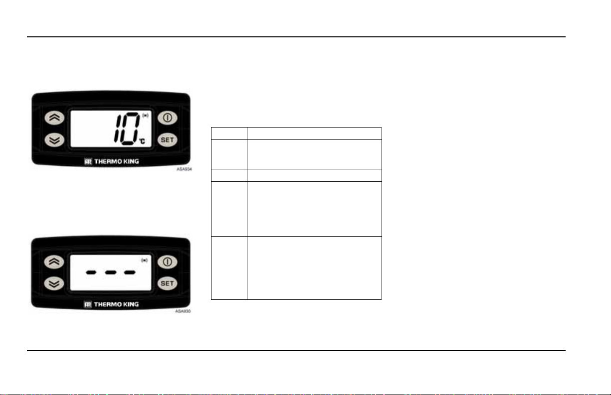
ISTRUZIONI OPERATIVE
Avviamento automatico:
l'allarme arresta l'unità, sullo schermo compare il
simbolo di ALLARME e l'unità si avvia
automaticamente dopo che la condizione di
allarme è stata rettificata.
Qualora si verificasse un allarme P1E - codice di
allarme errore lettura temperatura aria di ritorno,
sullo schermo comparirà --- assieme al simbolo
dell'allarme, invece della lettura della temperatura
dell'aria di ritorno.
86
Premere e rilasciare il tasto SET due volte per
visualizzare il codice di allarme attuale sullo
schermo. Se c'è più di un allarme attivo, tutti i
codici di allarme sull'unità possono essere
visualizzati in sequenza premendo e rilasciando
tasti SET e FRECCIA.
i
DESCRIZIONE DEI CODICI
ALLARME
DI
Avvio manuale
bAt Bassa tensione della batteria.
Avviamento automatico
P1E Errore di lettura della temperatura
E7 Errore di comunicazione (non è
Sistema di protezione dell'unità e della
batteria.
dell'aria di ritorno della cella di
carico (circuito aperto o
cortocircuito). Contattare il
concessionario autorizzato al servizio
assistenza.
possibile leggere alcun valore dalla
cabina, ma l'unità continua a
lavorare con il precedente comando
operativo). Contattare il
concessionario autorizzato al servizio
assistenza.
CANCELLAZIONE DEI CODICI
ALLARME
DI
Innanzitutto la condizione di allarme nell'unità deve
essere cancellata. Dopo aver cancellato la condizione
di allarme, premere e rilasciare una volta il tasto SET
per cancellare i codici di ALLARME esistenti.
Quando i codici di ALLARME sono stati cancellati,
comparirà il display standard.
VISUALIZZAZIONE DELLE SCHERMATE DI INFORMAZIONI
MENU PRINCIPALE
Dal
display standard
menu principale
per visualizzare:
1. Allarmi (se attivi)
2. Temperatura del punto di riferimento
3. Sbrinamento manuale dell'evaporatore
Premere il tasto di accensione/spegnimento una volta
per ritornare al display standard.
MENU INFORMAZIONI
Dal
display standard
secondo per aprire il
1
utilizzare il tasto SET per visualizzare:
quindi
1. tSt:
test display (tutte le icone accese).
2. reL:
versione del software.
3. bAt:
tensione attuale della batteria.
4. toH:
tempo totale in cui l’unità è stata in funzione
per proteggere il carico.
5. coH:
numero di ore di funzionamento del
compressore azionato dal motore diesel.
Ritornare al menu principale premendo il tasto
di accensione/spegnimento.
, usare il tasto SET per aprire il
, quindi utilizzare i tasti FRECCIA
, premere il tasto SU per
menu informazioni
,
Page 87

ISTRUZIONI OPERATIVE
Nota: i contaore verranno visualizzati in ore, se il
valore conteggiato è inferiore a 1.000.
Se il valore è superiore o uguale a 1.000, il numero di
ore verrà visualizzato alternativamente in or e e
migliaia nelle cartelle "toh" e "coh".
Ad esempio, se il valore conteggiato è 12.055,
verranno visualizzati alternativamente "055" e
"12"; il numero a tre cifre è sempre il numero delle
"ore", mentre quello a due cifre è il numero delle
"migliaia di ore".
ISPEZIONE POST-AVVIAMENTO
Termostato:
di sopra e al di sotto della temperatura del vano per
controllare il funzionamento del termostato (vedi
modalità operative).
Preraffreddamento:
temperatura desiderata, far funzionare l'unità per un
tempo compreso tra mezz'ora e un'ora (o
se possibile) prima di caricare l'autocarro.
preraffreddamento elimina il calore residuo e
Il
costituisce un buon test del sistema di refrigerazione.
Sbrinamento:
preraffreddamento dell'interno dell'autocarro -
temperatura dell'evaporatore dovrebbe essere scesa
la
al di sotto di 2 ºC (35,6 ºF) - avviare un ciclo di
sbrinamento con l'interruttore di sbrinamento manuale.
Il ciclo di sbrinamento dovrebbe concludersi
automaticamente.
regolare l'impostazione del termostato al
con il termostato impostato alla
più a lungo
quando l'unità ha terminato il
PROCEDURA DI CARICO
1. Per ridurre al minimo l'accumulo di brina sulla
serpentina dell'evaporatore e un aumento di calore
all'interno del vano di carico, assicurarsi che l'unità
sia spenta prima di aprire gli sportelli (l’unità può
essere mantenuta in funzione quando vengono
effettuate operazioni di carico su un autocarro in un
deposito a porte chiuse).
2. V erificare e registrare con attenzione la temperatura
delle merci durante le operazioni di carico
dell’autocarro. V erificare che nessun prodotto sia
fuori dalla gamma della temperatura.
3. Caricare il prodotto in modo tale che ci sia spazio a
sufficienza affinché l'aria circoli attraverso il carico.
NON bloccare l’entrata e l’uscita dell’evaporatore.
4. I prodotti vanno raffreddati prima di essere caricati.
Le unità Thermo King sono progettate per
mantenere il carico alla temperatura alla quale è
stato caricato. Le unità di refrigerazione per il
trasporto non sono progettate per ridurre la
temperatura del carico.
PROCEDURA POST-CARICO
1. Accertarsi che tutti gli sportelli siano chiusi e
bloccati.
2. Regolare il termostato sulla temperatura di
riferimento desiderata.
3. Avviare l'unità.
4. Mezz'ora dopo aver caricato l'autocarro, sbrinare
l'unità per un attimo premendo l'interruttore di
sbrinamento manuale. Se la temperatura della
serpentina scende al di sotto di 2 ºC (35,6 ºF), l'unità
si sbrinerà. Il ciclo di sbrinamento dovrebbe
concludersi automaticamente.
VERIFICHE SETTIMANALI PRIMA DELLA PARTENZA
1. Ispezionare visivamente la cinghia.
2. Individuare eventuali rumori inconsueti, vibrazioni,
ecc.
3. Ispezionare l'unità e assicurarsi che non vi siano
perdite di liquidi (liquido di raffreddamento, olio,
refrigerante).
4. Ispezionare visivamente l'unità alla ricerca di pezzi
danneggiati, allentati o rotti (comprese le eventuali
condutture dell'aria e le paratie).
5. In presenza di quantità eccessive di sporco o di
ostruzioni, pulire l'unità e anche le serpentine del
condensatore e dell'evaporatore.
VERIFICHE SETTIMANALI DOPO
PARTENZA
LA
1. Pulire il rivestimento esterno dell’unità utilizzando
un panno umido e del detergente neutro.
utilizzare solventi o prodotti abrasivi.
Non
Non utilizzare acqua pressurizzata.
2. Ispezionare l’unità per rilevare eventuali perdite.
3. Controllare la struttura per individuare eventuali
pezzi allentati o mancanti.
4. Accertarsi che l’unità non presenti danni strutturali.
ATTENZIONE
87
Page 88
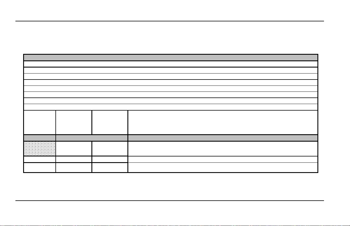
PROGRAMMA DELLE ISPEZIONI E DEGLI INTERVENTI DI MANUTENZIONE
MODELLI DELLE UNITÀ Gamma VP
Consigliata ispezione prima settimana
DOPO LA PRIMA SETTIMANA di funzionamento:
• Controllare la tensione della cinghia
• Serrare i bulloni di montaggio dell'unità e del supporto di montaggio
• Controllare i cavi e i tubi al fine di individuare eventuali segni di sfregamento
•
Controllare i tubi e i raccordi al fine di accertarsi che non vi siano perdite
Consigliato A B
Ogni 500 ore Ogni 1.500 ore Ogni 3.000 ore
OO O
6 mesi 12 mesi 24 mesi
arie Tali procedure possono essere eseguite in aggiunta a quelle di manutenzione standard.
5 5
* Controllare la calibrazione dei sensori di mandata e di ritorno, annualmente o come da normativa HACCP.
Verificare, se installati, anche i registratori stand-alone. Il collaudo non è incluso nella manutenzione.
5 5 5
Verificare il funzionamento di tutti gli accessori
.
5 5 5
Verificare i registri degli interventi di assistenza e assicurarsi che la manutenzione e le modifiche di garanzia
siano state completate (aggiornamenti non inclusi).
Ispezioni/riparazioni da effettuare
PROGRAMMA DELLE ISPEZIONI E DEGLI INTERVENTI DI MANUTENZIONE
La stretta aderenza a un programma di manutenzione contribuirà a mantenere la vostra unità Thermo King in perfette condizioni di funzionamento. La seguente
tabella generale fornisce un supporto al programma di manutenzione.
V
88
Le procedure da eseguire dip endono dal modello.
Page 89

PROGRAMMA DELLE ISPEZIONI E DEGLI INTERVENTI DI MANUTENZIONE
MODELLI DELLE UNITÀ Gamma VP
Consigliato A B
Ogni 500 ore Ogni 1.500 ore Ogni 3.000 ore
OO O
6 mesi 12 mesi 24 mesi
Sistema elettrico
5 5 5
Download del registratore dati - Controllare i codici di allarme e il funzionamento del sistema e correggere le
eventuali anomalie (ove possibile).
5 5 5
Controllare l’avvio e il completamento dello sbrinamento. Controllare il funzionamento dei ventilatori
dell'evaporatore durante lo sbrinamento (i ventilatori devono essere spenti durante lo sbrinamento).
5 5 5
Controllare la sequenza dell’interruttore del termostato.
5 5
Controllare i dispositivi di sicurezza nei circuiti di chiusura.
5 5
Controllare il termostato e la calibrazione del sensore di temperatura.
5 5
Controllare i collegamenti alle spine e i cavi al fine di verificare che non siano allentati.
5 5 5
Controllare i cavi e i fili al fine di individuare eventuali segni di sfregamento.
5 5 5
Controllare il funzionamento delle ventole del condensatore e dell'evaporatore.
5 5
Verificare le spazzole del motore a CC. Sostituirle entro le 2.000 ore (se la prossima ispezione di manutenzione
sarà dopo le 2.000 ore, sostituirle in tale occasione).
5 5 5
Verificare il funzionamento di tutti i componenti accessori esterni Thermo King.
5 5 5
Verificare il funzionamento di tutti i componenti accessori esterni non Thermo King.
Struttura
5 5 5
Ispezionare visivamente l’unità per individuare eventuali parti danneggiate, allentate o rotte.
5 5
Pulire gli scarichi di sbrinamento.
5 5
Pulire le serpentine dell'evaporatore e del condensatore e il dissipatore di calore del raddrizzatore a ponte.
5 5
Controllare tutti i bulloni di montaggio, i supporti, le linee, i tubi, ecc.
Ispezioni/riparazioni da effettuare
Il tecnico della manutenzione è tenuto a valutare le condizioni di tutte le parti e i componenti rilevati durante le operazioni di manutenzione, in
modo da garantire il loro adeguato funzionamento fino al prossimo intervento programmato. Le parti che non risultano essere in buone
condizioni devono essere sostituite.
89
Page 90

PROGRAMMA DELLE ISPEZIONI E DEGLI INTERVENTI DI MANUTENZIONE
MODELLI DELLE UNITÀ Gamma VP
Consigliato A B
Ogni 500 ore Ogni 1.500 ore Ogni 3.000 ore
OOO
6 mesi 12 mesi 24 mesi
Impianto di refrigerazione
5 5 5
Eseguire un'ispezione visiva di tubi e raccordi del refrigerante al fine di accertarsi che non vi siano perdite.
5 5 5
Eseguire un'ispezione visiva di tubi e raccordi del refrigerante al fine di individuare segni di sfregamento.
5 5 5
Verificare il direzionamento dei tubi del refrigerante nel compressore principale.
5 5 5
Controllare la carica del refrigerante.
5 5
Verificare le valvole di regolazione della pressione.
5
Sostituire il disidratatore.
5 5
Ispezionare il separatore d'olio.
5
Controllare il filtro della presa di aspirazione del compressore quando si sostituisce il disidratatore (oppure
quando si apre il sistema per altri motivi).
5 5 5
Controllare il funzionamento della frizione del compressore
5 5
Verificare che la temperatura cambi durante i cicli di riscaldamento e raffreddamento (riscaldamento ove
presente).
5 5
Controllare la validità del certificato dei gas fluorurati secondo le normative vigenti (la certificazione non è inclus
a
nella manutenzione preventiva).
Adattatore kit di trasmissione (fare riferimento ai consigli del produttore per la manutenzione)
5 5
Eseguire un'ispezione visiva del kit di montaggio del compressore e dei componenti associati.
5 5
Verificare che tutti i bulloni dell’adattatore siano opportunamente serrati.
5 5
Verificare che non vi siano vibrazioni anomale.
5
Sostituire la cinghia secondo le raccomandazioni del produttore.
5 5
Controllare la tensione e lo stato delle cinghie secondo le raccomandazioni del produttore.
Ispezioni/riparazioni da effettuare
90
Page 91

GARANZIA
GARANZIA
Per ricevere assistenza durante il periodo di
garanzia è sufficiente presentare copia del
Certificato di garanzia a un concessionario
Thermo King in una delle località elencate nel
Registro di assistenza Thermo King.
concessionari saranno lieti di prestare assistenza
I
ai clienti alle condizioni indicate di seguito.
COMPENDIO DI GARANZIA
Le condizioni della garanzia limitata
King sono disponibili presso
Thermo
il concessionario Thermo King.
Nota: le sostituzioni o riparazioni di componenti
in garanzia devono essere eseguite da un
concessionario Thermo King autorizzato.
Nota: termini e periodi di garanzia sono soggetti a
modifiche. La garanzia specifica applicabile
all'unità può essere verificata presso il
concessionario Thermo King.
RECUPERO DEL REFRIGERANTE
In Thermo King siamo consapevoli della
necessità di preservare l'ambiente e di limitare il
potenziale danneggiamento dello strato di ozono
derivante dal rilascio di refrigerante
nell'atmosfera. Adottiamo quindi una rigorosa
politica atta a promuovere il recupero di
refrigeranti e a limitarne la dispersione
nell'atmosfera.
91
Page 92

GARANZIA
92
Page 93

Bedieningshandleiding Ce-serie
TK 60980-NL-18-OP (versie 3, 04/16)
Page 94

NEDERLANDS INHOUDSOPGAVE
Inleiding . . . . . . . . . . . . . . . . . . . . . . . . . . . . . . . . . . . . . . . . . . . . . . . . . . . . . . . . . . . . . . . . . . . . . . . . . . . . . . . . . . . . . 95
Algemeen. . . . . . . . . . . . . . . . . . . . . . . . . . . . . . . . . . . . . . . . . . . . . . . . . . . . . . . . . . . . . . . . . . . . . . . . . . . . . . . . . . . . . . .96
Veiligheidsmaatregelen. . . . . . . . . . . . . . . . . . . . . . . . . . . . . . . . . . . . . . . . . . . . . . . . . . . . . . . . . . . . . . . . . . . . . . . . . 97
Koudemiddel . . . . . . . . . . . . . . . . . . . . . . . . . . . . . . . . . . . . . . . . . . . . . . . . . . . . . . . . . . . . . . . . . . . . . . . . . . . . . . . . . . . .97
Eerste hulp - Koudemiddel. . . . . . . . . . . . . . . . . . . . . . . . . . . . . . . . . . . . . . . . . . . . . . . . . . . . . . . . . . . . . . . . . . . . . . . . . .97
Koudemiddelolie. . . . . . . . . . . . . . . . . . . . . . . . . . . . . . . . . . . . . . . . . . . . . . . . . . . . . . . . . . . . . . . . . . . . . . . . . . . . . . . . . .97
Eerste hulp - Koudemiddelolie . . . . . . . . . . . . . . . . . . . . . . . . . . . . . . . . . . . . . . . . . . . . . . . . . . . . . . . . . . . . . . . . . . . . . . .97
Automatisch starten . . . . . . . . . . . . . . . . . . . . . . . . . . . . . . . . . . . . . . . . . . . . . . . . . . . . . . . . . . . . . . . . . . . . . . . . . . . . . . .98
Elektrisch gevaar . . . . . . . . . . . . . . . . . . . . . . . . . . . . . . . . . . . . . . . . . . . . . . . . . . . . . . . . . . . . . . . . . . . . . . . . . . . . . . . . .98
Elektrisch bedieningssysteem . . . . . . . . . . . . . . . . . . . . . . . . . . . . . . . . . . . . . . . . . . . . . . . . . . . . . . . . . . . . . . . . . . . 99
Beschrijving van het elektronisch bedieningssysteem . . . . . . . . . . . . . . . . . . . . . . . . . . . . . . . . . . . . . . . . . . . . . . . . . . . . .99
Bediening van de unit. . . . . . . . . . . . . . . . . . . . . . . . . . . . . . . . . . . . . . . . . . . . . . . . . . . . . . . . . . . . . . . . . . . . . . . . . . . . .100
Gebruiksaanwijzing. . . . . . . . . . . . . . . . . . . . . . . . . . . . . . . . . . . . . . . . . . . . . . . . . . . . . . . . . . . . . . . . . . . . . . . . . . . 101
Wekelijkse controle voorafgaand aan een rit . . . . . . . . . . . . . . . . . . . . . . . . . . . . . . . . . . . . . . . . . . . . . . . . . . . . . . . . . . .101
De unit starten . . . . . . . . . . . . . . . . . . . . . . . . . . . . . . . . . . . . . . . . . . . . . . . . . . . . . . . . . . . . . . . . . . . . . . . . . . . . . . . . . .102
Standaarddisplay . . . . . . . . . . . . . . . . . . . . . . . . . . . . . . . . . . . . . . . . . . . . . . . . . . . . . . . . . . . . . . . . . . . . . . . . . . . . . . . .102
Het instelpunt van de temperatuur invoeren . . . . . . . . . . . . . . . . . . . . . . . . . . . . . . . . . . . . . . . . . . . . . . . . . . . . . . . . . . .102
De handbediende ontdooicyclus van de verdamper starten . . . . . . . . . . . . . . . . . . . . . . . . . . . . . . . . . . . . . . . . . . . . . . .103
Alarmen . . . . . . . . . . . . . . . . . . . . . . . . . . . . . . . . . . . . . . . . . . . . . . . . . . . . . . . . . . . . . . . . . . . . . . . . . . . . . . . . . . . . . . .103
Beschrijving alarmcodes . . . . . . . . . . . . . . . . . . . . . . . . . . . . . . . . . . . . . . . . . . . . . . . . . . . . . . . . . . . . . . . . . . . . . . . . . .104
Alarmcodes wissen . . . . . . . . . . . . . . . . . . . . . . . . . . . . . . . . . . . . . . . . . . . . . . . . . . . . . . . . . . . . . . . . . . . . . . . . . . . . . .104
Informatieschermen weergeven. . . . . . . . . . . . . . . . . . . . . . . . . . . . . . . . . . . . . . . . . . . . . . . . . . . . . . . . . . . . . . . . . . . . .104
Controle na starten. . . . . . . . . . . . . . . . . . . . . . . . . . . . . . . . . . . . . . . . . . . . . . . . . . . . . . . . . . . . . . . . . . . . . . . . . . . . . . .105
Laadprocedure. . . . . . . . . . . . . . . . . . . . . . . . . . . . . . . . . . . . . . . . . . . . . . . . . . . . . . . . . . . . . . . . . . . . . . . . . . . . . . . . . .105
Procedure na koelen . . . . . . . . . . . . . . . . . . . . . . . . . . . . . . . . . . . . . . . . . . . . . . . . . . . . . . . . . . . . . . . . . . . . . . . . . . . . .105
Wekelijkse controle voorafgaand aan een rit . . . . . . . . . . . . . . . . . . . . . . . . . . . . . . . . . . . . . . . . . . . . . . . . . . . . . . . . . . .105
Wekelijkse controle na een rit . . . . . . . . . . . . . . . . . . . . . . . . . . . . . . . . . . . . . . . . . . . . . . . . . . . . . . . . . . . . . . . . . . . . . .105
Onderhoudinspectieschema . . . . . . . . . . . . . . . . . . . . . . . . . . . . . . . . . . . . . . . . . . . . . . . . . . . . . . . . . . . . . . . . . . . 106
Garantie . . . . . . . . . . . . . . . . . . . . . . . . . . . . . . . . . . . . . . . . . . . . . . . . . . . . . . . . . . . . . . . . . . . . . . . . . . . . . . . . . . . . 109
94
Page 95

INLEIDING
THERMO ASSISTANCE
Thermo Assistance is een communicatiemiddel
in meerdere talen waarmee u, indien nodig,
rechtstreeks contact kunt opnemen met een
erkende servicedealer.
Om gebruik te maken van dit systeem moet u als u
belt, de volgende informatie bij de hand hebben:
• Telefoonnummer waarop wij u kunnen
bereiken
• Type van de TK-unit
• Instelling van de thermostaat
• Huidige temperatuur van de lading
• Mogelijke oorzaak van de storing
• Zit er garantie op de unit?
• Hoe gaat u de reparatie betalen?
Raadpleeg de Thermo King Service Directory.
Geef uw naam op aan de medewerker van
Thermo Assistance evenals het telefoonnummer
waarop wij u kunnen bereiken, en vraag de
medewerker u terug te bellen. Thermo Assistance
belt u vervolgens terug. U kunt dan
bijzonderheden over de gewenste assistentie
verstrekken, waarna voor de reparatie zal worden
gezorgd.
Thermo Assistance kan niet voor de betaling
zorgdragen. Deze service is uitsluitend bedoeld
voor koelwagens die zijn uitgerust met door
Thermo King Corporation geproduceerde
producten.
DISCLAIMER
De fabrikant, Thermo King Corporation, is niet
verantwoordelijk voor enige daad of handeling
door de eigenaar of gebruiker bij reparaties of
gebruik van de in deze handleiding beschreven
producten die in strijd is met de gedrukte
instructies van de fabrikant. Er is geen garantie,
expliciet noch impliciet, noch een garantie
resulterend uit verdeling, gebruik of handel, met
betrekking tot de informatie, de aanbevelingen
en omschrijvingen die hierin gegeven worden.
De fabrikant is niet verantwoordelijk en kan niet
aansprakelijk worden gesteld als gevolg van
contract of gerechtelijk vervolgbare benadeling
(inclusief nalatigheid) voor enige speciale,
indirecte of gevolgschade, met inbegrip van
letsel of schade berokkend aan voertuigen,
inhoud of personen, veroorzaakt door installatie
van een Thermo King-product of het mechanisch
falen daarvan, of het in gebreke blijven van de
eigenaar of gebruiker om de waarschuwings- en
veiligheidsstickers die op het product zijn
aangebracht, in acht te nemen.
INLEIDING
Thermo King Spain heeft een nieuw, digitaal
bedieningskastje met een programmeerbare
microprocessor ontworpen die de werking van de
unit monitort en deze informatie snel en duidelijk
op het scherm weergeeft.
Deze nieuwe bedieningskastjes zijn bedoeld voor
gebruik in units uit de Thermo King eC-serie.
Het is niet moeilijk om te leren hoe u de
bedieningskastjes van Thermo King Spain moet
gebruiken, maar het is zeker de moeite waard
deze handleiding in zijn geheel door te lezen.
om
De bedieningskastjes werken met units van
12 en 24V.
Temperaturen kunnen in Celsius of graden
Fahrenheit worden weergegeven.
Deze handleiding voor de bestuurder is alleen
bedoeld ter informatie. De informatie is niet
noodzakelijkerwijs volledig en niet alle
problemen die zich voor kunnen doen worden
behandeld. Als u meer informatie wilt, kijk dan in
uw Thermo King Service-adreslijst voor het adres
en telefoonnummer van een plaatselijke dealer.
Alle nodige reparaties en onderhoud, groot en
klein, moeten door een Thermo King-dealer
worden uitgevoerd. Daar zijn vier belangrijke
redenen voor:
1. De dealers beschikken over het gereedschap dat
door de fabriek wordt aanbevolen, zodat ze alle
reparaties kunnen uitvoeren.
2. Ze hebben officieel erkende monteurs in dienst
die door de fabriek zijn opgeleid.
95
Page 96
INLEIDING
Temperatuurafname
Instelpunt
temperatuur
Temperatuurtoename
XºC/F boven het
instelpunt
XºC/F onder het
instelpunt
KOELEN
VERWARMEN
NUL-
STAND
3. Ze hebben originele Thermo King-onderdelen
op voorraad.
4. De garantie op de nieuwe unit is van kracht als
de reparatie en/of de vervanging van
onderdelen door een erkende Thermo Kingdealer is uitgevoerd.
Door regelmatig voorafgaand aan een trip
controles uit te voeren, zullen problemen
onderweg tot een minimum beperkt blijven. Als u
zich aan het onderhoudsprogramma houdt, zal dit
er zeker toe bijdragen dat de unit in goede staat
blijft. Als de door de fabriek aanbevolen
procedures worden gevolgd, zult u merken dat u
het meest doelmatige en betrouwbare systeem
voor temperatuurbeheersing op de markt
verkrijgbaar heeft aangeschaft.
ALGEMEEN
Temperatuurbeheer is voor door een vrachtwagen
aangedreven unit gebaseerd op twee waarden: de
instelling (het instelpunt) van de elektronische
thermostaat en de temperatuur van de retourlucht
van de verdamper. Het verschil tussen deze
temperaturen is bepalend voor de stand waarin de
unit werkt: koelen, verwarmen of nul.
• Koelen: Als de temperatuur in de laadruimte
hoger is dan het instelpunt, werkt de unit in de
koelstand om de temperatuur van de retourlucht
van de verdamper te verlagen.
• Verwarmen: Als de temperatuur in de
laadruimte lager is dan het instelpunt, werkt de
unit in de verwarmingstand om de temperatuur
van de retourlucht van de verdamper te
verhogen.
• Nul: Zodra de temperatuur gelijk is aan het
instelpunt en daar vervolgens niet meer dan
XºC/F boven komt, is er geen behoefte aan
koude lucht en draait de unit in de nulstand.
• Ontdooien: Na een ingestelde periode in de
koelstand, tussen 30 minuten en 8 uur, loopt de
unit in deze vierde bedieningsmodus om ijs te
verwijderen dat is ontstaan in de verdamper of
condensorbuis. De ontdooifunctie kan
automatisch of handmatig worden gestart.
Fabrieksinstelling voor X is 3ºC (5ºF). Tijdens
installatie van de unit kan de waarde worden
aangepast in stappen van 1ºC/F.
Units met R-134a-koudemiddel zonder
ontdooifunctie: De temperatuur kan worden
ingesteld van 0ºC tot +22ºC (+32ºF tot +71ºF).
Units met R-134a-koudemiddel met
ontdooifunctie: De temperatuur kan worden
ingesteld van -10ºC tot +22ºC (+14ºF tot +71ºF).
Units met R-404A-koudemiddel: De temperatuur
kan worden ingesteld van -32ºC tot +22ºC (-26ºF
tot +71ºF).
Adres:
Sant Josep, 140-142 P.I.
Pla”, Sant Feliu de
“El
Llobregat, Barcelona, Spanje.
Bouwjaar: zie het plaatje met het serienummer.
De installatie en in werking stelling moeten in
overeenstemming met de werkwijze en
tekeningen van Thermo King door een erkende
Thermo King-dealer worden uitgevoerd.
Uitzonderingen hierop zijn alleen mogelijk met
schriftelijke toestemming van de fabrikant.
96
Page 97

VEILIGHEIDSMAATREGELEN
VEILIGHEIDSMAATREGELEN
WAARSCHUWING!
De unit is niet bedoeld voor gebruik door personen
(waaronder kinderen) met een fysieke, zintuigelijke,
of mentale afwijking, of door personen zonder d e
juiste ervaring en kennis, tenzij ze onder
begeleiding zijn of instructies hebben ontvangen
over het gebruik van de unit door iemand die
verantwoordelijk is voor hun veiligheid.
Kinderen moeten onder toezicht zijn om ervoor te
zorgen dat ze niet met unit gaan spelen.
Thermo King raadt aan om alle reparaties en
onderhoud door een Thermo King-dealer uit te
voeren. U dient z elf ech ter een aant al algem ene
veiligheidsmaatregelen in acht te
nemen:
1. Wanneer u aan of in de nabijheid van het
koelsysteem of de accu werkt, moet u altijd een
veiligheidsbril dragen. Als uw ogen in aanraking
komen met koudemiddel of accuzuur, kan dit tot
blijvende schade leiden.
2. Gebruik de unit nooit wanneer de afvoerklep van de
compressor gesloten is.
3. Houd uw handen of losse kleding te allen tijde uit
de buurt van de ventilatoren en het
aandrijfmechanisme wanneer de unit draait of
wanneer u de onderhoudskleppen van de
compressor opent of sluit.
laten
4. Indien u om welke reden dan ook gaten in de unit
moet boren, dient u uiterst voorzichtig te werk te
gaan. U kunt daarbij namelijk structurele
onderdelen verzwakken. Boren in elektrische
leidingen of koudemiddelbuizen kan brand
veroorzaken.
5. Wij raden aan om alle reparaties en onderhoud aan
de verdamperspiralen en condensorbuizen door
erkende monteurs van Thermo King te laten
uitvoeren. Indien u toch in de buurt van de spiralen
en buizen moet werken, dient u uitermate
voorzichtig te werk te gaan. Aanraking met de
bladen van de spiralen en buizen kan namelijk
pijnlijke wonden tot gevolg hebben.
KOUDEMIDDEL
Hoewel koudemiddelen op basis van fluorkoolstof
over het algemeen veilig zijn, is voorzichtigheid
geboden wanneer u met koudemiddelen werkt of
onderhoud verricht in delen van de unit waar deze
gebruikt worden.
Koudemiddelen op basis van fluorkoolstoffen
verdampen snel, waardoor alles waarmee ze in
aanraking komen als ze per ongeluk vanuit vloeibare
vorm in de atmosfeer vrijkomen, bevriest.
Koudemiddelen op basis van fluorkoolstoffen die in
airconditioning worden gebruikt, kunnen giftige
gassen veroorzaken die bij open vuur of in het geval
van kortsluiting uitermate irriterend zijn voor de
luchtwegen, mogelijk met de dood als gevolg.
EERSTE HULP - KOUDEMIDDEL
OGEN:
Als vloeistof in aanraking met de ogen komt,
dienen deze onmiddellijk met veel water gespoeld te
worden en dient er direct medische hulp ingeroepen te
worden.
HUID:
Spoel het desbetreffende deel van de huid met
grote hoeveelheden lauw water en houd de huid koel.
Wikkel de brandwonden in droog, steriel, dik verband
ter bescherming tegen infectie/letsel. Schakel
medische hulp in.
BIJ INADEMING:
Zorg dat het sla chto ffe r frisse lu cht
krijgt, en beadem hem indien nodig. Blijf bij het
slachtoffer tot medische hulp arriveert.
KOUDEMIDDELOLIE
Neem de volgende voorzorgsmaatregelen in acht als u
met koudemiddelolie werkt:
OGEN:
Laat geen koudemiddel in uw ogen komen.
HUID:
Vermijd langdurige of herhaalde aanraking met
huid of kleding.
IRRITATIE:
W as uw handen goed als u met de olie
heeft gewerkt. Zo voorkomt u irritatie.
EERSTE HULP - KOUDEMIDDELOLIE
OGEN:
Spoel de ogen, met de oogleden geopend,
onmiddellijk gedurende ten minste 15 minuten met
grote hoeveelheden water. Roep onmiddellijk
medische hulp in.
97
Page 98

VEILIGHEIDSMAATREGELEN
HUID:
Besmette kleding verwijderen. W as d e huid
grondig met water en zeep. Zoek medische hulp als de
irritatie voortduurt.
BIJ INADEMING:
Zorg dat het slachtoffer frisse lucht
krijgt, en beadem hem indien nodig. Blijf bij het
slachtoffer tot medische hulp ter plaatse is.
OPNAME:
W ek braken niet op. Neem direct contact
op met het Nationaal Vergiftigingen
Informatiecentrum of een arts.
Koudemiddelen op basis van fluorkoolstoffen
vervangen zuurstof en kunnen derhalve tot een
tekort aan zuurstof leiden met als mogelijk gevolg
dood door verstikking. Bij het werken met of bij
koudemiddelen of airconditioningssystemen die
koudemiddelen bevatten, is steeds uiterste
voorzichtigheid geboden. Dit geldt met name in
afgesloten of kleine ruimten.
AUTOMATISCH STARTEN
Door een vrachtwagen aangedreven koelunits van
Thermo King kunnen op ieder moment
automatisch gestart worden.
Zorg ervoor dat de unit is uitgeschakeld voordat u
een component controleert.
ELEKTRISCH GEVAAR
Zorg ervoor dat de stroomtoevoer onder
hoogspanning is uitgeschakeld en ontkoppel de
stroomkabel voordat u aan de unit gaat werken.
Units met elektrische stroomtoevoer kunnen een
gevaar vormen vanwege de elektriciteit.
Elektrisch lassen wekt hoge
stroomsterktespanningen op die elektrische
en elektronische onderdelen kunnen
beschadigen. Om schade tot een minimum te
beperken moeten, voorafgaand aan enig
laswerk aan het voertuig, de el ektrische
aansluitingen van de microprocessor en de
accu van de unit van het voertuig word e n
ontkoppeld. Schakel de aan-/uitschakelaar van
de microprocessor uit Verwijder de negatieve
accukabel. Maak alle stekkers aan de
achterzijde van de microprocessor-controller
los. Sluit de bedieningskast. Sluit de aarddraad
van het lasapparaat zo dicht mogelijk bij het
gedeelte waar wordt gelast, aan. Verwijder de
aarding van het lasapparaat wanneer het
lassen is voltooid. Sluit de stekkers weer op de
achterzijde van de microprocessor-controller
aan. Sluit de negatieve accukabel weer aan.
Zet de aan/uit-schakelaar van de
microprocessor aan. Stel alle alarmen en
coderingen opnieuw op hun voorgaande
instellingen in. Voer een volledige controle
vóór de rit uit. Uitgebreide instructies vindt u in
de ‘Thermo King-serviceprocedure A26A’.
WAARSCHUWING
98
Page 99

ELEKTRISCH BEDIENINGSSYSTEEM
Koelunits met directe aandrijving van
King bestaan uit een condensator,
Thermo
verdamper, een voertuigcompressor en een
bedieningspaneel (bedieningskastje) waarmee
unit bediend wordt.
de
Het elektrische bedieningssysteem bestaat uit een
elektrische bedieningsmodule (in de condensator)
en het bedieningskastje. Met het bedieningskastje
kan de vrachtwagenchauffeur de koelunit van
Thermo King bedienen.
Bedieningskastje
BESCHRIJVING VAN HET ELEKTRONISCH BEDIENINGSSYSTEEM
Het elektronisch bedieningssysteem heeft de
volgende functies:
• Automatisch starten
• Vertraagd starten
• Actieve weergave
• Alarm voor lage accuspanning
• Weergave waarde accuspanning
• Unitbediening zonder bedieningskastje
• Handmatig of automatisch ontdooien
• Temperatuursensor retourlucht
• Instelpunt temperatuur
Automatisch starten: Als de stroom uitvalt
wanneer de unit is ingeschakeld, wordt de unit
weer ingeschakeld zodra de stroom weer is
ingeschakeld.
Vertraagd starten: Na een automatische start
blijft de unit een aantal seconden inactief.
Actieve weergave: Het bedieningskastje is altijd
actief, behalve als de unit is ontkoppeld (geen
stroom) of als de unit is aangesloten, maar
handmatig is uitgeschakeld met het
bedieningskastje (als er geen actief alarm is).
Uren
teller:
Totaal aantal uren dat de unit in b edrijf is.
Urenteller voertuigcompressor: Aantal uren dat
de unit onderweg in bedrijf is.
Alarm voor lage accuspanning: Ontkoppel de
unit als de accuspanning te laag is.
ELEKTRISCH BEDIENINGSSYSTEEM
Weergave waarde accuspanning: De waarde van
de accuspanning wordt in het informatiemenu
weergegeven.
Unitbediening zonder bedieningskastje: Deze
unit kan ook bediend worden met het elektrische
bedieningssysteem zonder het bedieningskastje,
onder voorwaarden die met het bedieningskastje
zijn ingesteld voordat deze wordt ontkoppeld.
Handmatig of automatisch ontdooien: Er kan
gekozen worden voor handmatig en automatisch
ontdooien en het de ontdooitijd kan in de
automatische ontdooistand worden geselecteerd.
Temperatuursensor retourlucht: De temperatuur
in de laadruimte wordt op het scherm
weergegeven.
Instelpunt temperatuur: Het instelpunt van de
temperatuur wordt op het scherm weergegeven.
99
Page 100

ELEKTRISCH BEDIENINGSSYSTEEM
BEDIENING VAN DE UNIT
WAARSCHUWING:
Bedien de unit nooit als u niet volledig op de
hoogte bent van de bediening; ander kan er
ernstig letsel optreden.
BEDIENINGSKASTJE
Display, toetsen en symbolen
1. Display. Het display is altijd actief, behalve als
de unit is losgekoppeld (geen stroom) of als de
unit is aangesloten, maar handmatig is
uitgeschakeld met het bedieningskastje.
gesproken geeft het de
Normaal
retourluchttemperatuur weer.
2. AAN/UIT-toets. Deze toets wordt gebruikt om
de unit te starten/stoppen door de toets ten minste
1 seconde ingedrukt te houden. Druk eenmaal in
om terug te gaan naar het vorige menu.
3. Toets Set (Instellen). Hiermee selecteert u de
prompt- en informatieschermen. Eén keer
indrukken: naar het volgende menu gaan.
4. Toets Omhoog. Wordt gebruikt om het
instelpunt van de temperatuur te verhogen,
waarden weer te geven en omhoog te scrollen in
een menu.
5. Toets Omlaag. Wordt gebruikt om het
instelpunt van de temperatuur te verlagen,
waarden weer te geven en omlaag te scrollen in
een menu.
6. Symbool Koelen. De unit is aan het koelen.
7. Symbool Verwarmen. De unit is aan het
verwarmen.
8. ºC/ºF weergave. Geeft aan of de temperatuur
op het scherm in graden Celsius (ºC) of graden
Fahrenheit (ºF) wordt weergegeven.
9. Alarmsymbool. Geeft aan dat er een alarm is in
het systeem.
10. Symbool Ontdooien. Geeft aan dat de
verdamper in de ontdooistand staat.
11. Stip symbool (decimaal). Geeft het vermogen
aan, uitsluitend wanneer de unit is uitgeschakeld.
100
 Loading...