

Page 1

Installation Manual
B-100
Model 10 and 20 with Direct Smart Reefer
TK-54436 -18-IM (Rev. 1,11/09)
Copyright© 2009 Thermo King Corp., Minneapolis, MN, U.S.A.
Page 2

2
Release History
Original (7/09) Released
Rev. 1 (11/09) Page 40, changed text from “start-up wire fuse” to “fused ignition circuit”
Page 3

3
Introduction
This installation manual was written to help assist with the installation of Thermo King refrigeration units powered by vehicle batteries onto either a truck or
a van. The manual comprises sections on condenser, evaporator and other modules that are mounted on the truck or van body, as well as sections on
components and wiring that are to be connected to the vehicle engine from which the unit derives power. Due to its complexity, do not attempt this installation
unless you:
• Are an experienced mechanic.
• Can safely lift 34 kg (75 lb.).
• Are certified or approved in the repair and maintenance of transport refrigeration systems.
• Have a basic understanding of electricity and electrical wiring.
• Have the necessary tools and equipment to complete the installation.
• Have a truck body designed and built to meet the requirements of this installation.
This manual is published for informational purposes only. Thermo King makes no representations or warranties, express or implied, with respect to the
information, recommendations and descriptions contained herein. Information provided should not be regarded as all-inclusive or covering all contingencies.
If further information is required, Thermo King Corporation Service Department should be contacted.
Thermo King’s warranty shall not apply to any equipment which has been “so installed, maintained, repaired or altered as, in the manufacturer’s judgment, to
affect its integrity”.
Manufacturer shall have no liability to any person or entity for any personal injury, property damage or any other direct, indirect, special, or
consequential damages whatsoever, arising out of the use of this manual or any information, recommendations or descriptions contained herein.
Page 4

4
Table of Contents
Introduction . . . . . . . . . . . . . . . . . . . . . . . . . . . . . . . . . . . . . . . . . . . . . . . . . . . . 3
Safety Precautions . . . . . . . . . . . . . . . . . . . . . . . . . . . . . . . . . . . . . . . . . . . . . . 5
Required Tools . . . . . . . . . . . . . . . . . . . . . . . . . . . . . . . . . . . . . . . . . . . . . . . . . 8
Operating Method . . . . . . . . . . . . . . . . . . . . . . . . . . . . . . . . . . . . . . . . . . . . . . 10
Unpacking and Inspecting the Unit . . . . . . . . . . . . . . . . . . . . . . . . . . . . . . . . 11
Installing the Condenser Unit (roof-mounted) . . . . . . . . . . . . . . . . . . . . . . . 12
Installing the Condenser Unit (front-mounted) . . . . . . . . . . . . . . . . . . . . . . . 16
Installing the ES100 Evaporator Unit . . . . . . . . . . . . . . . . . . . . . . . . . . . . . . . 20
Preparing Refrigeration Hoses . . . . . . . . . . . . . . . . . . . . . . . . . . . . . . . . . . . . 22
Connecting Hoses to the Condenser Unit . . . . . . . . . . . . . . . . . . . . . . . . . . 24
Connecting Hoses to the ES100 Evaporator . . . . . . . . . . . . . . . . . . . . . . . . 26
Electrical Connections in the ES100 Evaporator . . . . . . . . . . . . . . . . . . . . . 28
Drain Circuit in the ES100 Evaporator . . . . . . . . . . . . . . . . . . . . . . . . . . . . . . 30
Circuit Seal Test . . . . . . . . . . . . . . . . . . . . . . . . . . . . . . . . . . . . . . . . . . . . . . . 32
In Case of Leaks . . . . . . . . . . . . . . . . . . . . . . . . . . . . . . . . . . . . . . . . . . . . . . . 34
Installing the In-Cab Control . . . . . . . . . . . . . . . . . . . . . . . . . . . . . . . . . . . . . 36
Optional Internal DIN Adaptor . . . . . . . . . . . . . . . . . . . . . . . . . . . . . . . . . . . . 38
Control Cable Connection . . . . . . . . . . . . . . . . . . . . . . . . . . . . . . . . . . . . . . . 40
Battery Connection . . . . . . . . . . . . . . . . . . . . . . . . . . . . . . . . . . . . . . . . . . . . . 42
Fitting the Power Supply Units with Electric Standby . . . . . . . . . . . . . . . . 44
Door Switch Connection . . . . . . . . . . . . . . . . . . . . . . . . . . . . . . . . . . . . . . . . 46
Installing the Deflector . . . . . . . . . . . . . . . . . . . . . . . . . . . . . . . . . . . . . . . . . . 48
Installing the Hose Covers . . . . . . . . . . . . . . . . . . . . . . . . . . . . . . . . . . . . . . . 50
In-Cab Control Box . . . . . . . . . . . . . . . . . . . . . . . . . . . . . . . . . . . . . . . . . . . . . 52
Checking The Installation . . . . . . . . . . . . . . . . . . . . . . . . . . . . . . . . . . . . . . . 55
Charging The Circuit . . . . . . . . . . . . . . . . . . . . . . . . . . . . . . . . . . . . . . . . . . . 56
Outline Drawings . . . . . . . . . . . . . . . . . . . . . . . . . . . . . . . . . . . . . . . . . . . . . . 58
Page 5

5
Safety Precautions
The symbol appears next to a point that is particularly important.
DANGER: Addresses a circumstance that, if encountered, will lead
to death or serious injury.
WARNING: Addresses a circumstance that, if encountered, might
lead to death or serious injury.
CAUTION: Addresses a circumstance that, if encountered, may
cause damage to equipment or minor injury.
DANGER: Never operate the unit with the discharge valve closed
because it could cause the compressor to explode, causing death
or serious injury.
DANGER: Never apply heat to a sealed refrigeration system or
container because it could explode, causing death or serious injury.
DANGER: Fluorocarbon refrigerants, in the presence of an open
flame or electrical short, produce toxic gases that are severe
respiratory irritants capable of causing death.
DANGER: Be careful when working with a refrigerant or
refrigeration system in any enclosed or confined area with a limited
air supply (i.e., a trailer, container or the hold of a ship). Refrigerant
tends to displace air and can cause oxygen depletion which may
result in death by suffocation.
DANGER: When removing a battery from the Battery Pack,
ALWAYS disconnect the negative battery terminal first. Then
remove the positive terminal. When reconnecting the battery
terminals, connect the positive terminal (+) first, and connect the
negative (-) terminal last.
WARNING: Always wear goggles or safety glasses. Refrigerant
liquid, refrigeration oil, and battery acid can permanently damage
the eyes (see First Aid under Refrigeration Oil).
WARNING: Keep your hands away from fans and belts when the
unit is running. This should also be considered when opening and
closing the compressor service valves.
WARNING: Make sure gauge manifold hoses are in good
condition. Never let them come in contact with a belt, fan motor
pulley, or any hot surface.
WARNING: Make sure all mounting bolts are tight and are of
correct length for their particular application.
WARNING: Never drill holes in the unit unless absolutely
necessary. Holes drilled into the unit may weaken structural
components. Holes drilled into electrical wiring can cause fire or
explosion.
WARNING: Never drill holes in the unit unless absolutely
necessary. Holes drilled into the unit may weaken structural
components. Holes drilled into electrical wiring can cause fire or
explosion.
Page 6

6
Safety Precautions (continued)
Refrigerant
First Aid
• FROST BITE: In the event of frost bite, the objectives of First Aid are
to protect the frozen area from further injury, to warm the affected area
rapidly and to maintain respiration.
• EYES: For contact with liquid, immediately flush eyes with large
amounts of water and get prompt medical attention.
• SKIN: Flush area with large amounts of lukewarm water. Do not apply
heat. Remove contaminated clothing and shoes. Wrap burns with dry,
sterile, bulky dressing to protect from infection/injury. Get medical
attention. Wash contaminated clothing before reuse.
• INHALATION: Move victim to fresh air and use CPR or
mouth-to-mouth ventilation, if necessary. Stay with victim until arrival
of emergency medical personnel.
Refrigeration Oil
First Aid
In case of eye contact, immediately flush with plenty of water for at least
15 minutes. CALL A PHYSICIAN. Wash skin with soap and water.
WARNING: When using ladders to install or service refrigeration
systems, always observe the ladder manufacturer’s safety labels and
warnings. A work platform is the recommended method for
installations.
WARNING: Exposed coil fins are very sharp and can cause painful
lacerations.
WARNING: Control circuits used in the refrigeration unit are low
voltage. This voltage potential is not considered dangerous, but the
large amount of current available can cause severe burns if shorted
to ground.
WARNING: Do not wear jewelry, watches, or rings. These items
can short out electrical circuits and cause severe burns to the wearer.
CAUTION: Use tools with insulated handles that are in good
condition.
WARNING:
Although fluorocarbon refrigerants are classified as safe
refrigerants, certain precautions must be observed when handling them
or servicing a unit in which they are used. When released to the
atmosphere in the liquid state, fluorocarbon refrigerants evaporate
rapidly, freezing anything they contact
CAUTION:
Avoid refrigeration oil contact with the eyes. Avoid
prolonged or repeated contact of refrigeration oil with skin or clothing.
Wash thoroughly after handling refrigeration oil to prevent irritation.
Page 7

7
RECOVERY OF REFRIGERANT
At Thermo King, we recognise the need to preserve the
environment and limit the potential harm to the ozone layer
that can result from allowing refrigerant to escape into the
atmosphere.
We strictly adhere to a policy that promotes the recovery and
limits the loss of refrigerant into the atmosphere.
In addition, service personnel must be aware of national
regulations concerning the use of refrigerants and the
certification of technicians. For additional information on
regulations and technician certification programs, contact your
local THERMO KING dealer.
Page 8

8
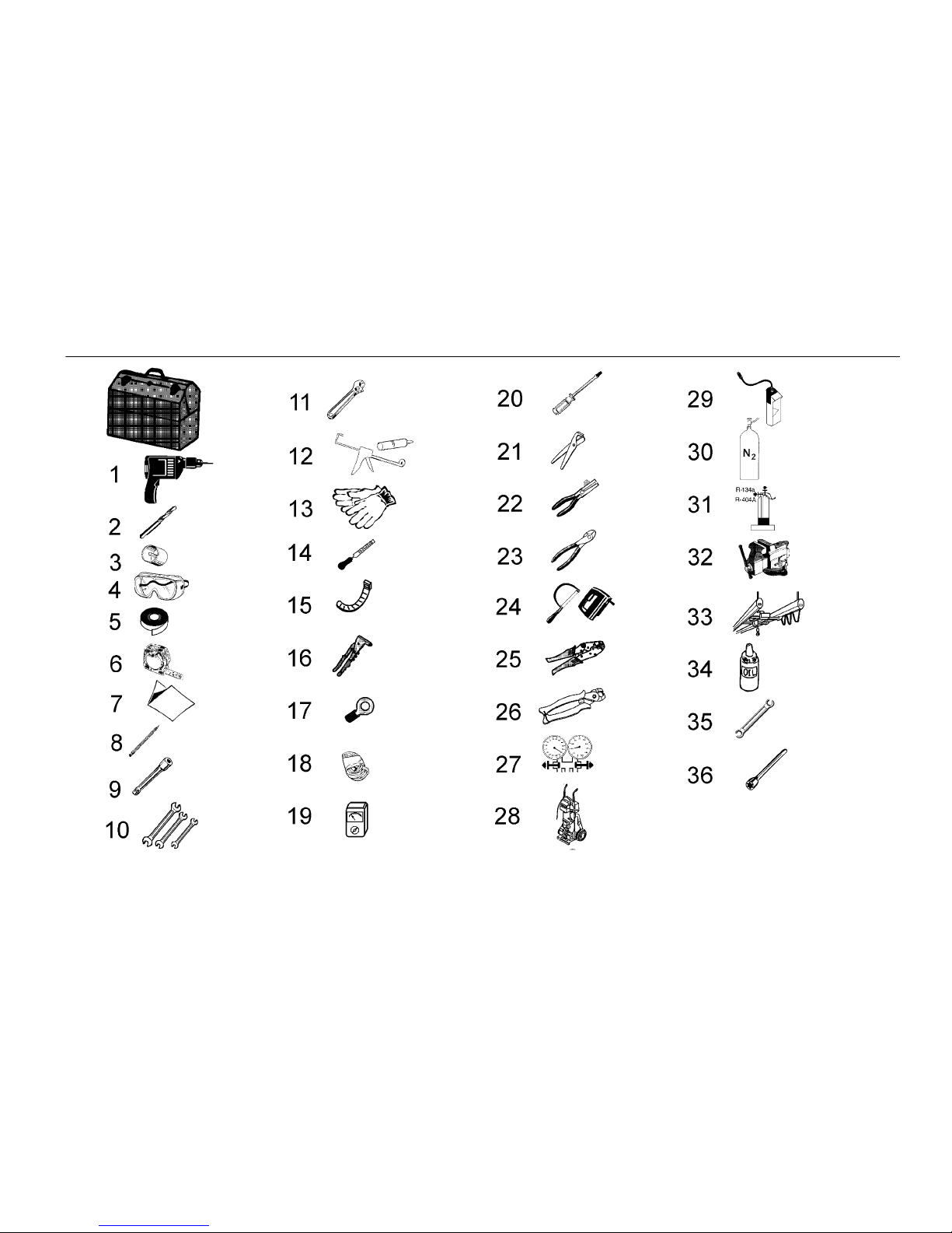
Required Tools
1. Electric drill
2. Set of drill bits
3. Set of glass-shaped cutters
4. Protective goggles
5. Adhesive tape
6. Measuring tape
7. Drilling template
8. Pencil
9. Socket wrenches
10. Fixed wrenches
11. Monkey wrench
12. Silicone
13. Protective gloves
14. File
15. Plastic flanges
16. Riveter
17. Electric connectors
18. Electrical wire
19. Voltmeter
20. Set of screwdrivers
21. Hose cutters
22. Wire strippers
23. Wire cutters
24. Electric and hand saws
25. Electrical terminal press
26. Pincers for hose clips
27. Gauge manifold
28. Vacuum pump
29. Leak detector
30. Nitrogen cylinder
31. Refrigerant cylinders
32. Table-mounted vice
33. Crane or hoist
34. TK refrigerant oil
35. Open Y wrench
36. Torx Tube Wrench
Page 9
9
Required Tools
Page 10
10
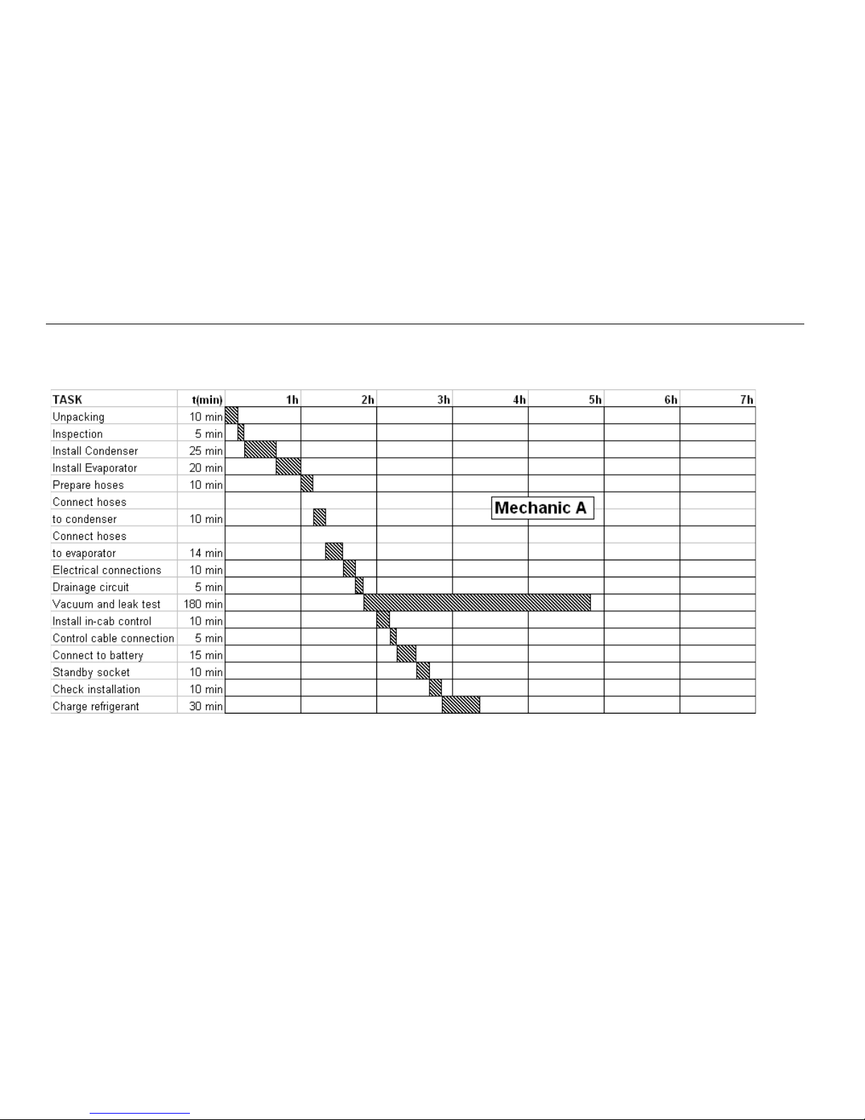
Operating Method
The operations indicated in this manual should be carried out by a mechanic in the exact sequence in which they are presented in the manual.
Page 11

11
Unpacking and Inspecting the Unit
Unpacking the Unit
1. Open the packaging.
2. Find the unit documentation.
3. Verify that the packaging contains all the accessories indicated on the
list attached with the documentation.
4. Check that the hose length is correct before starting the installation.
Checking can be carried out by consulting the “Packing List” included
with the unit documentation.
Inspecting the Unit
1. Open the condenser unit cover and ensure the following:
• Neither the cover nor the unit should show any shock damage
or imperfections.
• The condenser battery should be charged with helium gas.
• The voltage of all the electrical components is correct (12/24V).
2. Open the evaporator unit cover and make the following checks:
• Neither the cover nor the unit should show any shock damage
or imperfections.
• The evaporator battery should be charged with helium gas.
• The voltage of all the electrical components is correct (12/24V).
Page 12

12
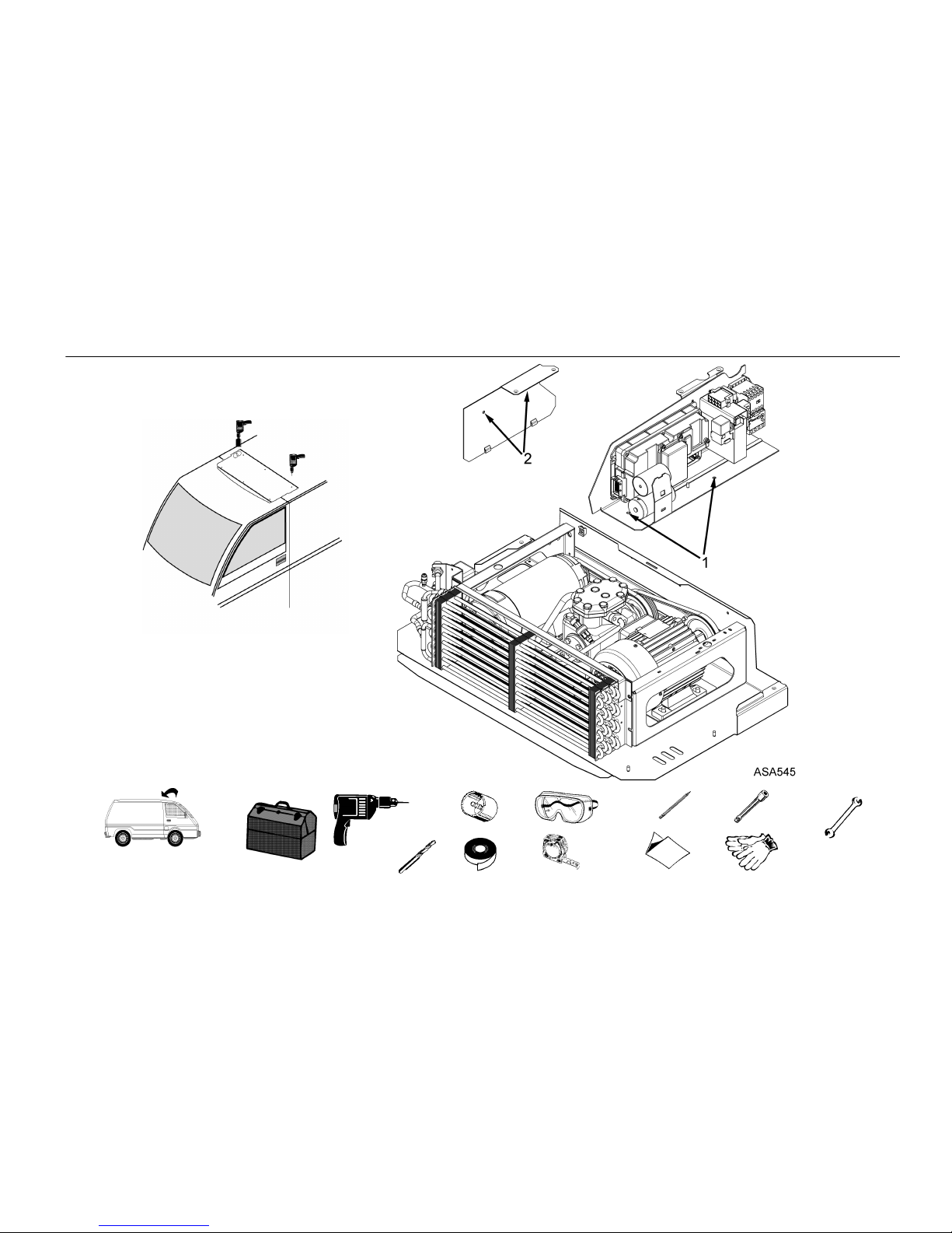
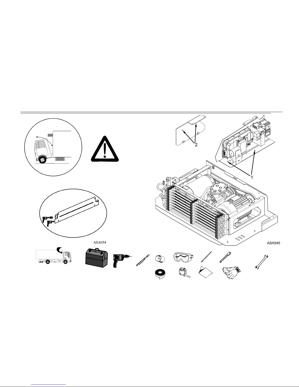
Installing the Condenser Unit (roof-mounted)
1. Fit the template according to the instructions given.
2. Mark the position of the drilled holes and openings. Avoid any possible
interference with electrical wires and parts of the vehicle chassis.
3. Drill the holes to hold the condenser unit in place (D 12) and the holes
for routing hoses (D 70).
4. Disassemble the canalizer.
5. Disassemble the electric box support plate on the unit,
by removing the two nuts, 1, securing the plate to the unit chassis.
6. Disassemble the canalizer support bracket plate by removing the two
hold-down bracket screws, 2, from the unit chassis.
Page 13
13
Installing the Condenser Unit (roof-mounted)
ASA052
T = 10 min.
Page 14

14
Installing the Condenser Unit (roof-mounted)
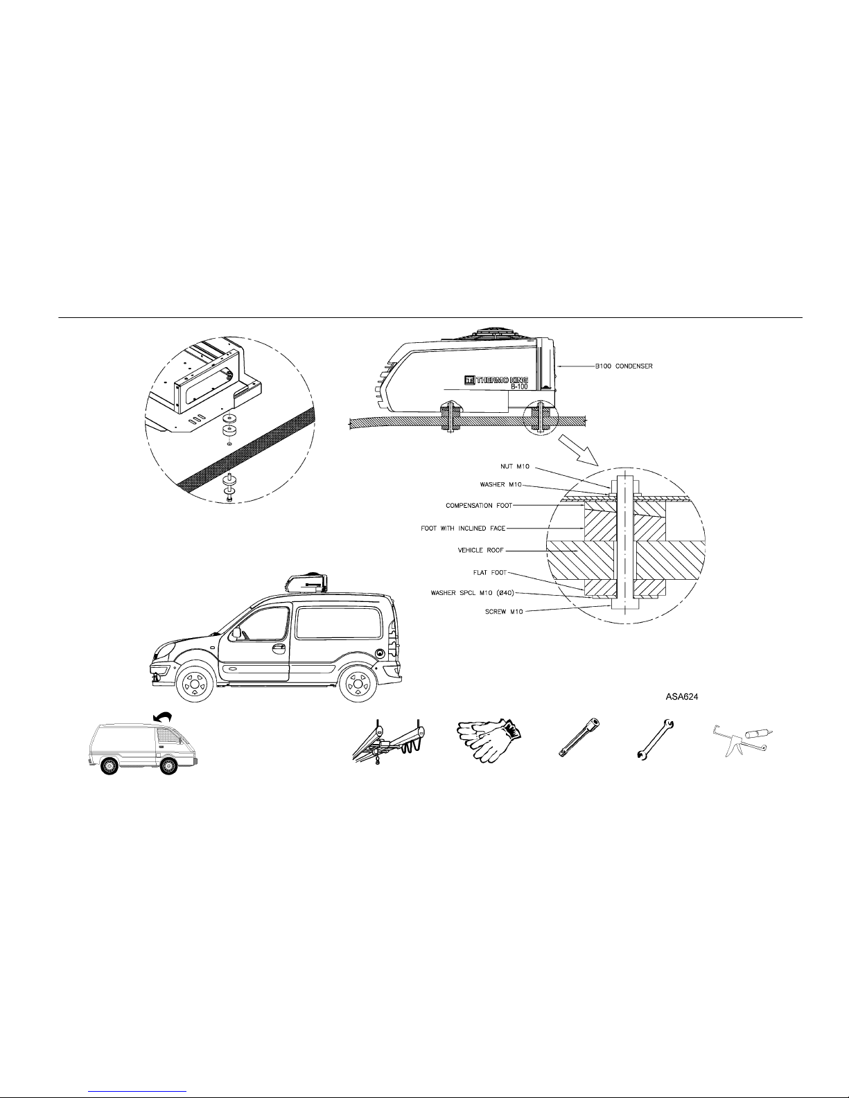
1. Fasten two strong straps attached to a crane to the unit. Lift the unit,
making sure that it remains in a horizontal position. If it does not,
change the position of the straps.
2. Place the unit on the roof of the vehicle. Remove the straps and the
crane.
3. Pass the 4 locks crews through the holes in the frame, placing a flat
washer onto each screw. Avoid direct contact between the unit and
the body by using rubber rings.
4. Fit the unit by attaching a nut and a washer onto each screw.
5. Reassemble the electrical box and canalizer support brackets.
6. Pass the hoses through the corresponding hole in the frame.
Page 15
15
Installing the Condenser Unit (roof-mounted)
T = 12 min.
Page 16

16
Installing the Condenser Unit (front-mounted)
1. Fit the template according to the instructions given.
2. Mark the position of the drilled holes and openings. Avoid any possible
interference with electrical wires and parts of the vehicle chassis.
3. Drill the holes to hold the condenser unit in place (D 12) and the holes
for routing hoses (D 70).
4. Disassemble the canalizer.
5. Disassemble the electric box support plate on the unit,
by removing the two nuts, 1, securing the plate to the unit chassis.
6. Disassemble the canalizer support bracket plate by removing the two
hold-down bracket screws, 2, from the unit chassis.
Page 17
17
Installing the Condenser Unit (front-mounted)
T = 10 min.
Page 18

18
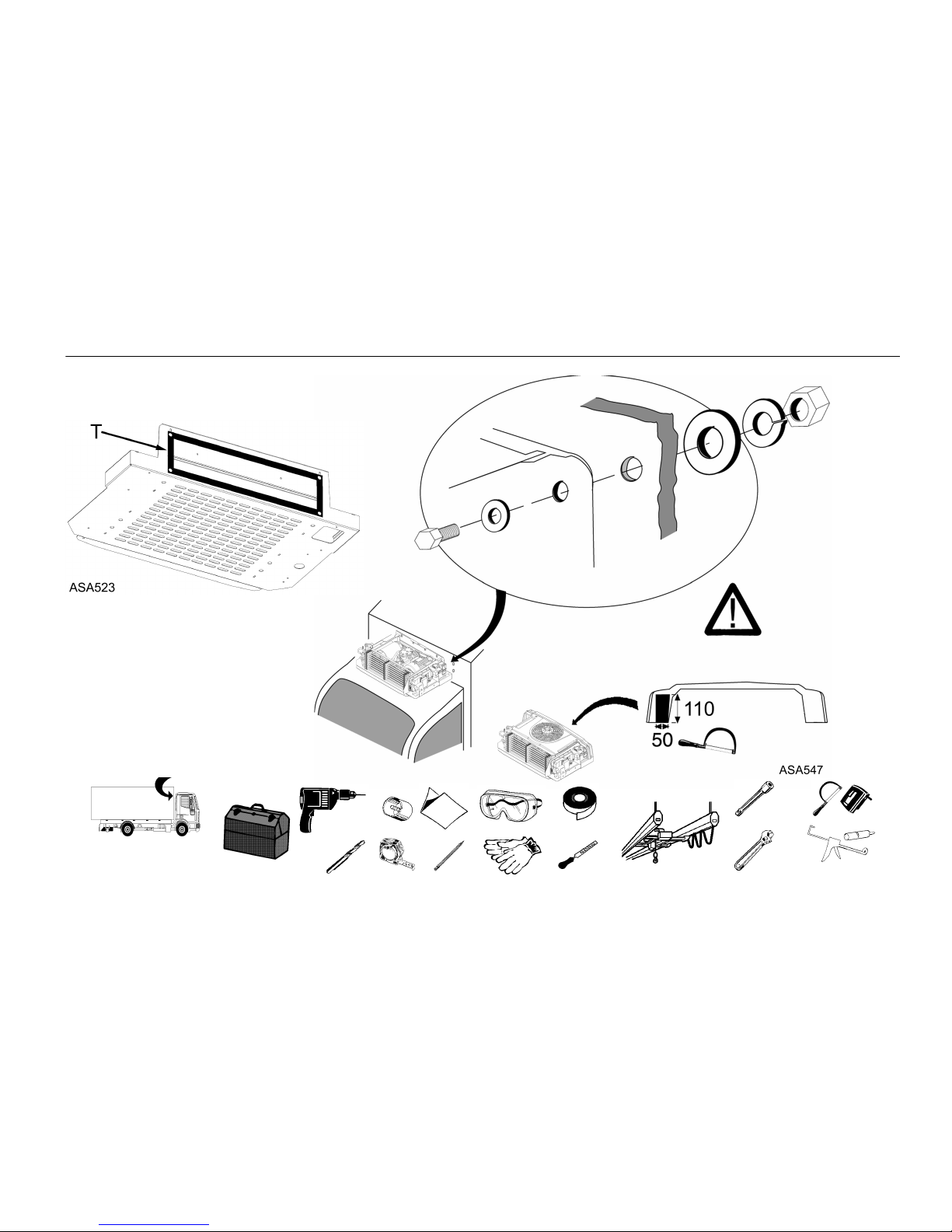
Installing the Condenser Unit (front-mounted)
1. Cut the routing guide C down as indicated in the illustration.
2. Fasten the adhesive tape T (supplied by Thermo King) to the rear of the
structure.
3. Fasten two strong straps attached to a crane to the unit. Lift the unit,
making sure that it remains in a horizontal position. If it does not,
change the position of the straps.
4. Pass the 4 locks crews through the holes of the structure and fix them
with a flat washer.
5. Fit the unit by twisting a nut and a Grower washer onto each screw.
Before tightening the screws completely, remove the straps and the
crane.
6. Reassemble the electrical box and canalizer support brackets.
7. Route the hoses through the correct hole in the structure.
Page 19
19
Installing the Condenser Unit (front-mounted)
C
T = 15 min.
Page 20

20
Installing the ES100 Evaporator Unit
1. Fit the template according to the instructions given.
2. Mark the position of the drilled holes. Avoid any possible interference
with electrical wires and parts of the vehicle chassis.
3. Drill blind holes to screw the evaporator unit in place. Screw in the
bolts and washers supplied for the ceiling. Do not tighten.
4. Cut the hole to route the moisture drain hose (diameter 22).
5. Install the unit on the ceiling supported by the bolts screwed in
previously.
6. Tighten the bolts.
Page 21

21
Installing the ES100 Evaporator Unit
T = 20 min.
Page 22

22
Preparing Refrigeration Hoses
Speedy Clip System
1. Cut the hose to the required length. Use the recommended hose cutters.
Do not use saws, knives or similar tools.
2. Pass two clips of appropriate diameter over the hose.
3. Lubricate the cylinder of the fitting to be inserted in the hose, using
Thermo King refrigerant oil.
4. Manually insert the fitting into the hose. The hose should touch the
projecting part of the fitting without going into it. Clean off excess oil.
5. Place the clamp for the clips into the fitting slot. The clamp is properly
positioned when it can rotate within the slot.
6. Place the clips in the clamp arm seats.
7. Close both clips using recommended pincers. Check that the clips are
properly positioned and closed (see drawings).
Page 23

23
Preparing Refrigeration Hoses
T = 10 min.
Page 24

24
Connecting Hoses to the Condenser Unit
1. Take the plugs off all the tubes.
2. Lubricate all refrigeration intakes with Thermo King refrigerant oil.
3. Place an O-ring on each refrigeration intake.
4. Check that the O-ring is properly positioned and connect each hose
using two fixed wrenches. The unconnected ends of the hoses must
be sealed.
Page 25

25
Connecting Hoses to the Condenser Unit
T = 10 min.
Page 26

26
Connecting Hoses to the ES100 Evaporator
1. Remove plugs from all tubing.
2. Lubricate all refrigeration intakes with Thermo King refrigerant oil.
3. Place an O-ring on each refrigeration intake.
4. Connect each hose using two fixed wrenches.
The O-ring should be properly positioned before the fitting is
screwed on.
5. Wrap the hoses with thermal insulation material (armaflex type) to
prevent water condensation.
6. Hermetically seal all holes where hoses and lock screws pass through.
Page 27

27
Connecting Hoses to the ES100 Evaporator
T = 14 min.
Page 28

28
Electrical Connections in the ES100 Evaporator
1. Pass the electrical hose and the return temperature sensor through as far
as the evaporator.
2. Connect the low pressure cutout, the defrost temperature thermostat,
the hot gas solenoid valve, and the temperature sensor.
3. Connect the fan.
4. Put the evaporator cover into position and secure using screws.
Page 29

29
Electrical Connections in the ES100 Evaporator
T = 10 min.
Page 30

30
Drain Circuit in the ES100 Evaporator
1. Cut the drain hose to the required length.
2. Connect the hose to the drain tube. Secure connections with plastic
flanges.
3. Route the hose through the drain hole and seal hermetically.
4. Check that the corresponding siphon or moisture trap is installed at the
end of each drain hose. If not, install it.
Page 31

31
Drain Circuit in the ES100 Evaporator
T = 5 min.
Page 32

32
Circuit Seal Test
1. Heat the box up to +20ºC/+70ºF using a ventilated radiator.
2. Connect the gauge manifold to the suction 1 and discharge 2 intakes
of the condenser unit.
3. Connect the central line of the gauge manifold to the vacuum pump.
Use recommended vacuum equipment. Before each use, check that
there are no leaks in the vacuum equipment, either in the pump itself or
in the hoses.
4. Open the gauge manifold and vacuum pump valves. Open all the
solenoid valves on the circuit.
5. Start the vacuum pump and maintain suction until it reaches
500 microns.
6. Once it reaches 500 microns, leave suction running for one hour.
7. Close the vacuum pump valve, switch off the pump, checking that the
gauge reading for the vacuum pump does not exceed 2000 microns in
the following 5 minutes. If it does exceed 2000 microns, follow the
procedure in the section: “In Case of Leaks”.
8. Start the vacuum pump again and open the vacuum valve. Leave the
pump running until it reaches 500 microns of pressure again.
9. Once it reaches 500 microns, close the vacuum pump valve and switch
off the pump. The unit is ready to be filled with refrigerant.
Page 33

33
Circuit Seal Test
Page 34

34
In Case of Leaks
1. Pressurize the circuit to 17 bar / 250 psig with nitrogen.
2. Identify the defective part (fitting, sleeve, line, hose, O-ring, etc.) and
replace it with a new part (if in doubt replace the entire joint).
Use the recommended leak detector.
3. Repeat the seal test from the beginning.
Page 35

35
In Case of Leaks
/ 250 psig
Page 36

36
Installing the In-Cab Control
1. Install the mounting bracket for the in-cab control box. Its design
allows the mounting bracket to be positioned in various places in the
cab interior. Find a location which is accessible and visible from the
driver’s seat, and which does not restrict the mobility or visibility of
either the driver or the vehicle’s instruments and levers.
2. Depending on the location chosen, the base should be mounted
following either Option A or Option B.
3. Mount the base of the mounting bracket in the chosen location. Use
screws (C), rubber mat (D) and metal plate (E), which are supplied by
Thermo King, as indicated in the drawing.
4. When placing the in-cab control box on the bracket, rest the in-cab
control box on the arm (F), and slide it to the right until the arm tab is
properly fitted to the in-cab control box frame.
5. The tilt of the in-cab control box’s front face may be altered by
loosening screw G.
6. Connect the data cable to connector H.
7. To remove the in-cab control box from the bracket, press the tab (I) and
slide to the left.
Page 37

37
Installing the In-Cab Control
1
3
T = 10 min.
Page 38

38
Optional Internal DIN Adaptor
1. Place the metal box (J) supplied in the housing designed for the radio.
Raise the tabs (M) sufficiently to fit the box into the housing.
2. Attach the control to the plastic bracket (L) using the 4 screws (K).
3. Connect the data cable to the control connector (H).
4. Insert the assembly formed by the control box and the plastic bracket
into the metal box, until the bracket tabs are properly fitted to the metal
box.
Page 39

39
Optional Internal DIN Adaptor
T = 5 min.
Page 40

40
Control Cable Connection
1. Pass cable 01 of the electrical hose through to the cab.
2. Locate the fuse box.
3. Connect wire 01 to the vehicle’s fused ignition circuit.
NOTE: Use a splice capable of supporting a 3A electrical current.
Page 41

41
Control Cable Connection
T = 5 min.
Page 42

42
Battery Connection
NOTE: If the vehicle is equipped with a battery disconnect switch, always
wire the unit after the switch. This allows power to the unit to be turned
off by the battery disconnect switch.
1. Pass electrical wires CHA (black), 01, BAT and 2 (brown) to the
battery.
2. Using the recommended tools, cut the wires to the proper length.
Do not coil or splice the excess wire.
3. Strip the wires and position the terminals supplied with the
recommended tools.
4. DISCONNECT THE CLAMP FROM THE BATTERY’S NEGATIVE
TERMINAL.
5. Connect wire 2 to one end of the fuse FP fuse holder (both supplied by
Thermo King) and connect the other end of the fuse holder to the
battery's positive pole. Install fuse FP (100A/12V or 60A/24V) in the
fuse holder. See note above.
6. Connect the *wire (wire between the battery and the vehicle starter
key) and the BAT wire to one end of the fuse F14 fuse holder (both
supplied by Thermo King), and connect the other end of the fuse holder
to the battery’s positive pole. Install fuse F14 (5A) in the fuse holder.
If F14 cannot be connected to the *wire, connect an additional fuse
(5A) between wire 01 and the vehicle starter key.
7. Connect the CHA wire to the clamp of the battery’s negative pole.
8. Reconnect the clamp of the battery’s negative terminal.
Page 43

43
Battery Connection
T = 15 min.
Page 44

44
Fitting the Power Supply Units with Electric Standby
1. Install the power supply housing in a protected and accessible location.
2. Route the wire from the unit to the power supply, using the clamps
provided.
3. Cut off the excess electrical wire. In order to avoid the coil effect, do
not roll up the excess electrical wire. Do not create splices in the
electrical wire.
4. Connect the electrical wire to the power supply, using recommended
tools.
WARNING: Always confirm the supply voltage matches the
voltage specifications of your particular unit prior to making any
electrical connections.
Page 45

45
Fitting the Power Supply Units with Electric Standby
T = 10 min.
Page 46

46
Door Switch Connection
1. Pass the electrical cable DSW1/CHW through to the door of the
compartment of the truck.
2. Connect the door switch to the two-way connector on cable
DSW1/CHW.
Page 47

47
Door Switch Connection
DSW1/CHW
T = 1 min.
Page 48

48
Installing the Deflector
1. Place the deflector on the condenser cover and align it with the two rear
holes.
2. Mark the two front holes on the condenser cover.
3. Remove the cover from the condenser and drill the two front holes.
4. Fit the deflector onto the cover, and secure it via two front holes using
the screws supplied by Thermo King.
5. Fit the cover-deflector assembly onto the condenser.
6. Secure the cover-deflector assembly to the condenser via the two rear
holes using the screws supplied by Thermo King.
Page 49

49
Installing the Deflector
T = 5 min.
Page 50

50
Installing the Hose Covers
1. Place (but do not fit for the moment) the elbow-shaped curved section,
aligning it so that the inside coincides with the rim of the hose outlet
hole.
2. Mark the left-hand baseline.
3. Mount and fit the straight section of the cover. To ensure the correct
curvature, the total width should be 446 mm.
4. If necessary, fit additional straight sections.
5. Cut the last straight section to the required length.
6. Secure the hoses using the clamps, choosing the best possible location.
7. Mount and fit the elbow-shaped curved section of the cover.
NOTE: The hoses may be connected before or after fitting the straight
section of the cover, depending on the particular characteristics of each
installation.
Page 51

51
Installing the Hose Covers
T = 12 min.
Page 52

52
In-Cab Control Box
DISPLAY, KEYS AND SYMBOLS
1. Display. It is always active and backlit except when the unit is
disconnected (no power) or when the unit is connected but has been
manually switched off from the In-cab Control Box. It normally
displays the return air temperature (of both load compartments in
bi-temperature units).
2. ON/OFF Key. This key is used to start/stop the unit. It is always lit
except when the unit is disconnected (no power), and thus acts as an
indicator of the presence of power in the unit.
3. Select Key. Selects prompt screens and information screens.
4. Up Key. Is used to increase the setpoint temperature.
5. Down Key. Is used to reduce the setpoint temperature.
6. Enter Key. Is used to enter a new command such as manual defrost,
etc.
7. Buzzer. It is energized when the vehicle battery and the electric power
supply are connected simultaneously. It is also energized if the doors
are opened while the refrigeration unit is running.
8. Cool Symbol (Thermometer with an arrow pointing downward). The
unit is cooling.
9. Heat Symbol (Thermometer with an arrow pointing upward). The unit
is heating.
10. ºC/ºF Symbol. Indicates whether the on-screen temperature reading is
in degrees Celsius (ºC) or degrees Fahrenheit (ºF).
11. Alarm Symbol. Indicates that there is an alarm in the system.
12. Maintenance Symbol. Warns of the need to carry out maintenance to
the unit.
13. Defrost Symbol. Indicates the unit is in Defrost Mode.
14. Electrical Symbol. Indicates that the unit is in Electric Standby.
15. Triangle Symbol. Indicates that the return air temperature of the
remote load compartment is outside the setpoint temperature range of
the remote compartment.
HOURMETER MENU
From the Standard Display press the SELECT key for 3 seconds to enter
the Hourmeter Menu, then use the SELECT key to display:
1. HC: Hours remaining to maintenance notice.
2. tH: The total amount of time the unit has been switched on protecting
the load.
3. CC: Battery Mode Compressor Hours.
4. EC: Electric Mode Compressor Hours.
5. Return to Standard Display.
INFORMATION MENU
From the Standard Display press the ENTER plus the UP key during 3
seconds to enter the Information Menu, which scrolls automatically
through the following:
1. Display test (all symbols on).
2. Software version.
3. Refrigerant type.
4. bat: current battery voltage (value in volts, decimal).
5. HP: current pressure.
6. Number of Compartments/Unit type.
7. Return to Standard Display.
Page 53

53
In-Cab Control Box
INSTALLATION MENU
From the Standard Display press the ENTER plus the DOWN key for 3 seconds to enter the Installation Menu: the first parameter will be displayed, the value
in the large digits and its name in the small digits. To modify the parameter value press the ENTER key, the value will flash, press the UP or DOWN key to
modify the value and confirm by pressing the ENTER key again. To scroll through the menu press the UP or DOWN keys.
NOTE: Some Direct Smart Reefer versions show the setpoint temperature (SP) as the first parameter in the Installation Menu.
NAME DESCRIPTION DEFAULT MIN MAX
diF Set Points Differential
Once the setpoint temperature has been reached, and while the temperature remains between diF ºC/ºF above or below the setpoint, there is
no demand for transfer of heat or cold, and the unit remains in null mode. Increments of 1º.
3 1 5
SSC Soft Start Cycles (ON/OFF)
Programmable soft start for the road compressor clutch.
OFF OFF ON
dit Defrost Initiation Timer (Minutes)
Increments of 30 minutes.
On time out the unit will switch from cool to the appropriate defrost mode. The timer will count all the time the system is in any cool mode. The
timer will be reset when a defrost starts.
When the value is set at 0, is the test position: the defrost will begin in 15 seconds.
240 30 480
dtt Defrost Termination Timer (Minutes)
Increments of 5 minutes.
Timer will count from defrost mode initiation. Timer will reset after a temperature defrost termination or timer time out. On time out the unit will
switch from defrost to null mode.
When the value is set at 0, is the test position: the defrost will stop in 15 seconds.
30 5 50
EFc Evaporator Fans Constant Blow
on: evaporator fans stays on also during null mode.
off: evaporator fans cycles on and off with the regulators.
OFF OFF ON
dAL Out Of Range Alarm
Progammable from 1º up to 10º or off (0). When the difference between the return air temperature and the set point exceeds the on-screen
return air temperature reading flashes.
0 0 10
HC Hour Counter Initial Value For Maintenance Purposes
(Tens of hours, e.g. 150=1500 hours), programmable from 1000 up to 5000, 500 steps.
150 0 500
Page 54

54
In-Cab Control Box
NAME DESCRIPTION DEFAULT MIN MAX
dSP
Doors Switches Presence/polarity
0: normally closed, 1: normally open, 2: not present.
1 0 2
bE
Buzzer Enable
0: not enabled, 1: enabled, 2: enabled also when keys are pressed, 3: enabled only when keys are pressed.
2 0 3
tu
Thermostat Units
C: temperature visualization in ºC, F: temperature visualization in ºF.
C C F
Pu Pressure Units
b: pressure visualization in bar, P: pressure visualization in psig
P b P
Page 55

55
Checking the Installation
• All holes should be sealed with silicone or foam.
• Check with a sheet of paper that the fans blow in the right direction.
• The drain circuit should be slanted on all evaporators and the moisture trap should be installed.
• The hole should be located at the expansion valve on all evaporators.
• The temperature sensor should be connected on all evaporators.
• The in-cab control box should be located in a spot that it is accessible and visible from the driver’s position.
• The contact draw should be made.
• Hoses should not be taut (they should be able to absorb vibrations and be shortened in case of leaks).
• Hoses should not rub against moving parts, sharp parts, or parts that can reach high temperatures.
• The unit should be connected to the battery.
• The seal test should have been carried out.
Page 56

56
Charging the Circuit
1. Connect the gauge manifold to the suction and discharge line intakes of
the condenser unit.
2. Connect the refrigerant bottle to the gauge manifold and place it on a
set of scales.
3. Open the refrigerant bottle valve and drain the gauge fitting line.
4. Keep the low pressure side valve of the gauge manifold closed. Open
the high pressure side valve.
5. Add refrigerant until reaching approximately 0.95 kg/2.1 lb of R-134a.
6. Close the refrigerant bottle valve and the high side valve of the gauge
manifold.
7. Start the vehicle engine running at around 1000 rpm and switch on the
unit.
8. Set the unit thermostat at 0ºC/32ºF (see operating manual).
9. Run the unit until it reaches a temperature close to that indicated, and a
high circuit pressure of 12.5 bar / 180 psig for R-134a. Partially
close the air intake to the condenser if necessary.
10. Open the low side valve of the gauge manifold and the refrigerant
bottle valve, and add refrigerant slowly until no bubbles can be seen
through the liquid sight glass.
11. Close the refrigerant bottle and gauge manifold valves.
12. Leave the unit running for 15 minutes.
13. Only if you are installing a unit without electrical standby, turn off the
unit, stop the vehicle and remove the gauge manifold.
Page 57

57
Charging the Circuit
Page 58

58
Outline Drawings
Page 59

59
Outline Drawings
Page 60

60
Outline Drawings
Page 61

61
Page 62

62
Page 63

63
Page 64

64
 Loading...