

Thermo King 098223, 098580, 098218, 098581, 098582 Maintenance Manual
...
Additional text information
Maintenance Manual
SB-210+
SB-210+
MAGNUM +
Additional text information
Additional text information
to be placed here
to be placed here
TK 60275-4-MM (Rev. 3, 08/15)
TK 5XXXX-X-PL
TK 5XXXX-X-PL


MAGNUM+
TK 60275-4-MM (Rev. 3, 08/15)
Copyright© 2012 Ingersoll Rand - EMEIA Printed in Ireland

The maintenance information in this manual covers unit models:
Base Units
MAGNUM+ 098212 098216 098218 098203
098219 098223 098580
098581 098582 098583
098585 098586 098587
098588 098589 098590
098591 098592 098593
098594
For further information, refer to:
Parts Manuals
MAGNUM Parts List TK 54356
Operation, Diagnosis and Refrigeration Maintenance Manuals
Diagnosing Thermo King Container Refrigeration Systems TK 41166
Electrostatic Discharge (ESD) Training Guide TK 40282
Evacuation Station Operation and Field Application TK 40612
Tool Catalog TK 5955
The information in this manual is provided to assist owners, operators and service people in the proper
upkeep and maintenance of Thermo King units.
Revision History
Rev. 3 – TK 60275-4-MM (Rev. 3, 08/15) Add information per Service and Software Bulletins
since previous revision.
This manual is published strictly for informational purposes. The informa tion so provided sh ould
not be considered as all-inclusive or covering all contingencies. Thermo King Corporation
should be consulted if further information is required.
Sale of product shown in this manual is subject to Thermo King’s terms and conditions.
This includes, but not limited to, the Thermo King Limited Express Warranty. Such terms
and conditions are available upon request. Thermo King’s warranty will not apply to any
equipment which has been “so repaired or altered outside the manufacturer’s plants as,
in the manufacturer’s judgment, to effect its stability.”
No warranties, express or implied, are made regarding the information,
recommendations, and descriptions contained herein. This includes warranties of
fitness for a particular purpose or merchantability, or warranties arising from course of
dealing or usage of trade. The manufacturer is not responsible and will not be held liable
in contract or in tort (including negligence) for any special, indirect or consequential
damages. This includes injury or damage caused to vehicles, contents or persons, by
reason of the installation of any Thermo King product or its mechanical failure.
2
Recover Refrigerant
At Thermo King, we recognize the need to preserve the environment
and limit the potential harm to the ozone layer that can result from
allowing refrigerant to escape into the atmosphere.
We strictly adhere to a policy that promotes the recovery and limits
the loss of refrigerant into the atmosphere.
In addition, service personnel must be aware of Federal regulations
concerning the use of refrigerants and the certification of technicians.
For additional information on regulations and technician certification
programs, contact your local Thermo King dealer.
R-404A
WARNING: Use only Polyol Ester-based refrigeration compressor oil in
R-404A. See Thermo King Parts Manual for part number.
Do not mix Polyol Ester and standard synthetic compressor oils. Keep Polyol
Ester compressor oil in tightly sealed containers. If Polyol Ester oil becomes
contaminated with moisture or standard oils, dispose of properly–DO NOT USE.
When servicing Thermo King R-404A unit, use only those service tools certified
for and dedicated to R-404A refrigerant and Polyol Ester compressor oils.
Residual non-HFX refrigerants or oils will contaminate R-404A systems.
3

Table of Contents
Safety Instructions . . . . . . . . . . . . . . . . . . . . . . . . . . . . . . . . . . . . . . . . . . . . . . . . . . . . . . . . . . . . . . . . . . . . . . .9
General Precautions . . . . . . . . . . . . . . . . . . . . . . . . . . . . . . . . . . . . . . . . . . . . . . . . . . . . . . . . . . . . . . . . . . . . . . .9
Refrigerant Oil Precautions . . . . . . . . . . . . . . . . . . . . . . . . . . . . . . . . . . . . . . . . . . . . . . . . . . . . . . . . . . . . . . . . . .9
Electrical Precautions . . . . . . . . . . . . . . . . . . . . . . . . . . . . . . . . . . . . . . . . . . . . . . . . . . . . . . . . . . . . . . . . . . . . .10
Precautions . . . . . . . . . . . . . . . . . . . . . . . . . . . . . . . . . . . . . . . . . . . . . . . . . . . . . . . . . . . . . . . . . . . . . . . . . .10
First Aid . . . . . . . . . . . . . . . . . . . . . . . . . . . . . . . . . . . . . . . . . . . . . . . . . . . . . . . . . . . . . . . . . . . . . . . . . . . . .10
Low Voltage . . . . . . . . . . . . . . . . . . . . . . . . . . . . . . . . . . . . . . . . . . . . . . . . . . . . . . . . . . . . . . . . . . . . . . . . .11
Electrostatic Discharge Precautions . . . . . . . . . . . . . . . . . . . . . . . . . . . . . . . . . . . . . . . . . . . . . . . . . . . . . . . . . .11
Electrostatic Discharge and the Controller . . . . . . . . . . . . . . . . . . . . . . . . . . . . . . . . . . . . . . . . . . . . . . . . . .11
Welding of Units or Containers . . . . . . . . . . . . . . . . . . . . . . . . . . . . . . . . . . . . . . . . . . . . . . . . . . . . . . . . . . .12
Removing Refrigerant Properly . . . . . . . . . . . . . . . . . . . . . . . . . . . . . . . . . . . . . . . . . . . . . . . . . . . . . . . . . . . . . .12
Identifying Unit Safety and Warning Decals . . . . . . . . . . . . . . . . . . . . . . . . . . . . . . . . . . . . . . . . . . . . . . . . . . . .14
Locating Serial Numbers . . . . . . . . . . . . . . . . . . . . . . . . . . . . . . . . . . . . . . . . . . . . . . . . . . . . . . . . . . . . . . . . . . .14
Component Serial Number Identification . . . . . . . . . . . . . . . . . . . . . . . . . . . . . . . . . . . . . . . . . . . . . . . . . . .14
Service Guide . . . . . . . . . . . . . . . . . . . . . . . . . . . . . . . . . . . . . . . . . . . . . . . . . . . . . . . . . . . . . . . . . . . . . . . . . . .15
Service Guide . . . . . . . . . . . . . . . . . . . . . . . . . . . . . . . . . . . . . . . . . . . . . . . . . . . . . . . . . . . . . . . . . . . . . . . . . . .15
Specifications . . . . . . . . . . . . . . . . . . . . . . . . . . . . . . . . . . . . . . . . . . . . . . . . . . . . . . . . . . . . . . . . . . . . . . . . . .16
Evaporator Airflow Specifications . . . . . . . . . . . . . . . . . . . . . . . . . . . . . . . . . . . . . . . . . . . . . . . . . . . . . . . . . . . .16
Electrical System Specifications . . . . . . . . . . . . . . . . . . . . . . . . . . . . . . . . . . . . . . . . . . . . . . . . . . . . . . . . . . . . .17
Refrigeration System Specifications . . . . . . . . . . . . . . . . . . . . . . . . . . . . . . . . . . . . . . . . . . . . . . . . . . . . . . . . . .18
Unit Description, Features & Options . . . . . . . . . . . . . . . . . . . . . . . . . . . . . . . . . . . . . . . . . . . . . . . . . . . . . . .22
Introduction . . . . . . . . . . . . . . . . . . . . . . . . . . . . . . . . . . . . . . . . . . . . . . . . . . . . . . . . . . . . . . . . . . . . . . . . . . . . .22
General Description . . . . . . . . . . . . . . . . . . . . . . . . . . . . . . . . . . . . . . . . . . . . . . . . . . . . . . . . . . . . . . . . . . .22
Scroll Compressor . . . . . . . . . . . . . . . . . . . . . . . . . . . . . . . . . . . . . . . . . . . . . . . . . . . . . . . . . . . . . . . . . . . . . . . .23
MP-4000 Controller . . . . . . . . . . . . . . . . . . . . . . . . . . . . . . . . . . . . . . . . . . . . . . . . . . . . . . . . . . . . . . . . . . . . . . .24
Power Module Fuses . . . . . . . . . . . . . . . . . . . . . . . . . . . . . . . . . . . . . . . . . . . . . . . . . . . . . . . . . . . . . . . . . .24
Compressor Digital Control Valve . . . . . . . . . . . . . . . . . . . . . . . . . . . . . . . . . . . . . . . . . . . . . . . . . . . . . . . . . . . .25
Economizer Heat Exchange System . . . . . . . . . . . . . . . . . . . . . . . . . . . . . . . . . . . . . . . . . . . . . . . . . . . . . . . . . .25
Temperature Sensors . . . . . . . . . . . . . . . . . . . . . . . . . . . . . . . . . . . . . . . . . . . . . . . . . . . . . . . . . . . . . . . . . . . . .25
Fresh Air Exchange System . . . . . . . . . . . . . . . . . . . . . . . . . . . . . . . . . . . . . . . . . . . . . . . . . . . . . . . . . . . . . . . .26
Receiver Tank Sight Glass . . . . . . . . . . . . . . . . . . . . . . . . . . . . . . . . . . . . . . . . . . . . . . . . . . . . . . . . . . . . . . . . .26
Evaporator Fans . . . . . . . . . . . . . . . . . . . . . . . . . . . . . . . . . . . . . . . . . . . . . . . . . . . . . . . . . . . . . . . . . . . . . . . . .26
Condenser Fan Control . . . . . . . . . . . . . . . . . . . . . . . . . . . . . . . . . . . . . . . . . . . . . . . . . . . . . . . . . . . . . . . . . . . .27
USDA Cold Treatment Temperature Recording (standard) . . . . . . . . . . . . . . . . . . . . . . . . . . . . . . . . . . . . .27
Unit Options . . . . . . . . . . . . . . . . . . . . . . . . . . . . . . . . . . . . . . . . . . . . . . . . . . . . . . . . . . . . . . . . . . . . . . . . . . . . .28
Electronic Chart Recorder (Optional) . . . . . . . . . . . . . . . . . . . . . . . . . . . . . . . . . . . . . . . . . . . . . . . . . . . . . .29
Remote Monitoring Modem (RMM, RMM+) (Optional) . . . . . . . . . . . . . . . . . . . . . . . . . . . . . . . . . . . . . . . . .29
Suction and Discharge Pressure Sensors (Optional) . . . . . . . . . . . . . . . . . . . . . . . . . . . . . . . . . . . . . . . . . .29
Water-Cooled Condenser/Receiver Tank (Optional) . . . . . . . . . . . . . . . . . . . . . . . . . . . . . . . . . . . . . . . . . .29
Air Ventilation Logging (AVL - Optional) . . . . . . . . . . . . . . . . . . . . . . . . . . . . . . . . . . . . . . . . . . . . . . . . . . . .30
Advanced Fresh Air Management (AFAM) System (Optional) . . . . . . . . . . . . . . . . . . . . . . . . . . . . . . . . . . .30
Advanced Fresh Air Management Plus (AFAM+) System (Optional) . . . . . . . . . . . . . . . . . . . . . . . . . . . . . .31
Controller Description . . . . . . . . . . . . . . . . . . . . . . . . . . . . . . . . . . . . . . . . . . . . . . . . . . . . . . . . . . . . . . . . . . . .37
Controller Description . . . . . . . . . . . . . . . . . . . . . . . . . . . . . . . . . . . . . . . . . . . . . . . . . . . . . . . . . . . . . . . . . . . . .37
Controller Back-up Battery . . . . . . . . . . . . . . . . . . . . . . . . . . . . . . . . . . . . . . . . . . . . . . . . . . . . . . . . . . . . . .37
Controller Input and Output Signals . . . . . . . . . . . . . . . . . . . . . . . . . . . . . . . . . . . . . . . . . . . . . . . . . . . . . . .37
Standard Display . . . . . . . . . . . . . . . . . . . . . . . . . . . . . . . . . . . . . . . . . . . . . . . . . . . . . . . . . . . . . . . . . . . . . . . . .39
Idle Screen . . . . . . . . . . . . . . . . . . . . . . . . . . . . . . . . . . . . . . . . . . . . . . . . . . . . . . . . . . . . . . . . . . . . . . . . . .39
Glossary of Mode Descriptions . . . . . . . . . . . . . . . . . . . . . . . . . . . . . . . . . . . . . . . . . . . . . . . . . . . . . . . . . . .41
Function Keys . . . . . . . . . . . . . . . . . . . . . . . . . . . . . . . . . . . . . . . . . . . . . . . . . . . . . . . . . . . . . . . . . . . . . . . . . . .42
Three Special Function Keys . . . . . . . . . . . . . . . . . . . . . . . . . . . . . . . . . . . . . . . . . . . . . . . . . . . . . . . . . . . . . . . .43
MP-4000 Software . . . . . . . . . . . . . . . . . . . . . . . . . . . . . . . . . . . . . . . . . . . . . . . . . . . . . . . . . . . . . . . . . . . . . . . .44
Software Version 2.3.4 100927 . . . . . . . . . . . . . . . . . . . . . . . . . . . . . . . . . . . . . . . . . . . . . . . . . . . .
Software Version 2.3.6 110301
Software Version 2.3.7.0 110608 . . . . . . . . . . . . . . . . . . . . . . . . . . . . . . . . . . . . . . . . . . . . . . . . . . . . . . . . .46
Software Version 2.3.8.0 110628 . . . . . . . . . . . . . . . . . . . . . . . . . . . . . . . . . . . . . . . . . . . . . . . . . . . . . . . . .47
Software Version 2.4.0.0 111220 . . . . . . . . . . . . . . . . . . . . . . . . . . . . . . . . . . . . . . . . . . . . . . . . . . . . . . . . .48
. . . . . . . . . . . . . . . . . . . . . . . . . . . . . . . . . . . . . . . . . . . . . . . . . . . . . . . . . . .45
. . . . . . .44
4

Table of Contents
Software Version 2.4.2.0 120313 . . . . . . . . . . . . . . . . . . . . . . . . . . . . . . . . . . . . . . . . . . . . . . . . . . . . . . . . . 48
Software Version 2.4.3.0 120628 . . . . . . . . . . . . . . . . . . . . . . . . . . . . . . . . . . . . . . . . . . . . . . . . . . . . . . . . . 49
Software Version 2.5.0.0 121121 . . . . . . . . . . . . . . . . . . . . . . . . . . . . . . . . . . . . . . . . . . . . . . . . . . . . . . . . . 50
Software Version 2.5.1.0 130213 . . . . . . . . . . . . . . . . . . . . . . . . . . . . . . . . . . . . . . . . . . . . . . . . . . . . . . . . . 51
Software Version 2.5.3.0 130424 . . . . . . . . . . . . . . . . . . . . . . . . . . . . . . . . . . . . . . . . . . . . . . . . . . . . . . . . . 51
Software Version 3.1.0.0 140612 . . . . . . . . . . . . . . . . . . . . . . . . . . . . . . . . . . . . . . . . . . . . . . . . . . . . . . . . . 52
Software Version 3.2.0.0 140822 . . . . . . . . . . . . . . . . . . . . . . . . . . . . . . . . . . . . . . . . . . . . . . . . . . . . . . . . . 53
Operating Instructions . . . . . . . . . . . . . . . . . . . . . . . . . . . . . . . . . . . . . . . . . . . . . . . . . . . . . . . . . . . . . . . . . . . 54
Function Keys . . . . . . . . . . . . . . . . . . . . . . . . . . . . . . . . . . . . . . . . . . . . . . . . . . . . . . . . . . . . . . . . . . . . . . . . . . . 54
Unit On/Off Key . . . . . . . . . . . . . . . . . . . . . . . . . . . . . . . . . . . . . . . . . . . . . . . . . . . . . . . . . . . . . . . . . . . . . . 55
Sequence Of Operation . . . . . . . . . . . . . . . . . . . . . . . . . . . . . . . . . . . . . . . . . . . . . . . . . . . . . . . . . . . . . . . . . . . 55
Unit Start-up . . . . . . . . . . . . . . . . . . . . . . . . . . . . . . . . . . . . . . . . . . . . . . . . . . . . . . . . . . . . . . . . . . . . . . . . . 55
Initiating a Manual Defrost . . . . . . . . . . . . . . . . . . . . . . . . . . . . . . . . . . . . . . . . . . . . . . . . . . . . . . . . . . . . . . 55
PTI . . . . . . . . . . . . . . . . . . . . . . . . . . . . . . . . . . . . . . . . . . . . . . . . . . . . . . . . . . . . . . . . . . . . . . . . . . . . . . . . 56
Viewing Alarms/Warnings . . . . . . . . . . . . . . . . . . . . . . . . . . . . . . . . . . . . . . . . . . . . . . . . . . . . . . . . . . . . . . . 57
Display Alternate Fahrenheit (F) or Celsius (C) Temperatures . . . . . . . . . . . . . . . . . . . . . . . . . . . . . . . . . .57
Changing Setpoint . . . . . . . . . . . . . . . . . . . . . . . . . . . . . . . . . . . . . . . . . . . . . . . . . . . . . . . . . . . . . . . . . . . . 57
Main Menu . . . . . . . . . . . . . . . . . . . . . . . . . . . . . . . . . . . . . . . . . . . . . . . . . . . . . . . . . . . . . . . . . . . . . . . . . . 57
Controller Back-up Battery . . . . . . . . . . . . . . . . . . . . . . . . . . . . . . . . . . . . . . . . . . . . . . . . . . . . . . . . . . . . . . 58
Controller Lockup Issue . . . . . . . . . . . . . . . . . . . . . . . . . . . . . . . . . . . . . . . . . . . . . . . . . . . . . . . . . . . . . . . . . . . 58
Emergency Run Mode . . . . . . . . . . . . . . . . . . . . . . . . . . . . . . . . . . . . . . . . . . . . . . . . . . . . . . . . . . . . . . . . . . . . 59
Rotation Check . . . . . . . . . . . . . . . . . . . . . . . . . . . . . . . . . . . . . . . . . . . . . . . . . . . . . . . . . . . . . . . . . . . . . . . 59
FULL COOL Mode . . . . . . . . . . . . . . . . . . . . . . . . . . . . . . . . . . . . . . . . . . . . . . . . . . . . . . . . . . . . . . . . . . . . 61
DEFROST Mode . . . . . . . . . . . . . . . . . . . . . . . . . . . . . . . . . . . . . . . . . . . . . . . . . . . . . . . . . . . . . . . . . . . . . 62
High or Low Speed Fans Only . . . . . . . . . . . . . . . . . . . . . . . . . . . . . . . . . . . . . . . . . . . . . . . . . . . . . . . . . . . 62
Navigating the Controller Operating Menu . . . . . . . . . . . . . . . . . . . . . . . . . . . . . . . . . . . . . . . . . . . . . . . . . . . 64
Navigating the Controller Operating Menu . . . . . . . . . . . . . . . . . . . . . . . . . . . . . . . . . . . . . . . . . . . . . . . . . . . . . 64
Icon Menu . . . . . . . . . . . . . . . . . . . . . . . . . . . . . . . . . . . . . . . . . . . . . . . . . . . . . . . . . . . . . . . . . . . . . . . . . . . 65
Menu Scrolling Keys . . . . . . . . . . . . . . . . . . . . . . . . . . . . . . . . . . . . . . . . . . . . . . . . . . . . . . . . . . . . . . . . . . . 66
Changing Screen Contrast . . . . . . . . . . . . . . . . . . . . . . . . . . . . . . . . . . . . . . . . . . . . . . . . . . . . . . . . . . . . . . 67
Main Menu . . . . . . . . . . . . . . . . . . . . . . . . . . . . . . . . . . . . . . . . . . . . . . . . . . . . . . . . . . . . . . . . . . . . . . . . . . . . . 68
Main Menu . . . . . . . . . . . . . . . . . . . . . . . . . . . . . . . . . . . . . . . . . . . . . . . . . . . . . . . . . . . . . . . . . . . . . . . . . . . . . 68
Data/Values Menu . . . . . . . . . . . . . . . . . . . . . . . . . . . . . . . . . . . . . . . . . . . . . . . . . . . . . . . . . . . . . . . . . . . . . . . 68
MP4000 . . . . . . . . . . . . . . . . . . . . . . . . . . . . . . . . . . . . . . . . . . . . . . . . . . . . . . . . . . . . . . . . . . . . . . . . . . . . 68
Data/Values . . . . . . . . . . . . . . . . . . . . . . . . . . . . . . . . . . . . . . . . . . . . . . . . . . . . . . . . . . . . . . . . . . . . . . . . . 68
Setpoint/Control Menu . . . . . . . . . . . . . . . . . . . . . . . . . . . . . . . . . . . . . . . . . . . . . . . . . . . . . . . . . . . . . . . . . . . . 69
Cold Treatment (CT) . . . . . . . . . . . . . . . . . . . . . . . . . . . . . . . . . . . . . . . . . . . . . . . . . . . . . . . . . . . . . . . . . . . 70
Multiple Temperature Set (MTS) . . . . . . . . . . . . . . . . . . . . . . . . . . . . . . . . . . . . . . . . . . . . . . . . . . . . . . . . . 70
OPTISET . . . . . . . . . . . . . . . . . . . . . . . . . . . . . . . . . . . . . . . . . . . . . . . . . . . . . . . . . . . . . . . . . . . . . . . . . . . 71
Temperature Setpoint . . . . . . . . . . . . . . . . . . . . . . . . . . . . . . . . . . . . . . . . . . . . . . . . . . . . . . . . . . . . . . . . . . 71
Controlling Mode . . . . . . . . . . . . . . . . . . . . . . . . . . . . . . . . . . . . . . . . . . . . . . . . . . . . . . . . . . . . . . . . . . . . . 72
Pull Down Selection . . . . . . . . . . . . . . . . . . . . . . . . . . . . . . . . . . . . . . . . . . . . . . . . . . . . . . . . . . . . . . . . . . . 72
Watercool . . . . . . . . . . . . . . . . . . . . . . . . . . . . . . . . . . . . . . . . . . . . . . . . . . . . . . . . . . . . . . . . . . . . . . . . . . . 73
Humidity Control . . . . . . . . . . . . . . . . . . . . . . . . . . . . . . . . . . . . . . . . . . . . . . . . . . . . . . . . . . . . . . . . . . . . . . 73
Humidity Setpoint . . . . . . . . . . . . . . . . . . . . . . . . . . . . . . . . . . . . . . . . . . . . . . . . . . . . . . . . . . . . . . . . . . . . . 74
AVL (Air Ventilation Logging) . . . . . . . . . . . . . . . . . . . . . . . . . . . . . . . . . . . . . . . . . . . . . . . . . . . . . . . . . . . . 74
Fresh Air Vent Man - AFAM Mode . . . . . . . . . . . . . . . . . . . . . . . . . . . . . . . . . . . . . . . . . . . . . . . . . . . . . . . . 75
Fresh Air Vent Man - AFAM+ Mode . . . . . . . . . . . . . . . . . . . . . . . . . . . . . . . . . . . . . . . . . . . . . . . . . . . . . . . 75
AFAM Delay . . . . . . . . . . . . . . . . . . . . . . . . . . . . . . . . . . . . . . . . . . . . . . . . . . . . . . . . . . . . . . . . . . . . . . . . . 76
AFAM Rate . . . . . . . . . . . . . . . . . . . . . . . . . . . . . . . . . . . . . . . . . . . . . . . . . . . . . . . . . . . . . . . . . . . . . . . . . . 76
AFAM+ CO2 Max . . . . . . . . . . . . . . . . . . . . . . . . . . . . . . . . . . . . . . . . . . . . . . . . . . . . . . . . .
AFAM+ O2 Min
. . . . . . . . . . . . . . . . . . . . . . . . . . . . . . . . . . . . . . . . . . . . . . . . . . . . . . . . . . . . .
. . . . . . . . . . . . 77
. . . . . . . . . . 77
Smart PTI . . . . . . . . . . . . . . . . . . . . . . . . . . . . . . . . . . . . . . . . . . . . . . . . . . . . . . . . . . . . . . . . . . . . . . . . . . . 78
Alarm List . . . . . . . . . . . . . . . . . . . . . . . . . . . . . . . . . . . . . . . . . . . . . . . . . . . . . . . . . . . . . . . . . . . . . . . . . . . . . . 78
Warning List . . . . . . . . . . . . . . . . . . . . . . . . . . . . . . . . . . . . . . . . . . . . . . . . . . . . . . . . . . . . . . . . . . . . . . . . . . . . 79
Configuration Menu . . . . . . . . . . . . . . . . . . . . . . . . . . . . . . . . . . . . . . . . . . . . . . . . . . . . . . . . . . . . . . . . . . . . . . . 79
Unit Setting . . . . . . . . . . . . . . . . . . . . . . . . . . . . . . . . . . . . . . . . . . . . . . . . . . . . . . . . . . . . . . . . . . . . . . . . . . 80
Unit Configuration (Configuration Depends on Unit) . . . . . . . . . . . . . . . . . . . . . . . . . . . . . . . . . . . . . . . . . . 80
Options . . . . . . . . . . . . . . . . . . . . . . . . . . . . . . . . . . . . . . . . . . . . . . . . . . . . . . . . . . . . . . . . . . . . . . . . . . . . . 81
5

Table of Contents
Miscellaneous Settings . . . . . . . . . . . . . . . . . . . . . . . . . . . . . . . . . . . . . . . . . . . . . . . . . . . . . . . . . . . . . . . . .82
Datalogger Menu . . . . . . . . . . . . . . . . . . . . . . . . . . . . . . . . . . . . . . . . . . . . . . . . . . . . . . . . . . . . . . . . . . . . . . . . .82
States Menu . . . . . . . . . . . . . . . . . . . . . . . . . . . . . . . . . . . . . . . . . . . . . . . . . . . . . . . . . . . . . . . . . . . . . . . . . . . .83
Special Function Keys - User Activated Commands . . . . . . . . . . . . . . . . . . . . . . . . . . . . . . . . . . . . . . . . . . . . . .84
PTI Key . . . . . . . . . . . . . . . . . . . . . . . . . . . . . . . . . . . . . . . . . . . . . . . . . . . . . . . . . . . . . . . . . . . . . . . . . . . . .84
Defrost Key . . . . . . . . . . . . . . . . . . . . . . . . . . . . . . . . . . . . . . . . . . . . . . . . . . . . . . . . . . . . . . . . . . . . . . . . . .87
PTI (Pretrip) Tests . . . . . . . . . . . . . . . . . . . . . . . . . . . . . . . . . . . . . . . . . . . . . . . . . . . . . . . . . . . . . . . . . . . . . . . .88
Automated Tests . . . . . . . . . . . . . . . . . . . . . . . . . . . . . . . . . . . . . . . . . . . . . . . . . . . . . . . . . . . . . . . . . . . . . .89
Function Test . . . . . . . . . . . . . . . . . . . . . . . . . . . . . . . . . . . . . . . . . . . . . . . . . . . . . . . . . . . . . . . . . . . . . . . .89
Manual Function Test . . . . . . . . . . . . . . . . . . . . . . . . . . . . . . . . . . . . . . . . . . . . . . . . . . . . . . . . . . . . . . . . . .90
Defrost . . . . . . . . . . . . . . . . . . . . . . . . . . . . . . . . . . . . . . . . . . . . . . . . . . . . . . . . . . . . . . . . . . . . . . . . . . . . . . . . .98
Alarms/Warnings Menu . . . . . . . . . . . . . . . . . . . . . . . . . . . . . . . . . . . . . . . . . . . . . . . . . . . . . . . . . . . . . . . . . . . .99
Alarm Code States . . . . . . . . . . . . . . . . . . . . . . . . . . . . . . . . . . . . . . . . . . . . . . . . . . . . . . . . . . . . . . . . . . . .99
Alarm/Warning List Menu . . . . . . . . . . . . . . . . . . . . . . . . . . . . . . . . . . . . . . . . . . . . . . . . . . . . . . . . . . . . . .100
View the Alarm/Warning List Menu . . . . . . . . . . . . . . . . . . . . . . . . . . . . . . . . . . . . . . . . . . . . . . . . . . . . . . .100
Warning List Menu . . . . . . . . . . . . . . . . . . . . . . . . . . . . . . . . . . . . . . . . . . . . . . . . . . . . . . . . . . . . . . . . . . .101
Alarm List Menu . . . . . . . . . . . . . . . . . . . . . . . . . . . . . . . . . . . . . . . . . . . . . . . . . . . . . . . . . . . . . . . . . . . . .102
Configuration Menu . . . . . . . . . . . . . . . . . . . . . . . . . . . . . . . . . . . . . . . . . . . . . . . . . . . . . . . . . . . . . . . . . . . . . .104
Viewing or Setting Functions . . . . . . . . . . . . . . . . . . . . . . . . . . . . . . . . . . . . . . . . . . . . . . . . . . . . . . . . . . .104
Set Date and Time . . . . . . . . . . . . . . . . . . . . . . . . . . . . . . . . . . . . . . . . . . . . . . . . . . . . . . . . . . . . . . . . . . .106
Datalogger Menu . . . . . . . . . . . . . . . . . . . . . . . . . . . . . . . . . . . . . . . . . . . . . . . . . . . . . . . . . . . . . . . . . . . . . . . .107
Viewing the Datalogger Menu . . . . . . . . . . . . . . . . . . . . . . . . . . . . . . . . . . . . . . . . . . . . . . . . . . . . . . . . . . .107
Inspect Log . . . . . . . . . . . . . . . . . . . . . . . . . . . . . . . . . . . . . . . . . . . . . . . . . . . . . . . . . . . . . . . . . . . . . . . . .108
Trip Start . . . . . . . . . . . . . . . . . . . . . . . . . . . . . . . . . . . . . . . . . . . . . . . . . . . . . . . . . . . . . . . . . . . . . . . . . . .108
Set Log Time Interval . . . . . . . . . . . . . . . . . . . . . . . . . . . . . . . . . . . . . . . . . . . . . . . . . . . . . . . . . . . . . . . . .109
States Menu . . . . . . . . . . . . . . . . . . . . . . . . . . . . . . . . . . . . . . . . . . . . . . . . . . . . . . . . . . . . . . . . . . . . . . . . . . .110
Air Ventilation Logging (AVL) . . . . . . . . . . . . . . . . . . . . . . . . . . . . . . . . . . . . . . . . . . . . . . . . . . . . . . . . . . . . . .112
Starting the AFAM System . . . . . . . . . . . . . . . . . . . . . . . . . . . . . . . . . . . . . . . . . . . . . . . . . . . . . . . . . . . . . . . 114
Change the AFAM Delay . . . . . . . . . . . . . . . . . . . . . . . . . . . . . . . . . . . . . . . . . . . . . . . . . . . . . . . . . . . . . .116
Change the AFAM Rate . . . . . . . . . . . . . . . . . . . . . . . . . . . . . . . . . . . . . . . . . . . . . . . . . . . . . . . . . . . . . . .116
Advanced Fresh Air Management Plus (AFAM+) System . . . . . . . . . . . . . . . . . . . . . . . . . . . . . . . . . . . . . . . .117
Set AFAM+ System Values . . . . . . . . . . . . . . . . . . . . . . . . . . . . . . . . . . . . . . . . . . . . . . . . . . . . . . . . . . . . .117
Change the AFAM Delay . . . . . . . . . . . . . . . . . . . . . . . . . . . . . . . . . . . . . . . . . . . . . . . . . . . . . . . . . . . . . .119
Change the CO
Minimum and Maximum Setting . . . . . . . . . . . . . . . . . . . . . . . . . . . . . . . . . . . . . . . . . . . .119
2
Changing the AFAM+ Settings Using ‘OPTISET’ . . . . . . . . . . . . . . . . . . . . . . . . . . . . . . . . . . . . . . . . . . . .121
Modify Optiset Product Settings . . . . . . . . . . . . . . . . . . . . . . . . . . . . . . . . . . . . . . . . . . . . . . . . . . . . . . . . .121
Testing AFAM+ / AFAM System . . . . . . . . . . . . . . . . . . . . . . . . . . . . . . . . . . . . . . . . . . . . . . . . . . . . . . . . .122
AFAM+ Option Alarm Codes (see manual for further descriptions) . . . . . . . . . . . . . . . . . . . . . . . . . . . . . .122
Pulsating Vent Door . . . . . . . . . . . . . . . . . . . . . . . . . . . . . . . . . . . . . . . . . . . . . . . . . . . . . . . . . . . . . . . . . . . . . .125
AFAM+ Door Closes Automatically . . . . . . . . . . . . . . . . . . . . . . . . . . . . . . . . . . . . . . . . . . . . . . . . . . . . . . .125
Pulsating AFAM+ Door . . . . . . . . . . . . . . . . . . . . . . . . . . . . . . . . . . . . . . . . . . . . . . . . . . . . . . . . . . . . . . . .125
AFAM+ Enabled . . . . . . . . . . . . . . . . . . . . . . . . . . . . . . . . . . . . . . . . . . . . . . . . . . . . . . . . . . . . . . . . . . . . .125
Operating Theory . . . . . . . . . . . . . . . . . . . . . . . . . . . . . . . . . . . . . . . . . . . . . . . . . . . . . . . . . . . . . . . . . . . . . . .126
Chill Loads: (Setpoint at -9.9 C [14.1 F] and Above) . . . . . . . . . . . . . . . . . . . . . . . . . . . . . . . . . . . . . . . . .126
Frozen Loads: (Setpoint at -10 C [14 F] and Below) . . . . . . . . . . . . . . . . . . . . . . . . . . . . . . . . . . . . . . . . . .126
Compressor Vapor Injection . . . . . . . . . . . . . . . . . . . . . . . . . . . . . . . . . . . . . . . . . . . . . . . . . . . . . . . . . . . .126
High Temperature Protection . . . . . . . . . . . . . . . . . . . . . . . . . . . . . . . . . . . . . . . . . . . . . . . . . . . . . . . . . . .127
Power Limit Mode . . . . . . . . . . . . . . . . . . . . . . . . . . . . . . . . . . . . . . . . . . . . . . . . . . . . . . . . . . . . . . . . . . . .127
Evaporator Fan Control . . . . . . . . . . . . . . . . . . . . . . . . . . . . . . . . . . . . . . . . . . . . . . . . . . . . . . . . . . . . . . . .127
Condenser Fan Control . . . . . . . . . . . . . . . . . . . . . . . . . . . . . . . . . . . . . . . . . . . . . . . . . . . . . . . . . . . . . . . .127
Probe Test . . . . . . . . . . . . . . . . . . . . . . . . . . . . . . . . . . . . . . . . . . . . . . . . . . . . . . . . . . . . . . . . . . . . . . . . .128
Dehumidify Mode . . . . . . . . . . . . . . . . . . . . . . . . . . . . . . . . . . . . . . . . . . . . . . . . . . . . . . . . . . . . . . . . . . . .128
Continuous Temperature Control Operation . . . . . . . . . . . . . . . . . . . . . . . . . . . . . . . . . . . . . . . . . . . . . . . . . . .128
Frozen Loads (Controller Setpoint at -10 C [14 F] and Below): . . . . . . . . . . . . . . . . . . . . . . . . . . . . . . . . .131
Compressor Digital Control Valve . . . . . . . . . . . . . . . . . . . . . . . . . . . . . . . . . . . . . . . . . . . . . . . . . . . . . . . . . . .134
Economizer System . . . . . . . . . . . . . . . . . . . . . . . . . . . . . . . . . . . . . . . . . . . . . . . . . . . . . . . . . . . . . . . . . . . . . .135
Data Recording and Downloading Data . . . . . . . . . . . . . . . . . . . . . . . . . . . . . . . . . . . . . . . . . . . . . . . . . . . . . .135
Cold Treatment (CT) . . . . . . . . . . . . . . . . . . . . . . . . . . . . . . . . . . . . . . . . . . . . . . . . . . . . . . . . . . . . . . . . . . . . .136
Multiple Temperature Setpoint (MTS) . . . . . . . . . . . . . . . . . . . . . . . . . . . . . . . . . . . . . . . . . . . . . . . . . . . . . . . .142
6

Table of Contents
Controller Maintenance . . . . . . . . . . . . . . . . . . . . . . . . . . . . . . . . . . . . . . . . . . . . . . . . . . . . . . . . . . . . . . . . . 147
Controller Door Open and Close Instructions . . . . . . . . . . . . . . . . . . . . . . . . . . . . . . . . . . . . . . . . . . . . . . . . . . 147
Flash Loading Controller Software . . . . . . . . . . . . . . . . . . . . . . . . . . . . . . . . . . . . . . . . . . . . . . . . . . . . . . . . . . 148
MP-4000 Test System Tool . . . . . . . . . . . . . . . . . . . . . . . . . . . . . . . . . . . . . . . . . . . . . . . . . . . . . . . . . . . . . . . 151
Controller Replacement . . . . . . . . . . . . . . . . . . . . . . . . . . . . . . . . . . . . . . . . . . . . . . . . . . . . . . . . . . . . . . . . . . 152
Electrical Maintenance . . . . . . . . . . . . . . . . . . . . . . . . . . . . . . . . . . . . . . . . . . . . . . . . . . . . . . . . . . . . . . . . . . 153
Unit Protection Devices . . . . . . . . . . . . . . . . . . . . . . . . . . . . . . . . . . . . . . . . . . . . . . . . . . . . . . . . . . . . . . . . . . . 153
Introduction . . . . . . . . . . . . . . . . . . . . . . . . . . . . . . . . . . . . . . . . . . . . . . . . . . . . . . . . . . . . . . . . . . . . . . . . . 153
Main Circuit Breaker . . . . . . . . . . . . . . . . . . . . . . . . . . . . . . . . . . . . . . . . . . . . . . . . . . . . . . . . . . . . . . . . . . 153
Evaporator Overheat Protection . . . . . . . . . . . . . . . . . . . . . . . . . . . . . . . . . . . . . . . . . . . . . . . . . . . . . . . . . 153
High Pressure Cutout Switch . . . . . . . . . . . . . . . . . . . . . . . . . . . . . . . . . . . . . . . . . . . . . . . . . . . . . . . . . . . . . . 153
High Pressure Cutout Manifold . . . . . . . . . . . . . . . . . . . . . . . . . . . . . . . . . . . . . . . . . . . . . . . . . . . . . . . . . . . . . 155
High Pressure Cutout Switch Removal . . . . . . . . . . . . . . . . . . . . . . . . . . . . . . . . . . . . . . . . . . . . . . . . . . . . . . . 155
High Pressure Cutout Switch Installation . . . . . . . . . . . . . . . . . . . . . . . . . . . . . . . . . . . . . . . . . . . . . . . . . . 156
Low Pressure Cutout Switch . . . . . . . . . . . . . . . . . . . . . . . . . . . . . . . . . . . . . . . . . . . . . . . . . . . . . . . . . . . . . . . 157
Low Pressure Cutout Switch Removal . . . . . . . . . . . . . . . . . . . . . . . . . . . . . . . . . . . . . . . . . . . . . . . . . . . . 157
Low Pressure Cutout Switch Installation . . . . . . . . . . . . . . . . . . . . . . . . . . . . . . . . . . . . . . . . . . . . . . . . . . 158
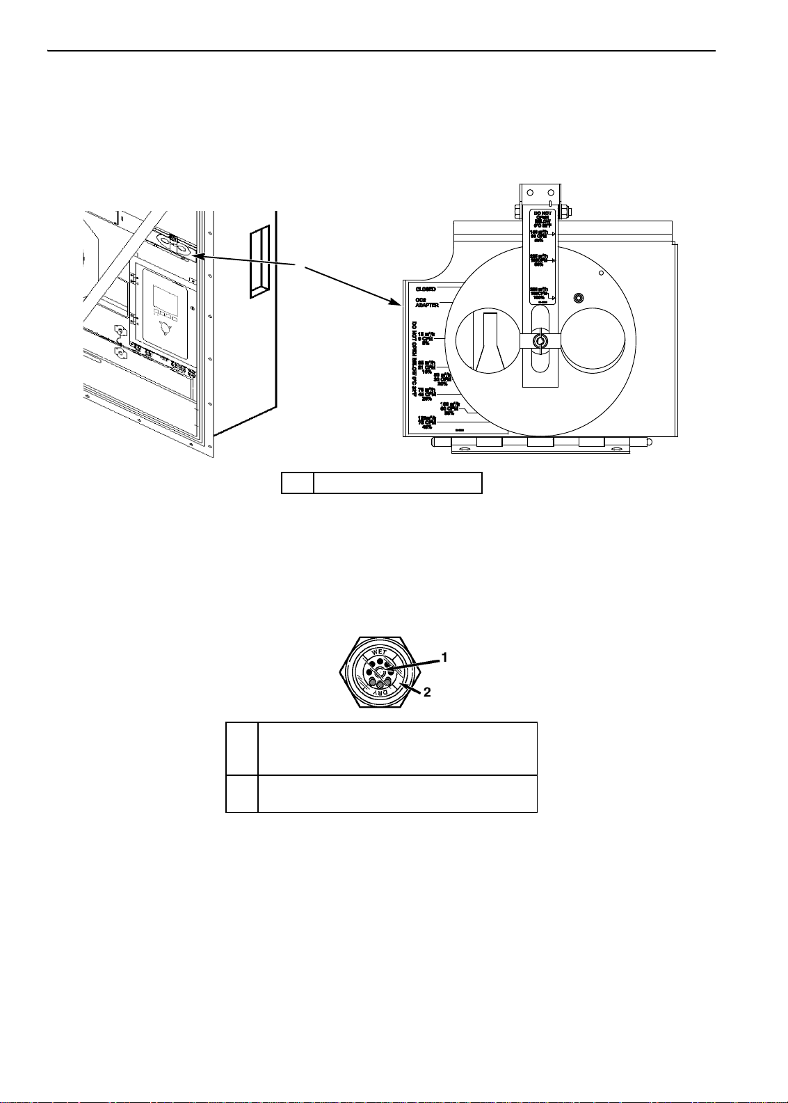
Low Pressure Cutout Switch or Suction Transducer Configuration . . . . . . . . . . . . . . . . . . . . . . . . . . . . . . . . . 158
Discharge and Low Pressure Sensors (Optional) . . . . . . . . . . . . . . . . . . . . . . . . . . . . . . . . . . . . . . . . . . . . . . . 160
Discharge and Low Pressure Sensors Removal . . . . . . . . . . . . . . . . . . . . . . . . . . . . . . . . . . . . . . . . . . . . 160
Discharge and Low Pressure Sensor Installation . . . . . . . . . . . . . . . . . . . . . . . . . . . . . . . . . . . . . . . . . . . . 160
Condenser Fan and Evaporator Fan Rotation . . . . . . . . . . . . . . . . . . . . . . . . . . . . . . . . . . . . . . . . . . . . . . . . . 160
Check Condenser Fan Rotation . . . . . . . . . . . . . . . . . . . . . . . . . . . . . . . . . . . . . . . . . . . . . . . . . . . . . . . . . 160
Check Evaporator Fan Rotation . . . . . . . . . . . . . . . . . . . . . . . . . . . . . . . . . . . . . . . . . . . . . . . . . . . . . . . . . 160
Reversing Power Phase on MAGNUM Units . . . . . . . . . . . . . . . . . . . . . . . . . . . . . . . . . . . . . . . . . . . . . . . 161
Evaporator Heater Selection . . . . . . . . . . . . . . . . . . . . . . . . . . . . . . . . . . . . . . . . . . . . . . . . . . . . . . . . . . . . . . . 161
Extended Capacity Heaters . . . . . . . . . . . . . . . . . . . . . . . . . . . . . . . . . . . . . . . . . . . . . . . . . . . . . . . . . . . . 162
Electric Heaters Malfunction . . . . . . . . . . . . . . . . . . . . . . . . . . . . . . . . . . . . . . . . . . . . . . . . . . . . . . . . . . . . 162
Compressor Discharge Gas Temperature Sensor . . . . . . . . . . . . . . . . . . . . . . . . . . . . . . . . . . . . . . . . . . . . . . 163
Compressor Discharge Temperature Sensor Replacement . . . . . . . . . . . . . . . . . . . . . . . . . . . . . . . . . . . . 163
Temperature Sensors . . . . . . . . . . . . . . . . . . . . . . . . . . . . . . . . . . . . . . . . . . . . . . . . . . . . . . . . . . . . . . . . . . . . 164
Installing Temperature Sensors . . . . . . . . . . . . . . . . . . . . . . . . . . . . . . . . . . . . . . . . . . . . . . . . . . . . . . . . . 165
Testing the Sensors . . . . . . . . . . . . . . . . . . . . . . . . . . . . . . . . . . . . . . . . . . . . . . . . . . . . . . . . . . . . . . . . . . 165
Resistance Values for Temperature Sensors . . . . . . . . . . . . . . . . . . . . . . . . . . . . . . . . . . . . . . . . . . . . . . . 167
Refrigeration Maintenance . . . . . . . . . . . . . . . . . . . . . . . . . . . . . . . . . . . . . . . . . . . . . . . . . . . . . . . . . . . . . . . 169
Introduction . . . . . . . . . . . . . . . . . . . . . . . . . . . . . . . . . . . . . . . . . . . . . . . . . . . . . . . . . . . . . . . . . . . . . . . . . . . . 169
Use the Correct Tools . . . . . . . . . . . . . . . . . . . . . . . . . . . . . . . . . . . . . . . . . . . . . . . . . . . . . . . . . . . . . . . . . . . . 169
Use the Correct Vacuum Pump . . . . . . . . . . . . . . . . . . . . . . . . . . . . . . . . . . . . . . . . . . . . . . . . . . . . . . . . . . . . 169
Use Filters and Cartridges . . . . . . . . . . . . . . . . . . . . . . . . . . . . . . . . . . . . . . . . . . . . . . . . . . . . . . . . . . . . . . . . 169
Use the Correct Refrigerant Recovery Equipment . . . . . . . . . . . . . . . . . . . . . . . . . . . . . . . . . . . . . . . . . . . . . . 169
Detecting Leaks . . . . . . . . . . . . . . . . . . . . . . . . . . . . . . . . . . . . . . . . . . . . . . . . . . . . . . . . . . . . . . . . . . . . . . . . 169
Locating Special Service Fittings . . . . . . . . . . . . . . . . . . . . . . . . . . . . . . . . . . . . . . . . . . . . . . . . . . . . . . . . . . . 169
Perform an Oil Acid Test . . . . . . . . . . . . . . . . . . . . . . . . . . . . . . . . . . . . . . . . . . . . . . . . . . . . . . . . . . . . . . . . . . 170
Isolate the Compressor . . . . . . . . . . . . . . . . . . . . . . . . . . . . . . . . . . . . . . . . . . . . . . . . . . . . . . . . . . . . . . . . . . . 170
Working with a Gauge Manifold . . . . . . . . . . . . . . . . . . . . . . . . . . . . . . . . . . . . . . . . . . . . . . . . . . . . . . . . . . . . 171
Using a New Gauge Manifold Set . . . . . . . . . . . . . . . . . . . . . . . . . . . . . . . . . . . . . . . . . . . . . . . . . . . . . . . 171
Gauge Manifold Valve Positions . . . . . . . . . . . . . . . . . . . . . . . . . . . . . . . . . . . . . . . . . . . . . . . . . . . . . . . . . 171
Gauge Manifold Set Installation & Removal . . . . . . . . . . . . . . . . . . . . . . . . . . . . . . . . . . . . . . . . . . . . . . . . . . . 174
Gauge Manifold Set Installation . . . . . . . . . . . . . . . . . . . . . . . . . . . . . . . . . . . . . . . . . . . . . . . . . . . . . . . . . 174
Removing the Gauge Manifold Set . . . . . . . . . . . . . . . . . . . . . . . . . . . . . . . . . . . . . . . . . . . . . . . . . . . . . . . 175
Checking Refrigerant Charge . . . . . . . . . . . . . . . . . . . . . . . . . . . . . . . . . . . . . . . . . . . . . . . . . . . . . . . . . . . . . . 175
Receiver Tank Sight Glass . . . . . . . . . . . . . . . . . . . . . . . . . . . . . . . . . . . . . . . . . . . . . . . . . . . . . . .
Leak Testing the Refrigeration System
. . . . . . . . . . . . . . . . . . . . . . . . . . . . . . . . . . . . . . . . . . . . . . . . . . . . . . . 177
. . . . . . . . . 176
Using Pressurized Nitrogen . . . . . . . . . . . . . . . . . . . . . . . . . . . . . . . . . . . . . . . . . . . . . . . . . . . . . . . . . . . . . . . 178
Safety Precautions . . . . . . . . . . . . . . . . . . . . . . . . . . . . . . . . . . . . . . . . . . . . . . . . . . . . . . . . . . . . . . . . . . . 178
Purge High Side to Low Side . . . . . . . . . . . . . . . . . . . . . . . . . . . . . . . . . . . . . . . . . . . . . . . . . . . . . . . . . . . 179
Maximum Gas Pressures . . . . . . . . . . . . . . . . . . . . . . . . . . . . . . . . . . . . . . . . . . . . . . . . . . . . . . . . . . . . . . 179
Recovering Refrigerant from the System . . . . . . . . . . . . . . . . . . . . . . . . . . . . . . . . . . . . . . . . . . . . . . . . . . . . . 181
Evacuation and Cleanup of the Refrigeration System . . . . . . . . . . . . . . . . . . . . . . . . . . . . . . . . . . . . . . . . . . . 182
7

Table of Contents
Unit Preparation and Hookup . . . . . . . . . . . . . . . . . . . . . . . . . . . . . . . . . . . . . . . . . . . . . . . . . . . . . . . . . . .182
Unit Evacuation . . . . . . . . . . . . . . . . . . . . . . . . . . . . . . . . . . . . . . . . . . . . . . . . . . . . . . . . . . . . . . . . . . . . . .183
Pressure Rise Test . . . . . . . . . . . . . . . . . . . . . . . . . . . . . . . . . . . . . . . . . . . . . . . . . . . . . . . . . . . . . . . . . . .184
Factors Affecting the Speed of System Evacuation . . . . . . . . . . . . . . . . . . . . . . . . . . . . . . . . . . . . . . . . . .185
Heat Saves Time . . . . . . . . . . . . . . . . . . . . . . . . . . . . . . . . . . . . . . . . . . . . . . . . . . . . . . . . . . . . . . . . . . . .185
Charging the System with Refrigerant . . . . . . . . . . . . . . . . . . . . . . . . . . . . . . . . . . . . . . . . . . . . . . . . . . . . . . . .186
Unit Charging by weight (from an Evacuated Condition) . . . . . . . . . . . . . . . . . . . . . . . . . . . . . . . . . . . . . .186
Compressor Replacement . . . . . . . . . . . . . . . . . . . . . . . . . . . . . . . . . . . . . . . . . . . . . . . . . . . . . . . . . . . . . . . . .187
Compressor Removal . . . . . . . . . . . . . . . . . . . . . . . . . . . . . . . . . . . . . . . . . . . . . . . . . . . . . . . . . . . . . . . . .187
Compressor Installation . . . . . . . . . . . . . . . . . . . . . . . . . . . . . . . . . . . . . . . . . . . . . . . . . . . . . . . . . . . . . . .187
Condenser Coil Replacement . . . . . . . . . . . . . . . . . . . . . . . . . . . . . . . . . . . . . . . . . . . . . . . . . . . . . . . . . . . . . .189
Filter Drier/In-line Filter Replacement . . . . . . . . . . . . . . . . . . . . . . . . . . . . . . . . . . . . . . . . . . . . . . . . . . . . . . . .190
Evaporator Expansion Valve (TXV) Replacement . . . . . . . . . . . . . . . . . . . . . . . . . . . . . . . . . . . . . . . . . . . . . . .192
Economizer Expansion Valve Replacement . . . . . . . . . . . . . . . . . . . . . . . . . . . . . . . . . . . . . . . . . . . . . . . . . . .193
Economizer Heat Exchanger Replacement . . . . . . . . . . . . . . . . . . . . . . . . . . . . . . . . . . . . . . . . . . . . . . . . . . . .195
Economizer Heat Exchanger Removal . . . . . . . . . . . . . . . . . . . . . . . . . . . . . . . . . . . . . . . . . . . . . . . . . . . .195
Economizer Heat Exchanger installation . . . . . . . . . . . . . . . . . . . . . . . . . . . . . . . . . . . . . . . . . . . . . . . . . .196
Receiver Tank/ Water-Cooled Condenser Tank Replacement . . . . . . . . . . . . . . . . . . . . . . . . . . . . . . . . . . . . .197
Tank Removal . . . . . . . . . . . . . . . . . . . . . . . . . . . . . . . . . . . . . . . . . . . . . . . . . . . . . . . . . . . . . . . . . . . . . . .197
Tank Installation . . . . . . . . . . . . . . . . . . . . . . . . . . . . . . . . . . . . . . . . . . . . . . . . . . . . . . . . . . . . . . . . . . . . .197
Vapor Injection Valve Replacement . . . . . . . . . . . . . . . . . . . . . . . . . . . . . . . . . . . . . . . . . . . . . . . . . . . . . . . . .199
Compressor Digital Control Valve Replacement . . . . . . . . . . . . . . . . . . . . . . . . . . . . . . . . . . . . . . . . . . . . . . . .200
Servicing The Unit . . . . . . . . . . . . . . . . . . . . . . . . . . . . . . . . . . . . . . . . . . . . . . . . . . . . . . . . . . . . . . . . . . . . . .202
Taking Care of the Structure . . . . . . . . . . . . . . . . . . . . . . . . . . . . . . . . . . . . . . . . . . . . . . . . . . . . . . . . . . . . . . .202
Inspecting the Unit . . . . . . . . . . . . . . . . . . . . . . . . . . . . . . . . . . . . . . . . . . . . . . . . . . . . . . . . . . . . . . . . . . .202
Checking the Mounting Bolts . . . . . . . . . . . . . . . . . . . . . . . . . . . . . . . . . . . . . . . . . . . . . . . . . . . . . . . . . . .202
Cleaning the Condenser Coil . . . . . . . . . . . . . . . . . . . . . . . . . . . . . . . . . . . . . . . . . . . . . . . . . . . . . . . . . . .203
Cleaning the Evaporator Coil . . . . . . . . . . . . . . . . . . . . . . . . . . . . . . . . . . . . . . . . . . . . . . . . . . . . . . . . . . .203
Cleaning the Defrost Drains . . . . . . . . . . . . . . . . . . . . . . . . . . . . . . . . . . . . . . . . . . . . . . . . . . . . . . . . . . . .203
Positioning the Condenser Fan Blade . . . . . . . . . . . . . . . . . . . . . . . . . . . . . . . . . . . . . . . . . . . . . . . . . . . .203
Positioning the Evaporator Fan Blade . . . . . . . . . . . . . . . . . . . . . . . . . . . . . . . . . . . . . . . . . . . . . . . . . . . .204
Servicing the Fresh Air System . . . . . . . . . . . . . . . . . . . . . . . . . . . . . . . . . . . . . . . . . . . . . . . . . . . . . . . . . . . . .205
Adjusting the Fresh Air Exchange System . . . . . . . . . . . . . . . . . . . . . . . . . . . . . . . . . . . . . . . . . . . . . . . . .205
Diagnosis: Troubleshooting, Warnings and Alarm Codes . . . . . . . . . . . . . . . . . . . . . . . . . . . . . . . . . . . . .207
Introduction . . . . . . . . . . . . . . . . . . . . . . . . . . . . . . . . . . . . . . . . . . . . . . . . . . . . . . . . . . . . . . . . . . . . . . . . . . . .207
Controller Diagnostics . . . . . . . . . . . . . . . . . . . . . . . . . . . . . . . . . . . . . . . . . . . . . . . . . . . . . . . . . . . . . . . . . . . .207
Warnings and Controller Actions . . . . . . . . . . . . . . . . . . . . . . . . . . . . . . . . . . . . . . . . . . . . . . . . . . . . . . . . . . . .214
Wiring and Schematic Diagrams Index . . . . . . . . . . . . . . . . . . . . . . . . . . . . . . . . . . . . . . . . . . . . . . . . . . . . .254
Controller Menu Guide . . . . . . . . . . . . . . . . . . . . . . . . . . . . . . . . . . . . . . . . . . . . . . . . . . . . . . . . . . . . . . . . . . .260
8

Safety Instructions
General Precautions
• Always wear goggles or safety glasses. Refrigerant liquid and battery acid can permanently damage
the eyes.
• Never operate the unit with the discharge valve closed. Never close the compressor discharge valve
with the unit in operation.
• Keep your hands, clothing and tools clear of the fans when the refrigeration unit is running. If it is
necessary to run the refrigeration unit with covers removed, be very careful with tools or meters being
used in the area.
• Check the condition of the gauge manifold hoses. Never let the hoses come in contact with a fan
motor blade or any hot surface.
• Never apply heat to a sealed refrigeration system or container.
• Fluorocarbon refrigerants produce toxic gases in the presence of an open flame or electrical arc. The
gases are severe respiratory irritants capable of causing death.
• Firmly tighten all mounting bolts. Check each bolt for correct length for their particular application.
• Use extreme caution when drilling holes in the unit. The holes may weaken structural components.
Holes drilled into electrical wiring can cause fire or explosion. Holes drilled into the refrigeration
system may release refrigerant.
• Use caution when working around exposed coil fins. The fins can cause painful lacerations.
• Use caution when working with a refrigerant or refrigeration system in any closed or confined area
with a limited air supply (for example, a trailer , container or in the hold of a ship). Refrigerant tends to
displace air and can cause oxygen depletion. This can result in suffocation and possible death.
• Use caution and follow the manufacturer’s suggested practices when using ladders or scaffolds
.
Refrigerant Oil Precautions
Observe the following precautions when working with or around refrigerant oil:
• Do not allow refrigerant oil to contact your eyes.
• Rubber gloves are recommended when handling Polyol Ester based refrigerant oil.
• Do not allow prolonged or repeated contact with skin or clothing.
• Immediately wash all exposed skin after handling refrigerant oil.
Use the following First Aid practices if needed.
Eyes: Immediately flush eyes with large amounts of water. Continue flushing for at least 15 minutes
while holding the eyelids open. Get prompt medical attention.
Skin: Remove contaminated clothing. Wash thoroughly with soap and water. Get medical attention if
irritation persists.
Inhalation: Move victim to fresh air. Restore breathing if necessary. Stay with victim until arrival of
emergency personnel.
Ingestion: Do not induce vomiting. Contact a local poison control center or physician immediately.
9

Safety Instructions
Electrical Precautions
The possibility of serious or fatal injury from electrical shock exists when servicing a refrigeration unit.
Extreme care must be used when working with a refrigeration unit that is connected to its power source.
Extreme care must be used even if the unit is not running. Lethal voltage potentials can exist at the unit
power cord, inside the control box, inside any high voltage junction box, at the motors and within the
wiring harnesses.
Precautions
In general disconnect the units power cord before repairi ng or changing any electrical
components.
Note that even though the controller is turned off, one of the phases is still live and represents
a potential danger of electrocution
Where turning of the unit is not possible (for example at voltage measuring or troubleshooting), follow
safety precautions below.
• Turn the unit On/Off switch to Off before connecting or disconnecting the unit power plug. Never
attempt to stop the unit by disconnecting the power plug.
• Be certain the unit power plug is clean and dry before connecting it to a power source.
• Use tools with insulated handles. Use tools that are in good condition. Never hold metal tools in your
hand if exposed, energized conductors are within reach.
• Do not make any rapid moves when working with high voltage circuits. Do not grab a falling tool or
other object. People do not contact high voltage wires on purpose. It occurs from an unplanned
movement.
• Treat all wires and connections as high voltage until ammeter and wiring diagram show otherwise.
• Never work alone on high voltage circuits on the refrigeration unit. Another person should always be
standing by in the event of an accident to shut off the refrigeration unit and to aid a victim.
• Have electrically insulated gloves, cable cutters and safety glasses available in the immediate vicinity
in the event of an accident.
First Aid
IMMEDIATE action must be initiated after a person has received an electrical shock. Obtain immediate
medical assistance.
The source of shock must be immediately removed. Shut down the power or remove the victim from the
source. If it is not possible to shut off the power , the wire should be cut with either an insulated instrument
(e.g., a wooden handled axe or cable cutters with heavy insulated handles). A rescuer wearing electrically
insulated gloves and safety glasses could also cut the wire. Do not look at the wire while it is being cut.
The ensuing flash can cause burns and blindness.
Pull the victim off with a non-conductive material if the victim has to be removed from a live circuit. Use
the victim’s coat, a rope, wood, or loop your belt around the victim’s leg or arm and pull the victim off.
Do not touch the victim. You can receive a shock from current flowing through the victim’s body.
Check immediately for the presence of a pulse and respiration after separating the victim from power
source. If a pulse is not present, start CPR (Cardio Pulmonary Resuscitation) and call for emergency
medical assistance. Respiration may also be restored by using mouth-to-mouth resuscitation.
10

Safety Instructions
Low Voltage
Control circuits are low voltage (24 Vac and 12 Vdc). This voltage potential is not considered dangerous.
Large amount of current available (over 30 amperes) can cause severe burns if shorted to ground. Do not
wear jewelry, watch or rings. These items can shortcut electrical circuits and cause severe burns to the
wearer.
Electrostatic Discharge Precautions
Precautions must be taken to prevent electrostatic discharge while servicing the MP-3000a
microprocessor and related components. The risk of significant damage to the electronic components of
the unit is possible if these precautionary measures are not followed. The primary risk potential results
from the failure to wear adequate electrostatic discharge preventive equipment when handling and
servicing the controller. Th e second cause results from electric welding on the unit and container chassis
without taking precautionary steps.
Electrostatic Discharge and the Controller
You must avoid electrostatic discharges when servicing the controller. Solid-state integrated circuit
components can be severely damaged or destroyed with less than a small spark from a finger to metal
object. You must rigidly adhere to the following statements when servicing these units. This will avoid
controller damage or destruction.
• Disconnect all power to the unit.
• Avoid wearing clothing that generates static electricity (wool, nylon, polyester, etc.).
• Do wear a static discharge wrist strap (refer to Tool Catalog) with the lead end connected to the
controller's ground terminal. These straps are available at most electronic equipment distributors. Do
not wear these straps with power applied to the unit.
• Avoid contacting the electronic components on the circuit boards of the unit being serviced.
• Leave the circuit boards in their static proof packing materials until ready for installation.
• Return a defective controller for repair in the same static protective packing materials from which the
replacement component was removed.
• Check the wiring after servicing the unit for possible errors. Complete this task before restoring
power.
11

Safety Instructions
Welding of Units or Containers
Electric welding can cause serious damage to electronic circuits when performed on any portion of the
refrigeration unit, container or container chassis with the refrigeration unit attached. It is necessary to
ensure that welding currents are not allowed to flow through the electronic circuits of the unit. The
following statements must be rigidly adhered to when servicing these units to avoid damage or
destruction.
• Disconnect all power to the refrigeration unit.
• Disconnect all quick-disconnect wire harnesses from the back of the controller.
• Disconnect all wire harnesses from the Remote Monitor Modem (RMM).
• Switch all of the electrical circuit breakers in the control box to the Off position.
• Weld unit and/or container per normal welding procedures. Keep ground return electrode as close to
the area to be welded as practical. This will reduce the likelihood of stray welding currents passing
through any electrical or electronic circuits.
• The unit power cables, wiring and circuit breakers must be restored to their normal condition when
the welding operation is completed.
Removing Refrigerant Properly
Use a refrigerant recovery process that prevents or absolutely minimizes refrigerant escaping to the
atmosphere. Fluorocarbon refrigerants are classified as safe refrigerants when proper tools and
procedures are used. Certain precautions must be observed when handling them or servicing a unit in
which they are used.
Fluorocarbon refrigerants evaporate rapidly, freezing anything they contact when exposed to the
atmosphere in the liquid state. In the event of frost bite, attempt to protect the frozen area from further
injury, warm the affected area rapidly, and maintain respiration.
• Eyes: For contact with liquid, immediately flush eyes with large amounts of water and get prompt
medical attention.
• Skin: Flush area with large amounts of lukewarm water. Do not apply heat. Remove contaminated
clothing and shoes. Wrap burns with dry, sterile, bulky dressing to protect from infection/injury. Get
medical attention. Wash contaminated clothing before reuse.
• Inhalation: Move victim to fresh air and use CPR or mouth-to-mouth ventilation, if necessary. Stay
with victim until arrival of emergency medical personnel.
12
Safety Instructions
2
BEN074
AXA0214
AXA0215
AXA0218
AXA0217
AXA0216
1
3
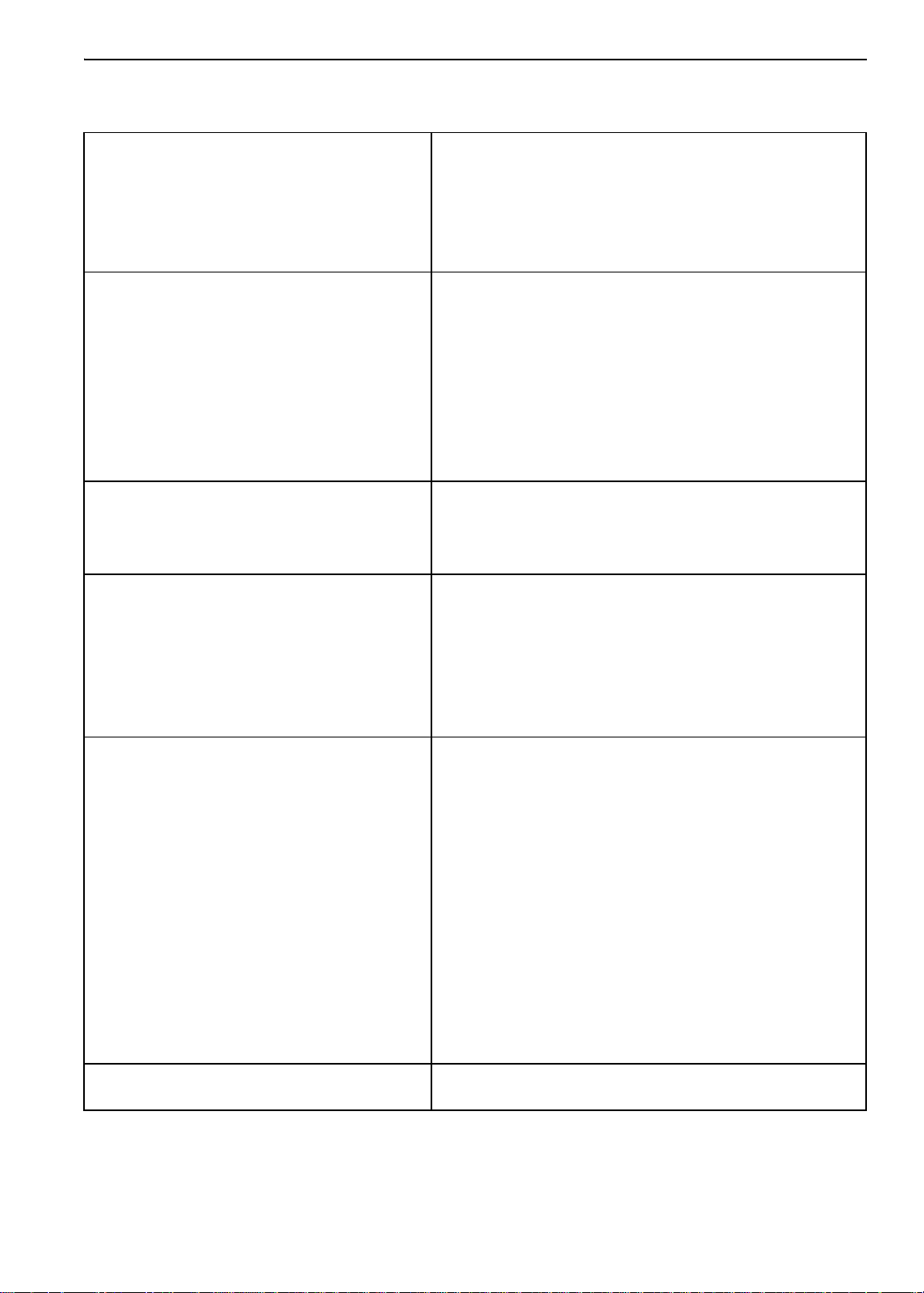
1. Controller Nameplate
2. Unit Nameplate
3. Compressor Nameplate
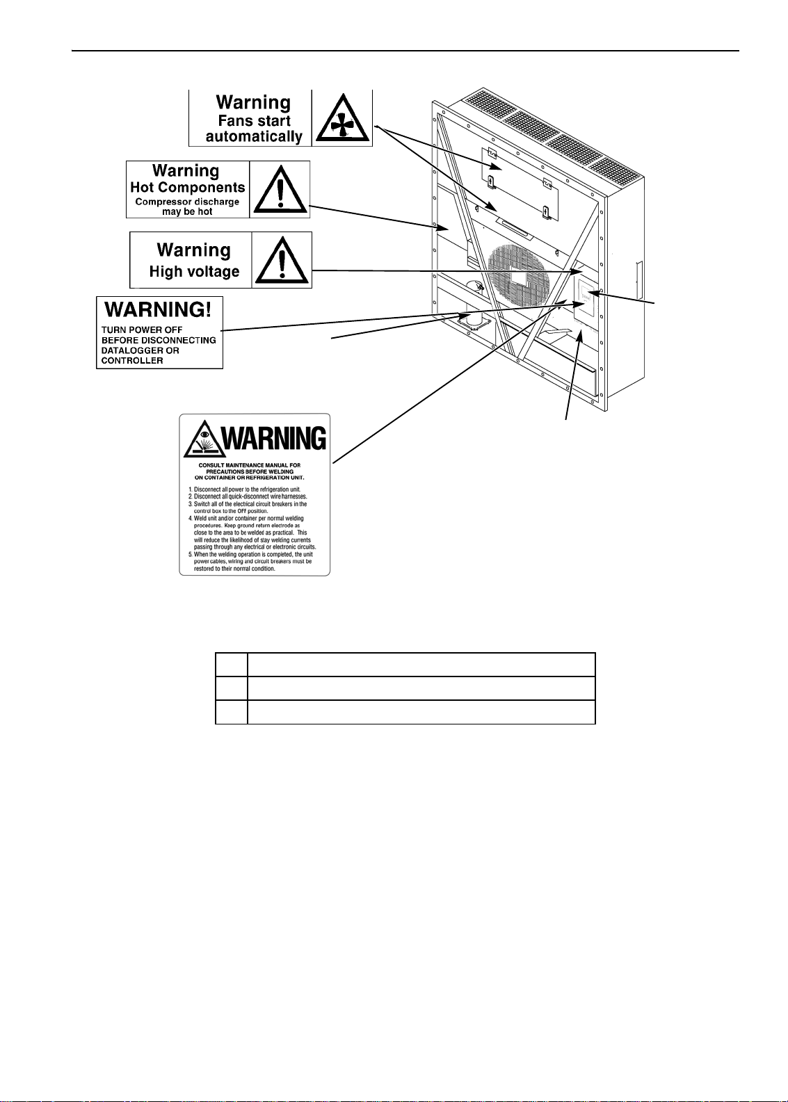
Nameplate and Warning Locations
13

Safety Instructions
Identifying Unit Safety and Warning Decals
Serial number decals, refrigerant type decals and warning decals appear on all Thermo King® equipment.
These decals provide information that may be needed to service or repair the unit. Service technicians
should read and follow the instructions on all warning decals. See Figure .
Locating Serial Numbers
Serial numbers can be found on the component’s nameplate.
• Electric Motor Nameplate: Attached to the motor housing.
• Compressor Nameplate: On front of the compressor.
• Unit Nameplate: On unit frame in power cord storage compartment.
• MP-4000 Controller Nameplate: On top of controller.
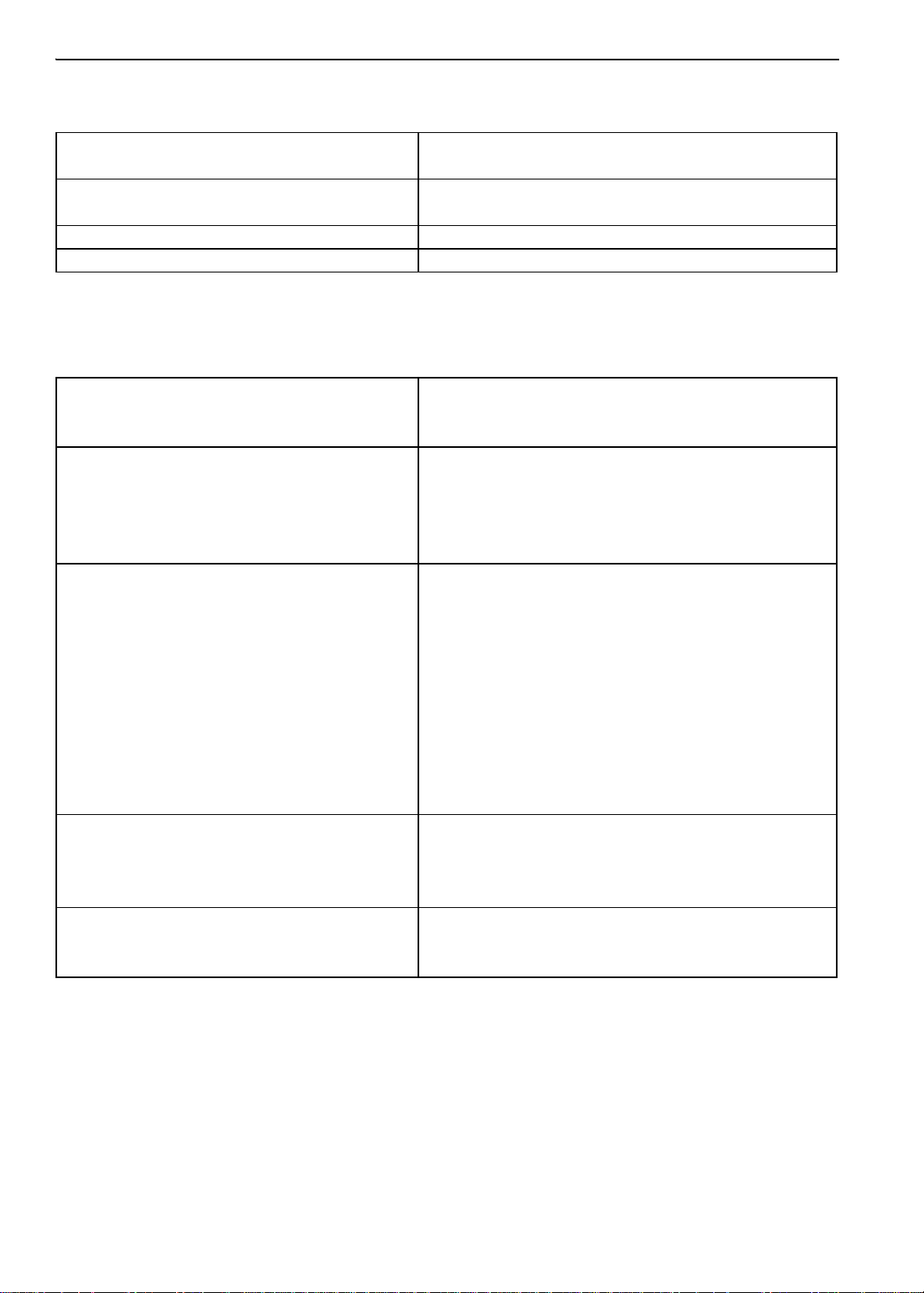
Component Serial Number Identification
To better identify the different electronic components, our supplier has changed their serial number
labeling on the MP-4000 controller and power module. The label will show part number, date, and
sequence.
MP4000 Controller
New label shows controller ID ABS782800212245390
Part number Date 2012 24 wk Sequence
ABS7828002 1224 5390
ID in controller would show 1224-5390
Figure 1: Label on Controller Figure 2: ID in Controller
14
Figure 3: Controller ID Shown in Datalogger
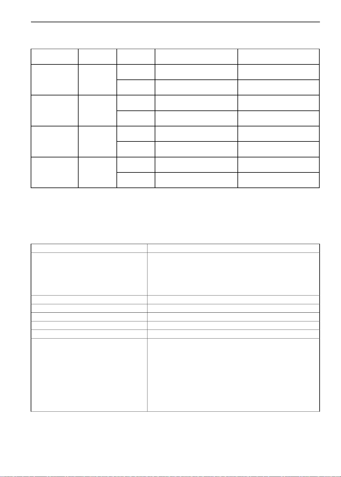
Service Guide
Service Guide
A closely followed maintenance program will help to keep your Thermo King unit in top operating
condition.
The following service guide table should be used as a guide when inspecting or servicing components on
this unit.
Every
Pretrip
• Perform a controller pretrip inspection (PTI) check.
• • • Visually check condenser fan and evaporator fan.
• • • Visually inspect electrical contacts for damage or loose connections.
• • • Visually inspect wire harnesses for damage or loose connections.
• • • Check refrigerant charge.
• • • Visually inspect unit for damaged, loose or broken parts.
• • • Tighten unit, compressor and fan motor mounting bolts.
1,000
Hours
• • Download the data logger and check data for correct logging.
• • Check for proper discharge and suction pressures.
• • Clean entire unit including condenser and evaporator coils, and defrost drains.
Annual/
Yearly
Electrical
• Check operation of protection shutdown circuits.
Refrigeration
• Check filter drier/in-line filter for a restriction pressures.
Structural
Inspect/Service These Items
NOTE: If a unit has been carrying cargo which contains a high level of sulphor or phosphorous (e.g.
garlic, salted fish etc.), it is recommended that clean evaporator coil after each trip.
15
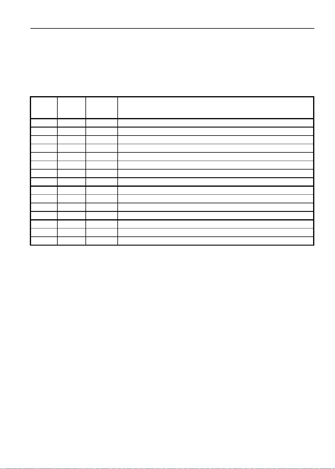
Specifications
System Net Cooling Capacity— Full Cool
MAGNUM+ Model — Air Cooled
Condensing*
460/230V, 3 Phase, 60 Hz Power
Return air to
evaporator coil
inlet
21.1 C (70 F) 56,700 16.603 11.55
1.7 C (35 F) 40, 945 11.990 11.03
-17.8 C (0 F) 24,785 7.258 7.57
-29 C (-20 F) 17, 215 5,041 6.6
-35 C (-31 F) 14,000 4.104 6.03
*System net cooling capacity with a 38 C (100 F) ambient air
Net Cooling Capacity Power
Consump
60 Hz
Capacity
B/hr
temperature and R-404A.
60 Hz
Capacity
kW
60 Hz Power
kW
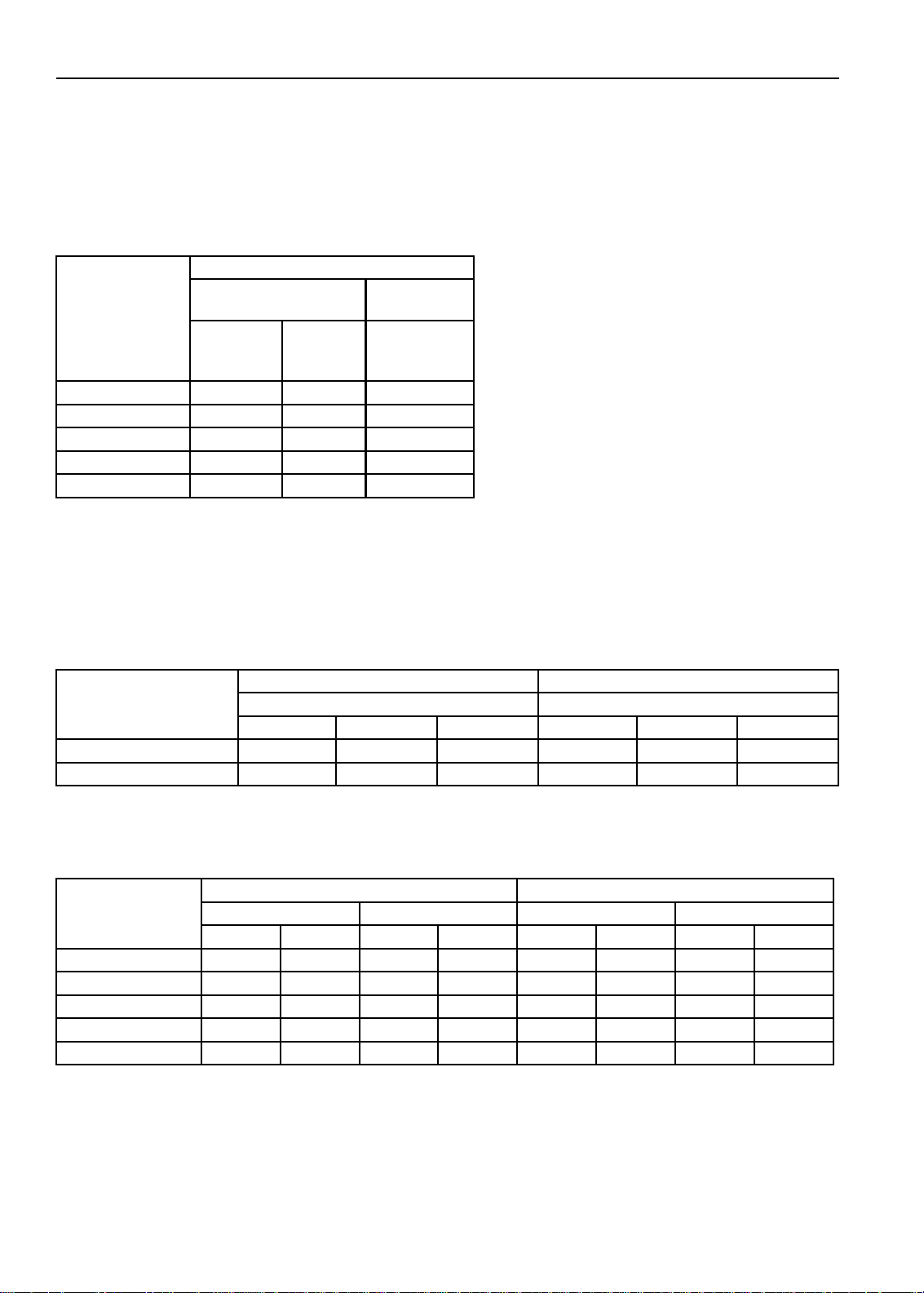
Evaporator Airflow Specifications
System Net Heating Capacity*
460/230V, 3 Phase, 60 Hz Power 380/190V, 3 Phase, 50 Hz Power
Heating Capacity Heating Capacity
Watts Kcal/hr BTU/hr Watts Kcal/hr BTU/hr
MAGNUM+ normal 5,250 4,515 17,914 3,900 3,353 13,300
MAGNUM+ extended 7,250 6,234 24,738 5,550 4,772 18,937
*System net heating capacity includes electric resistance rods and fan heat.
MAGNUM+
External Static
Pressure (water
column)
0 mm (0 in.) 6,560 3,860 3,170 1,865 5,480 3,225 2,710 1,595
10 mm (0.4 in.) 5,820 3,425 1,770 1,040 4,530 2,665 930 545
20 mm (0.8 in.) 5,000 2,940 — — 3,750 2,205 — —
30 mm (1.2 in.) 4,430 2,610 — — 2,930 1,725 — —
40 mm (1.6 in.) 3,520 2,070 — — 1,870 1,100 — —
460/230V, 3 Phase, 60 Hz Power 380/190V, 3 Phase, 50 Hz Power
High Speed Low Speed High Speed Low Speed
3
m
/hr ft3/min m3/hr ft3/min m3/hr ft3/min m3/hr ft3/min
16
Electrical System Specifications
Compressor Motor:
Type 460/380V, 60/50 Hz, 3 Phase
Kilowatts 4.48 kW @ 460V, 60 Hz
Horsepower 6.0 hp @ 460V, 60 Hz
RPM 3550 RPM @ 460V, 60 Hz
Locked Rotor Amps 70 amps @ 460V, 60 Hz
Condenser Fan Motor:
Type 460/380V, 60/50 Hz, 3 Phase
Kilowatts 0.55 kW @ 460V, 60 Hz
Horsepower 0.75 hp @ 460V, 60 Hz
Number: All Models 1
Motor:
RPM 1725 RPM @ 460V, 60 Hz
Full Load Amps 1.0 amps @ 460V, 60 Hz; 1.0 amps @ 380V, 50 Hz
Locked Rotor Amps 3.9 amps @ 460V, 60 Hz; 3.7 amps @ 380V, 50 Hz
Evaporator Fan Motors:
Type 460/380V, 60/50 Hz, 3 Phase
Kilowatts 0.75 kW @ 460V, 60 Hz
Horsepower 1.0 hp @ 460V, 60 Hz
Motor:
RPM (Each): High Speed 3450 RPM @ 460V, 60 Hz
Low Speed 1725 RPM @ 460V, 60 Hz
Full Load Amps (Each): High Speed 1.6 amps @ 460V, 60 Hz
Low Speed 0.8 amps @ 460V, 60 Hz
Locked Rotor Amps: High Speed 10.5 amps @ 460V, 60 Hz
Low Speed 9.0 amps @ 460V, 60 Hz
Electrical Resistance Heater Rods:
Type 460/380V, 60/50 Hz, 3 Phase
Number:
Normal Capacity
Normal Capacity
Extended Capacity
Watts (Each):
Normal Capacity
Normal Capacity
Extended Capacity
Current Draw (Amps):
Normal Capacity
Extended Capacity
Control Circuit Voltage:
6 (18 ga wire)
3 (18 ga wire)
3 (16 ga wire)
680 Watts @ 460V, 60 Hz
1360 Watts @ 460V, 60 Hz
2000 Watts @ 460V, 60 Hz
5 amps total @ 460V across each phase at heater contractor
4.5 amps total @ 460V across each phase at heater contractor
29 Vac @ 60 Hz
Specifications
17
Specifications
Refrigeration System Specifications
Compressor:
Model No.: ZMD18KVE-TFD-277, Scroll
Refrigerant Charge:
MAGNUM+ 4.0 Kg (8.0 lb.) R-404A
Compressor Oil Capacity 1.77 liter (60 oz.)*
Compressor Oil Type: Polyol Ester Based Type (required), (refer to Tool Catalog)**
*When the compressor is removed from the unit, oil level should be noted or the oil removed from the compressor should be
measured so that the same amount of oil can be maintained in the replacement compressor.
**Do not use or add standard synthetic or mineral oils to the refrigeration system. If Ester based oil becomes contaminated
with moisture or with standard oils, dispose of properly — Do Not Use!
High Pressure Cutout Switch:
Cutout 3240 ± 48 kPa, 32.4 ± 0.5 bar, 470 ± 7 psig
Cutin 2586 ± 262 kPa, 25.9 ± 2.6 bar, 375 ± 38 psig
Low Pressure Cutout Switch:
Cutout -17 to -37 kPa, -0.17 to -0.37 bar, 5 to 11 in. Hg vacuum
Cutin 28 to 48 kPa, 0.28 to 0.48 bar, 4 to 7 psig
High Pressure Relief Valve:
Relief Temperature 99 C, 210 F
Vapor Injection Control:
V apor injection valve is energized (open) continuously when
the compressor duty cycle (ON time) is 100 percent (Full
Modulation Cool or Power Limit
Compressor Discharge Temperature Control:
Vapor Injection Valve Energizes (Opens) 138 C (280 F)
Vapor Injection Valve De-energizes (Closes)
Compressor Shutdown (Auto Reset) 148 C (298 F)
Vapor Injection Valve (Compressor):
Voltage 24 Vac
Current 0.85 amps
Cold Resistance 5.6 ohms
Compressor Digital Control Valve:
Voltage 24 Vac
Current Draw 0.85 amps
Cool). High compressor discharge temperature may cause
the vapor injection valve to energize (open) but only while
the Compressor Digital Control valve is not energized
(closed).
6 C (10.7 F) below energize temperature
(132 C [123 F])
18
Specifications
Normal R-404A System Operating Pressures (Scroll Compressor)
Container T emp.
21 C (70 F) Cool
2 C (35 F) Cool
-18 C (0 F) Cool
-29 C (-20 F) Cool
Suction and discharge pressures vary too greatly during Modulation Cool to use for evaluating or diagnosing refrigeration
system performance. During the Modulation Cool mode, the suction pressure will vary between 100 and 450 kPa, 1.0 and 4.5
bar, 15 and 65 psig depending upon the percent (percent) cooling capacity.
**Discharge pressure is determined by condenser fan cycling.
Operating
Mode
Ambient
Temp.
27 to 38 C, 80
to 100 F
16 to 27 C, 60
to 80 F
27 to 38 C, 80
to 100 F
16 to 27 C, 60
to 80 F
27 to 38 C, 80
to 100 F
16 to 27 C, 60
to 80 F
27 to 38 C, 80
to 100 F
16 to 27 C, 60
to 80 F
Suction Pressure Discharge Pressure
410 to 670 kPa, 4.10 to 6.70
bar, 59 to 97 psig
400 to 600 kPa, 4.00 to 6.00
bar, 58 to 87 psig
385 to 425 kPa, 3.85 to 4.25
bar, 56 to 62 psig
345 to 385 kPa, 3.45 to 3.85
bar, 50 to 56 psig
214 to 228 kPa, 2.14 to 2.28
bar, 31 to 33 psig
200 to 215 kPa, 2.00 to 2.15
bar, 29 to 31 psig
145 to 160 kPa, 1.45 to 1.60
bar, 21 to 23 psig
130 to 145 kPa, 1.30 to 1.45
bar, 19 to 21 psig
2140 to 2650 kPa, 21.40 to
26.50 bar, 310 to 385 psig
1725 to 2140 kPa, 17.25 to
21.40 bar, 250 to 310 psig
1860 to 2380 kPa, 18.60 to
23.80 bar, 270 to 345 psig
1450 to 1860 kPa, 14.50 to
18.60 bar, 210 to 270 psig**
1515 to 2035 kPa, 15.15 to
20.35 bar, 220 to 295 psig**
1100 to 1515 kPa, 11.00 to
15.15 bar, 160 to 220 psig**
1450 to 1965 kPa, 14.50 to
19.65 bar, 210 to 285 psig**
1035 to 1450 kPa, 10.35 to
14.50 bar, 150 to 210 psig**
MP-4000 Controller Specifications
Temperature Controller:
MP-4000 is a controller module for the Thermo King Magnum+
Unit. Additional requirements can be met by means of expansion
Type
Setpoint Range -40.0 to +30.0 C (-31.0 to +86.0 F)
Digital Temperature Display -60.0 to +80.0 C (-76.0 to +176.0 F)
Controller Software (Original Equipment):
Version See controller identification decal
Defrost Initiation:
Evaporator Coil Sensor
modules. The MP4000 is solely responsible for temperature
regulation of the reefer container, but other monitoring equipment
can be used in conjunction with the MP 4000 - such as a chart
recorder.
• Manual Switch or Demand Defrost Initiation: Coil must be
• Timed Defrost Initiation: Coil must be below 4 C (41 F). Defrost
v
below 18 C (65 F). Defrost cycle starts when technician or
controller requests defrost initiation.
cycle starts 1 minute after the hour immediately following a
defrost timer request for defrost initiation. For example, if the
defrost timer requests a defrost cycle at 7:35, the defrost cycle
will start at 8:01. Datalogger will record a Defrost event for each
interval in which a Defrost cycle is pending or active (i.e. both the
8:00 and 9:00 data logs).
19
Specifications
MP-4000 Controller Specifications (Continued)
Demand defrost function initiates defrost when:
• Temperature difference between the return air sensor and
Demand Defrost
Defrost Timer:
Chilled mode
Frozen mode
Reset to Base Time
Defrost Termination:
Defrost (Coil) Sensor
Termination Timer
Power Off Turning Unit On/Off switch Off terminates defrost
Compressor Shutdown Protection
(Auto Reset):
Stops Compressor 148 C (298 F)
Allows Compressor Start 90 C (194 F)
Bulb Mode:
Evaporator Fan Speed Settings
Defrost Termination Temperature Setting 4 to 30 C (40 to 86 F)
defrost (evaporator coil) sensor is too large for 90 minutes
• Temperature difference between the supply air sensors and
return air sensor is too large
Evaporator Coil Temperature must be below 5C (41 F) to activate
the defrost compressor hour timer.
There is an interval set for defrosting, however, the defrost timer is
built intelligent - it detects whether or not there is ice building up on
the coil. If there is no ice building up on the coil, it extends the
defrost interval, and if there is Ice building up earlier on the coil it
reduces the defrost interval. The maximum interval is 48 hours.
Every 8 hours of compressor operation. Defrost interval increases 2
hours each timed defrost interval. Maximum time interval in Frozen
mode is 24 hours.
Defrost timer resets if the unit is off more than 12 hours, setpoint is
changed more than 5 C (9 F) or PTI pretrip test occurs.
Chilled mode: Terminates defrost when coil sensor temperature
rises to 18 C (65 F).
Frozen mode: Terminates defrost when coil sensor temperature
rises to 18 C (65 F).
Terminates defrost after 90 minutes at 60 HZ operation if coil
sensor has not terminated defrost (120 minutes at 50 Hz operation)
Flow High: High speed only
Flow Low: Low speed only
Flow Cycle: Fans will cycle between low and high speed every 60
minutes
Physical Specifications
Fresh Air Exchange Venting System
(Adjustable):
3
MAGNUM+
0 to 225 m
0 to 185 m
Evaporator Fan Blade Specifications:
MAGNUM+:
Diameter 355 mm (14.0 in.)
Pitch 25°
Number of Fans 2
20
/hr (0 to 168 ft3/min.) @ 60 Hz
3
/hr (0 to 139 ft3/min.) @ 50 Hz
Physical Specifications (Continued)
AMA313
Weight (net):
MAGNUM+ Base Unit 380 Kg (875 lb.)
Water-cooled Condenser-Receiver Option 13.6 Kg (30 lb.)
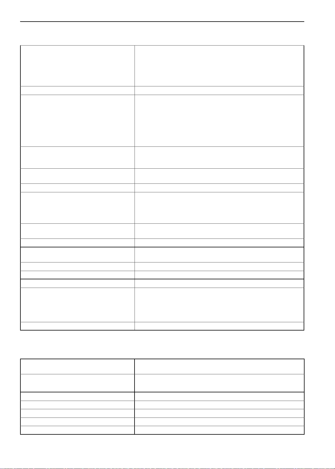
Specifications
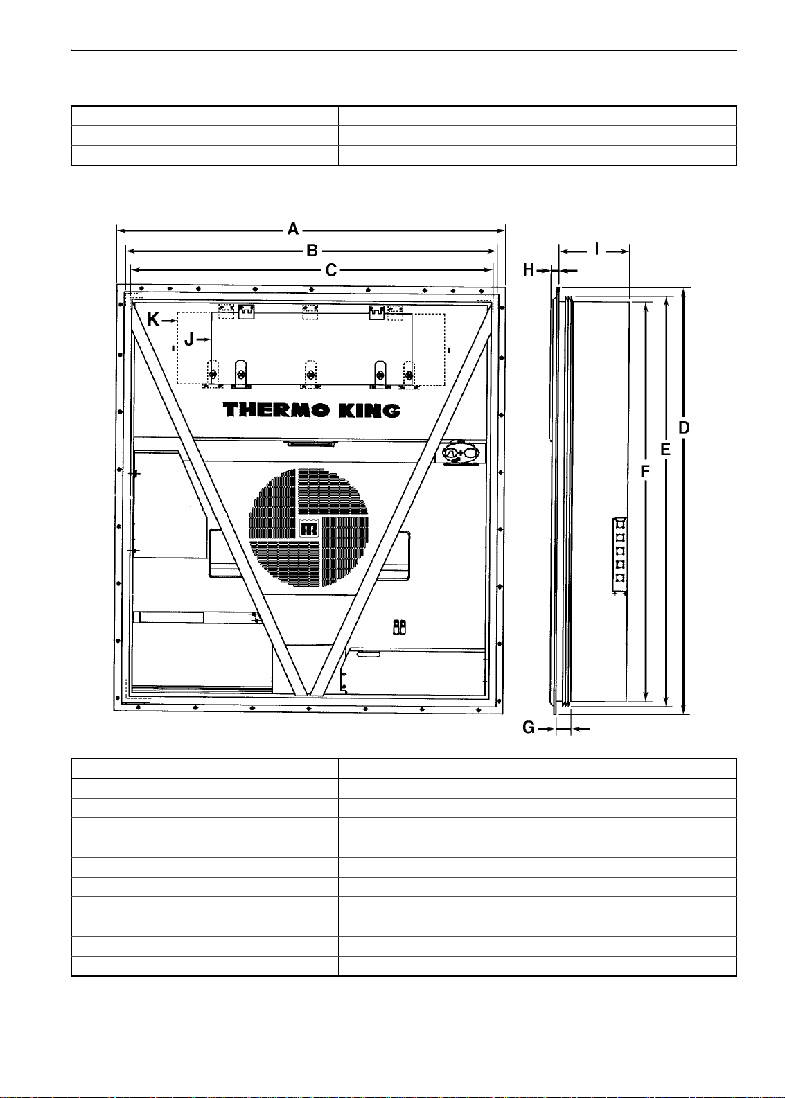
Unit Dimensions:
A = Flange Width 2025.5 mm (79.74 in.)
B = Gasket Width 1935 mm (76.18 in.)
C = Unit Width 1894 mm (74.57 in.)
D = Flange Height 2235.2 mm (88.00 in.)
E = Gasket Height 2140 mm (84.25 in.)
F = Unit Height 2094 mm (82.44 in.)
G = Gasket Depth 72 mm (2.83 in.) from back of flange
H = Maximum Protrusion 37 mm (1.46 in.) from back of flange
I = MAGNUM+ 420.0 mm (16.54 in.) from back of flange
J = MANGUM+ Evaporator Access Door
Figure 1: Physical Specifications
21
Unit Description, Features & Options
BEN074
Introduction
This chapter will briefly describe the following items:
• General Unit Description.
• Standard Component Descriptions.
• Optional Component Descriptions.
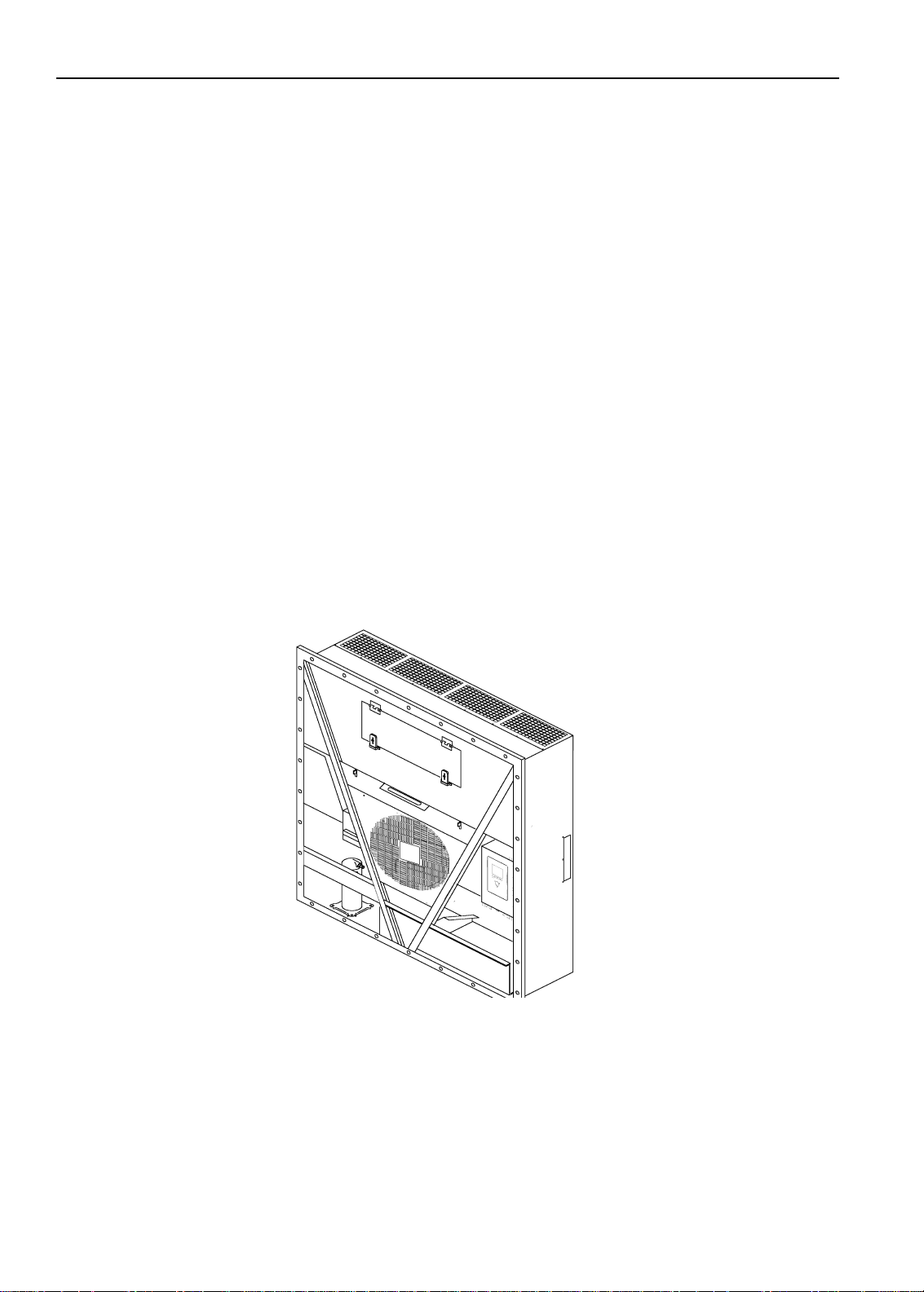
General Description
MAGNUM units are all-electric, single-piece, refrigeration units with bottom air supply. The unit is
designed to cool and heat containers for shipboard or overland transit. The unit mounts in the front wall of
the container. Fork lift pockets are provided for installation and removal of the unit.
The frame and bulkhead panels are constructed of aluminum and are treated to resist corrosion. A
removable evaporator compartment door provides service access. All components except the evaporator
coil and electric heaters can be replaced from the front of the unit.
Each unit is equipped with an 18.3 m (60 ft.) power cable for operation on 460-380V/3 Ph/60-50 Hz
power. The unit power cable is stored below the control box in the condenser section.
Each unit is equipped with 460-380V/3 Ph/60-50 Hz electric motors. An automatic phase correction
system provides the proper electrical phase sequence for condenser fan, evaporator fan and compressor
operation.
Figure 2: MAGNUM+ Unit
The MAGNUM+ container unit features the following components. Each component will be described
briefly on the following pages.:
• Scroll Compressor
• Compressor Digital Control Valve
• Economizer Heat Exchange System
• Temperature Sensors
22

Unit Description, Features & Options
• Fresh Air Exchange System
• Receiver Tank Sight Glass
• Evaporator Fans
• Condenser Fan Control
• Suction/Discharge Pressure Sensor (Optional)
• Remote Monitoring Receptacle Option (4-pin) (optional)
• Remote Monitoring Modem (RMM, RMM+) (Optional)
• USDA Cold Treatment Temperature Recording (Optional)
•
Advanced Fresh Air Management (AFAM) and Advanced Fresh Air Management Plus (AFAM+)
(Optional)
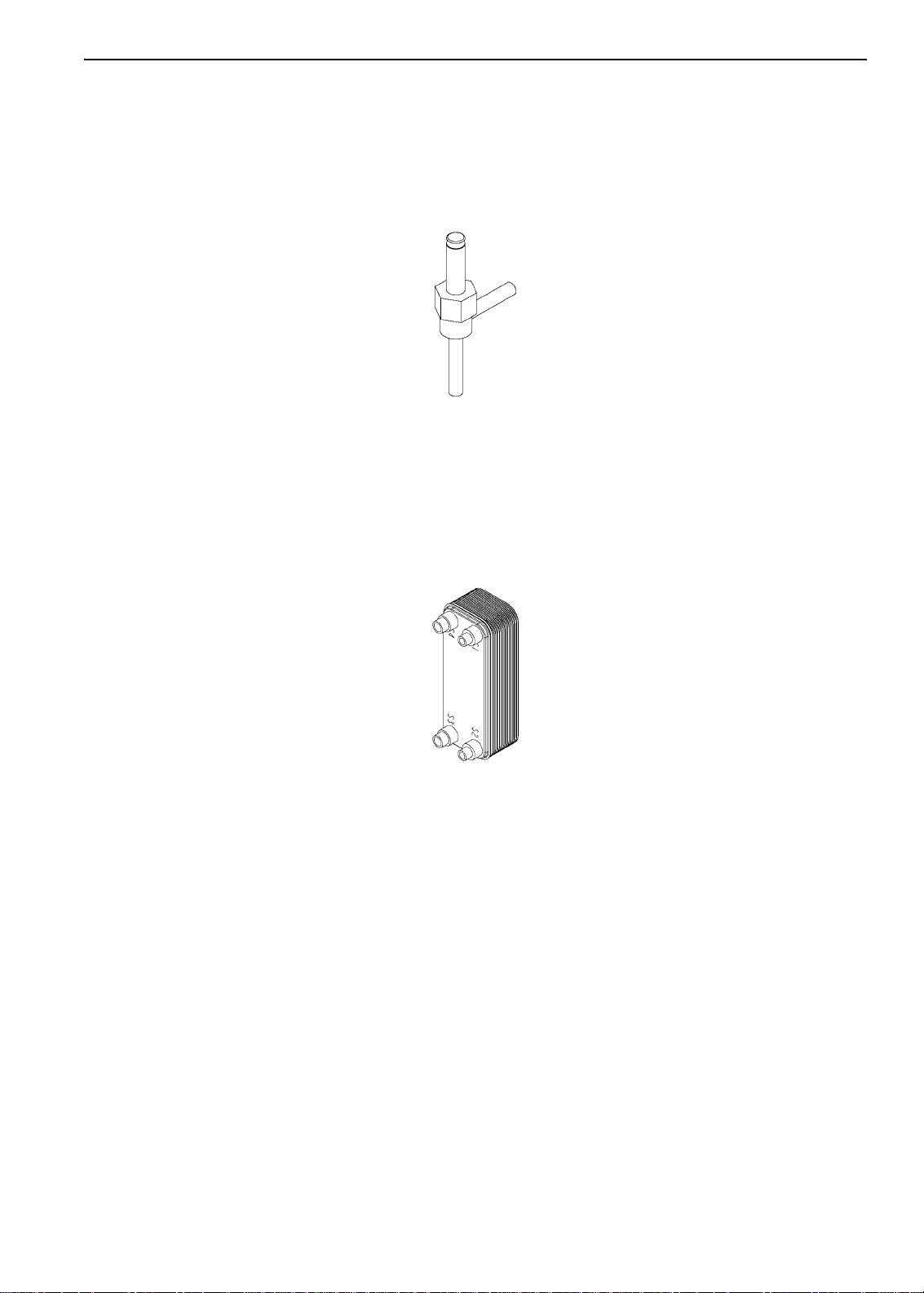
Scroll Compressor
The scroll compressor features a digital port and an intermediate suction port.
Digital Port
The digital port provides cooling capacity control. The digital port is located at the top of the scroll
assembly on the compressor body. When energized, the Digital Control valve disengages the scroll set.
This reduces pumping capacity to zero.
Intermediate Suction Port
The intermediate suction port draws suction gas from the economizer heat exchanger into the scroll
assembly of the compressor. The scroll seals of f the suction port . This prevents economizer gas from
leaking back to the main suction port. It also prevents the economizer gas pressure from influencing the
cooling capacity of the unit evaporator (main suction gas pressure).
Figure 3: Scroll Compressor
23
Unit Description, Features & Options
1
BEN074
MP 3000 MRB
Red Holder
F 20 amp Fuse
PM 4000 Power Module
Black Holder
FF 20 amp Fuse
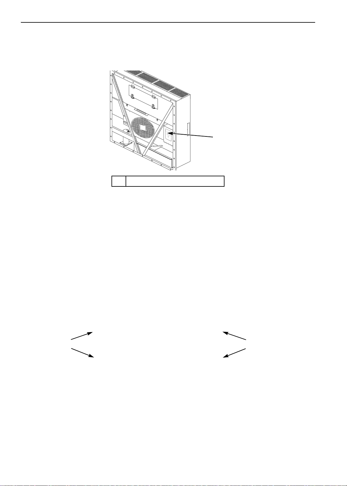
MP-4000 Controller
The MP-4000 is an advanced microprocessor controller that has been specially developed for the control
and monitoring of refrigeration units. See “Controller Description and Operating Chapter” for more
detailed information.
1. MP-4000 Controller
Figure 4: MP-4000 Controller
Power Module Fuses
The PM-4000 Power Module in the MAGNUM Plus unit uses Ultra Fast 20 amp fuses to protect the
power module and are not interchangeable with the MP3000 MRB fuses. The fuses from the MP3000
MRB must never be used in the PM 4000 Power Module.
Part number for a PM 4000 Power Module fuse (FF 20 amp 500v and black fuse holder) is:
P/N 419286 Fuse & Holder Blk MP4000
Part number for the MP3000 MRB fuse (F 20 amp 500V and red fuse holder) is:
P/N 419318 Fuse & Holder Red MP3000
Fuse and fuse holder will be sold together as a kit. Individual fuse and holder part number for the MP3000
will supersedes to the kit number once inventory is used up.
Figure 5: Power Module Fuses
24
Unit Description, Features & Options
AXA0428
AXA0427
Compressor Digital Control Valve
The MP-4000 controller pulses the Compressor Digital Control solenoid valve between open and closed
positions. This provides precise cooling capacity control. No pump down function or warm gas bypass
control is used in conjunction with the Compressor Digital Control valve. See the “General Theory of
Operation Chapter” for more detailed information.
Figure 6: Compressor Digital Control Solenoid Valve
Economizer Heat Exchange System
An economizer heat exchange system replaces the conventional heat exchanger. The economizer Heat
Exchange system subcools the liquid refrigerant before it reaches the evaporator expansion valve.
Subcooling liquid refrigerant increases the cooling efficiency and capacity of the evaporator. See the
“General Theory of Operation Chapter” for more detailed information.
Figure 7: Economizer Heat Exchanger
Temperature Sensors
Each sensor element is connected to a cable and packaged in a sealed stainless steel tube. The temperature
signal from the sensor is transmitted through the cable. PT.1000 type temperature sensors are used to
sense temperatures for the:
• Supply Air
• Return Air
• Evaporator Coil
• Condenser Coil
• Ambient Air
The compressor sensor is of Thermistor type and is located in the top cap of the compressor.
These sensors are field replaceable. Five sensor receptacles are provided; three USDA and one cargo
temperature.
25
Unit Description, Features & Options
1
BEN075
AXA0371
Fresh Air Exchange System
The fresh air exchange system removes harmful gases from containers carrying sensitive perishable
commodities. The fresh air vent is located above the control box. The fresh air vent is adjustable to
accommodate a variety of frozen and chilled load operating conditions.
1. Fresh Air Exchange Vent
Figure 8: Fresh Air Exchange Vent
Receiver Tank Sight Glass
The receiver tank contains a sight glass which has three small balls that indicate the level of refrigerant in
the tank for checking the refrigerant charge. A moisture indicator in the sight glass changes color to
indicate the level of moisture in the system.
1. Moisture Indicator:
Light Green = Dry
Yellow = Wet
2. Outer ring is color coded. Compare to
indicator.
Figure 9: Receiver Tank Sight Glass
Evaporator Fans
MAGNUM models are equipped with either 2 or 3 evaporator fans. All models feature 2-speed motors.
The evaporator fans operate continuously to circulate air inside the container . The evaporator fans operate
on:
• High and low speed for chilled cargo at setpoints of -9.9 C (14.1 F) and above
• Low speed for frozen cargo at setpoints of
-10 C (14 F) and below
26
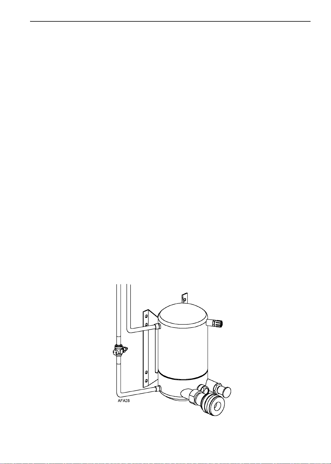
Unit Description, Features & Options
The evaporator fan low speed RPM is one-half the high speed RPM.
The controller determines evaporator fan motor speed based on the setpoint temperature and the
Economy mode setting.
NOTE: If Non-Optimized mode is on:
• Chill Loads: Evaporator fans operate on high speed
• Frozen Loads: Evaporator fans operate on low speed
NOTE: If optimized mode is on:
• Chill Loads: Evaporator fans operate on high and low speed - depending on the need for cooling.
• Frozen Loads: Evaporator fans operate on low speed and stops when there is no need for cooling.
Condenser Fan Control
The controller also uses a proportional-integral derivative algorithm to control the condenser temperature
and ensure a constant liquid pressure at the expansion valve. The condenser fan operates continuously in
high ambients. In low ambient conditions, the controller cycles the condenser fan on and off to maintain a
minimum condenser temperature. The controller maintains a minimum 30 C (86 F) condenser
temperature on Chill loads and a minimum 20 C (68 F) condenser temperature on Frozen loads.
USDA Cold Treatment Temperature Recording (standard)
The MP-4000 controller includes provisions for the use of three or four USDA sensors. These sensors
allow temperatures in various areas of the load to be monitored and recorded for United States
Department of Agriculture use in monitoring Cold Treatment shipments.
When USDA sensors are installed, the controller will automatically detect each sensor and activate data
logging. However, the USDA Type screen in the Configuration menu must be set to the correct sensor
setting and each USDA sensor must be calibrated to comply with USDA temperature recording
requirements.
Figure 10: Water-Cooled Condenser/Receiver Tank
27
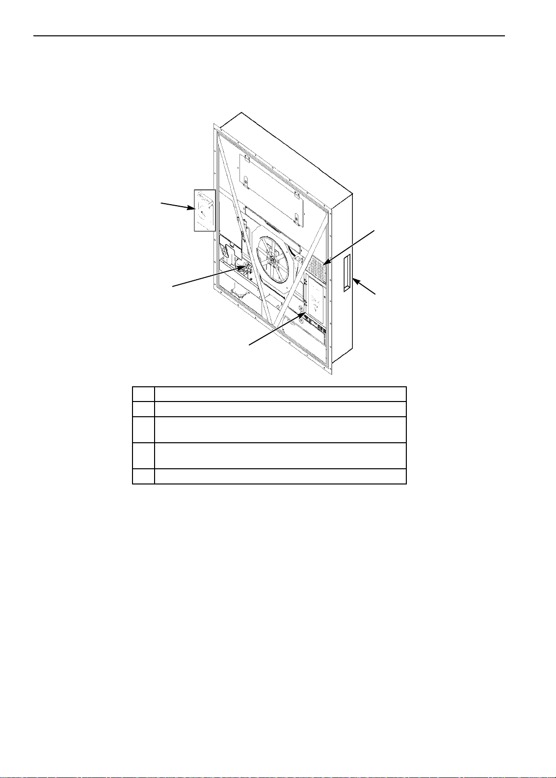
Unit Description, Features & Options
BEN061
1
5
3
4
2
Unit Options
This unit is available with several options that are listed in Figure 11. These options are specified when
placing the order. These options are briefly described on the following pages.
1. Electronic Chart Recorder (Optional)
2. AVL, AFAM, AFAM+ Options
USDA Sensor Receptacle (Access from Inside Container)
3.
(Optional)
Remote Monitor Modem for Power Line Communications
4.
(REFCON control modem inside Control Box) (Optional)
5. Suction/Discharge Pressure Transducer (Optional)
Figure 11: Optional Components
28
 Loading...