


pH 2000
Table of contents
 Loading...
Alpha pH 2000
Processor/Transmitter
pH / ORP

AQUAfast, Cahn, ionplus, KNIpHE, No Cal, ORION, perpHect, PerpHecT,
PerpHecTion, pHISA, pHuture, Pure Water, Sage, Sensing the Future, SensorLink,
ROSS, ROSS Ultra, Sure-Flow, Titrator PLUS and TURBO2 are registered
trademarks of Thermo Fisher.
1-888-pHAX-ION, A+, All in One, Aplus, AQUAsnap, AssuredAccuracy, AUTO-BAR,
AUTO-CAL, AUTO DISPENSER, Auto-ID, AUTO-LOG, AUTO-READ, AUTO-STIR,
Auto-Test, BOD AutoEZ, Cable-Free, CERTI-CAL, CISA, DataCOLLECT, DataPLUS,
digital LogR, DirectCal, DuraProbe, Environmental Product Authority, Extra
Easy/Extra Value, FAST QC, GAP, GLPcal, GLPcheck, GLPdoc, ISEasy, KAP,
LabConnect, LogR, Low Maintenance Triode, Minimum Stir Requirement, MSR,
NISS, One-Touch, One-Touch Calibration, One-Touch Measurement, Optimum
Results, Orion Star, Pentrode, pHuture MMS, pHuture Pentrode, pHuture Quatrode,
pHuture Triode, Quatrode, QuiKcheK, rf link, ROSS Resolution, SAOB, SMART
AVERAGING, Smart CheK, SMART STABILITY, Stacked, Star Navigator 21, Stat
Face, The Enhanced Lab, ThermaSense, Triode, TRIUMpH, Unbreakable pH,
Universal Access are trademarks of Thermo Fisher.
Guaranteed Success and The Technical Edge are service marks of Thermo Fisher.

Preface
This manual serves to explain the use of the Alpha pH 2000 series pH/ORP
controller/transmitter. The manual functions in two ways, firstly as a step by step
guide to help the user operate the instrument. Secondly, it serves as a handy
reference guide. This instruction manual is written to cover as many anticipated
applications of the Alpha pH 2000 pH/ORP controller/transmitter. If you have doubts
in the use of the instrument, please do not hesitate to contact your nearest Alpha
Authorised Distributor.
The information presented in this manual is subject to change without notice as
improvements are made, and does not represent a commitment on part of Thermo
Scientific.
Thermo Scientific cannot accept any responsibility for damage or malfunction of the
unit due to improper use of the instrument.
Copyright ©2003 All rights reserved.

Safety Information
The Alpha pH 2000 Controller/ Transmitter shall be installed and operated only in the
manner specified in the Instruction manual. Only skilled, trained or authorized person
should carry out installation, setup and operation of the instrument.
Before powering up the unit, make sure that power source it is connected to, is as
specified in the top label. Failure to do so may result in a permanent damage to the
unit.
The unit has live and exposed parts inside. If it has to be opened, make sure that the
power to the unit is off and disconnected.
The unit is Fuse protected. In the event the fuse has to be replaced, use only those
as specified in the manual.
The degree of protection against electric shock will be achieved only by observance
of the corresponding installation rules.

TABLE OF CONTENTS
1 INTRODUCTION.............................................................................................................................. 1
1.1 AT THE VERY BEGINNING.............................................................................................................. 1
1.2 INTENDED USE............................................................................................................................. 1
1.3 SAFETY INSTRUCTIONS................................................................................................................2
1.4 PUTTING OUT OF SERVICE / CORRECT DISPOSAL OF THE UNIT ........................................................2
2 PRODUCT DESCRIPTION.............................................................................................................. 3
2.1 DESCRIPTION OF UNIT.................................................................................................................. 3
2.2 MEASUREMENT AND CONTROL SYSTEM........................................................................................ 4
2.3 UNIT OVERVIEW.......................................................................................................................... 5
2.3.1 Display overview................................................................................................................6
2.3.2 Key functions ..................................................................................................................... 6
2.3.3 LED indicators.................................................................................................................... 7
2.3.4 Security codes ................................................................................................................... 7
2.3.5 Menu overview...................................................................................................................8
3 ASSEMBLY AND INSTALLATION.................................................................................................9
3.1 MOUNTING THE UNIT.................................................................................................................... 9
3.2 CONNECTION DIAGRAM ............................................................................................................. 11
4 NORMAL OPERATION.................................................................................................................14
4.1 MEASUREMENT MODE................................................................................................................ 14
5 CALIBRATION MODE................................................................................................................... 15
5.1 ENTERING CALIBRATION MODE................................................................................................... 15
5.2 PH CALIBRATION .......................................................................................................................16
5.3 ORP–MV CALIBRATION............................................................................................................. 17
5.4 ORP -% CALIBRATION............................................................................................................... 18
5.5 VIEW ACTUAL ZERO AND SLOPE.................................................................................................. 19
6 SET-UP MODE .............................................................................................................................. 20
6.1 ENTER SETUP MODE.................................................................................................................. 20
6.2 ELECTRODE OFFSET (OFS) SUB-FUNCTION................................................................................ 21
6.3 SETTING TEMPERATURE (SET OC) SUB-FUNCTION ....................................................................... 22
6.4 CONTROL RELAY A/CONTROL RELAY B (SP1/SP2) SUB-FUNCTION............................................. 23
6.5 CONTROLLER (CNTR) SUB-FUNCTION........................................................................................ 25
6.6 CURRENT OUTPUT 1 SUB-FUNCTION........................................................................................... 27
6.7 CURRENT OUTPUT 2 SUB-FUNCTION........................................................................................... 28
6.8 WASH RELAY (WASH) SUB-FUNCTION........................................................................................ 29
6.9 CONFIGURATION (CNFG) SUB-FUNCTION ...................................................................................30
6.10 CALIBRATION (CAL) SUB-FUNCTION ...........................................................................................32
7 RELAY MODES............................................................................................................................. 33
7.1 VIEW RELAY SET POINTS ............................................................................................................33
7.2 MANUAL RELAY MODE................................................................................................................ 34
8 TECHNICAL SPECIFICATIONS ................................................................................................... 35
8.1 GENERAL SPECIFICATION .......................................................................................................... 35
8.2 SPECIFICATIONS FOR WALL MOUNT VERSION............................................................................... 36
8.3 SPECIFICATIONS FOR PANEL MOUNT VERSION .............................................................................37
9 ACCESSORIES.............................................................................................................................38
9.1 REPLACEMENT UNIT.................................................................................................................. 38
9.2 ASSEMBLY ACCESSORIES.......................................................................................................... 38
10 GENERAL INFORMATION........................................................................................................ 39
10.1 WARRANTY...............................................................................................................................39
10.2 PACKAGING............................................................................................................................... 39

10.3
RETURN OF GOODS................................................................................................................... 39
10.4 GUIDELINES FOR RETURNING UNIT FOR REPAIR.......................................................................... 40
10.5 MAINTENANCE AND CLEANING.................................................................................................... 40
11 APPENDICES ............................................................................................................................ 41
11.1 APPENDIX 1 – UNIT FUSE AND JUMPER SETTINGS........................................................................ 41
11.2 APPENDIX 2 – PH BUFFER VALUES AT VARIOUS TEMPERATURES................................................... 43
11.3 APPENDIX 3 –SIMPLE EXPLANATION ON THE FUNCTION OF HYSTERISIS......................................... 44
11.4 APPENDIX 4 – GENERAL INSTRUCTIONS CONCERNING CONTROLLER SETTING .............................. 45
11.4.1 Control characteristic of Controllers used as limit value switch....................................... 45
11.4.2 Control characteristic of P-Controller as proportional controller...................................... 45
11.4.3 Control characteristic of PI-Controller as a proportional integral controller..................... 45
11.4.4 Controller signal of Pulse length Controllers ................................................................... 46
11.4.5 Controller signal of Pulse Frequency Controllers............................................................47
11.5 APPENDIX 5 – ABBREVIATIONS USED IN MENU DISPLAYS.............................................................. 48

1 INTRODUCTION
1.1 At the very beginning
We thank you for having purchased the Alpha pH 2000 pH/ORP Controller.
The construction of the pH/ORP Controller employs leading edge technology
and complies with safety regulations currently in force. Notwithstanding this,
improper use could lead to hazards for the user or a third-party, and/or
adverse effects on the plant or other equipment. Therefore, the operating
instructions must be read and understood by the persons involved before
work is started with the pH/ORP Transmitter.
This instruction manual identifies safety instructions and additional
information by means of the following symbols:
− This symbol draws attention to safety instructions and warnings of
potential danger which, if neglected, could result in injury to
persons and/or damage to property.
− This symbol identifies additional information and instructions
which, if neglected, could lead to inefficient operation and possible
loss of production.
The instruction manual must always be stored close at hand, in a place
accessible to all people working with the pH/ORP Controller.
If you have questions, which are not or insufficiently answered in this
instruction manual, please contact your Eutech Instruments supplier. They
will be glad to assist you.
1.2 Intended use
The Alpha pH 2000 pH/ORP Controller is intended solely for pH or ORP and
temperature measurement, as described in this instruction manual.
Any other use, or use not mentioned here, that is incompatible with the
technical specifications is deemed inappropriate. The operator is solely
responsible for any damage arising from such use.
Other prerequisites for appropriate use include:
– observing the instructions, notes and requirements set out in this
instruction manual.
– observing all local safety regulations concerning safety at work.
– observing all information and warnings in the documentation dealing with
the products used together with the transmitter (housings, sensors, etc.).
– observing the prescribed environmental and operational conditions.

1.3 Safety instructions
− The Alpha pH 2000 should be installed and operated only by
personnel familiar with the transmitter and who are qualified for
such work.
− A defective controller must neither be installed nor put into
service.
− The Alpha pH 2000 must only be operated under the specified
operating conditions (see section 8).
− The Alpha pH 2000 must not be repaired by the customer.
− The Alpha pH 2000 must only be opened to replace the unit fuse
or to set the jumper for Pt100/Pt1000 temperature sensor. This
work must be carried out only by personnel familiar with the
transmitter and who are qualified for such work. Make sure the
mains cable is separated from the power supply before opening
the unit.
− No modifications to the Alpha pH 2000 are allowed. The
manufacturer/supplier accepts no responsibility for damage
caused by unauthorised modifications. The risk is borne entirely
by the user.
1.4 Putting out of service / Correct disposal of the unit
Putting out of service
• First disconnect the unit from the mains, then undo all electrical
connections.
• Remove the unit from the wall / panel.
Correct disposal of the unit
When the transmitter is finally taken out of service, observe the local
environmental regulations for correct disposal or send the transmitter to your
local Eutech Instruments distributor, they will take care of proper disposal.

2 PRODUCT DESCRIPTION
2.1 Description of unit
The Alpha pH 2000 is used for measuring pH or ORP and temperature
values. The pH or ORP values can be measured using proportional or limit
control. The controller is available in two versions, one for panel mounting
and one for wall mounting in an enclosure. The controller can be used for
applications such as water treatment and monitoring, galvanicdecontamination, chemical processing, food processing, clean or wastewater
control and neutralization processes.
This controller has many user-friendly and safety features which include:
• Menu-driven program that simplifies set-up.
• Built-in non-volatile memory to ensure that calibration and other
information are not erased if power supply fails.
• Push-button for calibration and electrode offset adjustment from the
keypad.
• Automatic temperature compensation (ATC).
• Manual temperature compensation setting without the ATC probe, with
independent setting for calibration and process temperature.
• Two galvanically isolated current outputs 0/4...20mA
• 0 to 1999 seconds time delay adjustment on all relays – minimizes false
alarms.
• Separately adjustable high and low set-point hysteresis (dead bands)
prevent chattering of relays around the set points.
• Asymmetrical/symmetrical input for pH/ORP mode of operation.
• Three control modes: limit controller, P controller and PI controller (P/PI
controller as pulse length or pulse frequency).
• Large dual display LCD for easy reading with clear multiple annunciators,
alarm status, operational and error messages.
• Two switching contacts as set-point relays.
• Separate alarm relay alerting you to set point limits exceeded for a certain
time and if the Pt100/Pt1000 wires are broken or disconnected during the
ATC function.
• Wash relay.
• Hold function to freeze output current (0/4...20mA) and release control
relays.
• LED indicators signal control activities to visually monitor transmitter status
from a distance.
• Protection against electromagnetic interference.
• Back lit and UV light protected LC display
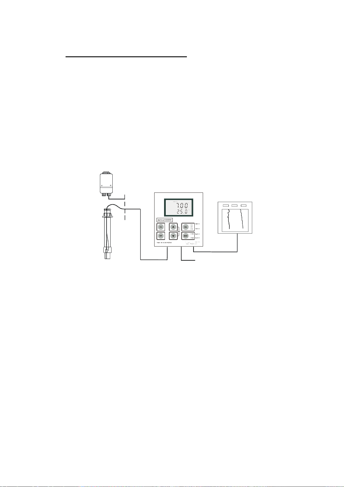
2.2 Measurement and Control System
A typical measurement system consists of:
• a pH/ORP process controller
• a pH/ORP combination electrode with integrated or separate temperature
sensor Pt 100/1000,
• an appropriate pH or ORP measurement cable
• an immersion, flow or process assembly with or without a potential
matching pin (PMP)
• a final control element such as pump or valve
• a chart recorder
Flow Assembly
Process Assembly
with Electrode
MeasurementCable
pH Controller
Power Mains
(220/110VAC)
Chart Recorder
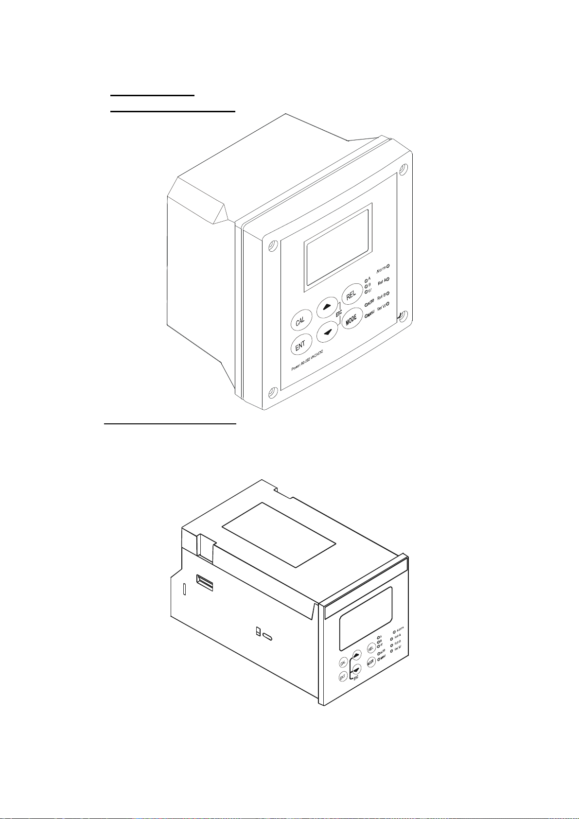
2.3 Unit Overview
Wall mounting version
Panel mounting version
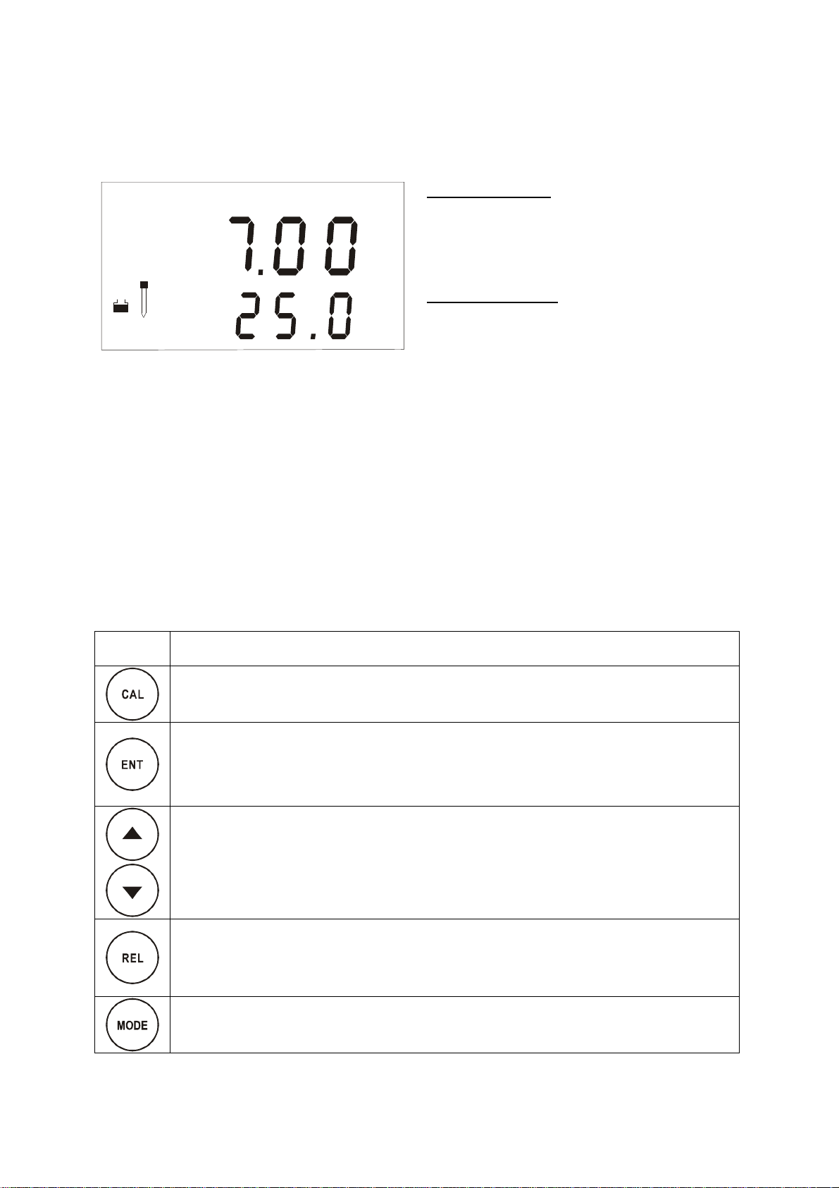
2.3.1 Display overview
The LC display shows two alpha-numerical fields for parameters and measured
values as well as various mode and status indicators.
SETUP
ready
HOLD
err
s
MEAS
CAL
H%
P
O
C
h
p
atc
Mode indicators:
v
m
– MEAS: Measurement mode
– SETUP: Set-up mode
– CAL: Calibration mode
O
f
Status indicators:
– READY: Visible after successful
calibration
– HOLD: Unit in “HOLD” mode
– ATC: Visible in ATC (Automatic
Temperature Compensation) mode. Not
visible in the Manual temperature
compensation mode. “ATC” flashes if the
temperature probe is faulty in its ATC
mode
– ERR: Error indicator
– S: Visible in symmetrical measurement
mode
2.3.2 Key functions
Key
Description
– Enter Calibration mode (requires access code)
– Enter Set-up mode (requires access code)
– Access sub functions (parameters) within a function group of Set-up mode
– Confirm (store) set-up parameters and numerical values
– Start calibration in Calibration mode
– Select function group in the Set-up mode.
– Set parameters and numerical values(if key is pressed continuously, the
setting speed increases)
– Control the relays in MANUAL relay operation
– Returns to “Measurement mode” when both keys are pressed simultaneously
– Display limit values for SP1 and SP2 and settings for wash contact in AUTO
relay operation
– Toggle between RELAY A, RELAY B or Wash relay in MANUAL relay
operation
– Switch from AUTO to MANUAL relay operation (requires access code)
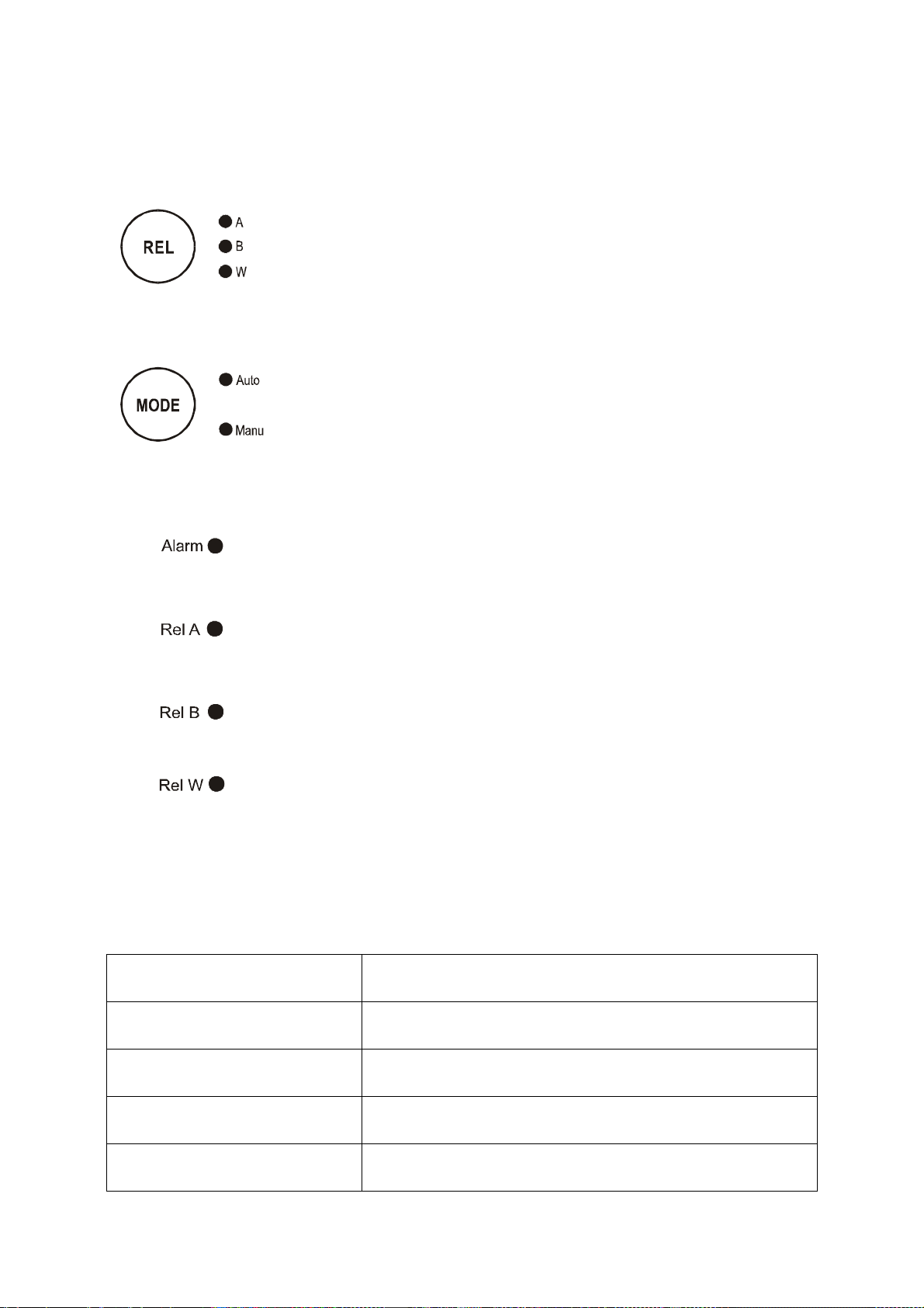
LED indicators
Relay indicators
If REL key is pressed the LED (A, B or W) indicates to which
Relay (A, B or Wash) the displayed limit values refer.
Relay mode indicators
Auto LED lights if relay operation is set to automatic mode.
Manu LED lights if relay operation is set to manual mode.
Relay status indicators
This LED lights if limit value is exceeded or the ATC probe
fails.
This LED lights green if measured value is within the limit for
Relay A or lights red if measured value exceeds limit.
This LED lights green if measured value is within the limit for
Relay B or lights red if measured value exceeds limit.
This LED lights if cleaning cycle is on.
2.3.3 Security codes
The access to Calibration mode, Setup mode and Manual relay operation
mode is protected with security codes. The security codes are set at the
factory and cannot be changed by the user. The following security codes are
used:
Security code Mode Description
000 View only mode to view actual settings
11 Calibration mode to start calibration
22 Setup mode to configure parameters
22 Manual relay operation to switch relay operation mode
from automatic to manual
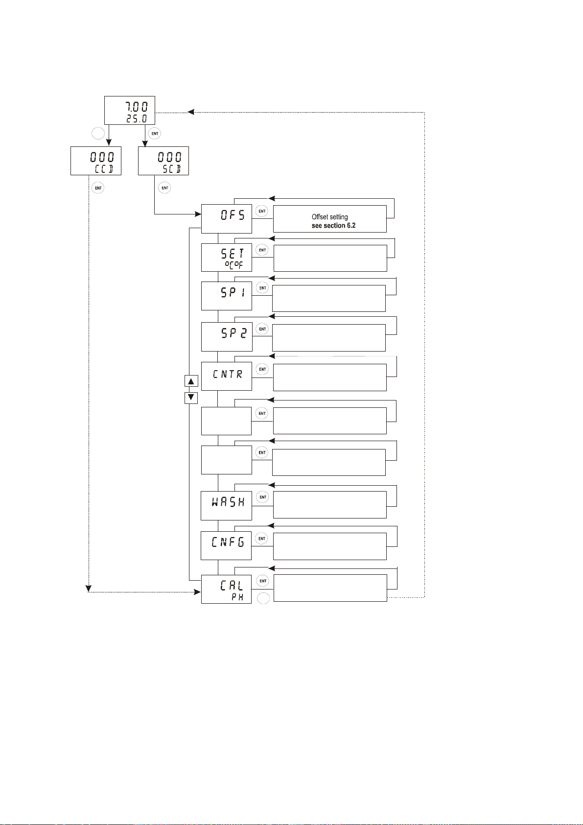
Menu overview
MEAS
CAL
P
O
H
C
*CCD “000”= Check calibration parameters (View only mode)
ENTERENTER
SETUP
HOLD
SETUP
HOLD
CCD “11” = Calibration mode
** SCD “000” = Check setup parameters (View only mode)
SCD “22” = Setup mode
Temperature settings
see section 6.3
SETUP
HOLD
Relay A (set poi nt 1) settings
see section 6.4
SETUP
HOLD
Relay B (set point 2) settings
see section 6.4
SETUP
HOLD
SETUP
HOLD
cur.1
SETUP
HOLD
cur.2
SETUP
HOLD
SETUP
HOLD
SETUP
HOLD
Controller settings
see section 6.5
Current output 1 sett ing s
see section 6.6
Current output 2 sett ing s
see section 6.7
Wash contact settings
see section 6.8
Unit settings
see section 6.9
Calibration
CAL
see sec tio n 5
3 ASSEMBLY AND INST ALLATION
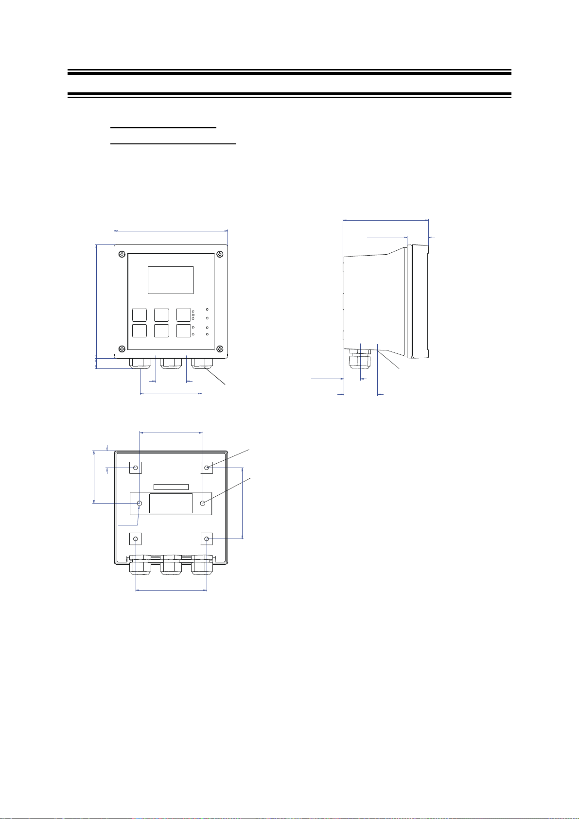
3.1 Mounting the unit
Wall Mounting Version
144 [5.67]
144 [5.67]
111.50 [4.39]
27.5 [1.08]
approx. 14 [.55]
66.5 [2.62]
39 [1.54]
78 [3.07]
80 [3.15]
21.5 [.85]
6 [.24]
90 [3.54]
Pg13.5 (3 pcs.)
Holes for post
mounting (4X)
Holes for wall
mounting (2X)
90 [3.54]
24 [.94]
57.8[2.28]
Unit:
MM [INCH]
For Pg13.5 cable glands
Transmitter housing for wall mounting: protection class IP 65
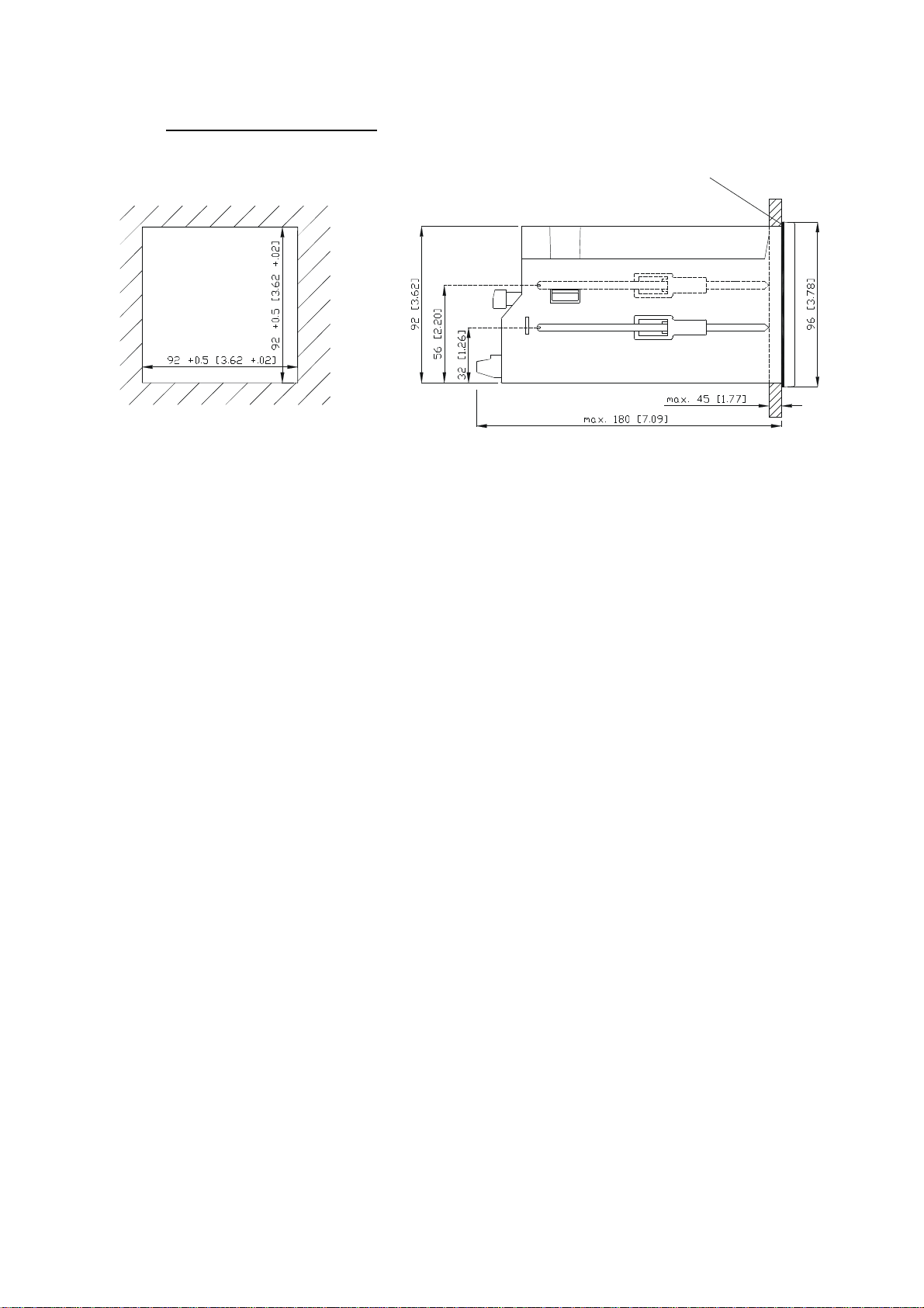
Panel mounting version
Flat gasket 1mm [.04]
(to be inserted by customer)
Panel cut out
UNIT: MM [INCH]
Transmitter housing for panel mounting: protection class IP 54 (front), IP 40 (housing)
Loading...