


Alpha DO 500
Transmitter
Dissolved Oxygen
AQUAfast, Cahn, ionplus, KNIpHE, No Cal, ORION, perpHect, PerpHecT, PerpHecTion, pHISA, pHuture, Pure Water, Sage, Sensing the Future, SensorLink, ROSS, ROSS Ultra, Sure-Flow, Titrator PLUS and TURBO2 are registered trademarks of Thermo Fisher.
1-888-pHAX-ION, A+, All in One, Aplus, AQUAsnap, AssuredAccuracy, AUTO-BAR, AUTOCAL, AUTO DISPENSER, Auto-ID, AUTO-LOG, AUTO-READ, AUTO-STIR, Auto-Test, BOD AutoEZ, Cable-Free, CERTI-CAL, CISA, DataCOLLECT, DataPLUS, digital LogR, DirectCal, DuraProbe, Environmental Product Authority, Extra Easy/Extra Value, FAST QC, GAP, GLPcal, GLPcheck, GLPdoc, ISEasy, KAP, LabConnect, LogR, Low Maintenance Triode, Minimum Stir Requirement, MSR, NISS, One-Touch, One-Touch Calibration, One-Touch Measurement, Optimum Results, Orion Star, Pentrode, pHuture MMS, pHuture Pentrode, pHuture Quatrode, pHuture Triode, Quatrode, QuiKcheK, rf link, ROSS Resolution, SAOB, SMART AVERAGING, Smart CheK, SMART STABILITY, Stacked, Star Navigator 21, Stat Face, The Enhanced Lab, ThermaSense, Triode, TRIUMpH, Unbreakable pH, Universal Access are trademarks of Thermo Fisher.
Guaranteed Success and The Technical Edge are service marks of Thermo Fisher.

Preface
This manual serves to explain the use of the Alpha DO 500 transmitter. It functions in two ways, firstly as a step by step guide to help you to operate the transmitter. Secondly, it serves as a handy reference guide. It is written to cover as many anticipated applications of the transmitter as possible. If there are doubts in the use of the transmitter, please do not hesitate to contact the nearest Authorized Distributor.
Thermo Scientific will not accept any responsibility for damage or malfunction to the transmitter caused by improper use of the instrument.
Remember to fill in the guarantee card and mail it back to your authorized distributor.
The information presented in this manual is subject to change without notice as improvements are made, and does not represent a commitment on the part of Thermo Scientific.
Copyright 2009 All rights reserved.

Table of Contents
1. Introduction ........................................................................................................... |
1 |
|
1.1 |
Before You Begin ................................................................................................................... |
1 |
1.2 |
Intended Use.......................................................................................................................... |
1 |
1.3 |
Safety Instructions.................................................................................................................. |
2 |
1.4 |
Taking Out of Service / Correct Disposal of the Unit ............................................................. |
2 |
2. Getting Started ...................................................................................................... |
3 |
|
2.1 |
Description of Instrument ....................................................................................................... |
3 |
Power Supply Requirements (SL2 Position) ................................................................................... |
3 |
|
2.2 |
Measurement and Control System......................................................................................... |
4 |
2.3 |
Connecting Peripherals.......................................................................................................... |
5 |
|
2.3.1 Connection Terminals.................................................................................................... |
5 |
|
2.3.2 Connecting Dissolved Oxygen Electrode...................................................................... |
6 |
|
2.3.3 Connecting Temperature Probe .................................................................................... |
6 |
2.4 |
Installation .............................................................................................................................. |
7 |
|
2.4.1 Mechanical Dimensions................................................................................................. |
7 |
|
2.4.2 Wall Mount..................................................................................................................... |
7 |
|
2.4.3 Panel Mount................................................................................................................... |
8 |
2.5 |
Display & Keypad................................................................................................................... |
9 |
|
2.5.1 Display Overview........................................................................................................... |
9 |
|
2.5.2 Key Functions.............................................................................................................. |
10 |
3. Normal Operation ................................................................................................ |
11 |
|
3.1 |
Measurement mode ............................................................................................................. |
11 |
3.2 |
Menu Overview .................................................................................................................... |
12 |
4. Calibration Mode ................................................................................................. |
13 |
|
4.1 |
Entering Calibration Mode.................................................................................................... |
13 |
4.2 |
Calibration in mg/l or ppm of Oxygen................................................................................... |
14 |
|
4.2.1 1-Point Calibration....................................................................................................... |
14 |
|
4.2.2 2-Point Calibration....................................................................................................... |
15 |
4.3 |
Calibration in% Saturation of Oxygen .................................................................................. |
17 |
|
4.3.1 1-Point Calibration....................................................................................................... |
17 |
|
4.3.2 2-Point Calibration:...................................................................................................... |
18 |
5. Setup Mode.......................................................................................................... |
20 |
|
5.1 |
Enter Setup mode ................................................................................................................ |
20 |
5.2 |
Configuration Settings.......................................................................................................... |
21 |
5.3 |
Offset Settings...................................................................................................................... |
23 |
5.4 |
Temperature Settings........................................................................................................... |
25 |
5.5 |
Range Settings..................................................................................................................... |
27 |
5.6 |
Hold Settings........................................................................................................................ |
28 |
5.7 |
Out of Range Settings.......................................................................................................... |
29 |
5.8 |
Viewing Calibration Point ..................................................................................................... |
30 |
5.9 |
Viewing Electrode Condition ................................................................................................ |
31 |
5.10 |
Resetting .............................................................................................................................. |
32 |
6. Technical Specifications..................................................................................... |
33 |
|
7. List of Accessories ............................................................................................. |
35 |
|
7.1 |
Thermo Scientific.................................................................................................................. |
35 |
7.2 |
Eutech Instruments .............................................................................................................. |
36 |
8. |
Troubleshooting.................................................................................................. |
37 |
||
9. |
General Information ............................................................................................ |
38 |
||
|
9.1 |
Warranty............................................................................................................................... |
|
38 |
|
9.2 |
Return of Goods................................................................................................................... |
38 |
|
|
9.3 |
Guidelines for Returning Unit for Repair .............................................................................. |
38 |
|
|
9.4 |
Maintenance and Cleaning .................................................................................................. |
38 |
|
10. Appendices ....................................................................................................... |
|
39 |
||
|
10.1 |
Appendix 1 |
– Salinity vs. Temperature (@ 760mmHg)........................................................ |
39 |
|
10.2 |
Appendix 2 |
– Abbreviations Used in LCD............................................................................ |
40 |

Instruction Manual |
Alpha DO 500 |
1.Introduction
1.1 Before You Begin
We thank you for purchasing the Alpha DO 500 Transmitter.
The construction of the Alpha DO 500 Transmitter employs leading edge technology and complies with safety regulations currently in force. Notwithstanding this, improper use could lead to hazards for the user or a third-party, and/or adverse effects on the plant or other equipment. Therefore, the operating instructions must be read and understood by the persons involved before work is started with the Alpha DO 500 Transmitter.
The instruction manual must always be stored close at hand, in a place accessible to all people working with the Alpha DO 500 Transmitter.
If you have questions, which are not or insufficiently answered in this instruction manual, please contact your authorized supplier. They will be glad to assist you.
1.2 Intended Use
Alpha DO 500 Transmitters are intended solely for dissolved oxygen (DO) and temperature measurement, as described in this instruction manual.
Any other use, or use not mentioned here, that is incompatible with the technical specifications is deemed inappropriate. The operator is solely responsible for any damage arising from such use.
Other prerequisites for appropriate use include:
–Comply with the instructions, notes and requirements set out in this instruction manual.
–Comply with all local safety regulations concerning safety at work.
–Comply with all information and warnings in the documentation dealing with the products used together with the Alpha DO 500 Transmitter (housings, sensors, etc.).
–Comply with local environmental and operational conditions.
1

Instruction Manual |
Alpha DO 500 |
1.3Safety Instructions
-The Alpha DO 500 Transmitter should be installed and operated only by personnel familiar with the instrument and who are qualified for such work.
-A defective Transmitter must neither be installed nor put into service.
-The Alpha DO 500 Transmitter must only be operated under the specified operating conditions (see section 5.9).
-The Alpha DO 500 Transmitter must not be repaired by the customer.
-No modifications to the Alpha DO 500 Transmitter are allowed. The manufacturer/supplier accepts no responsibility for damage caused by unauthorized modifications. The risk is borne entirely by the user.
1.4Taking Out of Service / Correct Disposal of the Unit
Taking out of Service
First disconnect the unit from the power supply and then undo all electrical connections.
Remove the unit from the wall / panel.
Correct Disposal of the Instrument
When the DO Transmitter is permanently taken out of service, obey the local environmental regulations for correct disposal or send the instrument to your local distributor, they will take care of proper disposal.
2

Instruction Manual |
Alpha DO 500 |
2.Getting Started
2.1 Description of Instrument
The Thermo Scientific Alpha DO 500 Transmitter is used for measuring dissolved oxygen and temperature values. The dissolved oxygen values can be measured using industrial dissolved oxygen sensors. The temperature values can be measured using 2-wire or 3-wire Pt100 sensors. The DO Transmitter can be used for applications such as water treatment and monitoring, galvanic-decontamination, chemical processing, food processing, clean or wastewater control and neutralization processes.
The Alpha DO 500 Transmitter has many user-friendly and safety features which include:
Push-button keypad for calibration and setup
Built-in non-volatile memory to ensure that calibration and other information are not erased if power supply fails
Menu-driven program that simplifies setup
Automatic temperature compensation (ATC)
Manual temperature compensation setting without the ATC probe, with independent setting for calibration and process temperature
Large dual display LCD for easy reading with clear multiple annunciators, operational mode indicators and error indicators.
Galvanically isolated current output of 4 to 20mA
Hold function to freeze output current (22mA)
Out of range current indication (3.8mA)
Protection against electromagnetic interference
Power Supply Requirements (SL2 Position)
This transmitter requires a 12 to 24V DC power supply. Other Transmitters and/or a chart recorder may be connected in series.
1.Insert positive loop wire from power supply to pin 1, tighten screw.
2.Insert negative loop wire to pin 2, tighten screw. This wire may be linked to a chart recorder or to negative terminal of power supply.
1 
Alpha pH500 |
Power Supply |
2
Chart recorder
3
Instruction Manual |
Alpha DO 500 |
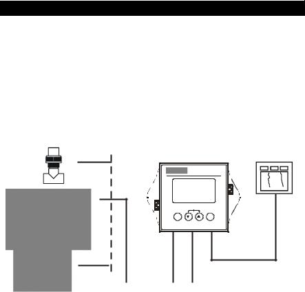
2.2 Measurement and Control System
A typical measurement system consists of:
A Alpha DO 500 Transmitter
A dissolved oxygen sensor with integrated or separate Pt100 temperature sensor
An appropriate measurement cable
An immersion, flow or process assembly
A chart recorder
Alpha DO500 Transmitter |
Chart Recorder |
|
|
Alpha DO500 |
|
ESC |
CAL |
ENT |
2-wire Dissolved Oxygen Transmitter |
|
4 - 20 mA
Housing and |
|
|
|
|
Power Adaptor |
Measurement Cable |
|
||||
|
(12 to 24 V DC) |
||||
Sensors |
|
|
|
|
|
4
Instruction Manual |
Alpha DO 500 |
2.3 Connecting Peripherals
2.3.1Connection Terminals Remove Back Cover:
Remove the screws from the four corners at the back of the DO Transmitter. Remove the back cover. The connectors are exposed on the back PCBA as shown in the Figure 1 below.
Connectors:
SL2 – 12 to 24 V DC power
SL1 – Dissolved Oxygen electrode & Temperature probe connections (wiring has to be done in the detachable connector
SL2
SL1
Figure 1: Outer Side of Back PCBA
SL1 Connections
1.DO Input, +ve terminal
2.DO Input, -ve terminal
3.No Connection
4.No Connection
5.PT100 Compensate
(Short to pin 6 for 2-wire RTD)
6.PT100 Sense
7.PT100 Ground
8.No Connection
SL 2 Connections
1.DC Power Supply +ve terminal
2.DC Power Supply –ve terminal
3.No Connection
5
Instruction Manual |
Alpha DO 500 |
2.3.2 Connecting Dissolved Oxygen Electrode
Refer the instruction sheet that comes with your Dissolve Oxygen electrode to identify polarity (+ve and –ve) of DO wires.
1.Connect DO +ve wire to Pin 1 of SL1 connector
2.Connect DO -ve wire to Pin 2 of SL1 connector
2.3.3Connecting Temperature Probe
For Automatic Temperature Compensated (ATC) readings, a 100 Pt RTD temperature probe (2-wire or 3-wire) can be connected to the Transmitter.
3-Wire Probe:
1.Connect PT100 compensate wire to Pin 5 of SL1 connector
2.Connect PT100 sense wire to Pin 6 of SL1 connector
3.Connect PT100 GND wire to Pin 7 of SL1 connector
2-Wire Probe:
1.Short Pin 5 & 6 of SL1 connector using a small piece of wire.
2.Connect PT100 sense wire to Pin 6 of SL1 connector
3.Connect PT100 GND wire to Pin 7 of SL1 connector
6

Instruction Manual |
Alpha DO 500 |
2.4 Installation
2.4.1 Mechanical Dimensions
|
Alpha DO 500 |
|
ESC |
CAL |
ENT |
2-wire Dissolved Oxygen Transmitter |
|
2.4.2 Wall Mount
1 |
Pierce through holes at |
|
both sides |


 2
2


 Cover
Cover the
the
 catch
catch
 slots at both sides with overlays
7
Instruction Manual |
Alpha DO 500 |
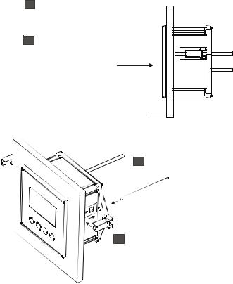
2.4.3 Panel Mount
1
2
Prepare panel cut-out of
92.0 mm X 92.0 mm
Remove back cover of DO Transmitter and slide it through panel cut-out
Gasket 
Panel

 Panel
Panel
4 Insert threaded rods through catch
until DO Transmitter is held against panel
3 Attach catch to both sides of DO Transmitter
8
Instruction Manual |
Alpha DO 500 |
2.5 Display & Keypad
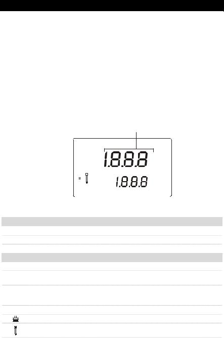
2.5.1 Display Overview
The Liquid Crystal Display (LCD) of the Alpha DO 500 Transmitter has two alpha-numerical displays (Upper and a Lower).
Upper display: Measured dissolved oxygen reading (in % saturation or ppm or mg/l) is displayed when the Transmitter is in normal operation (measurement) mode.
Lower display: Measured temperature value is displayed when the Transmitter is in normal operation (measurement) mode. In Calibration mode, calibration points are displayed here.
The two displays indicate function names, options & settings in Setup mode. Refer ‘Appendix 2 – Abbreviations Used in LCD’ for more details.
The LCD also consists of various mode indicators, status annunciators and unit of measurement indicators.
Upper Display
SETUP MEAS CAL
%
READY-
HOLD
K= ppm mg/l
|
|
|
- |
|
|
°C |
|
|
|
ERR |
|
|
|
|
|
|
|
|
|
ATC |
|
|
|
|
|
|
|
|
|
|
|
|
|
|
|
|
|
|
|
|
|
|
|
|
|
Lower Display |
||
Mode Indicators
MEAS Measurement mode (Refer Section 3.1)
SETUP Setup mode (Refer Section 5)
CAL Calibration mode (Refer Section 4)
Status Annunciators
READY Appears when the reading is stable
HOLD Appears in Setup mode and Calibration mode to indicate that the relay function is frozen
ATC Appears when Automatic Temperature Compensation (ATC) is enabled.
Not visible when Manual Temperature Compensation (MTC) is enabled. Flashes if the temperature probe is faulty in its ATC mode. (Refer Section 5.4)
ERR Appears when an error occurs
Buffer annunciator. Appears in calibration mode or viewing calibrated point
Electrode annunciator. Appears when viewing electrode properties or during calibration error
9
 Loading...