

50 L HyPerforma DynaDrive Single-Use
Bioreactor Quick Start Guide
This Guide provides a brief overview of setting up the Thermo Scientific™ HyPerforma™ DynaDrive Single-Use Bioreactor (S.U.B.)
system. For more detailed information about the DynaDrive S.U.B., refer to the 50 L HyPerforma DynaDrive S.U.B. User’s Guide
(DOC0090).
Warnings and safety
Hazardous voltage inside—risk of electrical
shock. Service should be provided by certified
personnel only.
Hot surface—do not touch.
The heating jacket is designed to heat the inner
vessel wall. Contact with surfaces may cause
burns.
Pinch hazard. Use caution when opening/
closing the door, securing the BPC to the
top and bottom ports in the tank, and during
operation of the DynaDrive S.U.B.
Burst hazard—air under pressure. Do not
exceed 30 mbar (0.5 psi) BPC pressure. Do
not exceed 34 mbar (5 psi) inlet pressure.
Ensure that the vent filter is correctly positioned
and working properly.
Tipping hazard. The vessel should only
be moved by pushing using the provided
handles or at the mid-point of the vessel.
If pulled or moved too quickly, the vessel can
tip, potentially leading to damage to equipment
or injury to personnel. To reduce the risk of
tipping, the vessel should only be moved
slowly over smooth, flat surfaces by at least
two qualified personnel. During movement, any
locking feet should be retracted, and casters
should be in the unlocked position. The vessel
should not be moved by pulling of any kind.
The Thermo Scientific HyPerforma
DynaDrive S.U.B. may not be installed in
a potentially explosive atmosphere as set
forth in the applicable EU ATEX Directive.
It is the responsibility of the end user to review
and understand the potential dangers listed in
the ATEX 2014/34/EU guidelines.
Static electricity may build up in BPCs.
• BioProcess Containers (BPCs) may act
as insulators for electrostatic charge. If
electrostatic charge is transferred to a BPC,
the charge may be stored in the BPC and/or
the product inside. This phenomena varies
by product and use; therefore, it is the sole
responsibility of the end user to ensure a
hazard assessment is conducted and the
risk of electrostatic shock is eliminated.
• Where applicable, a product contact
stainless steel coupler may be grounded
to the frame to dissipate electrostatic
buildup from the material within a BPC. It
is good practice to dissipate electrostatic
buildup by grounding all BPCs prior to
coming in contact with them. When working
with BPCs, the use of nonconductive
materials, such as nonconductive gloves, is
recommended.
Rotating parts—entanglement hazard.
Rotating and moving parts can cause injury.
Keep hands away from moving parts during
operation. Do not operate this equipment unless
the supplied guarding is in place and properly
functioning. It is the responsibility of the end
user to assess this equipment and ensure that
equipment and safeguards are in good working
condition, and that all operators are trained and
aware of entanglement hazards and associated
protective devices, such as hazard signs and
guarding.
Follow lockout/tagout procedures. To
prevent injury, when servicing equipment, use
your company’s lockout/tagout procedures
to isolate electrical, mechanical, pneumatic,
hydraulic, chemical, thermal, gravitational, or
any other potential energy and protect workers
from the release of hazardous energy.
Use caution with hazardous chemicals or
materials. Personnel servicing equipment
need to know the hazards of any chemicals
or materials that may be present on or in the
equipment. Use general hazard communication
techniques such as Safety Data Sheets, labels,
and pictograms to communicate any hazards.
Note that this machine does not produce or
process any toxic, corrosive, flammable, and
explosive substances, nor uses any additives,
compounds of mercury, cadmium, chromium,
asbestos, CFC, or HCFC for machine
maintenance purposes.
Use a properly configured and approved
power cord for voltage supply in your
facility.
Read and understand the user’s guide
before operating the equipment. The
HyPerforma DynaDrive S.U.B. is designed to
be operated under traditional eukaryotic cell
culture conditions. A general understanding
of bioreactor systems and their operation is
important prior to using the system for the first
time. Read and understand this user’s guide
before operating; failure to do so could result
in injury and potential loss of product. Only
trained operators should be allowed to operate
the equipment.
For complete warnings, safety, and warranty information,
refer to the 50 L HyPerforma DynaDrive S.U.B. User’s
Guide.
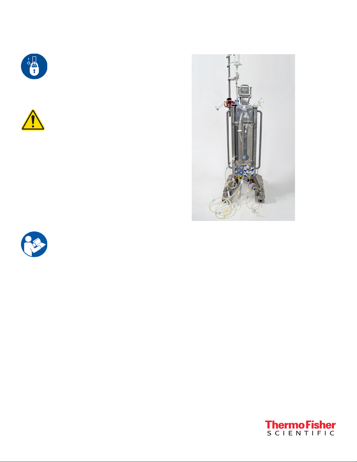
Figure 1. Front view of the 50 L DynaDrive S.U.B.
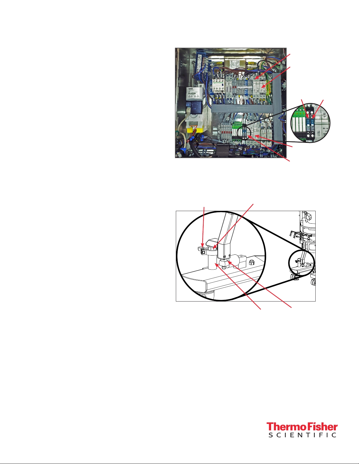
Electrical preparation (for systems with the
optional Thermo Scientific E-Box)
1. Using a flat-head screwdriver, open the E-Box
and locate the breakers for the pressure sensor,
continuous power outlets non E-stoppable (2), and
continuous power outlets E-stoppable (2) (Figure
2 on the following page). These breakers should
be in the “on” position (“up” position or pressed in,
depending on the breaker type) during operation.
For electrical schematics, please refer to the ETP,
which is provided on a USB drive.
Unpacking the system
First, inspect the packaging for damage. Call your Thermo
Scientific sales representative if any damage is present.
Use the instructions provided in the 50 L HyPerforma
DynaDrive S.U.B. Unpacking Guide (DOC0149) to unpack
your S.U.B. unit from the shipping crate.
2
2. Close the E-Box and lock the panel using a
A
flat-head screwdriver before continuing.
3. Connect all electrical plugs to facility power. Refer
to hardware/electrical labels and schematics to
ensure proper electrical voltage is connected to
the DynaDrive S.U.B. Note: The yellow plug and
receptacle are for 120 VAC, and the blue plug and
receptacle are for 240 VAC S.U.B.s.
Unlocking load cells
Figure 3 illustrates the location and components of load
cells on a 50 L DynaDrive S.U.B.
All load cells must be fully locked down in order to
move the DynaDrive S.U.B. For DynaDrive S.U.B.
hardware units purchased with factory-installed load
cells, the load cells are shipped in the locked position
(threaded up) for equipment protection.
1. To unlock the load cells (after the system is in its
final location), remove and discard the delrin slip
ring if it is present. Remove the tri-clamp.
Figure 2. DynaDrive S.U.B. E-Box interior.
38.1 mm (1.5 in.)
Tri-clamp
Lockout nut
VFD breaker
Main power
breaker
Temp.
display
breaker
E-Stop power
breaker
Continuous power
breaker
Pressure
sensor
breaker
2. Loosen the lockout nut, using an adjustable or
1.25 in. wrench (not supplied), until the nut is tight
against the base or leg of the S.U.B. Repeat this
process for each load cell until all of the lockout
nuts are disengaged from the lockout posts. Do
not reinstall the tri-clamp.
3. At this point, the DynaDrive S.U.B. hardware is
ready to be prepared for BPC loading.
Leveling and connecting the system
All manual movements of the DynaDrive S.U.B.
hardware should be over smooth surfaces, with the
S.U.B. empty and disconnected from all power and
gas/feed sources. All load cells must be fully locked
down in order to move a S.U.B.
1. Verify that the facility electrical supplies are
sufficient to support the power requirements of the
DynaDrive S.U.B. and ancillary components, such
as controllers or pumps.
Figure 3. Load cell schematic.
Lockout
post
Delrin slip
ring
3

2. Locate the outer support container in the area for the
cell culture run.
Note: Refer to the TCU manufacturer’s guidelines for
detailed TCU setup information.
3. When monitoring the batch volume, the unit may be
placed on a weight scale if load cells are not part of
the system. Other methods may be used to measure
all incoming and outgoing liquids.
4. Level the platform by disabling the swivel casters on
the bottom of the outer support container. This is
accomplished by threading the leveling feet (at the
center of each caster) to the floor.
5. Verify the location of the pH/DO controllers and
ensure that the cable and tubing lengths are
sufficient.
6. Verify that the main power is off and the emergency
stop (E-Stop) is pulled out. Note: The E-Stop
disconnects all power to the system. An alarm buzzer
will sound when the E-Stop is activated.
7. Verify that the main motor power switch is in the “off”
position.
8. Connect all electrical plugs to facility power. Refer to
hardware/electrical labels and schematics to ensure
proper electrical voltage is connected to the S.U.B.
The main power switch can now be turned on.
9. Connect the inlet and outlet lines from the
temperature control unit (TCU) quick-connects to
the jacket (Figure 4). The inlet is typically on the right
side if you are facing the connectors; refer to the
permanent labels on the inlet and outlet lines.
10. Use the tri-clamp fitting to attach the water jacket
inlet/outlet ports to the bottom of the outer support
container (Figure 5).
Figure 5. Removing the tri-clamp and attaching the fitting.
Note: Figure 5 shows the tri-clamp fitting and inlet/outlet
ports on a standard HyPerforma S.U.B. The location and
process is the same for DynaDrive S.U.B.s.
Loading the BPC
Use the following information to install and set up the BPC.
Checkpoints prior to BPC loading
9 A 50 L DynaDrive BPC is being used for the
50 L outer support container.
9 The outer support container is stationary, with the
casters locked in place.
9 Two operators are available for BPC loading.
9 The Thermo Scientific BPC Unpacking and Inspection
Guide (DOC0021) has been reviewed for information on
handling, transporting, and storing BPCs.
Figure 4. Attaching water jacket port using a
tri-clamp.
4
1. Open the door on the bioreactor outer support
container.
2. Use a safety cutter to slit the taped sides/ends of the
cardboard box in which the BPC is shipped.

3. Lift the lid off the top of the box, then lift the
cardboard tray out of the box and set it on a flat,
raised surface (Figure 6).
6. Hold the exposed end of the BPC in place and use your
other hand to pull the outer polybag away from the BPC
(Figure 9).
Figure 6. Removing lid and setting the tray on a flat sur face.
4. Use a safety cutter to cut the plastic cling wrap
securing the BPC to the cardboard tray. Remove the
cling wrap and undo the flaps that are folded on the
underside of the tray (Figure 7).
Figure 7. Undoing flaps on bottom of tray.
5. Use a safety cutter to carefully open the outer
polybag (Figure 8). Take care to not damage the
BPC.
Figure 9. Pulling the outer polybag away
from the BPC.
7. The BPC is also protected by an inner polybag. Use a
safety cutter to open the inner polybag, taking care to
not damage the BPC, and remove the polybag while
holding the BPC in place.
8. Push the blue and black button on the hub cover located
at the top of the S.U.B. to unlock it (Figure 10). Swing the
cover open (Figure 11).
9. Raise the BPC lift mechanism lever fully, which will
simultaneously lower the bearing hub port (Figure 12).
Figure 8. Cutting open the outer
polybag.
5
Figure 10. Pushing button on hub
cover.
Figure 12. Raising BPC lift lever.
Figure 11. Hub cover opened.

10. Do not allow the BPC or line sets to touch the floor as
you carefully unfold the BPC and locate the top bearing
hub and front line sets. Do not remove the polybags
from the line sets at this stage, as the BPC may
become difficult to manage.
11. Align the bearing hub with the purple bearing
(Figure 13). Pull down on the black hub locking
mechanism as you insert the top bearing hub into
the bearing. Ensure that the locking mechanism fully
engages; the lip at the bottom should be completely
hidden from view when the locking mechanism
retracts.
Figure 13. Aligning hub with the bearing.
Figure 14. Pulling down on BPC lift
lever and locking mechanism.
14. Begin slowly filling the BPC with air to allow the drive
train to separate from the inside of the BPC. This also
aids in the proper alignment of the BPC in the outer
support container.
• Attach the air supply to one of the sparging gas
inlet lines after removing the bubble wrap from the
line set. Note: Air pressure to the overlay gas line
on the DynaDrive S.U.B. BPC should not exceed
34 mbar (0.5 psi).
• Begin air inflation through one of the sparging gas
lines. Times will vary based upon flow rate and inlet
pressure.
12. Pull down on the BPC lift mechanism lever (Figure 14).
The lever will not move all the way down until the black
bearing hub locking mechanism is pulled down, as
well. After the hub mechanism has been lowered and
subsequently raised, the purple bearing hub will lock
into place. Note: Ensure the hub and lift mechanism
lever are fully engaged by attempting to push the lever
back up. If the hub is not locked, the hub will fall out
and the arm will raise.
13. Once the hub is locked into place, close and lock the
hub cover. The blue and black button must be pressed
again to lock the cover. The BPC should be hanging
freely.
6
WARNING: The BPC is not rated as a
pressure vessel. DO NOT EXCEED 34 mbar
(0.5 psi) within the BPC or the system could
fail, causing personal injury or damage
to equipment. DO NOT leave the BPC unattended
while inflating. Consult your sales representative for
recommended air flow rates. The operating pressures
at the level of the DynaDrive S.U.B. are of primary
importance, and these values must be adhered to.

15. While the BPC continues filling with air, remove all
bubble wrap and polybags from the line sets. Guide
any top line sets through the opening at the top of the
unit.
16. Remove all bubble wrap from the exhaust vent filter.
Secure the exhaust vent filter to the top-mounted
holder on the rim of the tank (Figure 15). Use the red
handles shown in Figure 15 to adjust the height of the
exhaust vent filter holder.
Figure 15. Securing the exhaust
vent filter to the holder.
Figure 16. Pulling a top hanging
tab on the BPC towards the pin.
Figure 18. Top front tab attached.
Figure 17. Placing the black top
tab holders on top front of tank.
20. Gently pull at the bottom corners of the BPC
(Figure 19) until the sides of the BPC are straight.
Note: You may need to wait for the BPC to fill with
more air before this is possible.
17. Attach the two hanging tabs at the top back side of the
BPC to the pins on the top back of the outer support
container (Figure 16). Check the BPC to ensure that the
foam probe is hanging freely, and is not entangled in
the drive train.
18. Clip (or slide on, from the front) the black top tab
holders on both sides of the outer support container
(Figure 17).
19. Attach the two hanging tabs at the top front side of
the BPC to the pins on the black top tab holder, which
was installed in the previous step. Note: Attaching
the top tabs will help keep the BPC properly oriented
inside the tank. Figure 18 shows the top front BPC tab
attached to the tab holder.
7
Figure 19. Pulling the bottom corners of
the BPC to straighten out the sides.

21. Locate the yellow positioning loop at the bottom
center of the BPC. Pull the loop toward the center
cutout at the bottom front of the outer support
container (Figure 20). Once the loop is aligned with
the correct cutout, slide it toward the back of the
DynaDrive S.U.B. until you feel it shift into place.
Yell o w
positioning
loop
Figure 20. Positioning loop aligned with
the center cutout.
22. Use the following steps to lock the positioning loop in
place:
• Pull down the white-topped pin to open the gate
(Figure 21).
• Swing the gate connected to the pin forward
and to the right until the pin aligns with the drilled
hole on the right side of the bottom tab cutout
(Figure 22).
• Push the pin back up to lock the gate. Figure 23
shows the positioning loop locked into place.
Figure 23. Positioning loop locked in place.
23. Guide all line sets on the bottom front of the BPC
through the bottom cutouts in the outer support
container (Figure 24). Note: Verify that all line clamps
are closed and located as close as possible to the
body of the BPC.
Figure 24. All line sets placed in
proper cutouts.
24. Attach the hanging tabs on the bottom of the BPC
to the pins at the bottom back of the outer support
container.
Figure 21. Pulling down on the
white pin.
8
25. Carefully close the door on the front of the outer
support container (Figure 25). Before latching the door
shut, ensure that the cross flow sparger line is aligned
through the left-most cutout in the door, the perfusion
port (if present) is aligned in the center cutout of the
door, and both rows of probe ports are aligned just
below the bottom front of the door.
Figure 22. Swinging the gate to
the right.

Cross flow
sparger line
Perfusion
port
Rows of probe
ports aligned
below the door
Figure 25. Door shut, with lines
and por ts aligned in cutouts.
26. Close and secure the latches at the top and bottom of
the door.
27. Remove the polybag from the drain line set, position
the line clamp as close as possible to the BPC port,
and close.
28. Remove the plastic insert located in the thermowell, if
present.
Figure 26. Inserting the RTD. Figure 27. RTD placed in a
double probe clip.
30. Clamp the black foam probe holder to the outer
support container, behind the top left tab holder, if
facing the front of the S.U.B. Insert the foam probe
into the foam probe holder on the outer support
container (Figure 28).
29. Insert the resistance temperature detector (RTD) into
the thermowell (Figure 26) using the steps below. Note:
Due to the shorter thermowell on DynaDrive BPCs, the
Figure 28. Foam probe in holder.
15.24 cm (6 in.) RTD is the ONLY compatible size. DO
NOT use larger RTDs, which will damage the BPC.
• Place a small amount of glycerol (0.5 mL) in the
thermowell to aid in heat transfer. The glycerol also
31. Optional: Connect a pressure sensor at the top of
the BPC. Then connect the appropriate pressure
transducer cable to the third-party controller.
serves as a lubricant and aids in insertion.
• The sensor should be inserted until the base of the
RTD meets the mouth of the thermowell.
• Secure by twisting the luer lock collar, if provided.
• Place a double probe clip on the probe support
hanger and place the RTD so it is resting in the
hook (Figure 27).
Find out more at thermofisher.com/dynadrive
For Research or Further Manufacturing. Not for diagnostic use or direct administ ration into humans or animals.
© 2020 Thermo Fisher Scientifi c Inc. All rights reserved. All trademarks are the property of Thermo Fisher Scientific and its
subsidiaries unless otherwise specified. DOC0148 Revision A 092 0
 Loading...