

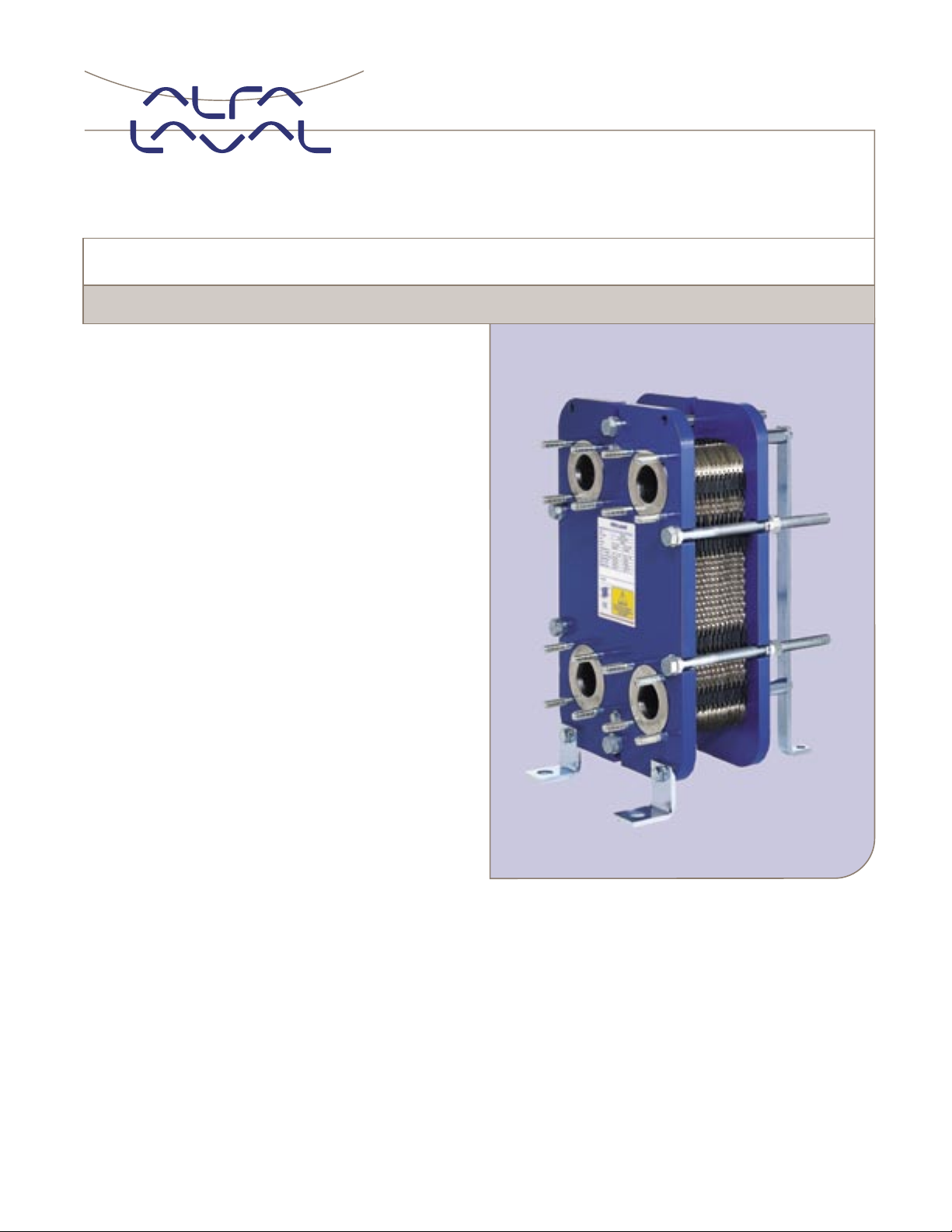
M3
Plate heat exchanger
Applications
General heating and cooling duties. Heating by means
of steam.
Standard design
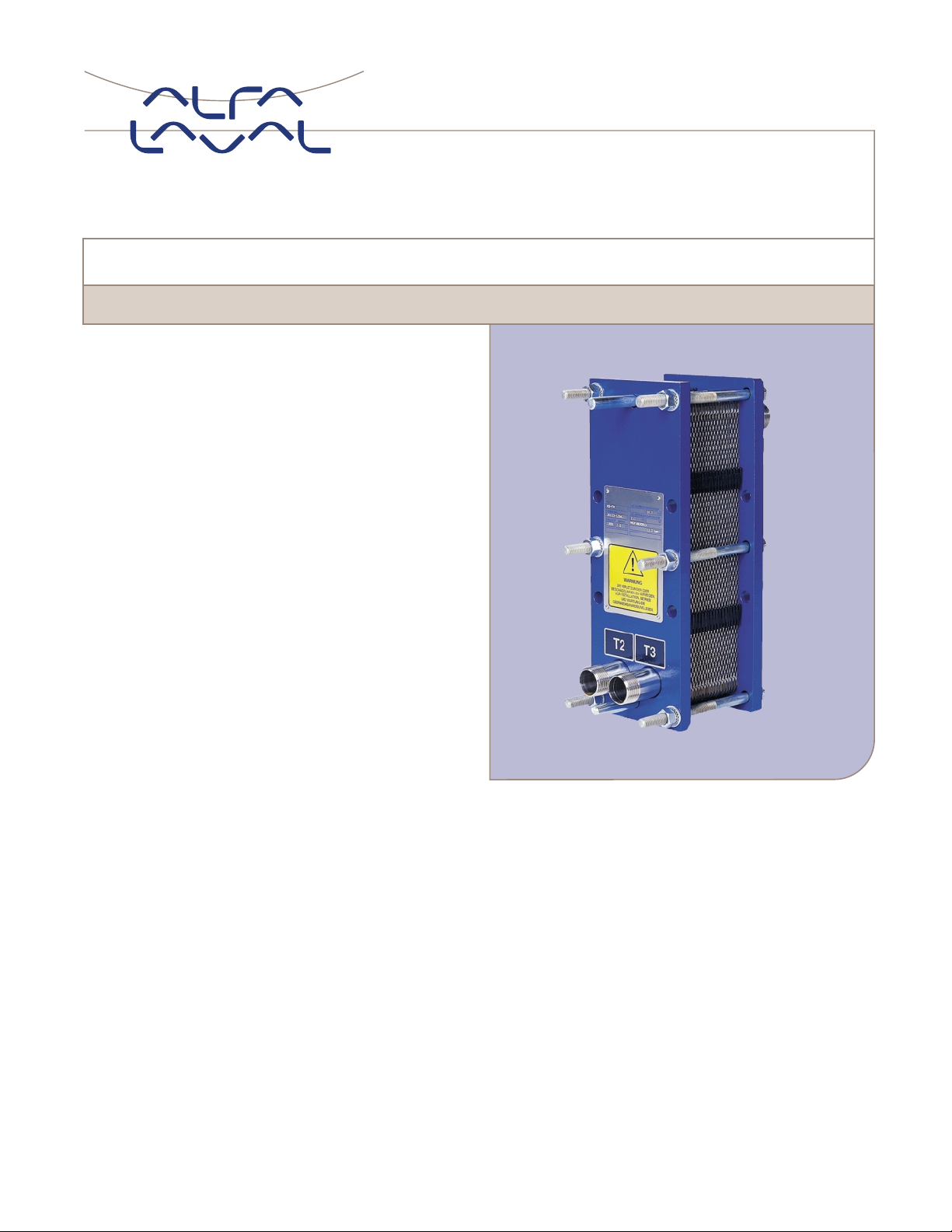
The plate heat exchanger consists of a pack of corrugated
metal plates with portholes for the passage of the two fluids
between which heat transfer will take place.
The plate pack is assembled between a fixed frame plate
and a movable pressure plate and compressed by tightening
bolts. The plates are fitted with a gasket which seals the
interplate channel and directs the fluids into alternate channels.
The number of plates is determined by the flow rate, physical
properties of the fluids, pressure drop and temperature
program. The plate corrugations promote fluid turbulence and
support the plates against differential pressure.
The plate and the pressure plate are suspended from an
upper carrying bar and located by a lower guiding bar, both
of which are fixed to a support column.
Connections are located in the frame plate or, if either or both
fluids make more than a single pass within the unit, in the
frame and pressure plates.
Typical capacities
Liquid flow rate
Up to 60 GPM, depending on media, permitted pressure drop
and temperature program.
Water heating by steam
50 to 250 kW, 14 tons to 90 tons
M3-VG
Plate types
M3 and M3-X, where M3 provides parallel and
M3-X diagonal flow (see figures on the next page).
M3D, double wall plates.
Frame types
VG
VGL (non-ASME)
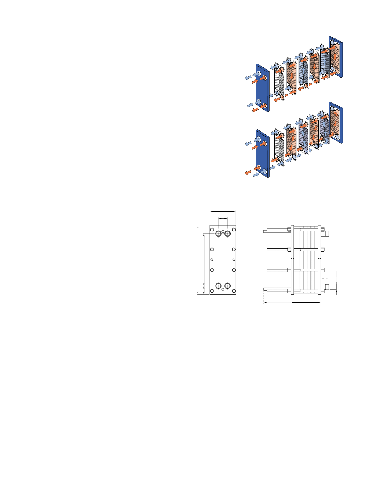
Working principle
Channels are formed between the plates and the corner ports
are arranged so that the two media flow through alternate
channels. The heat is transferred through the plate between
the channels, and complete counter-current flow is created
for highest possible efficiency. The corrugation of the
plates provides the passage between the plates, supports
each plate against the adjacent one and enhances
the turbulence, resulting in efficient heat transfer.
Standard materials
Frame plate
Mild steel, painted
Nozzles
Stainless steel AISI 316 or Titanium
Plates
Stainless steel AISI 316 or Titanium
Gaskets
M3 Nitrile, EPDM
M3X Nitrile, EPDM, Viton
®
M3D Nitrile, EPDM
Connections
1-1⁄4" NPT
Technical data
Mechanical design pressure (g)/temperature
VG 230 Psig/320ºF
FGL 230 Psig/320°F (non-ASME)
Maximum heat transfer surface
40 sq. ft
Particulars required for quotation
– Flow rates or heat load
– Temperature program
– Physical properties of liquids in question (if not water)
– Desired working pressure
– Maximum permitted pressure drop
– Available steam pressure
Dimensions
Measurements (mm)
The number of bolts may vary depending on pressure rating.
How to contact Alfa Laval
Contact details for all countries
are continually updated on our website.
Please visit www.alfalaval.com to
access the information directly.
ENSR00001USEN 0206 All rights reserved for changes in specifications
Flow principle of an M3
plate heat exchanger
Flow principle of an M3-X
plate heat exchanger
2-
1
⁄2"
7"
2-
3
⁄8"
19"
14"
7-1⁄2" – 19-1⁄2"
1-
1
⁄4"
THERMAL TRANSFER SYSTEMS, INC.
SALES@THERMALTRANSFERSYSTEMS.COM
PH: 800-527-0131 FAX: 972-242-7568
M6
Plate heat exchanger
Applications
General heating and cooling duties. Heating by means
of steam.
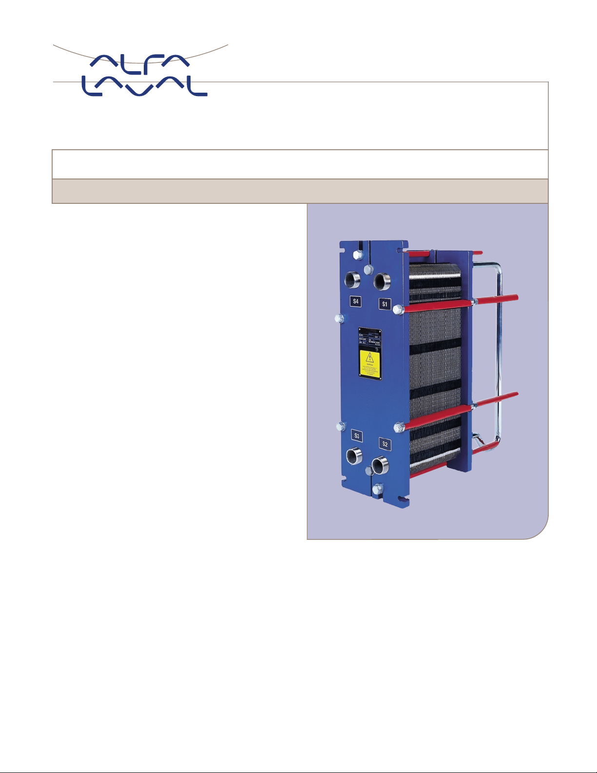
Standard design
The plate heat exchanger consists of a pack of corrugated
metal plates with portholes for the passage of the two fluids
between which heat transfer will take place.
The plate pack is assembled between a fixed frame plate
and a movable pressure plate and compressed by tightening
bolts. The plates are fitted with a gasket which seals the
interplate channel and directs the fluids into alternate
channels. The number of plates is determined by the flow
rate, physical properties of the fluids, pressure drop and
temperature program. The plate corrugations promote fluid
turbulence and support the plates against differential pressure.
The plate and the pressure plate are suspended from an
upper carrying bar and located by a lower guiding bar, both
of which are fixed to a support column.
Connections are located in the frame plate or, if either or both
fluids make more than a single pass within the unit, in the
frame and pressure plates.
Typical capacities
Liquid flow rate
Up to 250 gpm, depending on media, permitted pressure drop
and temperature program.
Water heating by steam
80 tons to 225 tons
Plate types
M6 and M6M
Frame types
FG, FD (ASME design)
FGL (non-ASME)
M6-FG
How to contact Alfa Laval
Contact details for all countries
are continually updated on our website.
Please visit www.alfalaval.com to
access the information directly.
ENSR00002USEN 0206 All rights reserved for changes in specifications
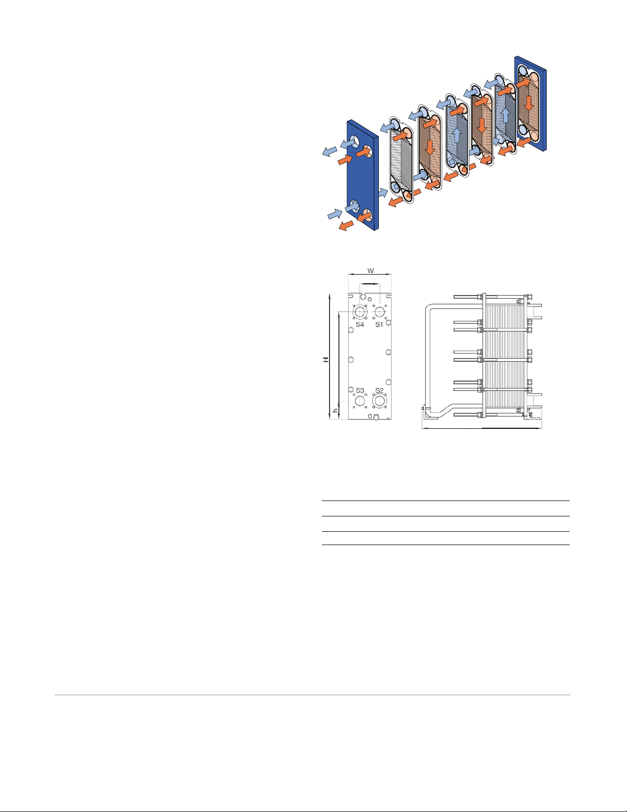
Working principle
Channels are formed between the plates and the corner ports
are arranged so that the two media flow through alternate
channels. The heat is transferred through the plate between
the channels, and complete counter-current flow is created
for highest possible efficiency. The corrugation of the
plates provides the passage between the plates, supports
each plate against the adjacent one and enhances
the turbulence, resulting in efficient heat transfer.
Standard materials
Frame plate
Mild steel, painted
Nozzles
Flange: Stainless steel, Titanium
Lined: Stainless steel, Titanium
Pipe: Stainless steel
Plates
Stainless steel AISI 316
Titanium (M6M only)
Gaskets
M6 Nitrile, EPDM, HeatSeal F™
M6M Nitrile, EPDM, HeatSeal F™, Viton
®
G
Connections
Pipe connections:
2" NPT
With flanges:
FG 2" SOLJ ANSI 150
FD 2" SOLJ ANSI 150/ANSI 300
Technical data
Mechanical design pressure (g)/temperature
FGL 150 psig/320ºF (non-ASME)
FG 150 psig/356ºF
FD 360 psig/356ºF
Maximum heat transfer surface
410 sq. ft.
Dimensions
Measurements (mm)
Type H W h
M6-FGL 36.22" 12.60" 5.51"
M6-FG 36.22" 12.60" 5.51"
M6-FD 37" 13" 5.91"
The number of tightening bolts may vary depending on pressure rating.
Particulars required for quotation
– Flow rates or heat load
– Temperature program
– Physical properties of liquids in question (if not water)
– Desired working pressure
– Maximum permitted pressure drop
– Available steam pressure
Flow principle of a plate heat exchanger
20" – 55"
5.51"
25.2"
THERMAL TRANSFER SYSTEMS, INC.
SALES@THERMALTRANSFERSYSTEMS.COM
PH: 800-527-0131 FAX: 972-242-7568
TS6
Plate Heat Exchanger
Applications
General heating and cooling duties. Heating by means
of steam.
Standard design
The plate heat exchanger consists of a pack of corrugated
metal plates with portholes for the passage of the two fluids
between which heat transfer will take place.
The plate pack is assembled between a fixed frame plate and
a movable pressure plate and compressed by tightening bolts.
The plates are fitted with a gasket which seals the interplate
channel and directs the fluids into alternate channels. The
number of plates is determined by the flow rate, physical
properties of the fluids, pressure drop and temperature
program. The plate corrugations promote fluid turbulence and
support the plates against differential pressure.
The plate and the pressure plate are suspended from an upper
carrying bar and located by a lower guiding bar, both of which
are fixed to a support column.
Connections are located in the frame plate or, if either or both
fluids make more than a single pass within the unit, in the
frame and pressure plates.
Typical capacities
Liquid flow rate
Up to 20 kg/s (158,400 lb/hr), depending on media, permitted
pressure drop and temperature program.
Water heating by steam
200 – 1,800 kW (682,400 – 6,141,600 BTU/hr)
Plate types
TS6M
Frame types
FG and FD
TS6-MFG
 Loading...