

Page 1

CA-2000
FLUID COOLING | Shell & Tube CA-2000 Series
COPPER & STEEL CONSTRUCTION
Features
n
Super High Flow
n
Largest Flow Rates &
Heat Transfer Available
n
ASME Code
n
Rugged Steel Construction
n
Custom Designs Available
n
Competitively Priced
n
3/ 8” & 5/8” Tubes Available
n
Max. 10” Diameter, 12’ Long
n
150 # ANSI/ASME Flanged Shell
Connections (Metric Available)
n
Optional Construction on CA-2000
Series: Tubes, Tubesheets, and End
WATER COOLED
Bonnets
n
End Bonnets Removable For Servicing
n
Saddle Brackets For Incremental
Mounting
n
ASME Code (Section VIII, Division I)
and TEMA-C Construction
Available (Consult Factory for Ordering
Information)
CA -2 000
Ratings
Maximum Shell Pressure 150 psi
Maximum Tube Side Pressure 150 psi
Maximum Temperature 300° F
How to Order
–
Model
Series
CA
CAM
CA = NPT tubeside bottom connections; A SME/ANSI flange shell top connec tions.
CAM = BSPP shellside connections ; BSPP tubeside connections.
Model Size Selected
– –
Baff le
Spacing
Materials
Headers Steel
Shell Steel
Shell Connections Steel
B a f f l e s B r a s s
End Bonnets Cast Iron
Mounting Brackets Steel/Cast Iron
Gaskets Nitrile Rubber/Cellulose Fiber
Nameplate Aluminum Foil
–
Tube
Diameter
Code
6 - 3/8”
10 - 5/8”
Tubeside
Passes
0 - One Pass
T - Two Pass
F - Four Pass
–
Cooling
Tub e
Material
Blank - Copper
CN - CuNi
SS - Stainless
Steel
AD - Admiralty
Brass
Maximum Flow Rates
Shell Side ( GPM) Tube Side GPM
6” 9” One Two Four
Baff le Baff le Pass Pass Pass
210 320 652 326 163
–
End
Bonnet
Material
Blank - Cast Iron
NP - Electr oless
Nickel Plate
Tubesheet
Material
Blank - Cast Iron
W - CuNi
S - Stainless
Steel
––
Zinc
Anodes
Blank - None
Z - Zinc
TTPSales@thermasys.com 262.554.8330 www.thermaltransfer.com
98
Page 2

Dimensions
4“ 150# RF ASME/ANSI FLANGE
W/8 HOLES, .75 DIA.
ON 7.50 OBC
2 PLACES
1/2 NPT DRAIN
OPTIONAL ZINC
ANODE LOCATION
2 PLACES
1/2 NPT DRAIN
4 PLACES
.75 DIA. HOLE
2 EACH END
1/2 NPT DRAIN
OPTIONAL ZINC
ANODE LOCATION
2 PLACES
5“ 150# RF ASME/ANSI
FLAT FACE FLANGE
W/8 HOLES, .88 DIA.
ON 8.50 OBC
BOTH ENDS
J
E
G
12.50
OC
D
NB
A
F
H
4“ 150# RF ASME/ANSI FLANGE
W/8 HOLES, .75 DIA.
ON 7.50 OBC
2 PLACES
1/2 NPT DRAIN
OPTIONAL ZINC ANODE LOCATION
2 PLACES
1/2” NPT DRAIN
4 PLACES
.75 DIA. HOLE
2 EACH END
1/2” NPT DRAIN
2 PLACES
G
12.50
5.00
3“ NPT
2 PLACES
22° 30’
J
E
F
O
D
C
H
A
B
N
4“ 150# RF ASME/ANSI FLANGE
W/8 HOLES, .75 DIA.
ON 7.50 OBC
2 PLACES
1/2 NPT DRAIN
OPTIONAL ZINC
ANODE LOCATION
2 PLACES
1/2” NPT DRAIN
4 PLACES
.75 DIA. HOLE
2 EACH END
G
1.75
2-1/2“ NPT
2 PLACES
J
E
F
O
D
C
H
A
B
N
1/2 NPT DRAIN
OPTIONAL ZINC
ANODE LOCATION
3 PLACES
4.00
12.50
One Pass
Two Pass
Model A N O
CA-2036 49.64
CA-2048 61.64
CA-2060 73.64
CA-2072 85.64
CA-2084 97.64 11.82 15.92
CA-2096 109.64
CA-20108 121.64
CA-20120 133.64
CA-20132 145.64
CA-20144 157.64
Model A N O
CA-2036 45.55
CA-2048 57.55
CA-2060 69.55
CA-2072 81.55
CA-2084 93.55 9.90 14.38
CA-2096 105.55
CA-20108 117.55
CA-20120 129.55
CA-20132 141.55
CA-20144 153.55
CA-2000
WATER COOLED
Four Pass
Model B C D E F G H J
CA-2036 26 18
CA-2048 38 30
CA-2060 50 42 6.19 DIA
CA-2072 62 54 Raised
CA-2084 74 66 10.5 DIA 9 8 10 14.88 DIA Face
CA-2096 86 78 2 Places
CA-20108 98 90
CA-20120 110 102
CA-20132 122 114
CA-20144 134 126
Model A N O
CA-2036 45.34
CA-2048 57.34
CA-2060 69.34
CA-2072 81.34
CA-2084 93.34 9.78 13.78
CA-2096 105.34
CA-20108 117.34
CA-20120 129.34
CA-20132 141.34
CA-20144 153.34
NOTE: We reserve the right to make
reasonable design changes without
notice. Dimensions are in inches.
www.thermaltransfer.com TTPSales@thermasys.com 262.554.8330
CA -2 000
99
Page 3
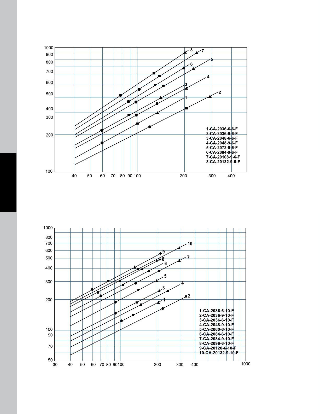
CA-2000
HORSEPOWER REMOVED @ 40°F APPROACH
OIL FLOW (GPM @ 2:1 O/W RATIO)
OIL PRESSURE
DROP
= 5 PSI
= 10 PSI
= 20 PSI
HORSEPOWER REMOVED @ 40°F APPROACH
OIL FLOW (GPM @ 2:1 O/W RATIO)
Performance Curves
3/8” Tubes
WATER COOLED
5/8” Tubes
CA -2 000
100
TTPSales@thermasys.com 262.554.8330 www.thermaltransfer.com
Page 4
Selection Procedure
5
4
3
2.5
2
1.5
1
.8
.7
.6
.5
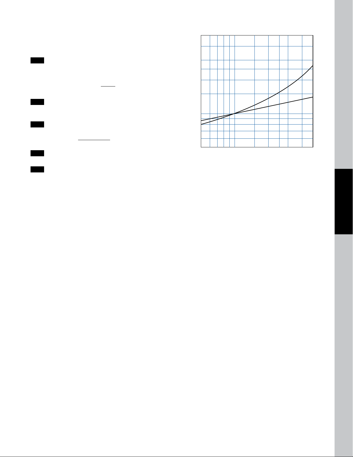
50 60 70 80 100 150 200 250 300 400 500
A
B
OIL VISCOSITY - SSU
VISCOSITY CORRECTION
Performance Curves are based on 100SSU oil leaving the cooler 40°F
higher than the incoming water temperature (40°F approach temperature).
Curves are based on a 2:1 oil to water ratio.
Step 1 Determine the Heat Load. This will vary with different systems,
but typically coolers are sized to remove 25 to 50% of the input
nameplate horsepower. (Example: 100 HP Power Unit x .33 = 33
HP Heat load.)
If BTU/Hr. is known: HP =
2545
BTU/Hr
Step 2 Determine Approach Temperature.
Desired oil leaving cooler °F – Water Inlet temp. °F =
Step 3 Determine Curve Horsepower Heat Load. Enter the
information from above:
HP heat load x
Actual Approach Correction A Horsepower
Step 4 Enter curves at oil flow through cooler and curve horsepower.
Any curve above the intersecting point will work.
Step 5 Determine Oil Pressure Drop from Curves. Multiply pressure
drop from curve by correction factor B found on oil viscosity
correction curve.
l = 5 PSI; n = 10 PSI; s = 20 PSI; : = 40 PSI.
40
Viscosity = Curve
x
Actual
Approach
Oil Temperature
Oil coolers can be selected by using entering or leaving oil tempertures.
Typical operating temperature ranges are:
Hydraulic Motor Oil 110°F - 130°F
Hydrostatic Drive Oil 130°F - 180°F
Lube Oil Circuits 110°F - 130°F
Automatic Transmission Fluid 200°F - 300°F
Desired Reservoir Temperature
Return Line Cooling : Desired temperature is the oil temperature
leaving the cooler. This will be the same temperature that will be found
in the reservoir.
CA-2000
WATER COOLED
Off-Line Recirculation Cooling Loop : Desired temperature is the
temperature entering the cooler. In this case, the oil temperature change
must be determined so that the actual oil leaving temperature can be found.
Calculate the oil temperature change (Oil
T= (BTU’s/Hr.)/GPM Oil Flow x 210).
Oil
#
To calculate the oil leaving temperature from the cooler, use this formula:
Oil Leaving Temperature = Oil Entering Temperature - Oil
This formula may also be used in any application where the only temperature
available is the entering oil temperature.
Oil Pressure Drop: Most systems can tolerate a pressure drop through the
heat exchanger of 20 to 30 PSI. Excessive pressure drop should be avoided.
Care should be taken to limit pressure drop to 5 PSI or less for case drain
applications where high back pressure may damage the pump shaft seals.
#
T) with this formula:
#
T.
CA -2 000
www.thermaltransfer.com TTPSales@thermasys.com 262.554.8330
101
 Loading...