

Page 1

FLUID COOLING | Shell & Tube EK Series
COPPER & STEEL CONSTRUCTION
Features
n
Compact Size
n
High Efficiency Finned Bundle Design
n
Low Cost
n
Optional Patented Built-in
Surge-Cushion® Relief Bypass
n
3/16” Tube Size
n
Heat Removal up to 400 Horsepower
(300 kW)
n
Oil Flow rates up to 80 U.S. GPM (300
Liters/min.)
n
Large Oil Connections for Minimum
Entering and Exiting Flow Restriction
n
Removable End Bonnets for easy
WATER COOLED EK
tube cleaning
n
Mounting Brackets Designed so
that Cooler can be Rotated in 90°
Increments
n
High Pressure Ratings
n
Complete Line of Accessories Available
Ratings
Operating Pressure/Shell side 500 psi
Operating Pressure/Tubeshell side 150 psi
Operating Temperature 250° F
Materials
Shell Steel
Tube Sheets Steel
B a f f l e s Steel
Mounting Brackets Steel
Gaskets Nitrile Rubber/Cellulose Fiber
Nameplate Aluminum Foil
Tub es Copper
Fins Aluminum
End Caps Grey Iron
Surge-Cushion (Option)
The SURGE-CUSHION® is a protective device
(patented) designed to internally bypass
a portion of the oil flow during cold start
conditions, or when sudden flow surges
temporarily exceed the maximum flow allowed
for a given cooler. This device may replace an
external bypass valve, but it is not intended to
bypass the total oil flow.
Maximum Flow Rates
Unit Side One Two Four
Size GPM Pass Pass Pass
500 20 13 6 N/A
Cutaway view shows
high performance copper
tube/aluminum fin cooling
chamber with patented SURGECUSHION
Tube Side GPM
Shell
®
relief bypass valve.
How to Order
– – –
Model
Series
EK
EKS
EKM
EK
EKF
EKFM
EK = NPT Oil connections; NPT Water connec tions.
EKS = SAE O-Ring Oil connec tions; NPT Water connec tions.
EKM = BSPP Oil connections; BSPP Water connections.
EKF = SAE 4 Bolt Flange (Tappe d SAE) Oil connections; NPT Water connections.
EKFM = SAE 4 Bolt Flange (Tapped Metric) Oil conne ctions; BSPP Water connections.
TTPSales@thermasys.com 262.554.8330 www.thermaltransfer.com
72
Model Size
Selected
B a f f l e
Spacing
EK-1036
& EK-1048
Models Only
Tub esid e
Passes
0 - One Pass
T - Two Pass
F - Four Pass
–
Surge
Cushion
Blank - No Relief
Bypass
R - Relief Bypass
700 60 24 12 6
1000 80 56 28 14
Incorrect installation can cause premature failure.
–
Cooling Tube
Material
Blank - Copper
CN - CuNi
–
End Bonnet
Material
Blank - Cast Iron
NP - Electr oless
Nickel Plate
Page 2

Dimensions
M
D
N
E
A
H
J
B
L
K
C
F
G
X
Y
Z (4 PLACES)
FLANGE
SIZE
1-1/2 2
X
Y
EKF Z
EKFM Z
1.41
2.75
1/2 - 13 UNC-2B
M-12
1.69
3.06
NOTE: We reserve the right to make reasonable design changes without notice. All dimensions are in inches.
MODEL
A B
SAE
FLANGE
SAE
O-RING
SAE
FLANGE
BSPP
C
D E F G H J K
L
NPT
M
NPT
BSPP
N
EK-505
EK-508
EK-510
EK-512
EK-514
EK-518
EK-524
EK-536
EK-708
EK-712
EK-714
EK-718
EK-724
EK-736
EK-1012
EK-1014
EK-1018
EK-1024
EK-1036
EK-1048
7.38
10.38
12.38
14.38
16.38
20.38
26.38
38.38
11.12
15.12
17.12
21.12
27.12
39.12
15.33
17.33
21.33
27.33
39.33
51.33
2.19
3.85
5.85
7.85
9.85
13.85
19.85
31.85
3.00
7.00
9.00
13.00
19.00
31.00
6.18
8.18
12.18
18.18
30.18
42.18
7.44
10.44
12.44
14.44
16.44
20.44
26.44
38.44
10.71
14.71
16.71
20.71
26.71
38.71
15.45
17.45
21.45
27.45
39.45
51.45
3.5
MAX.
WIDTH
5.0
MAX.
WIDTH
6.5
MAX.
WIDTH
2.55
DIA.
3.52
DIA.
5.05
DIA.
3.74
3.90
5.47
7.64
N/A
5.71
8.28
1.62
2.59
4.00
2.59
3.26
4.07
4.57
2.50
3.00
4.00
.34
x
.62
SLOT
.44
x
.75
SLOT
.44
x
1.00
SLOT
N/A
1/4
1/2
3/4
11/2
2
1/2
3/4
11/2
#8 3/4-16
UNF-2B
#12
1
1
/16-12
UN-2B
#24
1
7
/8-12
UN-2B
N/A
11/2
2
3/4
1
1
/4
11/2
NPT
BSPP
NPT / BSPP
SAE O-RING
One Pass
Flange
Size 1-1/2 2
X 1.41 1. 69
Y 2.75 3.06
EKF Z 1/2 - 13 UNC-28
EKFM Z M-12
www.thermaltransfer.com TTPSales@thermasys.com 262.554.8330
WATER COOLED EK
73
EK
Page 3

Dimensions
D
C
G
E
F
M
A
H
L
K
P
N
J
B
X
Y
Z (4 PLACES)
A B
SAE
FLANGE
SAE
O-RING
SAE
FLANGE
BSPP
C
D E F G H J K P
L
NPT
M
NPT
BSPP
N
NPT
BSPP
NPT / BSPP
SAE O-RING
MODEL
EK-505
EK-508
EK-510
EK-512
EK-514
EK-518
EK-524
EK-536
EK-708
EK-712
EK-714
EK-718
EK-724
EK-736
EK-1012
EK-1014
EK-1018
EK-1024
EK-1036
EK-1048
7.38
10.38
12.38
14.38
16.38
20.38
26.38
38.38
10.19
14.19
16.19
20.19
26.19
39.19
14.58
16.58
20.58
26.58
38.58
50.58
2.19
3.85
5.85
7.85
9.85
13.85
19.85
31.85
3.00
7.00
9.00
13.00
19.00
31.00
6.18
8.18
12.18
18.18
30.18
42.18
7.44
10.44
12.44
14.44
16.44
20.44
26.44
38.44
10.71
14.71
16.71
20.71
26.71
38.71
15.45
17.45
21.45
27.45
39.45
51.45
3.5
MAX.
WIDTH
5.0
MAX.
WIDTH
6.5
MAX.
WIDTH
2.55
DIA.
3.52
DIA.
5.05
DIA.
3.74
3.90
5.47
7.64
N/A
5.71
8.28
1.62
2.59
4.00
2.59
3.26
3.57
4.45
2.50
3.00
4.00
1.12
1.62
2.38
.34
x
.62
SLOT
.44
x
.75
SLOT
.44
x
1.00
SLOT
N/A
1/4
1/2
3/4
1
1
/2
2
1/2
3/4
1
1
/2
#8 3/4-16
UNF-2B
#12
1
1
/16-12
UN-2B
#24
1
7
/8-12
UN-2B
N/A
1
1
/2
2
3/8
3/4
1.0
Two Pass
WATER COOLED EK
Flange
Size 1-1/2 2
X 1.41 1. 69
Y 2.75 3.06
EKF Z 1/2 - 13 UNC-28
EKFM Z M-12
NOTE: We reserve the right to make reasonable design changes without notice. All dimensions are in inches.
EK
74
TTPSales@thermasys.com 262.554.8330 www.thermaltransfer.com
Page 4
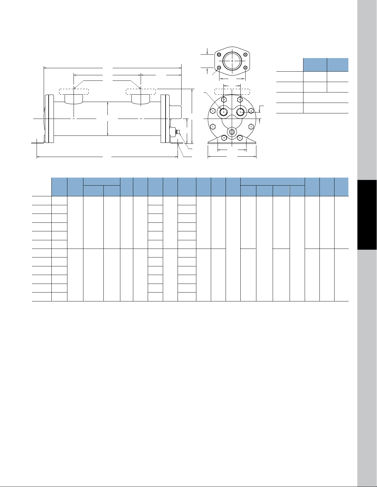
Dimensions
P
J
B
R
N
L
D
C
GF
A
M
E
H
K
X
Y
Z (4 PLACES)
MODEL
A B
NPT / BSPP
SAE O-RING
SAE
FLANGE
SAE
O-RING
SAE
FLANGE
BSPP
C
D E F G H J K P
L
NPT
R
M
NPT
BSPP
N
EK-708
EK-712
EK-714
EK-718
EK-724
EK-736
EK-1012
EK-1014
EK-1018
EK-1024
EK-1036
EK-1048
10.37
14.37
16.37
20.37
26.37
38.37
14.33
16.33
20.33
26.33
38.33
50.33
3.00
7.00
9.00
13.00
19.00
31.00
6.18
8.18
12.18
18.18
30.18
42.18
10.71
14.71
16.71
20.71
26.71
38.71
15.45
17.45
21.45
27.45
39.45
51.45
5.0
MAX.
WIDTH
6.5
MAX.
WIDTH
3.52
DIA.
5.05
DIA.
5.47
7.64
5.71
8.28
2.59
4.00
4.25
4.45
3.00
4.00
.44
x
.75
SLOT
.44
x
1.00
SLOT
1/4
1
1
/2
2
#24
1
7
/8-12
UN-2B
1
1
/2
2
1
1
/2
1/2
3/4
1.75
2.50
.70
.89
NPT
BSPP
Four Pass
Flange
Size 1-1/2 2
X 1.41 1. 69
Y 2.75 3.06
EKF Z 1/2 - 13 UNC-28
EKFM Z M-12
NOTE: We reserve the right to make reasonable design changes without notice. All dimensions are in inches.
www.thermaltransfer.com TTPSales@thermasys.com 262.554.8330
WATER COOLED EK
75
EK
Page 5
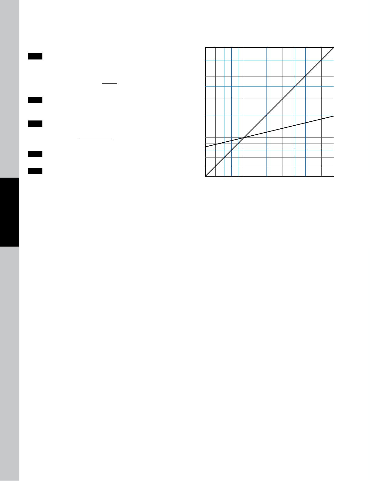
50 60 70 80 90100 150 200 250 300 400 500
.5
.6
.7
.8
.9
1
2
3
4
5
1.5
2.5
OIL VISCOSITY CORRECTION MULTIPLIERS
OIL VISCOSITY - SSU
VISCOSITY CORRECTION
A
B
Selection Procedure
Performance Curves are based on 100SSU oil leaving the cooler 40°F
higher than the incoming water temperature (40°F approach temperature).
Step 1 Determine the Heat Load. This will vary with different systems,
but typically coolers are sized to remove 25 to 50% of the input
nameplate horsepower. (Example: 100 HP Power Unit x .33 = 33
HP Heat load.)
If BTU/Hr. is known: HP =
2545
BTU/Hr
Step 2 Determine Approach Temperature.
Desired oil leaving cooler °F – Water Inlet temp. °F =
Step 3 Determine Curve Horsepower Heat Load. Enter the
information from above:
HP heat load x
Actual Approach Correction A Horsepower
Step 4 Enter curves at oil flow through cooler and curve horsepower.
Any curve above the intersecting point will work.
Step 5 Determine Oil Pressure Drop from Curves. Multiply pressure
drop from curve by correction factor B found on oil viscosity
WATER COOLED EK
correction curve.
l = 5 PSI; n = 10 PSI; s = 20 PSI.
40
Viscosity = Curve
x
Oil Temperature
Oil coolers can be selected by using entering or leaving oil tempertures.
Typical operating temperature ranges are:
Hydraulic Motor Oil 110°F - 130°F
Hydrostatic Drive Oil 130°F - 180°F
Lube Oil Circuits 110°F - 130°F
Automatic Transmission Fluid 200°F - 300°F
Desired Reservoir Temperature
Return Line Cooling: Desired temperature is the oil temperature
leaving the cooler. This will be the same temperature that will be found
in the reservoir.
Actual
Approach
Off-Line Recirculation Cooling Loop : Desired temperature is the
temperature entering the cooler. In this case, the oil temperature change
must be determined so that the actual oil leaving temperature can be found.
Calculate the oil temperature change (Oil
T= (BTU’s/Hr.)/GPM Oil Flow x 210).
Oil
76
#
To calculate the oil leaving temperature from the cooler, use this formula:
Oil Leaving Temperature = Oil Entering Temperature - Oil
This formula may also be used in any application where the only temperature
available is the entering oil temperature.
Oil Pressure Drop: Most systems can tolerate a pressure drop through the
heat exchanger of 20 to 30 PSI. Excessive pressure drop should be avoided.
Care should be taken to limit pressure drop to 5 PSI or less for case drain
applications where high back pressure may damage the pump shaft seals.
EK
TTPSales@thermasys.com 262.554.8330 www.thermaltransfer.com
T) with this formula:
#
T.
#
Page 6
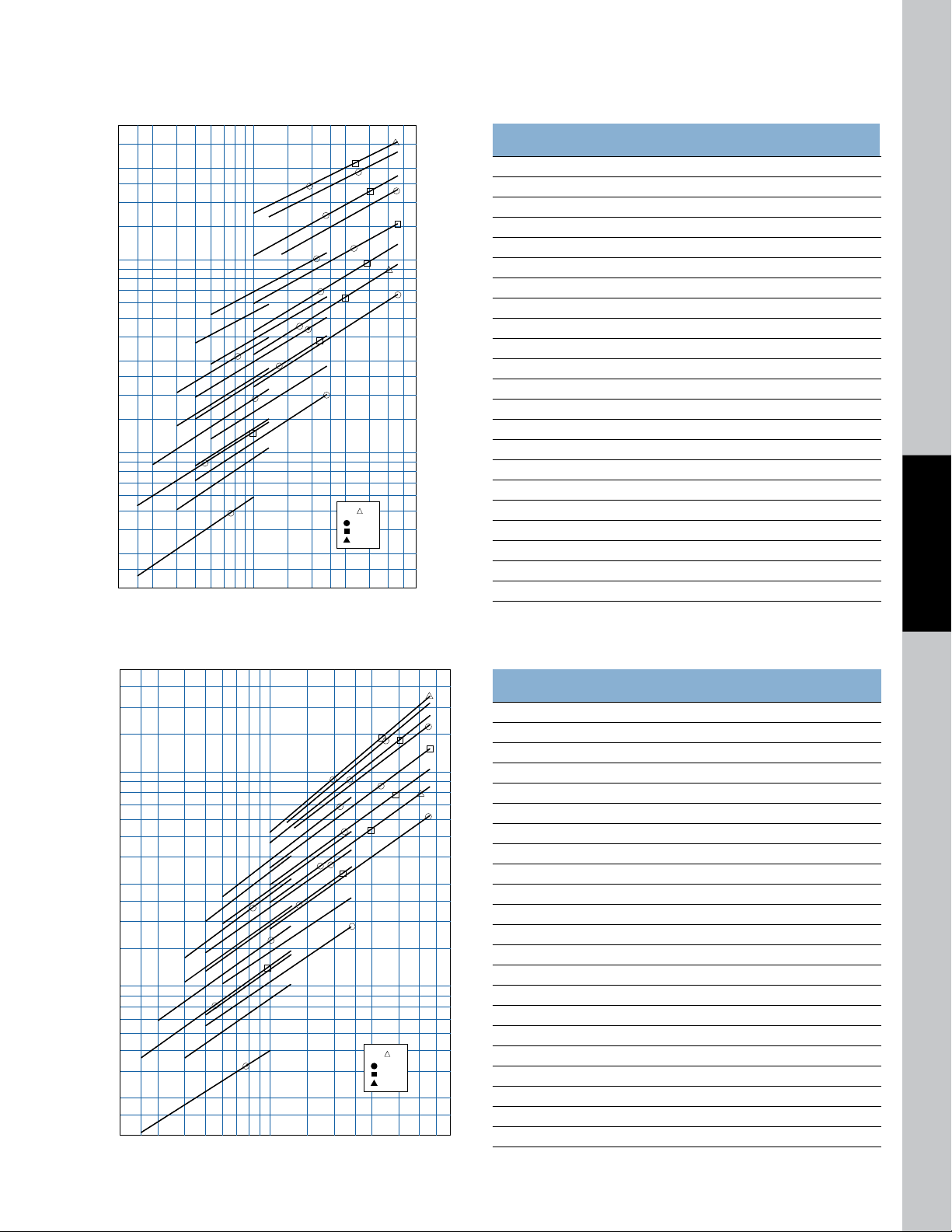
Performance Curves
8
9
10
15
20
25
30
40
50
60
70
80
90
100
150
200
250
300
400
500
7
6
5
3
2
4
2.5
2 9 10 15 20 25 30 40 50 608765432.5
HORSEPOWER REMOVED IN COOLER
●
●
●
●
●
●
●
●
●
●
●
●
●
●
●
●
■
■
■
■
■
■
■
▲
▲
1
2
3
5
4
6
9
12
10
13
15
16
17
18
19
20
21
22
14
11
7
8
OIL P
= 5 PSI
= 10 PSI
= 20 PSI
9 10 15 20 25 30 40 50 60
8
9
10
15
20
25
30
40
50
22
21
20
19
18
17
14
13
12
10
9
7
8
6
5
3
1
2
4
11
16
15
60
70
80
90
100
150
200
250
7
6
5
3
2
4
2.5
8765432 2.5
OIL FLOW (GPM)
HORSEPOWER REMOVED IN COOLER
●
●
●
●
●
●
●
●
●
●
●
●
●
●
●
●
■
■
■
■
■
■
■
▲
▲
OIL P
= 5 PSI
= 10 PSI
= 20 PSI
1:1 Oil to Water Ratio – High Water Usage
Weights (lbs)
Models Net Approx. Shipping
1. EK-505-0 6 7
2. EK-508-0 7 8
3. EK-510-0 8 9
4. EK-512-0 9 10
5. EK-514-0 10 11
6. EK-518-0 11 12
7. EK-524-0 13 14
8. EK-536-0 17 18
9. EK-708-0 15 16
10. EK-712-0 18 19
11. EK-714-0 19 20
12. EK-718-0 22 23
13. EK-724-0 26 28
14. EK-736-0 34 36
15. EK-1012-0 35 37
16. EK-1014-0 38 40
17. EK-1018-0 42 45
18. EK-1024-0 50 55
19. EK-1036-9-0 67 85
20. EK-1036-6-0 67 85
21. EK-1048-8-0 78 95
22. EK-1048-6-0 78 95
WATER COOLED EK
2:1 Oil to Water Ratio – Medium Water Usage
Weights (lbs)
Models Net Approx. Shipping
1. EK-505-T 6 7
2. EK-508-T 7 8
3. EK-510-T 8 9
4. EK-512-T 9 10
5. EK-514-T 10 11
6. EK-518-T 11 12
7. EK-524-T 13 14
8. EK-536-T 17 18
9. EK-708-T 15 16
10. EK-712-T 18 19
11. EK-714-T 19 20
12. EK-718-T 22 23
13. EK-724-T 26 28
14. EK-736-T 34 36
15. EK-1012-T 35 37
16. EK-1014-T 38 40
17. EK-1018-T 42 45
18. EK-1024-T 50 55
19. EK-1036-9-T 67 85
20. EK-1036-6-T 67 85
21. EK-1048-8-T 78 95
22. EK-1048-6-T 78 95
www.thermaltransfer.com TTPSales@thermasys.com 262.554.8330
77
Page 7
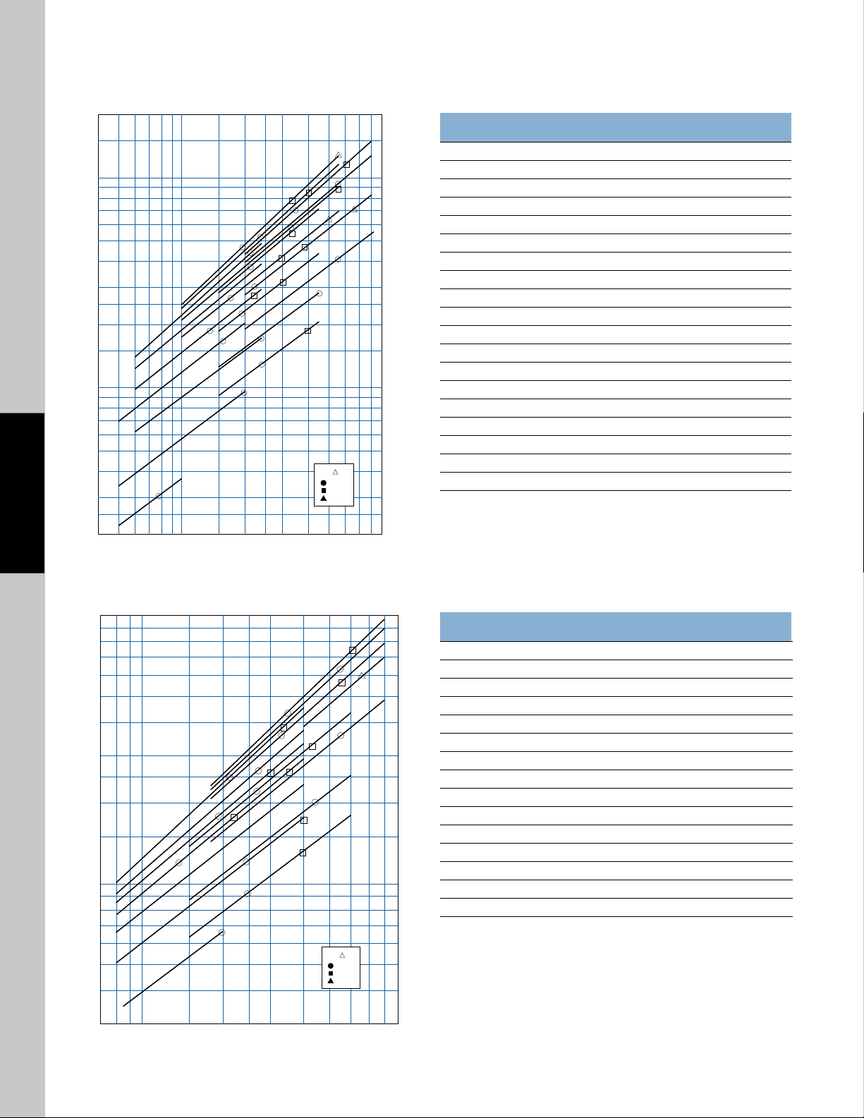
Performance Curves
9 10 15 20 25 30 40 50 60 70
8
9
10
15
20
25
30
40
50
60
70
80
90
100
150
7
6
5
3
2
4
2.5
87654 80
OIL FLOW (GPM)
HORSEPOWER REMOVED IN COOLER
●
●
●
●
●
●
●
●
●
●
●
●
●
●
●
●
●
●
■
■
■
■
■
■
■
■
■
■
▲
▲
▲
1
2
3
4
5
6
7
8
9
10
11
12
13
14
16
17
19
18
15
OIL P
= 5 PSI
= 10 PSI
= 20 PSI
9 10 15 20 25 30 40 50 60 70
8
9
10
15
20
25
30
40
50
60
70
80
90
100
7
6
5
1
2
3
4
5
6
7
15
14
13
12
11
9
8
10
3
4
87 80
OIL FLOW (GPM)
HORSEPOWER REMOVED IN COOLER
●
●
●
●
●
●
●
●
●
■
●
●
▲
●
■
■
■
■
■
■
■
■
●
OIL P
= 5 PSI
= 10 PSI
= 20 PSI
4:1 Oil to Water Ratio – Low Water Usage
WATER COOLED EK
Weights (lbs)
Models Net Approx. Shipping
1. EK-505-T 6 7
2. EK-508-T 7 8
3. EK-518-T 11 12
4. EK-708-F 15 16
5. EK-714-F 19 20
6. EK-724-F 26 28
7. EK-736-F 34 36
8. EK-708-T 15 16
9. EK-712-T 18 19
10. EK-718-T 22 23
11. EK-736-T 34 36
12. EK-1012-T 35 37
13. EK-1014-T 38 40
14. EK-1018-T 42 45
15. EK-1024-T 50 55
16. EK-1036-9-T 67 85
17. EK-1036-6-T 67 85
18. EK-1048-8-T 78 95
19. EK-1048-6-T 78 95
7:1 Oil to Water Ratio – Lower Water Usage
EK
TTPSales@thermasys.com 262.554.8330 www.thermaltransfer.com
78
Weights (lbs)
Models Net Approx. Shipping
1. EK-508-T 7 8
2. EK-708-F 15 16
3. EK-712-F 18 19
4. EK-714-F 19 20
5. EK-718-F 22 23
6. EK-124-F 26 28
7. EK-736-F 34 36
8. EK-708-T 15 16
9. EK-712-T 18 19
10. EK-724-T 26 28
11. EK-1012-T 35 37
12. EK-1018-T 42 45
13. EK-1024-T 50 55
14. EK-1036-9-T 67 85
15. EK-1048-8-T 78 95
EK
Page 8
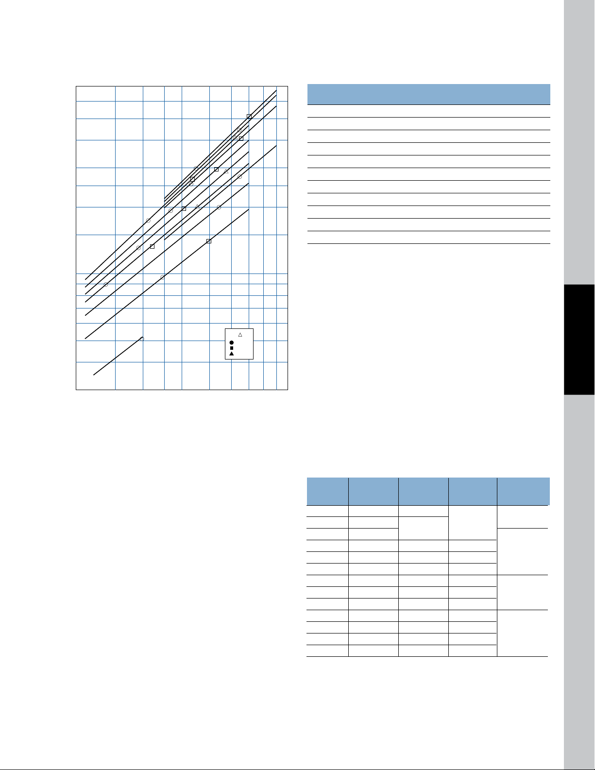
Performance Curves
10 15 20 25 30 40 50 60 70
8
9
10
15
20
25
30
40
50
60
70
7
6
5
3
4
80
●
●
●
●
●
●
●
●
●
●
●
■
■
▲
■
■
■
■
■
▲
▲
1
2
3
4
5
6
7
11
10
9
8
OIL FLOW (GPM)
HORSEPOWER REMOVED IN COOLER
OIL P
= 5 PSI
= 10 PSI
= 20 PSI
10:1 Oil to Water Ratio – Lowest Water Usage
Weights (lbs)
Models Net Approx. Shipping
1. EK-508-T 7 8
2. EK-708-F 15 16
3. EK-712-F 18 19
4. EK-714-F 19 20
5. EK-718-F 22 23
6. EK-724-F 26 28
7. EK-736-F 34 36
8. EK-1012-F 35 37
9. EK-1014-F 50 55
10. EK-1036-9-F 67 85
11. EK-1048-8-F 78 95
Recirculation Loop
Water Cooled Hydraulic Oil Coolers
BASIS:
n
40°F Entering temperature difference (Maintain reservoir 40°F
above the incoming water temperature)
n
Heat removal 30% of input horsepower
n
Hydraulic system flow (GPM) x 3 = Gallons; reservoir size
n
1 GPM cooler flow per HP heat to be removed
n
Turn-over reservoir 3-4 times per hour
n
Maximum flows
WATER COOLED EK
Minimum Minimum
System Required GPM Required GPM Heat E xchanger
Horsepower HP Heat Load Oil Flow Water Flow Model Number
3 .9 1
5 1.5
7.5 2.25
1
2
10 3 3 1.5
15 4.5 4.5 2
EK-5 05-T
EK-512-T
20 6 6 3
25 7.5 7.5 4
30 9 9 4.5 EK-712-T
40 12 12 6
50 15 15 7.5
60 18 18 9
75 22.5 23 12
EK -1012-T
100 30 30 15
www.thermaltransfer.com TTPSales@thermasys.com 262.554.8330
79
EK
 Loading...