

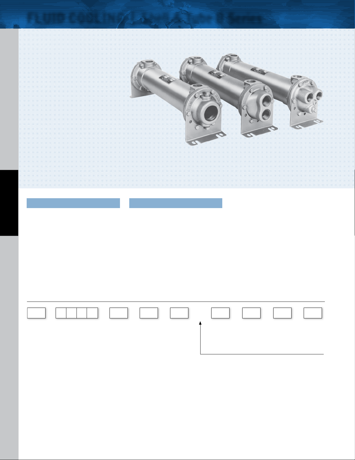
FLUID COOLING | Shell & Tube B Series
COPPER & STEEL CONSTRUCTION
Features
n
Young Touchstone Interchange
n
Optional Non-Ferrous Construction
n
Competitively Priced
n
1/4” or 3/8” Tubes Standard
n
Water to Water Applications
n
Sea Water Applications
n
Optional 90/10 Copper Nickel Cooling
Tubes and Bronze End Bonnets for Sea
Water Service
n
NPT, SAE O-Ring, SAE Flange, or BSPP
Shell Side Connections Available
n
End Bonnets Removable for Servicing
n
Mounting Feet Included (May be
WATER COOLED B
Rotated in 90° Increments)
Ratings
Maximum Shell Pressure 250 psi
Maximum Tube Side Pressure 150 psi
Maximum Temperature 350° F
Materials
Tub es Copper
Hubs & Tubesheets Steel or Brass
Shell Steel or Brass
B a f f l e s B r a s s
End Bonnets Cast Iron
Mounting Brackets S t e e l
Gaskets Nitrile Rubber/Cellulose Fiber
Nameplate Aluminum Foil
How to Order
–
Model
Series
SB
SBF
B
BS
BM
BF
BFM
Steel Hub
SB = NPT Shell Side, NP T Tube Side
SBF = SAE Flange (with UNC thre ads) Shell Side connec tions; NPT Tube Side connections
Brass Hub
B = NPT Shell Side connections ; NPT Tube Side connections
BS = SAE O-Ring Shell Side connections; NPT Tube Side connections
BM = BSPP Shell Side connections ; BSPP Tube Side connections
BF = SAE Flange (with UNC threads) Shell Side c onnections; NPT Tube Side connections
BFM = SAE Flange (with Metric threads) Shell Side connections; BSPP Tube Side connections
B
SAE flanges available on some models. C onsult fac tory for de tails.
Model Size Selected
– –
Baff le
Spacing
A - 1.125
B - 2.25
C - 4.5
D - 9.0
Diameter
4 - 1/4”
6 - 3/8”
Tube
Code
–
Tubeside
Passes
0 - One Pass
T - Two Pass
F - Four Pass
+
Shell
Material
Blank - Steel
BR - Brass
ADD FOR B SER IES MODEL S ONLY:
BR-C N-B-Z is to be used for all seaw ater/dirt y water applic ations.
–
Cooling
Tub e
Material
Blank - Copper
CN - CuNi
End
Bonnet
Material
Blank - Cast Iron
B - Bronze
––
Zinc
Anodes
Blank - None
Z - Zinc
102
TTPSales@thermasys.com 262.554.8330 www.thermaltransfer.com
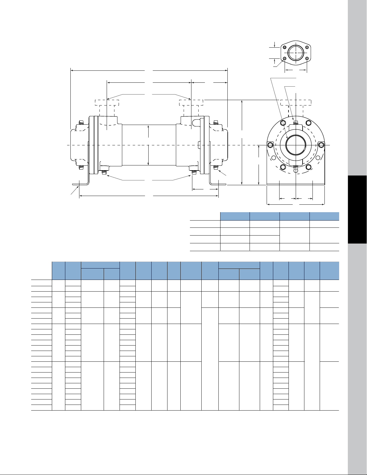
M
B
D
L
N
K
J
A
E
C
Q
P
P
H (2 each end)
GG
HH
Z (4 places)
F
G G
Dimensions
MODEL
B-401
B-402
B-701
B-702
B-703
B-1002
B-1003
B-1004
B-1202
B-1203
B-1204
B-1205
B-1206
B-1207
B-1208
B-1602
B-1603
B-1604
B-1605
B-1606
B-1607
B-1608
B-1609
B-1610
7.62
16.62
7.00
16.00
25.00
15.50
24.50
33.50
14.62
23.50
32.38
41.38
50.50
59.50
68.38
13.60
22.60
31.60
40.60
49.60
58.60
67.60
76.60
85.60
11.01
20.01
12.01
21.01
30.01
21.71
30.71
39.71
21.50
30.38
39.25
48.25
57.38
66.38
75.25
22.38
31.38
40.38
49.38
58.38
67.38
76.38
85.38
94.38
A
2.125
3.656
5.125
6.125
8.00
3.50
6.25
7.38
8.81
12.13
1.94
3.62
4.00
4.75
6.50
2.62
5.25
6.75
7.50
8.62
*.50
1.00
1.50
2.00
3.00
#8, 3/4-16
UNF-2B
#16,
1
5
/16-12
UNF-2B
#24,
17/8-12
UN-2B
#32,
21/2-12
UN-2B
—
.88
1.50
2.00
2.50
3.50
1.72
2.69
3.06
3.44
4.39
1.81
3.24
4.05
4.88
6.52
—
(4)
.38
(4)
.50
1.00
1.50
2.00
3.00
4.00
.41 Dia.
.44 x 1.00
.44 x .88
.44 x 1.00
—
(2)
.38
(6)
.38
—
C/F
8.46
10.50
15.61
B
NPT/BSPP
SAE O-RING
NPT/BSPP
FLANGE
SAE
FLANGE
D E F G H J
NPT
L
11.24
20.24
13.64
22.64
31.64
23.60
32.60
41.60
24.38
33.25
42.12
51.12
60.25
69.25
78.12
26.62
35.62
44.62
53.62
62.62
71.62
80.62
89.62
98.62
M N P
NPTQNPT
SAE
O-RING
C
K
One Pass
Flange Size GG HH Z - CF Z - CFM
1 1.03 2.06 3/8-16 UNC M-10
1.50 1.41 2.75
2 1.69 3.06
1/2-13 UNC M-12
3 2.44 4.19 5/8-11 UNC M-16
B-401 and B-402 SAE Flange not available. NOTE: We reserve the right to make reasonable design changes without notice. Consult factory. All dimensions are inches.
www.thermaltransfer.com TTPSales@thermasys.com 262.554.8330
WATER COOLED B
103
B
 Loading...