

Thermal Transfer Systems AOF User Manual
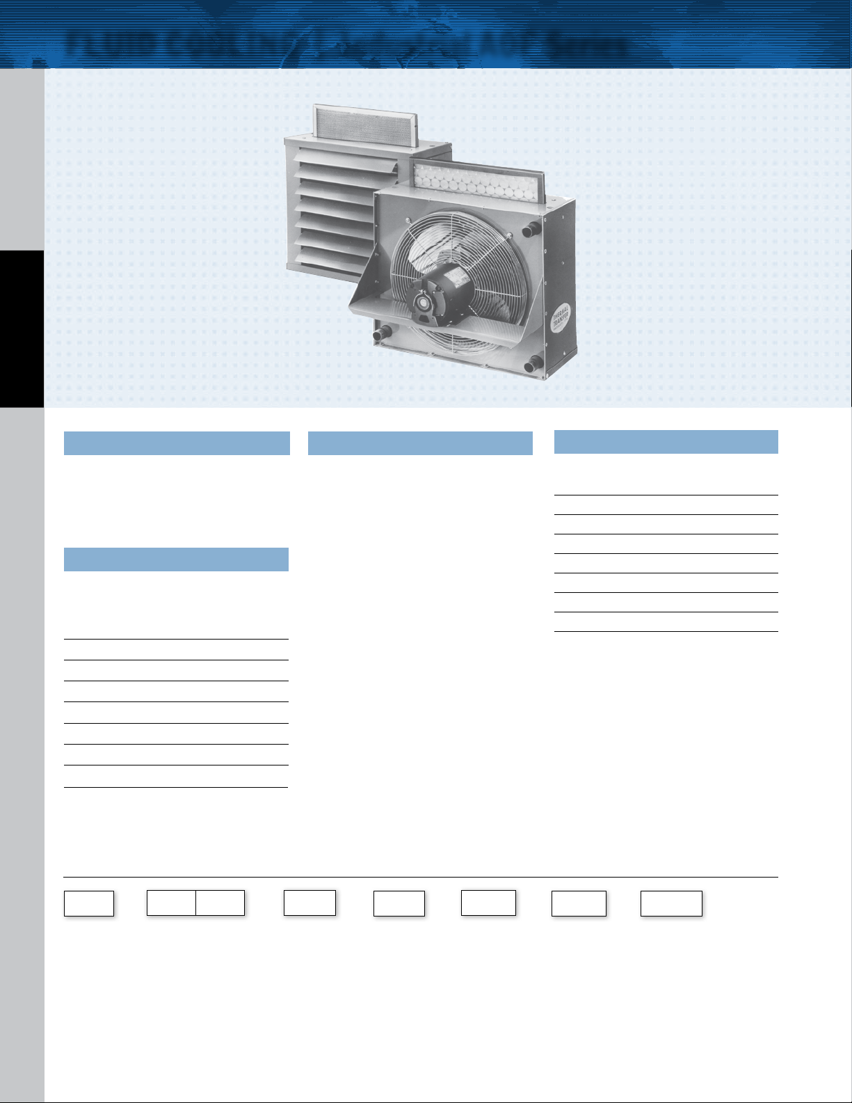
FLUID COOLING | Industrial AOF Series
FEATURES
n
AO with Removable Filter
n
Adjustable Louvers
n
Medium Flow Rates
n
Moderate Heat Removal
n
One or Two Pass Option
n
Fluid Power Systems
AIR COOLED AOF
n
Gear Drives
n
Injection Molding Machines
n
Machine Tools
n
Torque Converters
n
Hydraulic Presses
OPTIONS
SAE & Metric Connections
Built-in Bypass Relief
Foot Mounting Brackets
Corrosion Resistant/Marine
Duty Coating
Ratings
Operating Pressure - 300 psi
Test Pressure - 300 psi
Operating Temperature - 400° F
Replacement Air Filters
Fiberglass
Disposable Type
MODEL
Part Number
AOF - 5 65528 65559
AOF - 10 65530 65560
AOF - 15 65507 65561
AOF - 20 65532 65562
AOF - 25 6 5519 65563
AOF - 30 65535 65564
AOF - 35 65537 65565
AOF - 40 65543 65566
AOF
How to Order
Aluminum
Washable Type
Part Number
Materials
Tub es Copper
Fins Aluminum
Tur bul ato rs Steel
Fan Blade Aluminum with steel hub
Fan Guard Zinc plated steel
Cabinet Steel with baked enamel finish
Manifolds and Connection Pipes S t e e l
Weights
MODEL Net Weight (LBS)
AOF-5 60
AOF-10 70
AO F-15 80
AOF-20 95
AOF-25 125
AOF-30 14 0
AOF-35 165
AOF-40 230
–
Model
Series
AOF - No Bypass
AOFR - Includes
Bypass
*ADD FOR AOFR MODELS ONLY: Relie f Bypass Setting & Number of Passes
TTPSales@thermasys.com 262.554.8330 www.thermaltransfer.com
16
Model Size
Selected
–
Number of Passes*
Blank - No Byp ass
1 - One Pass
2 - Two Pass
– –
Connection
Type
Blank - NPT
S - SAE
M - Metric
–
Relief Bypass
Setting*
30-30 psi
60 - 60 psi
Foot Mounted
Brackets
Blank - No
Brackets
FB - Foot Brackets
–
Specify Mo tor
Required
Single Phase
Single Phase Expl. Proof
Three Phase
Three Phase 575 Volt
Three Phase Expl. Proof
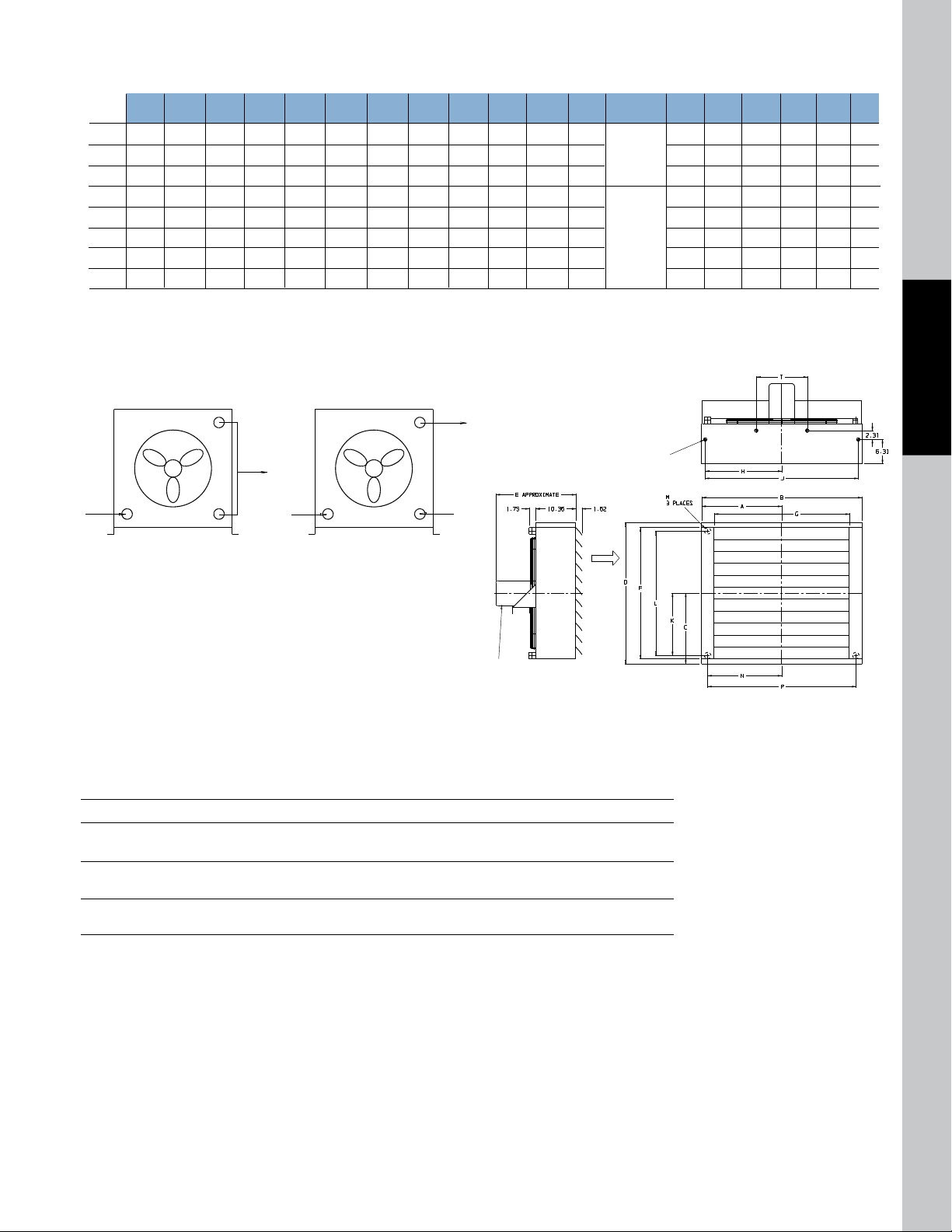
Dimensions
Model
A B C D E F G H J K L N P Q R S T
M
NPT M SAE
AOF-5 7.40 14.81 5.90 11.81 17.50 9.19 8.31 6.47 12.94 3.78 7.69 1”
#16 SAE
5.84 11.69 10.06 1.09 3.92 —
AOF-10 9.50 19.00 6.56 13.12 17.00 10.50 12.50 8.56 17.12 4.44 8.88 1”
1-5/16-12UN-2B 7.94 15.88 14.38 1.09 3.92 —
AOF-15 10.19 20.38 7.87 15.75 17.62 13.12 13.88 9.25 18.50 5.75 11.50 1”
Thread
8.62 17.25 15.62 1.09 3.92 —
AOF-20 11.91 23.81 9.19 18.38 19.62 15.75 17.91 10.90 21.81 7.00 14.00 1-1/4”
10.28 20.56 18.62 1.09 3.92 —
AOF-25 13.34 26.68 11.81 23.62 20.68 21.00 20.19 12.40 24.81 9.62 19.25 1-1/4”
#20 SAE
11.78 23.56 21.62 1.09 3.92 —
AOF-30 15.81 31.62 13.78 27.56 20.12 24.94 25.12 14.87 29.75 11.59 23.19 1-1/4”
1-5/8-12UN-2B
14.25 28.50 26.62 1.09 3.92 11.00
AOF-35 16.90 33.81 15.09 30.19 21.25 27.56 27.31 15.97 31.94 12.90 25.81 1-1/4”
Thread
15.34 30.69 28.88 1.09 3.94 11.00
AOF-40 20.81 41.62 18.37 36.75 20.31 34.12 35.12 19.87 39.75 16.19 32.38 1-1/4” 19.25 38.50 37.00 1.18 3.87 13.25
1/2-13 UNC-28
4 Places
8 Places on
AO-30, 35 & 40
(Top & Bottom)
AIR
FLOW
NOTE: MOTOR MOUNTING BRACKET ON
AO-5 & AO-10 IS ROTATED 90°
Oil
IN
Oil
OUT
Oil
IN
Oil
OUT
Oil
IN
Air
Cap
Oil
OUT
Installation Piping Diagram
One Oil Pass Two Oil Pas ses
*See dimension chart for NPT or optional internal SAE connection size.
NOTE: All dimensions in inches.
Fan Rotation Clockwise/Facing Motor Shaft
Lubrication Notes
Caution: Do not over oil or over grease. Ball bearings – No grease needed at start up. Grease as follows:
5,000 Hours/Year 5 Year Grease Interval
Continuous
Normal Applications
Seasonal Service
Motor is idle for 6 months or more
Continuous
High ambients, dirty or moist locations, high vibration
2 Years
1 Year
6 Months
AIR COOLED AOF
www.thermaltransfer.com TTPSales@thermasys.com 262.554.8330
17
AOF
 Loading...