

Page 1
FLUID COOLING | Industrial AOC Series
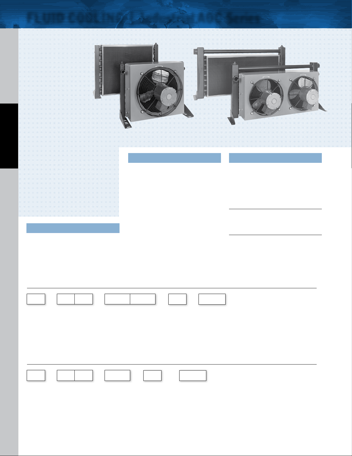
FEATURES
n
AC Motors
n
Core Filter
n
3/4” Tubes
n
Low Cost
n
Industrial Duty
n
Quiet Operation
AIR COOLED AOC
n
For Low Flow Rates
n
Oil Flows to 150 GPM
n
Mounting Brackets Included
n
SAE Connections
n
Single or Three-Phase 60/50 Hz
Motors
n
Filter Standard
OPTIONS
Built-in Serviceable Bypass Valve;
NPT or BSPP Oil Connections
Ratings
Operating Pressure - 300 psi
Test Pressure - 300 psi
Operating Temperature - 350° F
Materials
Tub es Copper
Fins Aluminum
Tur bul ato rs Aluminum
Fan Blade Aluminum with steel hub
Fan Guard Steel with black baked enamel finish
Cabinet Steel with baked enamel finish
Manifolds Copper: Model AOC-08
Steel: Models AOC-19 – AOC-70
Connections Brass: Model AOC-08
Steel: Models AOC-19 – AOC-70
Nameplate Aluminum
Filter Stainless frame with washable media
Relief Bypass Valve Option
MODEL DESCRIPTION
AOC-08 Available in one pass (30 and 60
AOC-19
thru
AOC-33
AOC-37
Thru
AOC-70
psi), two pass (60 psi), designs
only. Valves are built into tubes
and do not affect external
dimensions. All steel valves.
Non-serviceable.
Available in 30 psi or 60 psi
settings. 3/4”, external, all steel
valve. May be removed for
servicing.
Available in 30 psi or 60 psi
settings. 1-1/2”, external, all
steel valve. May be removed for
servicing.
How to Order (AOC-08 models only)
AOC 0 8
Model
Series
AOC - Standard
*Bypass not available in Four Pass
AOC
– – –
Model Size
Selected
Number of
Passes
1 - One Pass
2 - Two Pass
4 - Four Pass
Connection
Type
1 - NPT
2 - SAE
3 - BSPP
Relief Bypass*
Blank - No Byp ass
How to Order (Models AOC-19 through AOC-70)
AOC
Model
Series
AOC - Standard
TTPSales@thermasys.com 262.554.8330 www.thermaltransfer.com
4
– – –
Model Size
Selected
Connection
Type
1 - NPT
2 - SAE
3 - BSPP
Relief Bypass
Blank - No Byp ass
30 - 30 psi
60 - 60 psi
–
Specify Mo tor
30 - 30 psi
60 - 60 psi
115/230 V Single Phase
–
Specify Mo tor
Required
115/230 V Single Phase
208 -230/460V Three P hase
575 Volt
No Motor
Required
No Motor
Page 2
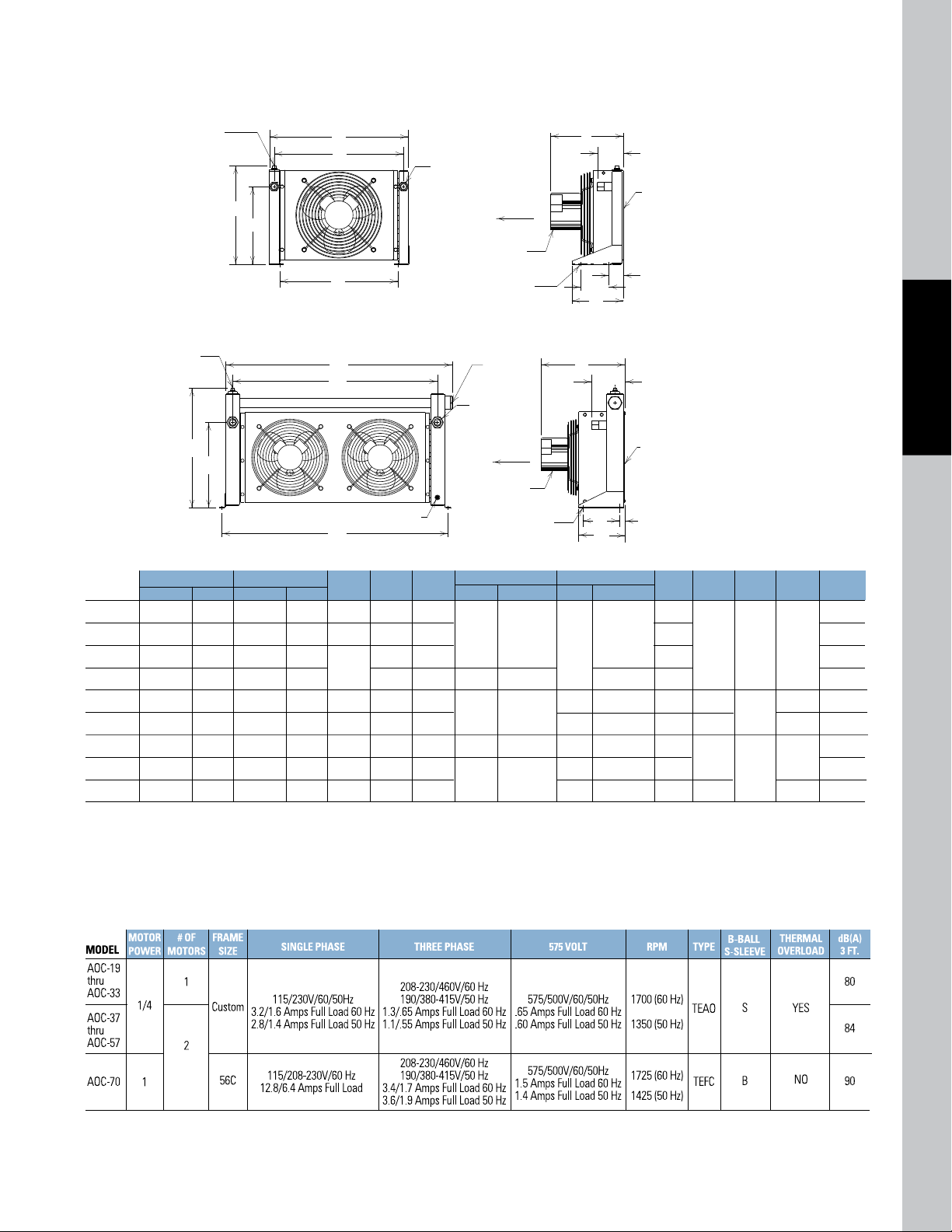
Dimensions
ELECTRIC
MOTOR
1/2 NPT
FOR OPTIONAL
TEMP. SENSOR
AIR
FILTER
SERVICEABLE
BYPASS VALVE
30 OR 60 PSI
3/8 NPT
DRAIN
.53 DIA HOLE
2 EACH BRACKET
AIR FLOW
J
M
P
F (2 PLACES)
B
E
H
A
D
C
G
MODELS AOC-37 THROUGH AOC-70
IN OUT
BypassNo Bypass
13.62
15.62
19.62
25.62
18.50
22.50
30.50
36.50
38.38
16.00
18.00
22.00
28.00
21.38
25.38
33.28
39.38
41.25
16.50
22.00
24.75
30.25
39.00
41.00
42.00
48.00
51.00
18.16
23.66
26.41
31.91
40.38
42.38
43.38
49.38
52.38
13.08
12.19
13.19
15.66
15.62
17.09
16.72
22.62
10.31
12.31
16.31
22.31
15.25
19.25
27.25
32.75
34.00
15.00
20.50
23.25
28.75
36.50
38.50
39.50
45.50
48.50
14.75
18.69
21.44
26.97
40.50
42.50
43.75
49.75
52.75
BypassNo Bypass
NPT & BSPP
SAE
MODEL
AOC-19
AOC-22
AOC-24
AOC-33
AOC-37
AOC-50
AOC-54
AOC-57
AOC-70
A B
C D E
G
#12
#16
#20
#24
#32
.75
1.00
1.25
1.50
2.00
NPT & BSPPSAE
3.05
4.62
4.68
4.89
6.68
8.44
2.61
1.06
1.12
1.87
1.62
5.00
6.50
9.00
8.18
8.31
8.37
12.37
12.12
4.12
4.34
5.97
6.03
6.30
8.15
9.91
F
H J M P
19
33
46
65
95
120
154
190
322
LBS
AIR FLOW
ELECTRIC
MOTOR
.41 X 1.19 SLOT
2 EACH BRACKET
1/2 NPT
FOR OPTIONAL
TEMP. SENSOR
C
G
AIR
FILTER
J
M
P
F (2 PLACES)*
B
E
H
A
D
MODELS AOC-19 THROUGH AOC-33
Models AOC-19 Through AOC-33
Models AOC-37 Through AOC-70
AIR COOLED AOC
NOTE: All dimensions in inches. We reserve the right to make reasonable design changes without notice.
*Inlet and outlet oil ports reversible if relief bypass option is not used.
Specifications
Electric Motor Data
NOTE: Amp ratings are per motor.
www.thermaltransfer.com TTPSales@thermasys.com 262.554.8330
5
AOC
Page 3

2.5
2
2.5
3
4
5
6
7
8
9
10
15
20
25
30
40
50
60
70
80
90
100
3 4 5 6 7 8 9 10 15 20 25 30 40 6050 100908070 200 250 300150
●
■
▲
✛
●
●
●
●
●
●
●
●
■
■
■
■
■
■
■
■
▲
▲
▲
▲
▲
▲
▲
▲
✛
✛
✛
✛
✛
OIL FLOW - G.P.M.
HORSEPOWER REMOVED IN COOLER
AOC-19
AOC-22
AOC-24
AOC-33
AOC-37
AOC-50
AOC-54
AOC-57
AOC-70
Oil ▲P
● = 5 PSI
■ = 10 PSI
▲ = 20 PSI
✛ = 40 PSI
50 60 80 100 150 300 400 500
3
2
1.5
1
.8
.6
OIL
P MULTIPLIER
OIL VISCOSITY - SSU
OIL
P CORRECTION CURVE
Selection Procedure
50 100 002 003 500
5
1
2
3
4
OIL P MULTIPLIER
OIL VISCOSITY - SSU
OIL
P CORRECTION CURVE
400
Performance Curves are based on 50SSU oil leaving the cooler 40°F higher
than the ambient air temperature used for cooling.This is also referred to as
a 40°F approach temperature.
STEP 1 Determine the Heat Load.This will vary with different systems,
but typically coolers are sized to remove 25 to 50% of the input
nameplate horsepower.
(Example: 100 HP Power Unit x .33 = 33 HP Heat load.)
If BTU/Hr. is known: HP =
BTU/Hr
2545
STEP 2 Determine Approach Temperature. Desired oil leaving cooler
AIR COOLED AOC
STEP 3 Determine Curve Horsepower Heat Load. Enter the
°F – Ambient air temp. °F = Actual Approach
information from above:
Horsepower heat load x
40 x Cv
= Curve Horsepower
Actual Approach
STEP 4 Enter curves at oil flow through cooler and curve horsepower.
Any curve above the intersecting point will work.
STEP 5 Determine Oil Pressure Drop from Curves:
l = 5 PSI; n = 10 PSI; s = 20 PSI; ; = 40 PSI. Multiply
pressure drop from curve by correction factor found in oil
correction curve.
Desired Reservoir Temperature
Return Line Cooling: Desired temperature is the oil temperature leaving the
cooler. This will be the same temperature that will be found in the reservoir.
Off-Line Recirculation Cooling Loop: Desired temperature is the oil temperature entering the cooler. In this case, the oil temperature change must be
determined so that the actual oil leaving temperature can be found.
Calculate the oil temperature change (oil
Oil
T = (BTU’s/Hr.) / (GPM Oil Flow x 210).
T) with this formula:
To calculate the oil leaving temperature from the cooler, use this formula:
Oil Leaving Temp. = Oil Entering Temp – Oil
T.
This formula may also be used in any application where the only temperature
available is the entering oil temperature.
Oil Pressure Drop: Most systems can tolerate a pressure drop through the
heat exchanger of 20 to 30 PSI. Excessive pressure drop should be avoided.
Care should be taken to limit pressure drop to 5 PSI or less for case drain
applications where high back pressure may damage the pump shaft seals.
Oil Temperature
P
Typical operating temperature ranges are:
Hydraulic Motor Oil 110° - 130°F
Hydrostatic Drive Oil 130° - 180°F
Bearing Lube Oil 120° - 160°F
Lube Oil Circuits 110° - 130°F
Performance Curves
AOC
TTPSales@thermasys.com 262.554.8330 www.thermaltransfer.com
6
De-rate cooler performance by 10%
when used in 50Hz service.
Page 4

1.5
2
3
4
5
6
8
10
15
20
1.5
1
.8
.6
7
.7
2.5
.9
●
■
HORSEPOWER REMOVED IN COOLER
OIL FLOW - GPM
8.31
9.41
2.31
1.50
.34 DIA. HOLE (BOTH SIDES)
AIR
FLOW
3/4" NPT,
#12 SAE,
or BSPP (2-PLACES)
12.25
11.12
7.50
9.19
.9 1
1.5
2
3
4
5
6
8
7
9
2.5
1.5
1
.6
.7
.8
.9
●
■
▲
HORSEPOWER REMOVED IN COOLER
OIL FLOW - GPM
9.41
.34 DIA. HOLE (
BOTH SIDES
)
8.31
9.50
AIR
FLOW
1/2" NPT,
#8 SAE,
or BSPP
(2-PLACES)
4.00
3.80
7.50
13.12
2.31
1.50
.5.4 .6 .7 .8 .9 1 1.5 2 2.5 3 4 5
1.5
1
.9
.8
.7
.6
●
■
▲
HORSEPOWER REMOVED IN COOLER
OIL FLOW - GPM
9.41
2.31
1.50
1.50
13.50
9.50
8.31
2.83
6.00
7.50
.34 DIA. HOLE (BOTH SIDES)
AIR
FLOW
1/2" NPT,
#8 SAE,
or BSPP
(2-PLACES)
MODEL
AOC-08
MOTOR POWER
1/30
115/230 VOLT
115 VOLT
230 VOLT
50/60 Hz
1.1 Amps Full Load
.7 Amps Full Load
RPM
3000
dB(A) 3 FT.
70
TYPE
TEAO
BEARINGS
B-BALL S-SLEEVE
S
THERMAL
OVERLOAD
YES
SHIPPING
WEIGHT (lbs.)
12
CV Viscosity Correction
OIL
SAE 5 SAE 10 SAE 20 SAE 30 SAE 40
Average
110 SSU at 100°F 150 SSU at 100°F 275 SSU at 100°F 500 SSU at 100°F 750 SSU at 100°F
Oil Temp °F
40 SSU at 210°F 43 SSU at 210°F 50 SSU at 210°F 65 SSU at 210°F 75 SSU at 210°F
100 1.14 1.2 2 1.3 5 1.5 8 1.7 7
150 1.01 1.05 1.11 1.2 1 1.3 1
200 .99 1.00 1.01 1.08 1.10
250 .95 .98 .99 1.00 1.00
AOC-08 Model Only
One Pass
AIR COOLED AOC
Two Pass
Four Pass
Specifications
Electric Motor Data
www.thermaltransfer.com TTPSales@thermasys.com 262.554.8330
7
AOC
 Loading...