

Page 1
®
INSTALLATmON iNSTRUCTIONS
MODEL WD24/WD27/WD30
WARMING DRAWER
PLEASE READ ENTtRE iNSTRUCTiONS BEFORE PROCEEDnNG.
iNSTALLATiON MUST COMPLY WITH ALL LOCAL CODES.
The warming drawer is completely self-contained and ready for installation.
Power Supply: 120Volts, 15 Ampere, 60 Hz.
iMPORTANT: Before turning on power, be sure that the control is turned to "OFF."
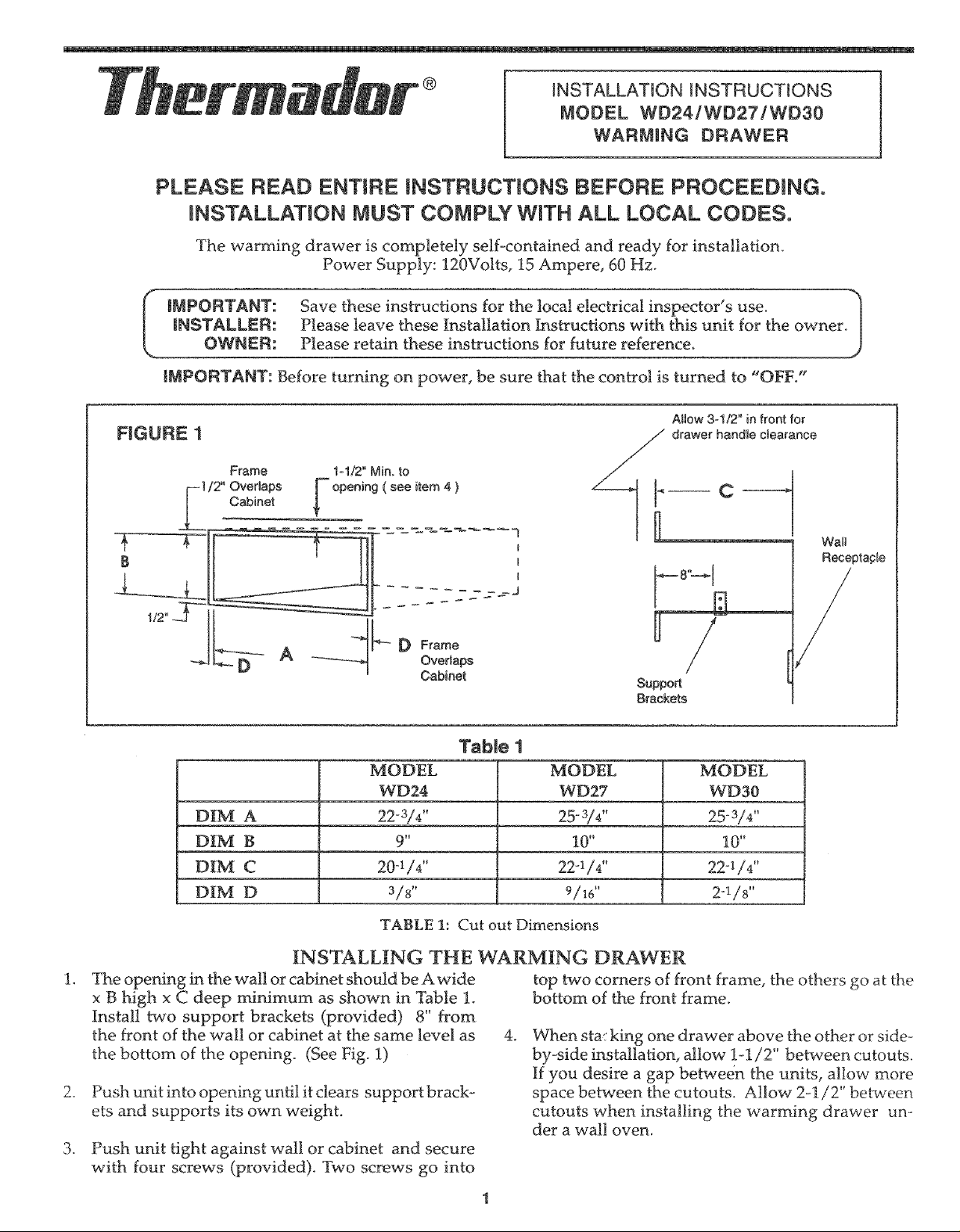
Allow 3ol/2" in front for
FIGURE 1
Frame 1ol/2" Min. to
Cabinet
drawer handle clearance
Support
Brackets
Table 1
MODEL MODEL MODEL
WD24 WD27 WD30
DIM A 22-3/4" 25-3/4" 25-3/4"
DIM B 9" 10" 10"
DIM C 20-1/4 '' 22°1/4"
DIM D 3/8" 9/lg' 2-!/8"
Wal_
Receptacle
TABLE 1: Cut out Dimensions
INSTALLING THE WARMING DRAWER
The opening ha the wall or cabinet should be A wide
x B high x C deep minimum as shown in Table 1.
Install two support brackets (provided) 8" from
the front of the wall or cabinet at the same level as
the bottom of the opening. (See Fig. 1)
.
Push unit into opening until it clears support brack-
ets and supports its own weight.
,
Push unit tight against wall or cabinet and secure
with four screws (provided). Two screws go into
top two corners of front frame, the others go at the
bottom of the front frame.
.
When sta: king one drawer above the other or side-
by-side installation, allow 1-1/2" between cutouts.
If you desire a gap between the units, allow more
space between the cutouts. Allow 2-1/2" between
cutouts when installing the warming drawer un-
der a wall oven.
Page 2
ELECTRICAL REQUIREMENTS & GROUNDING INSTRUCTIONS
THIS APPLIANCE MUST BE CONNECTED TO
RECEPTACLE ON A CIRCUIT RATED 120
VOLTS, 15 AMPERE, 60 Hzo
Always disconnect electric supply cord from wall
outlet before servicing this appliance.
Observe all governing codes and ordinances when
grounding. In the absence of these codes or ordi-
nances observe National Electrical Code ANSI/
NFPA No. 70 Current Issue.
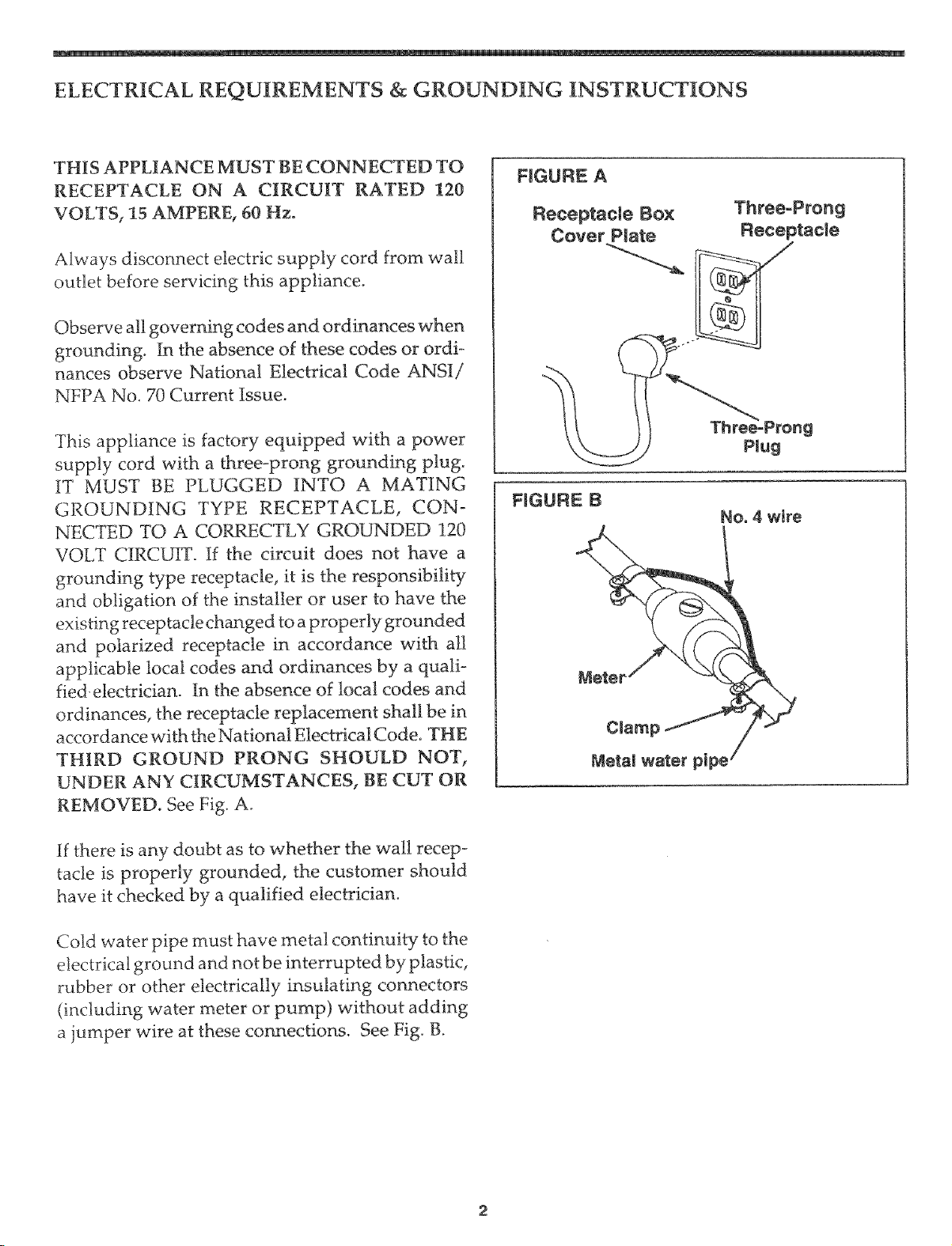
This appliance is factory equipped with a power
supply cord with a three-prong grounding plug.
IT MUST BE PLUGGED INTO A MATING
GROUNDING TYPE RECEPTACLE, CON-
NECTED TO A CORRECTLY GROUNDED 120
VOLT CIRCUIT. If the circuit does not have a
grounding type receptacle, it is the responsibility
and obligation of the installer or user to have the
existing receptacle changed to a properly grounded
and polarized receptacle in accordance with all
applicable local codes and ordinances by a quali-
fied electrician. In the absence of local codes and
ordinances, the receptacle replacement shall be in
accordance with the National Electrical Code. THE
THIRD GROUND PRONG SHOULD NOT,
UNDER ANY CIRCUMSTANCES, BE CUT OR
REMOVED. See Fig. Ao
FIGURE A
Receptacle Box Three-Prong
Cover Plate Fteceptacie
FIGURE B
No. 4 wire
if there is any doubt as to whether the wall recep-
tacle is properly grounded, the customer should
have it checked by a qualified electrician.
Cold water pipe must have metal continuity to the
electrical ground and not be interrupted by plastic,
rubber or other electrically insulating connectors
(including water meter or pump) without adding
a jumper wire at these connections. See Fig. B.
Page 3

PROCEDURE FOR CUSTOM WOOD DOOR FRONT
Construction of the Warming
Drawer door is such that, the
glass panel can be replaced with
a custom wood panel to match
other kitchen decor.
The glass panel can be replaced
with a custom panel. Remove
the drawer as noted in the Care
& Use manual. Remove six
screws securing the glass pack to
the front of the drawer from the
inside. Separate the glass pack
from the drawer°
Place the glass pack on a flat sur-
face (glass down) with the
handle overhanging the surface;
remove the two screw's securing
the handle. Once these screws
are removed, the glass panel can
be separated from the support.
Install the lens into the 1/2" di-
ameter hole at the bottom front
of the wood panel and press re-
tainer clip on back.
from damaging it. The custom
wood panel's dimensions are A
X B overall, Refer to Fig. 2 and
Table 2 for panel dimensions,
FIGURE 2
A
f-- Pilot Holes
1/2" Diameter Hole
Custom wood panel must be finished on aH4 edges
Changes in construction or
equipment may be made from
time to time by the manufacturer
without incurring any obliga-
tion.
for Lens ___4t_D-
TaNe 2
DiM.
WD 24
WD27
WD30
Attach the wood panel to the
support using two wood screw's
through the handle mounting
holes into the pilot holes on the
back side of the wood panel, Re-
assemble this support assembly
to the drawer replacing the six
screws. Then, install the drawer
back into the slides as noted in
the Care & Use Manual.
The custom wood panel must
have all four edges finished be-
cause they are exposed, The back
of the wood must be sealed to
prevent moisture in the drawer
B
C
D
E
23-1/2
10-1/4
1-1/4
1-1/4
1-5/16
F
2ol/4
26o7/8
11-1/4
I-1/4
I-3/8
3
2-1/4
29-7/8
! 1-1/4
1-1/4
2-7/8
4-1/2
2-1/4
Page 4

Specificationsare forp_anningpurposes only.Referto installationinstructionsand consultyour eountertop suppHierpriorto
making counter opening. Consubt with a heatingand ventilatingengineer for your specificventiSationrequirements. For the
most det_{led{nformation,referto installationinstructionsaccompanying product or write Thermador indicatingthe model
number.
Thermador reservesthe righttochange specificationsor designwithout notice.Some models are certifiedfor use inCanada.
Thermador isnot responsib[efor products which _re transportedfrom the United Statesfor use in Canada. Check with your
local Canadian distributor or dealer. Thermador, SSS I McFadden Avenue, Huntington Beach, CA 92649.
C
UL LISTED #157 JF_LED#E521958
_®
5551 McFadden Avenue, Huntington Beach,CA 92649 o800/735-4328
@ 2002 BSH Home Appliances Corp. • Litho U.S.A.05/02
50 60 0008 85 (8205)
4
 Loading...