

Page 1
INSTALLATION INSTRUCTIONS
ROOF OR WALL VENTILATOR
MODEL VTR1400Q, VTR1000Q & VTR600R
PLEASE READ ENTIRE INSTRUCTIONS BEFORE PROCEEDING.
IMPORTANT: Save these instructions for the Local Electrical Inspector’s use.
INSTALLER: Please leave these Installation Instructions with this unit for the owner.
OWNER: Please retain these instructions for future reference.
IMPORTANT SAFETY INSTRUCTIONS
SAFETY WARNING: Before servicing or cleaning unit, switch
power off at the service panel and
lock service disconnecting means to
prevent power from being switched
on accidentally. When the service
disconnecting means cannot be
locked, attach a tag to the service
panel to indicate power has been
switched off for maintenance.
WARNING - TO REDUCE
THE RISK OF FIRE, ELECTRIC
SHOCK, OR INJURY TO PERSONS, OBSERVE THE FOLLOWING:
A. Installation work and electrical wir-
ing must be done by qualified
person(s) in accordance with all
applicable codes & standards, including fire-rated construction.
B. Sufficient air is needed for proper
combustion and exhausting of gases
through the flue (chimney) of fuel
burning equipment to prevent back
drafting. Follow the heating equipment manufacturers guideline and
safety standards such as those published by the National Fire Protection Association (NFPA), and the
American Society for Heating, Refrigeration and Air Conditioning En-
gineers (ASHRAE), and the local
code authorities.
C. When cutting or drilling into wall or
ceiling, do not damage electrical
wiring and other hidden utilities.
D. To properly exhaust air, be sure to
duct air out side. Do not vent
exhaust air into spaces within walls,
ceilings, attics, crawl spaces, or garages.
WARNING: To reduce the risk of
fire, use only metal ductwork.
CAUTION - For General Ventilating Use Only. Do Not Use To
Exhaust Hazardous Or Explosive
Materials And Vapors.
READ AND SAVE THESE INSTRUCTIONS
Recommended for use only over conventional domestic gas and electric ranges, and
use with an approved Thermador Hood.
I. INSTALLATION:
1. Remove and discard shipping bracket (attached to motor mounts and inlet collar). Check to see if blower
wheel turns freely. Do not replace top until installation
is complete.
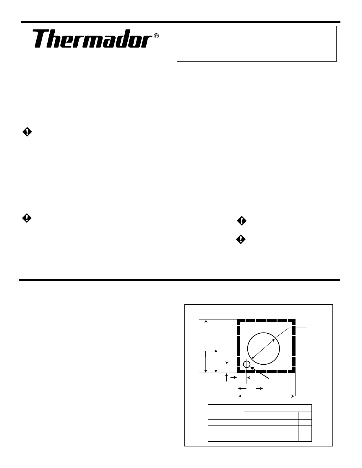
2. Provide a square cutout through the roof (or wall) as
shown by the dashed lines, or cut a round hole to fit duct
with a separate hole for electrical conduit as shown by
solid lines in Fig. 1.
3. Install the remote ventilator with the discharge pointing
down slope as shown in Figures 3 and 4. Follow standard
roofing procedures. Install the ventilator so the discharge edge is on top of the shingles and the rear edge
is underneath the shingles.
Fig. 1 TOP VIEW Down Slope of Roof or Wall
14"
B
1"
1"
A
Model A B C
VTR600R 5-11/16" 6-1/8" 9"
VTR1000Q 7-1/4" 6-15/16" 11"
VTR1400Q 7-1/4" 6-15/16" 11"
1
1-1/4 "
Hole
14"
Dim.
C Dia.
Page 2
12
12
12
12
12
12
12
12
12
12
12
12
12
12
12
12
12
12
12
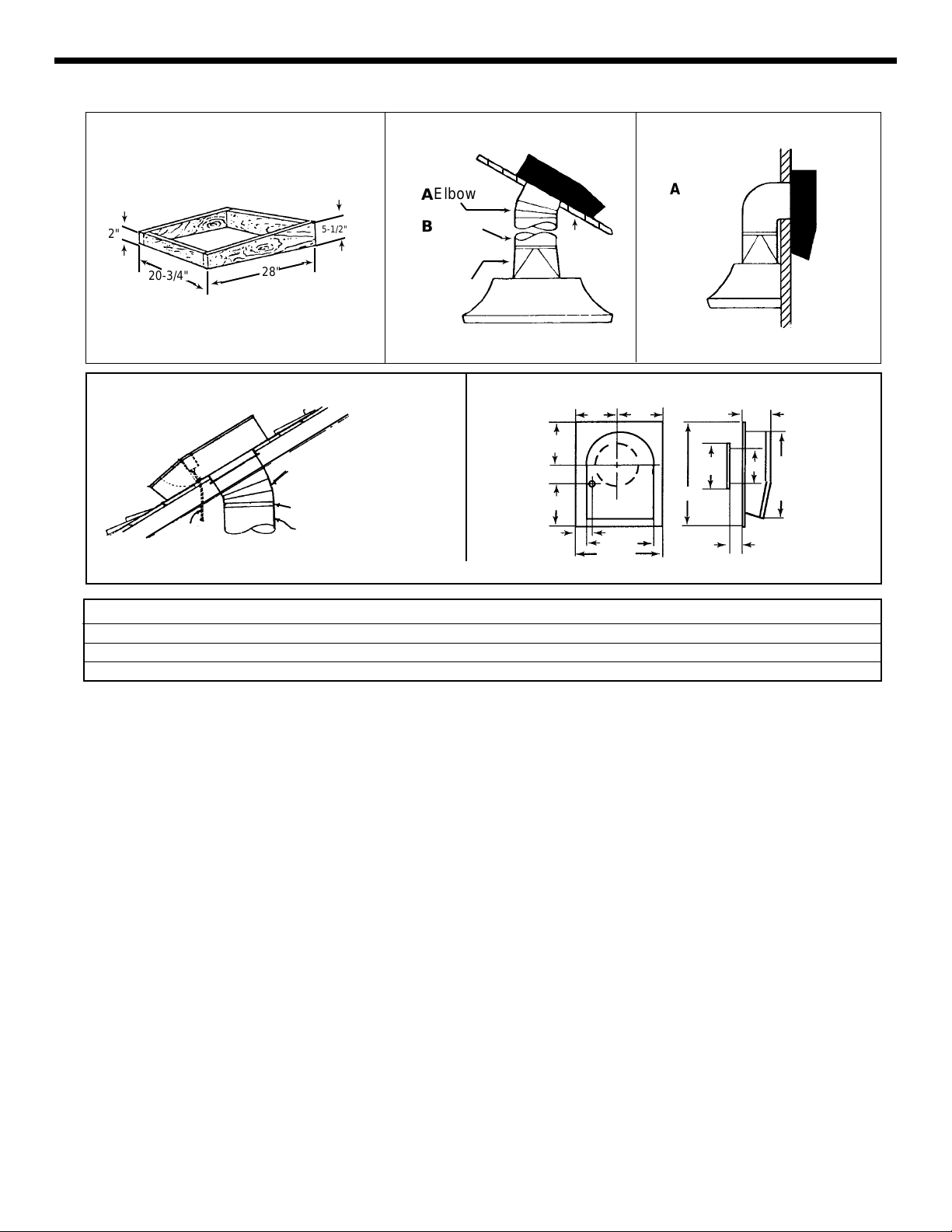
Figure 2 CURB FOR ROOF
➛
2"
➛
➛
20-3/4"
➛
➛
28"
➛
➛
5-1/2"
➛
Figure 3 Figure 4
Elbow
Elbow
A
A
➛
Round
B
Duct
Roof
➛
➛
➛
Roof
Transition
Transition
➛
➛
➛
Outside
Wall
Figure 5
Figure 6 – Remote Blower Dimensions
11-3/8"
9-3/8"
5-7/8"
C
G
H
I
J
Conduit
(Not Provided)
A Adjustable Elbow
Tape Joints
B Dia. Duct Conduit
D
E
F
20-3/4"
28"
TYPICAL INSTALLATION USING THERMADOR HOODS
MODEL A B C D E F G H I J
VTR1000Q 10" Dia. 10" Dia. 10-3/4 10-1/4 3-1/8 17-5/8 10-3/4 10 26-1/4 4
VTR1400Q 10" Dia. 10" Dia. 10-3/4 10-1/4 3-1/8 17-5/8 10-3/4 10 26-1/4 4
VTR600R 8" Dia. 8" Dia. 10-3/8 11-1/2 4-5/8 14-7/8 8-3/4 8 24 3-1/2
NOTE: The unit must be sealed between the roof (or
wall) and the underside of the flange with roofing mastic
to prevent leaks. For installation on a flat roof, or roofs
with a pitch less than 1-1/2" in 12", install ventilator on
the curb as shown in Fig. 2. Position the curb on flat roofs
so that the discharge (low) end points away from
prevailing wind.
3. Connect ventilator to the exhaust system with 8 inch
dia. duct for VTR600R and 10" dia. duct for VTR1000Q
and VTR1400Q. Use adjustable elbow to adjust to roof
angle. Tape all joints to prevent air leaks.
4. Connect ducting in the inlet to the ventilator with duct
tape.
5. Clearance to combustible material is 0".
II. FOR WIRING TO ALL APPROVED
®
THERMADOR
PRODUCTS, USE INSTALLATION INSTRUCTIONS PROVIDED WITH
THAT PRODUCT.
III. WIRING TO A WALL MOUNT 4 POSITION
VENTILATOR SPEED CONTROL SWITCH:
1. Use Thermador 4 position ventilator speed control
model CTR3Q (purchased separately).
2. Power supply required for these ventilators is
15 amps. @120V. AC, 60 Hz. connected per local
codes.
3. Run three (3) #14 AWG. wires (black, white and
green) from the power supply at the electrical
circuit panel to the wall box. See Figure 8.
4. Run electrical conduit per local code to conduit
outlet in bottom of ventilator as shown in Fig. 5.
Other end of conduit will connect to wall box with
4 position switch. See Figure 8.
5. Run five (5) #14 AWG. wires in conduit between
Ventilator J-box and 4 position switch. Use color
coded wire corresponding to colors shown in
Figure 8.
6. Use wire nuts to connect wires as shown in
Figure 8.
2
Page 3

IV. FOR WIRING TO A WALL MOUNT INFINITE
VENTILATOR SPEED CONTROL SWITCH
MODEL VTR600R ONLY:
1. Use Thermador infinite speed control switch model
#SSC1C (Purchase separately).
2. Power supply required for these ventilators is
15 amps. @120V. AC, 60 Hz. connected per local codes.
3. Run three (3) #14 AWG. wires (black, white and green)
from the power supply at the electrical circuit panel to
the wall box. See Figure 9.
4. Run electrical conduit per local code to conduit outlet
in the bottom of ventilator as shown in Figure 5.
Connect other end of conduit to wall box with speed
control switch as shown in Figure 9.
5. Run three (3) #14 AWG wires in conduit between
VTR600R and the infinite ventilator speed control switch.
Use color coded wire corresponding to wire colors
shown in Figure 9.
6. Use wire nuts to connect wires per Fig. 9 wiring diagram.
NOTE: There should be two (2) excess wires (blue and red)
from the motor. These wires are not needed for
wiring to this infinite ventilator speed control switch.
These wires should be individually capped with wire
nuts and pushed back inside the wiring compartment
on the remote ventilator VTR600R.
Fig. 7
WARNING:
Disconnect power before installing switch. Before turning
power on, be sure that all controls are in the OFF position.
1/2" Thin Wall Conduit
Ventilator Wall Switch
Model CTR3Q or SSC1C (VTR600R Only)
(Not Provided)
Fig. 8
Power Supply
120 V. 60 Hz.
Fig. 9
VTR600R/VTR1000Q/VTR1400Q: WIRING DIAGRAM FOR WALL MOUNT FOUR (4) POSITION
SWITCH MODEL # CTR3Q
White (Common)
Motor
Switch
3
2
1
CTR3Q
Black
VTR600R ONLY: WIRING DIAGRAM FOR WALL MOUNT INFINITE SWITCH MODEL #SSC1C
L1
White
Black
Blue
Red
Green
(Common)
(Hi)
(Med)
(Low)
(Ground)
in
Blower
Unit
VTR600R
VTR1000Q
VTR1400Q
White (Common)
Motor
in
Blower
Unit
VTR600R
ONLY
Power Supply
120 V. 60 Hz.
Black
Black
Switch
SSC1C
Black
White
Black
Green
(Common)
Blue
Red
(Ground)
3
Page 4

Installation must comply with all local codes
KITCHEN VENTILATION TIPS
6. WARNING - TO REDUCE THE RISK
OF A RANGE TOP GREASE FIRE:
1. Cooking Appliances such as Ranges, Cooktops, Barbecue Units, Grills, etc., require adequate ventilation. Hood
should be large enough and Cooking Appliances located
so that the Hood overhangs the Cooking Surface as much
as possible.
2. Consult a Competent Kitchen Designer or Ventilation
Engineer for proper Hood size and C.F.M. requirements.
3. Provide make-up air input to the kitchen so exhausted air
is not drawn through furnace unit or down fireplace
chimney.
4. Locate the Cooking Area for minimum cross drafts, away
from doors and windows, etc., when possible.
5. For best performance duct runs should be as short and
as straight as possible. Where turns are necessary, keep
turning radius as large and as smooth as possible.
a) Never leave surface units unattended at high set-
tings. Boil-overs cause smoking and greasy spillovers
that may ignite. Heat oils slowly on low or medium
settings.
b) Always turn hood ON when cooking at high heat or
when cooking flaming foods.
c) Clean ventilating fans frequently. Grease should not
be allowed to accumulate on fan or filter.
d) Use proper pan size. Always use cookware appro-
priate for the size of the surface element.
Thermador reserves the right to change specifications or design without notice. Some models are certified for use in Canada. Thermador is not responsible for products which are transported from the United
States for use in Canada. Check with your local Canadian distributor or dealer. Thermador , 5551 McFadden
Avenue, Huntington Beach, CA 92649.
For the most up to date critical installation dimensions by fax, use your fax handset and call 702/833-
3600. Use code #8030.
5551 McFadden Avenue, Huntington Beach CA, 92649 • 800/735-4328
UL LISTED #157J FILE # E521958
ECO 71566 19-12-182H • © Thermador Corporation, 1998 • Litho in U.S.A. 11/00
4
 Loading...