

Page 1

234
27" “S” OVEN VENT CONVERSION KIT 35-00-624
UPPER OVEN
LOWER OVEN
OFF
STOP
COOK
3
1
2
BAKE OFF
BAKE
TIME
TIME
SELF
SELF
BROIL
BROIL
TIMER 2
TIMER 1
4
5
6
CLEAN
CLEAN
CONVECTION
CONVECTION
OVEN
CONVECTION
CLOCK
CONVECTION
9
8
7
ROAST
ROAST
LIGHT
0
Models:
SCD272T
SC272T
S272T
234
INSTALLATION INSTR UCTIONS
FOR THERMADOR® BUILT-IN ELECTRIC OVENS
This conversion kit instructs the service technician on how to convect the upper and
lower plenum body to our redesign vent system.
5551 MCFADDEN • HUNTINGTON BEACH, CALIFORNIA 92649 • TELEPHONE: 800 /735-4328
ECO 11886 -02 • Lit. No. 96-93-563C
January 1999
1
Page 2
THESE KITS WILL BE COMPRISED OF THE FOLLOWING:
Quantity Description Part Number
1 Upper V ent T ube 16-10-058
1 Lower V ent Tube 16-10-059
2 Insulation 14-38-692
2 Templets (Inside of Instructions)
8 Screws 14-91-102
1 Kit Instructions 96-93-563 Rev A
1 Bracket Blower Mounts 14-38-482-01
NOTE: THE OVEN WAS SHIPPED WITH THE THERMOSTAT ADJUSTED AT +25 DEGREES.
WITH THE NEW UPWARD VENT, THE OVEN NEEDS TO BE CALIBRATED TO ZERO.
INSTRUCTIONS, TAKEN FROM THE C ARE AND USE MANUAL, ARE FOUND ON PAGE 20
OF THIS PUBLICA TION.
W ARNING
Turn of the electrical power circuit to the
oven at the main junction box, before
servicing this unit.
TO CONVERT THE UPPER OVEN CELL
REMOVE OVEN FROM WALL:
1) TURN OFF ELECTRICITY AT CIRCUIT BREAKER.
2) REMOVE MOUNTING SCREWS FROM CABINET.
3) DISCONNECT ELECTRICAL CONNECTIONS.
4) REMOVE OVEN DOORS. Figure 1.
5) REMOVE OVEN FROM WALL AND PLACE ON DOLLY OR PROTECTED FLOOR.
FIGURE 1.
When you work on the oven, be careful
when handling the sheet metal parts. There
are sharp edges present and you can cut
yourself if you are not careful.
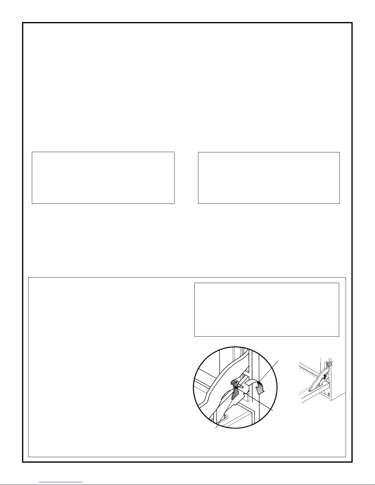
WARNING
With the door off, never release the levers
CAUTION
To Remove the Oven Door
1. Fully open the oven door.
2. Raise the U-clip over the hook on each of the
hinges to the “locked” position (see illustration
below). This will prevent the hinge from snapping closed when the door is removed.
3. Grasp the door by the sides toward the back.
Raise the front of the door sev eral inches (there
will be some spring resistance to over come because of the hinge being locked). When the fr ont
of the door is high enough, you will be able to
lift the hinges to clear the indents.
and try; to close the hinges. Without the
weight of the door, the powerful springs will
snap the hinges closed with great force.
Latch Hinge
Lower
Clip
After
Door is
Replaced
Hinge Arm
4. Pull the hinges out of the slots in the oven fr ont
frame.
Raise Clip to “Locked Position
to Remove Door
2
Page 3
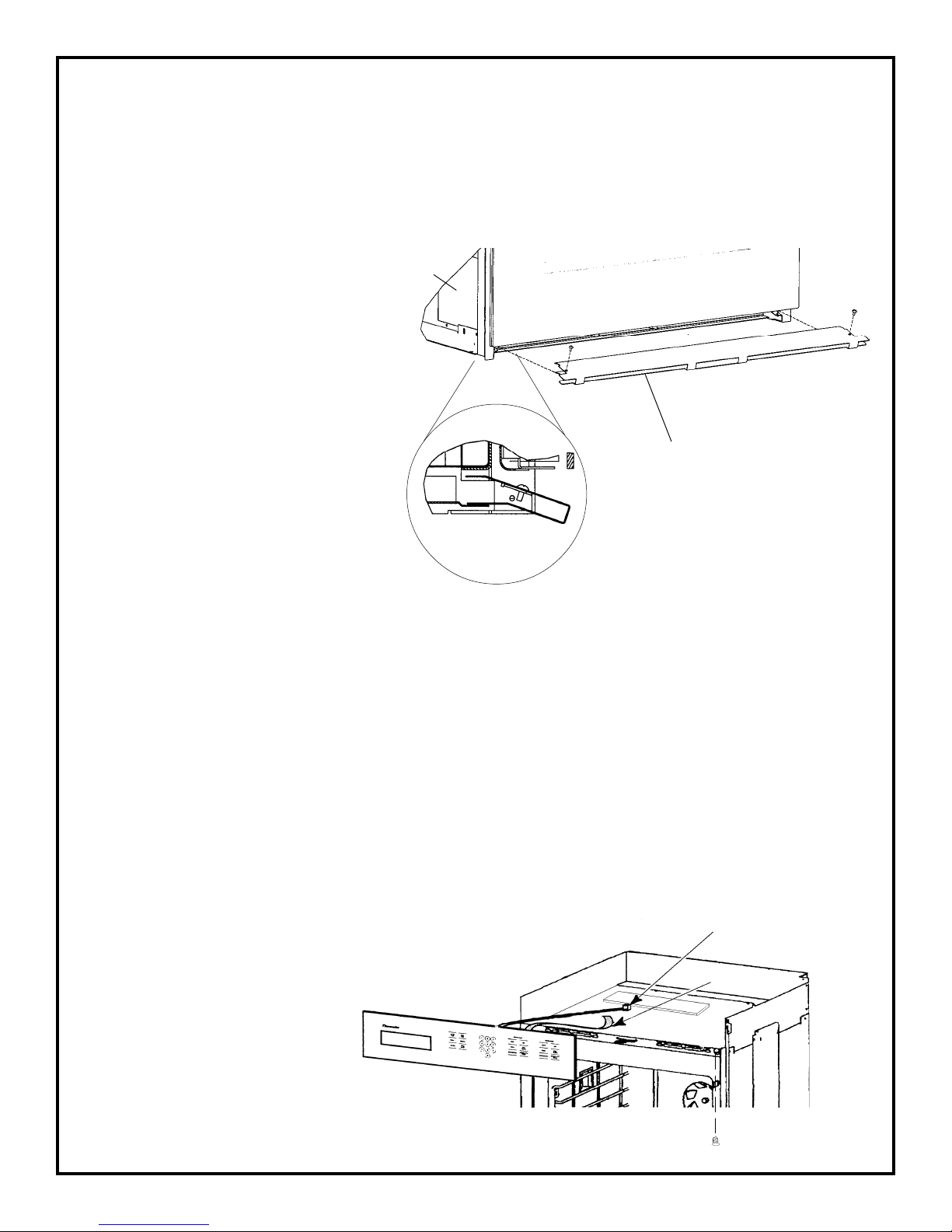
REMOVE FRONT OVEN TRIMS:
1) REMOVE BOTTOM TRIM (4 screws).
2) REMOVE SIDE TRIMS (4 screws on each trim).
Remove the two screws from
the bottom trim, pull it forward
and remove it.
Install the lower vent trim and
secure with (2) screws pr ovided,
one at each top end corner of
the trim. The sheet metal bottom of the oven should be under the trim, except for the section at the center. To install the
screws, open the door. The
holes are visible at each end below the left and right hinges.
Place and tighten screws.
See Fig. 2 View 'A'.
FIGURE 2.
Side
Trim
Side View
'A'
Bottom T rim
View 'A'
3) REMO VE CONTROL P ANEL. (4 scr ews) REMO VE RIBBON A T T OUCH CONTROL
BOARD. DISCONNECT PLUG P2 AT TOUCH CONTROL BOARD.
a) Remove the scre ws fr om the bottom of
the control panel frame and pull the top
of the panel forward to unsnap it from
the subpanel.
NOTE: To remove the ribbon cable fr om the
relay boar d connector , lift the ends of the locking strip and raise the strip, then remove the
end of the ribbon cable.
b) Disconnect the ribbon cable and plug, and
remobe the panel.
Figure 3
Connectors Plug P2
Ribbon Cable
Bottom Screw
3
Page 4
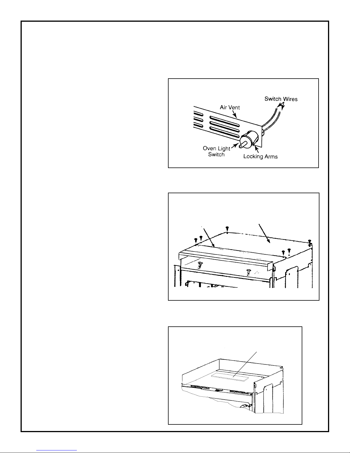
4) REMOVE FRONT VENT COVER. (4 screws)
REMOVE THE 2 LIGHT SWITCH WIRES. See Figure 4
a) Remove the air vent by removing the
two bottom screws and the two front
FIGURE 4.
oven door latch screws. Pull the vent
forward and unsnap it from the oven.
b) To remove the o ven light switch, remo ve
the wires from the terminals, then press
in on the locking arms, and push it out
of the hole in the vent.
5) REMOVE 2 FRONT SCREWS
THA T HOLD PLENUM T O O VEN
FIGURE 5
CAN. See Figure 5.
6) REMO VE TOP FRONT CO VER. (5
screws)
Front Plenum
Cover
7) REMOVE TOP REAR COVER. (10
screws)
Back Plenum
Cover
8) REMOVE THE HEAT SHIELD
PANEL WITH INSULATION
AND DISCARD.
FIGURE 6
Heat Shield
➛
4
Page 5
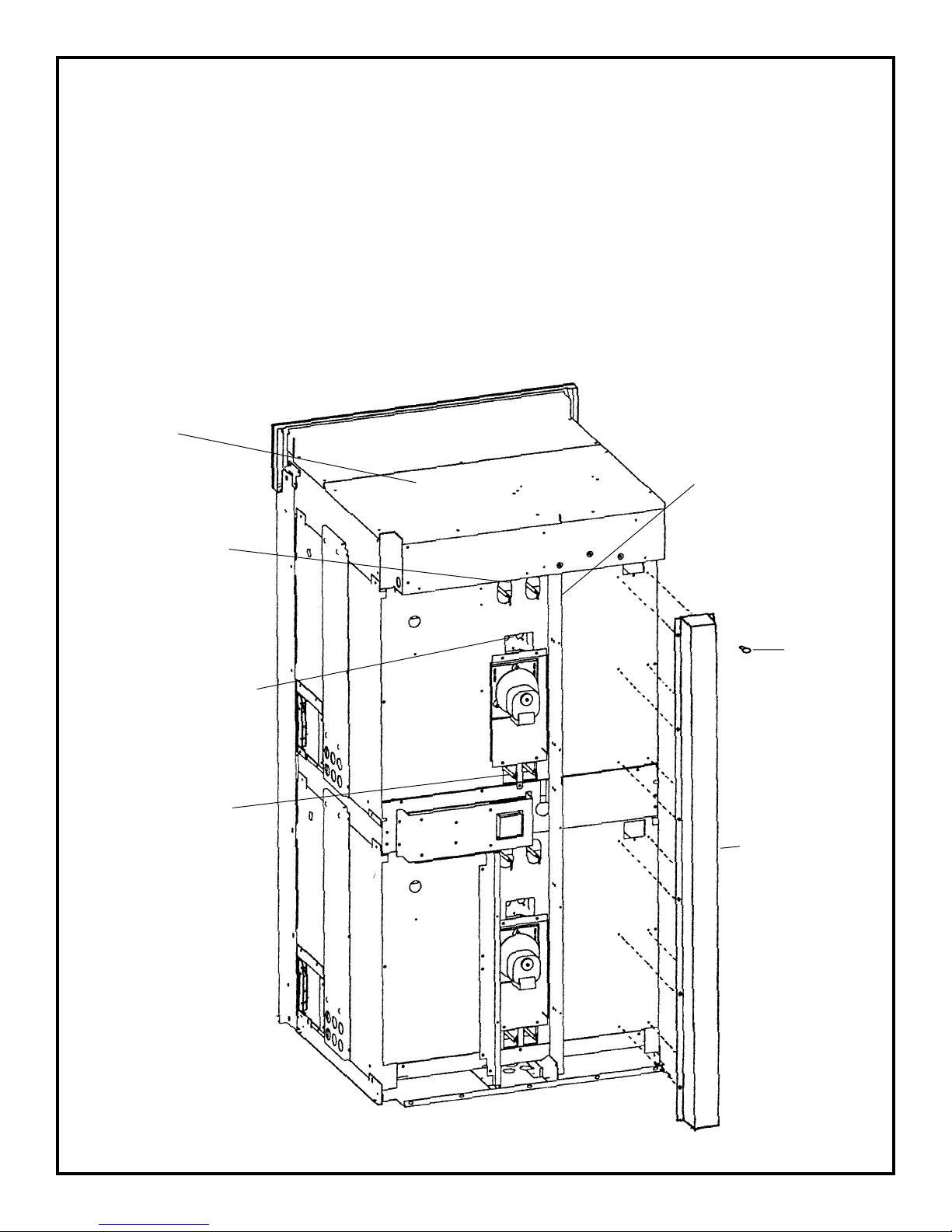
REMOVE REAR OVEN PANELS:
1) REMOVE REAR COVER. (20 screws)
2) REMOVE TOP OVEN VERTICAL VENT TUBE. ( 10 screws). See Figure 7.
3) REMOVE VERTICAL CHANNEL SUPPORT. (10 screws). See Figure 7.
4) REMOVE (5) RED WIRE TIES. ❋
5) REMOVE WIRE HOLDER. ✫
6) DISCONNECT WIRES AT BROIL ELEMENT.
7) DISCONNECT WIRES AT CONVECTION MOTOR.
FIGURE 6
Top Plenum
Broil Element Wires
Convection Motor Wires
Bake Element Wires
➛
➛
➛
✫
✫
➛
❋
❋
❋
❋
Vertical Channel Support
➛
Screws (10)
➛
V ertical V ent T ube
❋
✫
5
Page 6
PREPARE OVEN PLENUM FOR CONVERSION:
1) REMOVE BLOWER AND BLOWER BRACKET FROM PLENUM.
(bracket must be changed).
Remove the three screws 3, 4 and 5 that mount the
motor to the bracket. See Figure 8.
FIGURE 8. LOWER BLOWER BRACKET
Blower Bracket
Remove the three screws from the blower motor bracket on the back of the plenum
and turn the assembly around so thhat the back faces you. See Figure 9.
FIGURE 9. BACK OF PLENUM
Mounting Bracket
Screw
Lt Blue (97)
Screw
White (98)
White (24)
Screw
Upper Blower
Dk Blue
(23)
6
Page 7

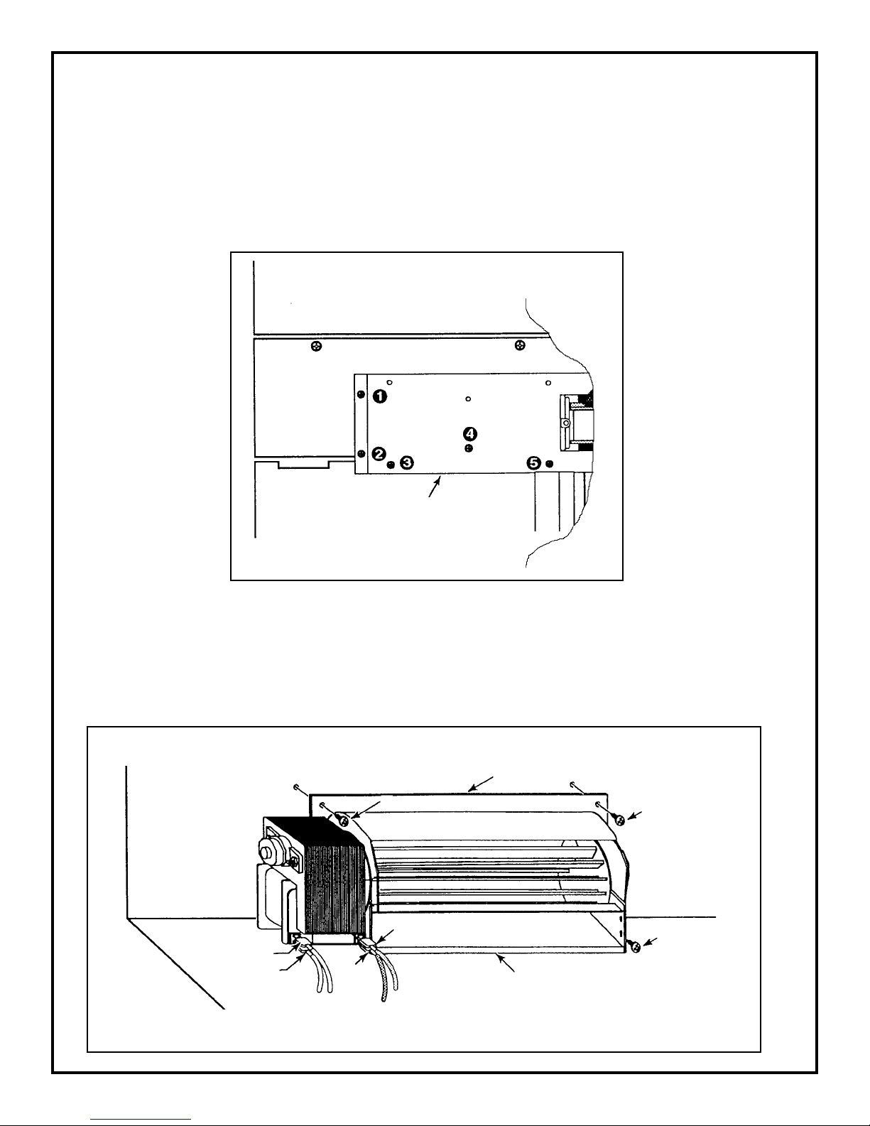
2) PLACE TEMPLATE ON PLENUM AND MARK, PUNCH AND DRILL HOLES.
FIGURE 10.
Template Location
Top Vent Hole Detail
(See Top Template)“A” Page 8.
FIGURE 11.
See Detail “B” Figure 12, for
Blower Mounting Hole
Modification
3) INSTALL NEW BRACKET AND REINSTALL BLOWER.).
Install the new blower in the mounting bracket and mount the assembl;y to the plenum.
FIGURE 12. – DETAIL “B”
Drill relieve or file holes to clear screw
heads on blower bracket
Drill three 3/16" diameter holes, 1/4"
directly below existing mounting holes
7
Page 8

“A”
8
Page 9

REMOVE TOP PLENUM:
1) REMOVE 4 SIDE SCREWS ON EACH SIDE THAT ATTACH THE PLENUM TO THE TOP OVEN
CAN CELL.
2) LIFT THE PLENUM UP AND SECURE THE NEW VENT AND INSULA TION TO THE UNDERSIDE
OF PLENUM WITH THE 4 TOP SCREWS PROVIDED.
3) LIFT THE PLENUM AND SLIDE IT FORWARD, IT IS NOT NECESSARY TO REMOVE THE
PLENUM OFF OF THE UPPER CAN CELL.
FIGURE 13.
New Insulation
Top Plenum
New V ent
(4) T op screws
➛
➛
➛
(4) Side Screws
9
Page 10

TO CONVERT TOP OVEN CELL:
1) REMOVE SCREW IN REAR OF PLENUM THAT HOLDS VENT TUBE TO OVEN WRAPPER.
2) REACH UNDER INSULATION BLANKET AND PULL VENT TUBE UP AND OUT OF CATAL YST.
3) SLIDE PLENUM OVER TOP OF O VEN CELL AND LINE UP NEW VENT TUBE WITH CA T ALYST .
FIGURE 14.
Rear Screw
“Old “ V ent Tube
(Pull up)
➝
➛
➛
Catalyst
4) SECURE PLENUM TO TOP OVEN CELL.
5) COVER SQUARE HOLE FOR OLD VENT TUBE WITH ALUMINUM TAPE. SEE FIGURE 15.
FIGURE 15.
➛
(Line Up)
Plenum
➛
Square Hole With
Aluminim T ape
10
Page 11

TO REMOVE THE TOP OVEN CELL FROM MID PLENUM:
1) DISCONNECT THE 2 LIGHT HARNESS PLUGS.
2) DISCONNECT UPPER AND LOWER PROBE HARNESSES AT THE RELAY BOARD.
3) DISCONNECT WIRES AT BAKE ELEMENT.
4) REMOVE 4 SCREWS ON EACH SIDE THAT ATTACH THE TOP OVEN CAN CELL TO THE
MID PLENUM.
5) REMOVE 4 SCREWS IN REAR THAT ATTACH THE TOP OVEN CAN CELL TO THE MID
PLENUM.
6) LIFT THE TOP OVEN CAN CELL OFF OF THE MID PLENUM.
FIGURE 16.
(Relay Board)
Inside
Top Oven
Can Cell
Side Screws
Lift Up
Rear Screws
11
Page 12

PREPARE MIDDLE OVEN PLENUM FOR CONVERSION:
1) REMOVE BLOWER AND BLOWER BRACKET FROM PLENUM. (bracket must be changed).
Remove the three scr ews 3, 4 and 5 that mount the motor to the
bracket. See Figure 17.
FIGURE 17. LOWER BLOWER BRACKET
Blower Bracket
Remove the three scr ews fr om the blow er motor brack et on the back of the plenum and
turn the assembly around so thhat the back faces you. See Figure 18.
FIGURE 18. BACK OF PLENUM
Mounting Bracket
White (98)
White (24)
Screw
Lt Blue (97)
Upper Blower
Screw
Screw
Dk Blue
(23)
12
Page 13

2) PLACE TEMPLATE ON PLENUM AND MARK, PUNCH AND DRILL HOLES.
FIGURE 19
See Detail “C” for
Blower Mounting
Hole Modification
➛
Template Location
Middle Vent Hole Detail
(See Middle T emplate “B”)
3) INSTALL NEW BRACKET AND REINSTALL BLOWER.
Install the new blower in the mounting bracket and mount the assembl;y to the plenum.
FIGURE 19A. DETAIL “C”
Drill relieve or file holes to clear scr ew
heads on blower bracket
Drill three 3/16" diameter holes, 1/4"
directly below existing mounting holes
13
Page 14

14
Page 15

REMOVE TOP PLENUM:
1) REMOVE 4 SIDE SCREWS ON EACH SIDE THAT ATTACH THE PLENUM TO THE TOP OVEN
CAN CELL.
2) LIFT THE PLENUM UP AND SECURE THE NEW VENT AND INSULA TION TO THE UNDERSIDE
OF PLENUM WITH THE 4 TOP SCREWS PROVIDED.
3) LIFT THE PLENUM AND SLIDE IT FOR W ARD; IT IS NO T NECESSARY T O REMOVE THE PLENUM
COMPLETELY TO DO THE CONVERSION.
FIGURE 20
Middle Plenum
➛
New Insulation
New V ent
➛
➛
➛
(4) T op Screws
➛
(4) Side Screws
15
Page 16

TO CONVERT LOWER OVEN CELL:
1) REMOVE SCREW IN REAR OF OVEN CELL THAT HOLDS VENT TUBE TO OVEN
WRAPPER.
2) REACH UNDER INSULATION BLANKET AND PULL VENT TUBE UP AND OUT
OF CATALYST.
FIGURE 21.
Rear Screw
“Old” V ent T ube
➛
(Pull Up)
➛
Catalyst
➛
16
Page 17

3) SLIDE PLENUM OVER TOP OF O VEN CELL AND LINE UP NEW VENT TUBE WITH CA T ALYST:
4) SECURE PLENUM TO LOWER OVEN CELL.
5) COVER SQUARE HOLE FOR OLD VENT TUBE WITH ALUMINUM TAPE.
FIGURE 22.
Square Hole with
Aluminum T ape
➛
(Line Up)
➛
➛
Slide Plenum
➛
➛
(4) Side Screws
17
Page 18

RE ASSEMBLE OVEN:
1) REINSTALL THE TOP OVEN CELL ON TO THE MID PLENUM.
2) REINSTALL VERTICAL VENT TUBE FOR STRUCTURE SUPPORT.
3) REISTALL VERTICAL CHANNEL SUPPORT.
4) REINST ALL WIRE HOLDERS.❋
5) REINSTALL RED WIRE TIES. ✫
6) RECONNECT BAKE AND BROIL WIRES.
7) RECONNECT WIRES AT CONVECTION MOTOR.
8) REINSTALL REAR PANEL COVER.
FIGURE 23
Top Plenum
Broil Element Wires
Convection Motor Wires
Bake Element Wires
➛
➛
➛
✫
✫
➛
❋
❋
❋
❋
Ver tical Channel Support
➛
Screws (10)
➛
V ertical V ent T ube
18
✫
❋
Page 19

REINSTALL OVEN DOOR:
1) GRASP THE SIDES OF THE DOOR AT THE CENTER AND INSER T THE ENDS OF THE HINGES
INT O THE SLO TS IN THE OVEN FRONT FRAME AS FAR AS THEY WILL GO (SEE ILLUSTRA TION
BELOW).
2) WITH THE DOOR OPEN ALL THE WAY, LOWER THE TWO LOCKING CLIPS.
3) REMOVE AND DISCARD THE CENTER INSERT DOOR GASKET. SEE FIGURE 24.
4) RAISE THE OVEN DOOR AND MAKE SURE THAT IT FITS EVENLY WITH THE FRONT SIDES.
FIGURE 24.
INSET
GASKET
Pull Clips
Out Of Holes
In Oven Door
Remove & Discard
OVEN DOOR
WARNING
With the door off, never release the lev ers
and try to close the hinges. Without the
weight of the door, the powerful springs
will snap the hinges closed with great for ce.
Lower
Clip
After
Door is
Replaced
Latch Hinge
Raise Clip to “Locked Position”
to Remove Door
Hinge Arm
19
Page 20

RECALIBRATE OVEN TO ZERO DEGREES:
OVEN TEMPERA TURE CALIBRA TION
To recalibrate your oven:
I ) Touch Bake and then any number between 500° and 550°F or 260° and 290°C.
2) Touch and hold Bake for 3 to 4 seconds. The ° is shown.
3) By touching Broil repeatedly it will toggle between positive and negative degrees (-).
4) Enter desired temperature from plus or minus 0° to 35°F. (in 5°F. increments) or 0° to 21° C. in
3°C increments.
5) Press OFF to exit this calibration mode or it will cancel automatically in 15 seconds.
Notes:
I ) You can verify your new calibration by repeating the above procedure.
2) If you first put in -5° and then want to drop the temperature an add tional 5° put in -10° the
second time you recalibrate. The numbers entered are not cumulative.
20
 Loading...