

Page 1
UL LISTED #159J FILE # E8719
INSTALLATION INSTRUCTIONS MANUAL
30" FREE-STANDING and SLIDE-IN RANGES
ELECTRIC MODELS REF30, RES30
DUAL-FUEL MODELS RDF30, RDFS30 & RDSS30
PLEASE READ ENTIRE INSTRUCTIONS BEFORE PROCEEDING.
IMPORTANT: Save these instructions for the local electrical inspector’s use.
INSTALLER: Please leave these Installation Instructions with this unit for the owner.
OWNER: Please retain these instructions for future reference.
WARNING: Before installing turn power OFF at the service panel. Lock service panel to prevent
power from being turned ON accidentally.
AVERTISSEMENT: Avant l’installation, COUPER au tableau de service, et fermer a clef le tableau de service
pour empecher l’alimination d’etre allumée per hasard.
■
IMPORTANT:
AND GROUNDING MUST COMPLY WITH ALL APPLICABLE CODES.
Check your local building codes for the proper method of
installation. In the U.S.A., if there are no applicable local codes,
this unit should be installed in accordance with the National Fuel
Gas Code #Z223.1-Current Issue, and the National Electrical
Code ANSI/NFPA No. 70 Current Issue. (In Canada, installation
must be in accordance with the CAN 1-B149.1 and .2 - Installation
Codes for Gas Burning Appliances and/ or local codes).
WARNING: If the information in this manual
is not followed exactly, a fire or explosion may
result causing property damage, personal
injury or death.
◆ Do not store or use gasoline or other
flammable vapors and liquids in the vicinity
of this or any other appliance.
◆ WHAT TO DO IF YOU SMELL GAS
• Do not try to light any appliance.
• Do not touch any electrical switch; do not
use any phone in your building.
• Immediately call your gas supplier from a
neighbor's phone. Follow the gas supplier's
instructions.
LOCAL CODES VARY. INSTALLATION, ELECTRICAL CONNECTIONS
MOBILE home installation must conform with the Manufactured
Home Construction and Safety Standard, Title 24 CFR, Part 3280
{formerly the Federal Standard for Mobile Home Construction
and Safety, Title 24, HUD (Part 280)} or, when such standard is
not applicable, the Standard for Manufactured Home Installations,
ANSI A255.1 / NFPA501A, or with local codes.
AVERTISSEMENT: Si l'information dans ce
manuel n'est pas suivie exactement, un feu ou
une explosion peut résulter et causer des dégâts
matèriels et des risques d'accidents, ou la mort.
◆ Ne pas emmagasiner ou utiliser de l’essence
ou des autres vapeurs inflammables et liquides
aux endroits de celui-ci ou aucun autre
appareil.
◆ CE QUI FAIRE SI VOUS SENTEZ LE GAZ
• Ne pas essayer d’allumer aucun appareil
• Ne pas toucher aucun interrupteur
électrique; ne pas utiliser aucun téléphone
dans votre bâtiment.
• Appeler immédiatement votre fournisseur
de gaz du téléphone d’un voisin. Suivre
l’instruction du fournisseur de gaz.
• If you cannot reach your gas supplier, call
the fire department.
◆ Installation and service must be performed
by a qualified installer, service agency or the
gas supplier.
• Si vous ne pouvez pas contacter votre
fournisseur, téléphoner le service des
incendies.
◆ L’installation et le service doivent être
exécutés par un installateur qualifié, une agence
de service ou le fournisseur de gaz.
1
Page 2
SAFETY INSTRUCTION
■
WARNING: Improper installation, adJustment,
alteration, service or maintenance can cause injury
or property damage. Refer to this manual. For
assistance or additional information consult a qualified
installer, service agency, manufacturer (dealer) or the
gas supplier.
WARNING: This unit is designed as a cooking
appliance. Based on safety considerations, never use
it for warming or heating a room.
NOTICE: DO NOT LIFT RANGE BY DOOR
HANDLE. Remove the door for easier handling and
installation. See ‘Do-It Yourself Maintenance: Removing
the Oven Door’ in the Care and Use Manual.
TABLE OF CONTENTS
■
Safety Instructions and Applicable Codes ......................................................................................... 1, 2
Ventilation and Cabinet Considerations ............................................................................................ 2, 3
Gas Connections (Models RDF/RDFS/RDSS only) ......................................................................... 3, 4
Electrical Connections ........................................................................................................................... 5, 6
Anti-Tip Warning ......................................................................................................................................... 7
Range Installation ........................................................................................................................................ 8
ADVERTISSEMENT: L’installation inexacte,
l’ajustment, la modification, le service ou I’entretien
peut causer la blessure ou la propriété endommagee.
Se référer â ce manuel. Pour l‘assistance ou
l‘information additionnelle consulter un installateur
qualifié, une agence de service, le fabricant (le
marchand) ou le fournisseur de gaz.
ADVERTISSEMENT: L’appareil est pour la cuisson.
Basé sur les considerations de securité, ne jamais
utiliser le Cooktop pour chauffer une chambre.
■ VENTILATION AND CABINET CONSIDERATIONS
OVERHEAD VENTILATION
It is strongly recommended to install a hood above this
range. For most kitchens with a wall mounted hood, a
certified hood rating of not less than 350 CFM is
recommended. Thermador hoods rated at 350 CFM or
more when operated on High meet the above requirement
and are recommended for this purpose. The range hood
must be installed according to instructions furnished with
the hood.
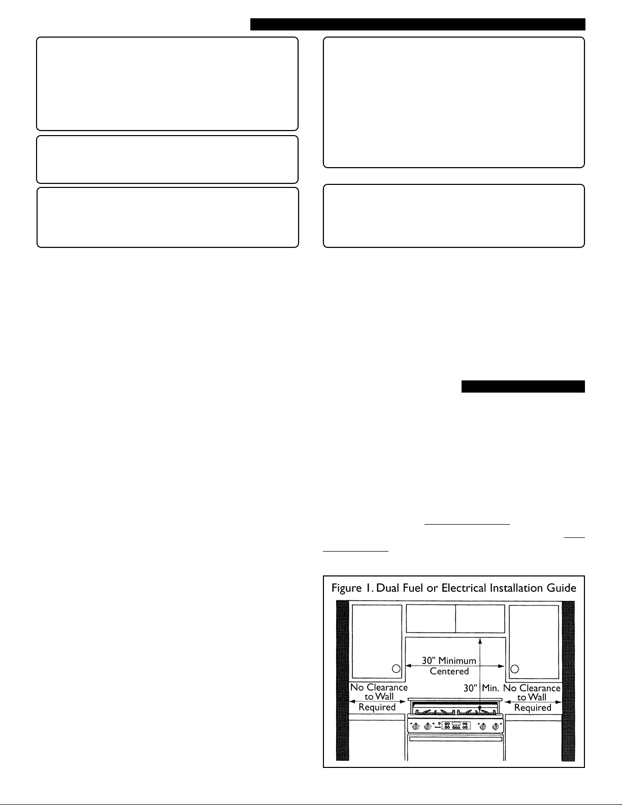
CABINET
This unit is designed for installation in a countertop near
adjacent walls and projecting surfaces constructed of
combustible materials. There must be a minimum clearance
of 30 inches between the top of the cooking surface and
the bottom of an unprotected wood or metal cabinet; or
24 inches when bottom of wood or metal cabinet is
protected by not less than 1/4" of flame retardant material
covered with not less than No. 28 MSG sheet metal, 0.015
inch stainless steel’ or 0.024 inch aluminum or copper. (See
Figure I). The minimum horizontal distance(s) from the
side and back edge of the unit to adjacent vertical
combustible walls are as follows: Zero clearance is permitted
on rear, right and left walls.
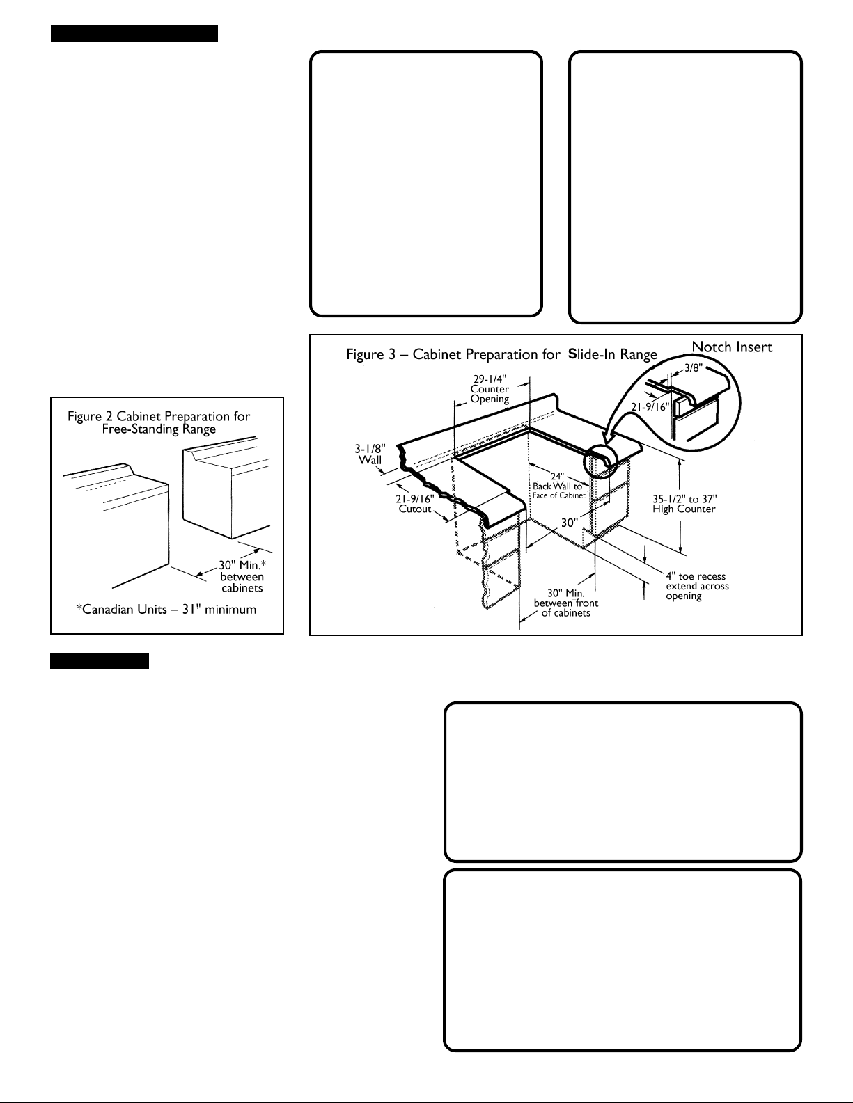
For the cabinets over the cooking surface and the adjacent
cabinets, the maximum cabinet depth from back wall is 13
inches.
Instructions were determined using Standard American base
cabinets measuring 36" high x 24" deep (see Figures 2 & 3).
When installed, the range must extend beyond the cabinet
doors/drawers. In an
layout a notch on the countertop on each side so the back
of the notches line up with the front of the cabinet doors.
(See NOTCH INSERT in Figure 3).
island or peninsula installation, first
2
Page 3
VENTILATION AND CABINET CONSIDERATIONS
Layout the remaining dimensions
positioned from the back of these
notches.
If nonstandard cabinets are used, care
should be taken to alter dimensions
accordingly.
NOTICE: Some cabinet flnishes
cannot survive the temperatures
allowed by U.L., particularly selfcleaning ovens; the cabinets may
discolor or stain. This is most
noticeable with laminated cabinets. If
your cabinet company does not
approve a temperature of 180° F., the
range should be installed such that the
oven front frame does NOT line up
BEHIND the pane of the front of the
cabinet doors.
CAUTION: To eliminate the
risk of burns or flre by reaching
over heated surface units, cabinet
storage space located above the
surface units should be avoided.
If cabinet storage is to be
provided, the risk can be reduced
by installing a range hood that
projects horizontally a minimum
of 5 inches beyond the bottom
of the cabinets.
■
ATTENTION: Pour élimıner le
risque de brûlures ou d’incendie
en atteindrant sur les unités de
la surface chauffés, I’espace
d’emmagasinage de l’armoire
localisée audessus des unités de
la surface doit être evitée. Si
l’emmagasinage de l’amoire est
d’être fourni, le risque peut être
réduit par l’installation d’un capot
de la cuisiniêre qui projette
horizontalement un minimum de
5 pouces au delâ du fond des
armoires.
GAS CONNECTION (MODELS RDF30, RDFS30 & RDSS30) ■
Be sure the unit being installed is compatible with
the type of gas available. The range is shipped from the
factory for use with natural gas.
Conversion for use with propane gas can be made by using
a kit, NLPK1T 6, P/N 35-00-688. Only a qualified technician
or installer should convert the range.
This kit includes instructions for adjusting valves and
pressure regulator and contains new burner jets.
The RDFS and RDSS models are equipped with an
intermittent/interrupted ignition device (ExtraLow®).
NATURAL GAS
The range is shipped from the factory for use with natural
gas only. The gas supply to the appliance regulator must be
a minimum of 6.0" water column. The maximum gas pressure
to the appliance regulator shall not exceed 14" W. C..
PROPANE GAS
CAUTION: When connecting unit to propane gas,
make certain the propane gas tank is equipped with
its own high pressure regulator in addition to the
pressure regulator supplied with the appliance. The
gas supply to the appliance regulator must be a
minimum of 11.0" water column. The maximum gas
pressure to the appliance regulator is not to exceed
14.0" water column from the propane gas tank.
ATTENTION: En branchant l’appareil au gaz de
propane, soyez certain que le réservoir de gaz du
propane est équipé avec son régulateur de haute
pression en addition du régulateur de pression fourni
avec cet appareil. La fourniture de gaz au régulateur
de l’appareil doit être un minimum de 11.0" colonne
d’eau. La pression de gaz maximale â cet appareil ne
doit pas excéder une colonne d’eau de 14.0 pouces
du régulateur du reservoir de gaz du propane.
3
Page 4

GAS CONNECTION (MODELS RDF30, RDFS30 AND RDSS301)
■
WARNING: Do not attempt any adjustment of the
pressure regulator except conversion to propane.
AVERTISSEMENT: Ne pas entreprener aucun
ajustement du régulateur de la pression excepte la
conversion â propane.
GAS PRESSURE (INCHES WATER COLUMN)
GAS SUPPLY MANIFOLD
Natural 6 to 14 5
Propane 11 to 14 10
IMPORTANT NOTES
(a) The appliance and its individual shut-off valve must be
disconnected from the gas supply piping system during
any pressure testing of that system at test pressures in
excess of 1/2 psig (3.5kPa).
(b) The appliance must be isolated from the gas supply
piping system by closing its individual manual shut-off
valve during any pressure testing of the gas supply piping
system at test pressures equal to or less than 1/2 psig
(3.5 kPa)
GAS CONNECTION
For gas units, a 1/2" N.P.T. wall gas supply can lie anywhere
within the shaded area. (See Figure 4.) This will provide
accessibility to the shut-off valve by removing the storage
drawer. Attach a 1/2" N.P.T. shut-off valve (not supplied) to
the wall stub-out. The other end of the valve should be
connected to a 3/8" flexible gas connector (not supplied).
The flexible connector shall be secured to the pressure
regulator located in the lower left rear area of the range
shown in Figure 5.
Note: Route flexible connector through grommet in rear
leg to avoid interference with drawer (See Figure 5.)
With the exception of flared fittings, always use pipe
dope or Teflon
careful not to apply excessive pressure when
tightening the fittıngs.
Turn on gas and check supply line connections for
leaks using a soap solution. Do not use a flame of
any sort to check for leaks.
®
tape on the pipe threads and be
For Massachusetts Installations:
1. Shut-off valve must be a “T” handle gas cock.
2. Flexible gas connector must not be longer than 36 inches.
3. Not approved for installation in a bedroom or a bathroom unless unit is direct vent.
4
Page 5

ELECTRICAL CONNECTION (ALL MODELS)
■
Ranges are dual rated for use on either 120/240 VAC or
120/208 VAC. See table for power ratings and circuit breaker
sizes based upon the supply voltage for each model:
MODEL REDF30, RDFS30, RDSS30
VOLTS HZ RATING CIRCUIT
A.C. KW BREAKER
120/240 60 3.8 20 AMPS
120/208 60 2.9 15 AMPS
MODEL REF30, RES30
VOLTS HZ RATING CIRCUIT
A.C. KW BREAKER
120/240 60 12.0 40 AMPS
120/208 60 9.0 40 AMPS
POWER SUPPLY CONNECTORS
This appliance may be connected to the power supply by
installing flexible conduit or a power cord set. The electrical
rating of the power cord set (not supplied) must be 120/
240 volt, 40 amperes minimum for models REF/RES and 20
amperes minimum for models RDF/RDFS/RDSS. The power
cord set shall be marked “For Use with Ranges.”
The power supply shall be connected to the range terminal
block compartment located in the lower left rear corner,
accessible by removing the storage drawer below the oven.
(See Figure 6.)
Remove the terminal box cover by removing the cover
screw. Install the proper connector in knockout(s) provided.
The electrical supply, including connectors or power cord,
can lie anywhere within the shaded area (See Figure 7.)
5
Page 6

ELECTRICAL CONNECTION (ALL MODELS)
■
Figure 8 – Conductor Securement
Figure 10a – 4-Wire Connection Ground Strap Figure 10b – 4-Wire Connection Neutral Wire
Figure 9 – Wire Connection
The terminal provided will accept leads with ring terminals
or stripped conductors. A flat washer and cup washer must
be used with stripped leads (See Figure 8).
ELECTRICAL CONNECTION
A 3- or 4-conductor supply may be connected to the
terminal block. A 4-conductor supply shall be used only
when the range is installed in a mobile home or where
local codes do not permit grounding through the neutral.
3 WIRE LEAD CONNECTION
1. Remove upper nuts only from the terminal block studs.
Do not remove nuts which secure range internal
wiring leads.
2. Secure the neutral, grounded wire of the supply circuit,
to the center stud of the terminal block with nut. (Figure
9).
3. Secure the L1 (black) and L2 (red) power leads to the
outside terminal block studs (brass colored) with nuts.
4. Tighten nuts securely.
4-WIRE LEAD CONNECTION
1. Remove upper nuts only from the terminal block studs.
Do not remove lower nuts which secure range
internal wiring leads.
2. Remove ground strap screw and bend the strap up.
(See Figure 10a.)
3. Secure the neutral wire to the center stud of the
terminal block with nut. Tape neutral wire to strap, as
shown in Figure 10b, to insure strap does not contact a
grounded surface.
4. Secure the L1 (black) and L2 (red) power leads to the
outside terminal studs (brass colored) with nuts.
5. Secure the bare copper ground lead to the range chassis
using the ground screw previously used for the ground
strap.
6. Tighten all connections securely.
6
Page 7

WARNING
ANTI-TIP WARNING
■
RANGE TIPPING HAZARD
• All ranges can tip and injury could result.
To prevent accidental tipping of the range,
attach it to the wall, floor or cabinet by
installing the Anti-TIp Device supplied.
• A risk of tip-over may exist if the appliance
is not installed in accordance with these
instructions.
• If the range is pulled away from the wall
for cleaning, service, or any other reason,
ensure that the Anti-Tip Device is properly
reengaged when the range is pushed back
against the wall. In the event of abnormal
usage (such as a person standing, sitting, or
leaning on an open door), failure to take
this precaution could result in tipping of the
range. Personal injury might result from
spilled hot liquids or from the range itself.
AVERTISSEMENT
!
◆
The range must be secured by the anti-tip bracket supplied.
Secure properly to prevent range from tipping, should
someone step or sit on oven door. To install, see step 2,
RANGE INSTALLATION on the following Page 8.
WARNING
• ALL RANGES CAN TIP
• INJURY TO PERSONS
COULD RESULT
• INSTALL ANTI-TIP
DEVICE PACKED WITH
RANGE
• SEE INSTALLATION
INSTRUCTIONS
DANGER DE RENVERSEMENT DE LA
CUISINIERE
• Toutes les cuisiniéres peuvent renverser et
la blessure peut résulter. Pour empêcher le
renversement accidental de la cuisiniére,
l‘attacher au mur, au plancher, ou â l’amoire
en installant L’Appareil Anti-Renversé
fourni.
• Un risque de renversement peut exister si
l’appareil n’est pas installé conformément
aux ces instructions.
• Si la cuisiniere est tirée loin du mur pour le
nettoyage, l’entretien, ou toute autre raison,
assurer que Les Appareils Anti-Renversé est
rengagés correctement quand la cuisiniére
est poussée contre le mur. Dans
l’événement d’usage abnormale (tel qu’une
personne qui est debout, est asslse, ou est
inclinée sur une porte cuverte), l'échec de
prendre cette précaution peut avoir pour
le résultat le renversement de la cuisiniére.
La blessure personnelle peut résulter des
liquids chauds répandus ou de la cuisiniére
elle-méme.
!
◆
AVERTISSEMENT
• TOUT LES CUISINIÉRES
PEUVENT RENVERSER
• LES BLESSURES AUX
PERSONNES PEUVENT
RESULTER
• INSTALLER L’APPAREIL
ANTI-RENVERSER
EMALLÉ AVEC LA
CUISINIÉRE
• VOIR LES
INSTRUCTIONS
D’INSTALLATION
7
Page 8

RANGE INSTALLATION
■
TO INSTALL THE RANGE:
1. Disconnect electrical power and turn off gas supply at
shut-off valve, if applicable.
2. Install anti-tip device as follows:
a) Adjust height of range and level by rotating the
adjustable leg supports, (see Figure 11) using 1/2"
wrench.
b) Attach anti-tip bracket to wall stud 1/4" maximum
above cross brace in back of oven. (See Figs. 12 &
13.) The anti-tip bracket shall allow the range back
brace to slide under the anti-tip bracket. (See Figure
13.)
c) If necessary add spacer between bracket and wall
to insure proper anti-tip bracket engagement.
3. Move range close to the cutout opening and insert cord
set plug into the receptacle or connect flexible conduit
. (All switches must be off.)
4. Secure the flexible gas connector to the shut-off valve.
(See Figure 5, Page 4.)
5. Slide range into position insuring the range back brace
slides under anti-tip bracket. Insure flexible gas
connections are not crimped.
6. Carefully tip range forward to insure that the anti-tip
bracket engages the range back brace and prevents tipover. (See Figure 14.)
7. Turn electrical power and gas supply on. Check range
for proper operation described in Care and Use Manual.
Thermador reserves the right to change specifications or design without notice. Some models are certified for use in Canada.
Thermador is not responsible for products which are transported from the United States for use in Canada. Check with your local
Canadian distributor or dealer. Thermador, 5551 McFadden Avenue, Huntington Beach, CA 92649.
For the most up to date critical installation dimensions by fax, use your fax handset and call 702/833-3600. Use code #8030.
5551 McFadden Avenue, Huntington Beach, CA 92649 • 800/735-4328
ECO14028 • 14-33-872H • © BSH Home Appliances Corp.1998• Litho U. S. A. 4/01
8
 Loading...