

Page 1

INSTALLATION
INSTRUCTIONS
For Built - in Microwave Ovens
Oven
Model
MBB
Built-In
Trim Kits
Models:
MET27B
MET30B
(Sold Separately)
Page 2
Please read this entire manual before proceeding
IMPORTANT:
INSTALLER: Please leave these Installation Instructions with this unit for the
OWNER: Please retain these instructions for future reference.
WARNING: Disconnect power at the breaker before installing.
Local codes vary. Installation, electrical connections, circuit breakers
and grounding must comply with all applicable codes. Save these instructions
for your local electrical inspector's use.
owner.
Table of Contents
Step 1: Unpacking ................................. 3
Step 2: Preparing the Cabinet ................ 4
Step 3: Preparing the Electric ................. 5
Step 4: Preparing the Trim Kit ................ 5
Step 5: Installing the Ducts .................... 6
Step 6: Completing the Installation......... 7
Page 2
Page 3
Step 1: Unpacking
A. Tools Needed:
• Tape Measure
• Drill with 1/16" bit
• Pliers
• # 2 Phillips Head Screwdriver
• Gloves
• Safety Goggles
Microwave Oven Model MBB
Remove and discard all packing
material.
Parts Included:
• Care & Use manual (1)
• Warranty Card (1)
• Plastic Turntable (1)
• Glass Tray (1)
B. Trim Kit Models MET27B & MET30B
Remove and discard all packing materials.
Parts Included:
• Trim Frame (1)
• Base Pan (1)
• Trim Bracket (2)
• Side Duct (1)
• Upper Exhaust Duct (1)
• Top Intake Duct (1)
• Rear Intake Duct (1)
• Installation Instructions (1)
• 10-foot Roll Tape (1)
• Screws #8 x
Point) (7)
• Screws #8 x
Point) (9)
• Grommet (1)
• Template (1)
• 7/16" Lag Bolts (2)
3/8" Type B (Blunt
3/8" Type A (Sharp
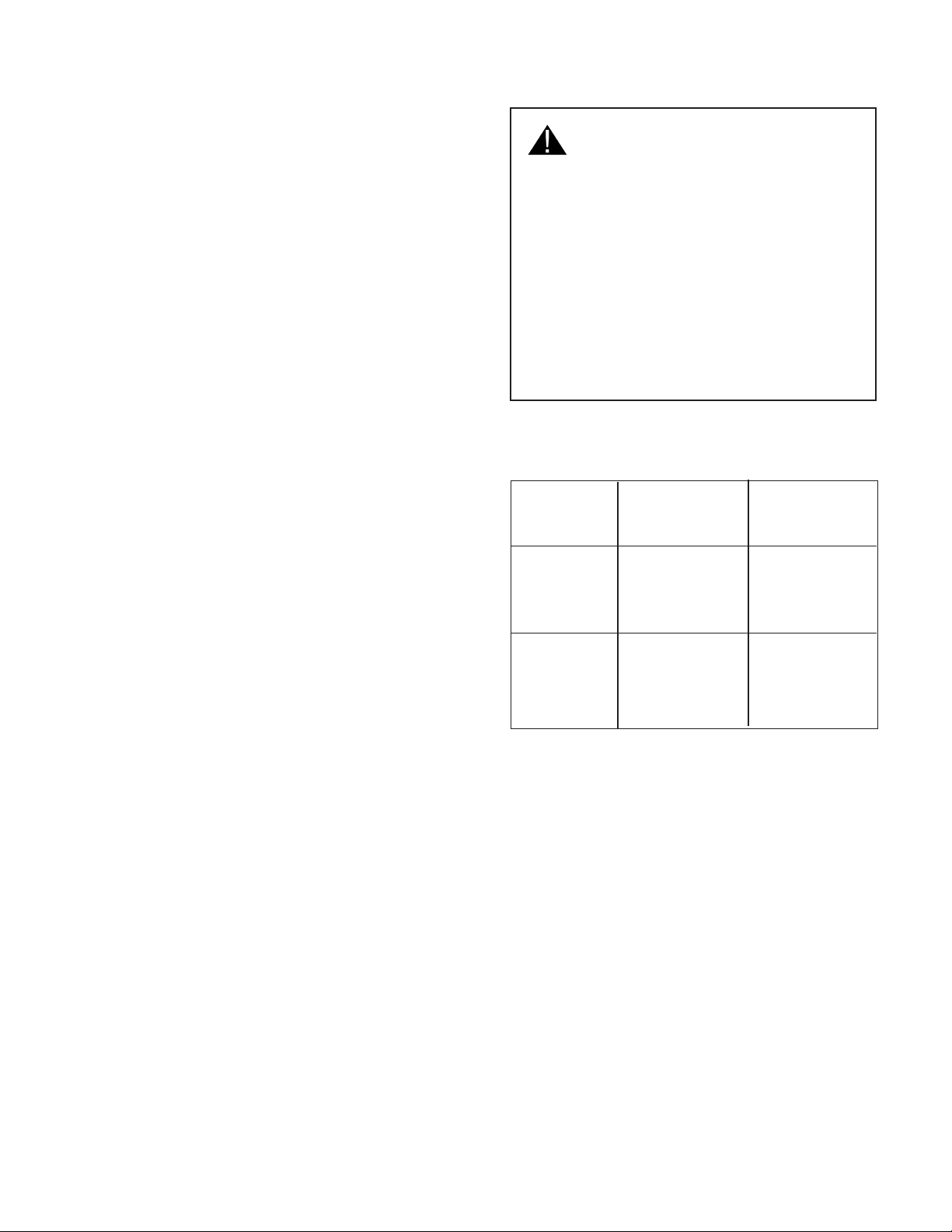
Caution:
• Trim kits are designed for use
• For safety, do not alter or
• Unit is heavy and requires at
Table 1 - Model Numbers
30" Cabinet
27" Cabinet
only with the Thermador
microwave oven models listed
(See Table 1).
modify any part of this kit or
oven.
least two people to lift or
move.
Trim Kits
MET30BB
MET30BW
MET30BS
MET27BB
MET27BW
MET27BS
Microwave
Ovens
MBBB
MBBW
MBBS
MBBB
MBBW
MBBS
Page 3
Page 4

4"
14"
4"
➛
➛
A
➝
➝
➝
➝
➛
➛
➛
➛
B
C
Step 2: Preparing the Cabinet
• The cabinet cutout dimensions are shown in
Figure 1.
• It is a good practice when the microwave oven is
installed at the end of a cabinet run, adjacent to a
perpendicular wall or cabinet door, to allow at least
1
/2"
(12.7 mm) space between the side of the trim
and wall or door.
Trim Kit Model
Dimension MET27B MET30B
Trim Height 17-1/4"17
Trim Width 26
Cutout Height (A) 17" ±
Cutout Width (B) 25-1/2" ±1/16"28-1/2" ±1 16"
Depth (C) 24" ±
-3
/4"29
1
/16" 17" ±1/16"
1
/16" 24" ±1/16"
-1
/4"
-3
/4"
Figure 1
• Your microwave oven can be installed into a
cabinet or wall by itself or above any of the
following Thermador wall ovens: C271, C301,
CM301, S301, SC301. Or,
Drawers WD27 and WD30 (see Figures 2a and
2b).
• Outlet can be located anywhere within the shaded
area as indicated in Figure 1.
Outlet should be
in the shaded area.
Thermador Warming
1"
(25.4 mm)
1-3/4"
(44.5 mm)
1" (25.4 mm) minimum
from cutout to wall.
Figure 2a
Figure 2b
Bottom of
microwave
shelf
Microwave
cutout
1-1/2"
}
(38 mm)
Warming
Drawer
cutout
Microwave
Cutout
Thermador
single wall
oven
cutout
}
}
Page 4
Page 5

Step 3: Preparing the Electric
The Thermador microwave oven is equipped with a grounded cord. The wall receptacle must be
installed and grounded in accordance with the national electrical code. It can be installed anywhere in
the shaded area in Figure 1 (previous page). Electrical connections and grounding must comply with all
applicable local codes.
The electrical requirements for a separate circuit serving only this microwave oven are: 120V, 60Hz,
15Amp.
WARNING: Improper grounding can result in risk of electric shock.
Step 4: Preparing the Trim Kit
(1) Attach the two vertical side trim brackets to the template as shown in Figure 3. Use two (2) #8 x
3
/8, Type B screws on each side.
(2) Mark the center line on bottom edge of the cutout.
(3) Hold template in front of cabinet cutout. Line up the bottom of the template with the bottom of the
cutout. Align the template notch with the centerline of the cutout.
(4) Mark the location of the three holes in the trim brackets on both sides. Set brackets and tem-
plate aside.
(5) Drill
(7) Remove template from trim brackets and discard. Set brackets and screws aside to be installed
Note: DO NOT attach trim brackets at this time. Continue to
1
/16" diameter starter holes.
later in the process.
Step 5: Installing the Ducts.
Trim Brackets
Screws #8
x
Template
3
/8"
Align notch in template
with center line
of cabinet cutout
Figure 3
Centerline
Page 5
Page 6

Step 5: Installing The Ducts
1. Remove and discard the protective plastic
film from the 4 ducts.
CAUTION
The ducts have sharp edges. Be careful when
handling.
2. Set microwave upside down in stable loca-
tion.
3. Use pliers to remove and discard all four (4)
black plastic feet from bottom of microwave.
4. Attach base pan to bottom of microwave at
leg holes. Fasten with two (2) 7/16" lag bolts.
Install one bolt through front right leg hole
and one through back left hole. Return microwave to right-side-up position.
2. Loosen the outer case screw near the vent
on left side of the microwave.
3. Position side duct on left side of oven. Slide duct
under loosened outer case duct screw and tighten.
4. Position upper exhaust duct on top left side (hinge
side) of oven. The left side will overlap the side
duct. Fasten upper exhaust duct and side duct
to microwave using two (2) #8 x 3/8" Type B
screws.
5. Wrap grommet around electrical cord.
6. Thread grommet and electrical cord in the
receiving hole provided in the rear intake duct.
7. Attach rear intake duct to the rear of the oven.
Fasten with one (1) #8 x 3/8" Type B screw.
6. Position top intake duct on top side of oven. Slide
the back edges under the rear intake duct. Fasten
top intake duct and rear intake duct to microwave
using four (4) #8 x 3/8" Type B screws.
Side
Duct
Microwave
Oven
Upper
Exhaust
Duct
7. Use tape provided to cover all duct seams. Verify
Grommet
that all seams are tightly sealed.
Top
Intake
Duct
Rear
Intake
Duct
Outer Case Screw
Base Pan
(center hole)
Figure 4
Page 6
Page 7

Step 6: Completing the Installation
Caution: The microwave oven is heavy. Always use at least two people to lift the unit.
1. Lift oven into position and rest right rear corner in cabinet cutout.
2. Reach past microwave on left side to insert
electrical cord into outlet.
3. Slide oven the rest of the way into the cabinet. Position microwave in cabinet so that
base pan center hole aligns with cabinet
centerline. When properly installed, the front
end of pan will be flush with the front edge
of the shelf.
4. Open the microwave door to access three
holes on the base pan below the microwave.
Drill 1/16" holes through the three (3) base
pan holes into the cabinet cutout bottom.
Fasten base pan to shelf with three 3 #8 x
3/8 Type A screws.
11. Install both vertical trim brackets on the cabinet using three (3) #8 x 3/8 Type A screws
on each side. The flanges on the ends of
the brackets should be inside the cabinet.
12. Snap frame trim into the trim brackets
(Figure 6). The four (4) ball studs on the
back of the frame snap into the four (4) spring
clips on the trim brackets. Tip: Place
screwdriver behind spring clip to support
bracket.
13. Install the plastic turntable. Place in center
of oven bottom with base in hole. Turn
turntable clockwise until it drops into place.
Place glass tray on top of turntable.
Figure 5
Frame Trim
Figure 6
14. Test the operation of the microwave. See
the Care & Use manual for operating instructions.
Page 7
Page 8

Thermador reserves the right to change specifications or design without notice. Some models are
certified for use in Canada. Thermador is not responsible for products which are transported from
the United States for use in Canada. Check with your local Canadian distributor or dealer. Thermador,
5551 McFadden Avenue, Huntington Beach, CA 92649.
For the most up-to-date critical installation dimensions by fax, use your fax handset and phone
702/833-3600. Use code #8030.
BSH Home Appliances Corporation
5551 McFadden Avenue, Huntington Beach, CA 92649 • 800/735-4328
RO 2011M • 9000012356A • © 2004 BSH Home Appliances Corp. • Litho Date 06/04
 Loading...