

Theben theRonda S360-100 DE GR, theRonda S360-100 DE WH, theRonda S360-100 AP WH, theRonda S360-100 AP GR Operating Instructions Manual
EN
Presence detector
theRonda S360-100 DE WH
2080560
theRonda S360-100 DE GR
2080561
theRonda S360-100 AP WH
2080550
theRonda S360-100 AP GR
2080551
1. Product characteristics
Passive infrared presence detector for ceiling installation
•
Circular detection area 360°, up to Ø 9 m (64 m2)
•
Automatic presence- and brightness-dependent control
•
for lighting
Mixed light measurement suitable for uorescent lamps
•
(FL/PL/ESL), halogen/incandescent lamps and LEDs
Channel A light: relay, 230 V
•
Operation as fully automatic device
•
Brightness switching value congurable, teach-in
•
function
Pulse function for staircase light timer switch
•
Time delay congurable
•
Detection sensitivity congurable
•
Ready for immediate use due to factory presetting
•
Test mode for checking function and detection area
•
Installation in false ceilings with springs, type DE
•
Ceiling installation surface mounted, type AP
•
User remote control "theSenda S" (optional)
•
Management remote control "SendoPro" (optional)
•
Service remote control "theSendaP" (optional)
•
2. Safety
307233
1103107601
3. Proper use
The presence detector is intended for indoor installation. The
presence detector is exclusively intended for the use as contractually agreed between the manufacturer and the user. Any
other use is considered to be unacceptable. The manufacturer
does not accept liability for any resulting damages.
4. Operation
The presence detector is primarily used in passageways such
as corridors, stairs, toilets, basements and garages as well
as in homes for easy and energy-efcient control of lighting.
The switch contact "light" switches lighting on with presence
and insufcient brightness, and off with absence or sufcient
brightness.
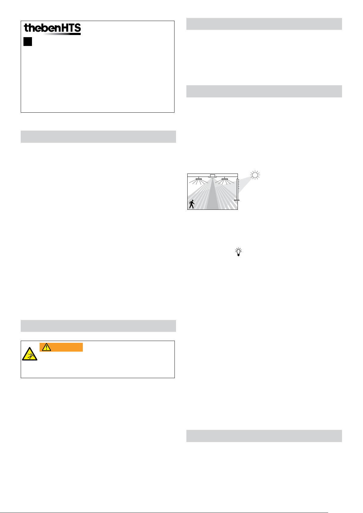
Function description
Mixed light measurement
Presence detection
Articial light
Incident daylight
Channel A light
Switching response is controlled by presence and brightness.
The switch contact for Channel A light closes during darkness
and when someone is present. It opens with a delay when
there is brightness or once the room is vacated after the set
time delay.
Time delay
The time delay enables delayed switching off of lighting after
the room is vacated. The time delay is adjustable in a range of
10s to 60min.
WARNING
Danger of death through electric shock or fire!
Installation should only be carried out by a
qualied electrician!
Work on electrical systems may only be carried out by
•
qualied electricians or by instructed persons under the
guidance and supervision of a qualied electrician in
accordance with the technical regulations applying to
electricity!
Comply with the country-specic safety regulations for
•
work on electrical systems! Ensure absence of voltage in
the cable before installation!
The device is maintenance-free. If the device is opened
•
or penetrated with any object, the guarantee lapses.
Fully automatic device
Lighting control of the presence detector operates fully automatically for increased comfort. The lighting switches on and
off automatically as a "fully automatic device".
Pulse function
Time delay can be set to pulse for controlling existing staircase light timer switches. To do so, the light output produces
a pulse of 0.5s in duration every 10 seconds if people are
present or it is dark.
5. Detection area
The circular detection area of theRonda S presence detector
covers an average detection area. Note that seated persons
are detected in different sized areas. The recommended installation height is 2 m – 4 m. As installation height increases,
the sensitivity of the presence detector decreases. The extent
and distance between the active and passive zones of the
1
presence detector also increases. The detection range is reduced as the temperature increases.
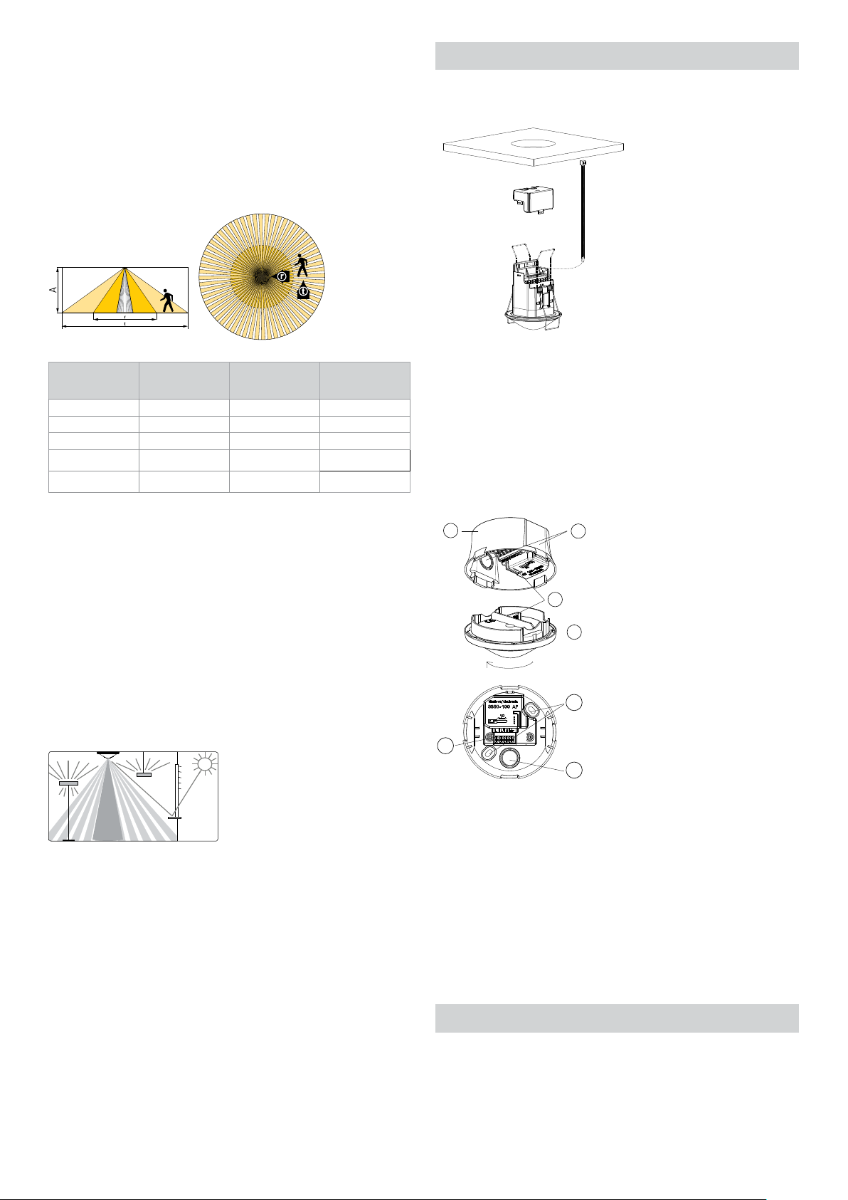
6. Installation
Seated people
The presence detector reacts very sensitively to the slightest
movements. The details refer to smallest movements at table
height (approx. 0.80 m). The detection sensitivity is reduced
from an installation height of > 3 m. More pronounced movements are required for clear detection.
Installation
height (A)
2.0m Ø 7.0m (38m2) Ø 2.5m (5m2) Ø 2.5m (5m2)
2.5m Ø 7.0m (38m
3.0m Ø 8.0m (50m
3.5m Ø 8.0m (50m
4.0m Ø 9.0m (64m2) Ø 4.0m (13m2)
Across (t) Frontal (r) Seated (s)
2
) Ø 3.0m (7m2) Ø 3.0m (7m2)
2
) Ø 4.0m (13m2) Ø 4.0m (13m2)
2
) Ø 4.0m (13m2)
–
–
All gures are guidance values.
Brightness measurement
Ceiling installation
Installation in false ceilings for ceiling thicknesses of 0.5mm
to 3cm. The diameter of the ceiling cutout must be between
62mm and 70mm. The cable strain relief is implemented
using a cable tie (width: 3.5 – 4.8mm).
The detector requires a clear line of sight to people. The installation height must not be below 1.7m and not higher than
4m.
Ceiling installation - surface mounted
c
b
The presence detector measures articial light and daylight
that is reected below the detector (opening angle approx.
120º). The installation location is the reference point for the
lighting level. Direct light inuences the light measurement.
Avoid placing oor lamps or suspended lighting directly
below the detector.
If the brightness measurement is deactivated, the channel A
light only switches depending on the presence (brightness
switching value set to "measurement off" via the remote
control).
Suitable lamps
The presence detector is designed for the operation of uorescent lamps, compact uorescent lamps, halogen/incande-
scent lamps and LEDs. The maximum number of switchable
lights is restricted due to the high inrush current levels of
the EBs and LED drivers. The use of an external contactor
helps with large loads. All switched loads must be properly
suppressed.
e
a
20°
open
c
d
b
Turn the sensor unit (a) by about 20° counterclockwise, up
to the snap-in point.
Remove the sensor unit.
Break out the required cable passages (b).
Mount the power supply unit (c) on the ceiling using the
provided fastening holes (c).
Wiring in accordance with the label on the plug-in terminal,
cable cross section 0.25 – 2.5mm2 (d)
Afx the sensor unit (a) paying attention to the plug-in
connection (e).
7. Switching
The presence detectors can be operated as a Master in individual switching. With parallel switching of the light outputs
(L'), it must be ensured that all detectors connected in parallel
are connected to the same phase.
2
 Loading...