

Theben thePassa P360-221 DALI UP WH, thePassa P360-221 DALI UP GR User Manual
Presence detector
A
EN
thePassa P360-221 DALI UP WH
2010340
thePassa P360-221 DALI UP GR
2010341
307421
19.10.2018
3. Proper use
The presence detector is used in passageways, stairca-
•
ses, garages, basements and warehouses for controlling
the lighting and HVAC.
The presence detector is intended for indoor installation.
•
4. Installation
1. General information
Passive infrared presence detector for ceiling installation
•
2 operating modes for lighting channel, switchable:
•
– 1 DALI broadcast lighting channel (factory setting) or
– 2 DALI addressable lighting channels
2 separate detection zones
•
Rectangular detection area (max. 30 m x 5 m/150 m2)
•
Switch or constant light control mode
•
with standby function
Mixed light measurement suitable for uorescent lamps
•
(FL/PL/ESL), halogen/incandescent lamps and LEDs
Adaptable 2-channel light measurement
•
Fully or semi-automatic operation, switchable
•
Reduction of time delay when present briey (short-term
•
presence)
1 presence channel for external DALI relay, e.g. for HVAC
•
control
Accessories: SendoPro 868-A management remote
•
control (optional) (SendoPro for short); theSenda S user
remote control (optional) (theSenda S for short); theSenda P service remote control (optional) (theSenda P
for short); theSenda B app remote control (optional) and
the corresponding "theSenda Plug" app (iOS/Android)
(theSenda B/app for short)
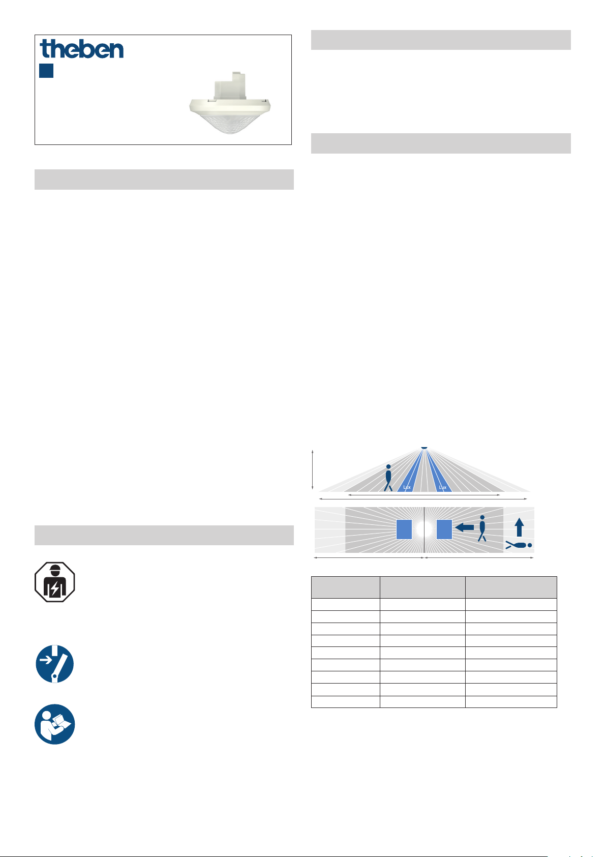
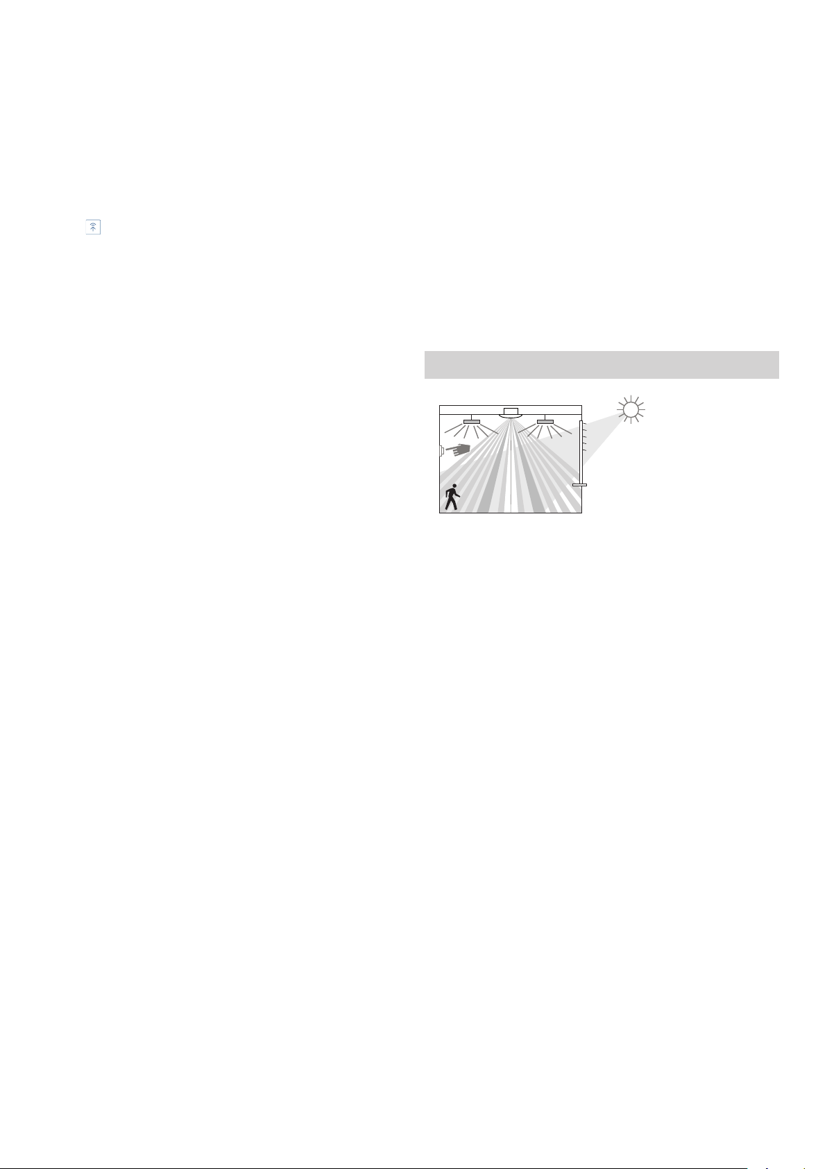
Detection area
L The rectangular detection area enables the entire corridor
to be covered.
L The detection area is divided into two zones. These can
be activated or deactivated individually by remote control
(only with 1 DALI broadcast lighting channel).
L Recommended installation height: 2.0 m – 6.0 m.
The sensitivity of the presence detector decreases when
the installation height is increased. From a installation
height of 3.5 m, the detection areas of several detectors in
the edge zones should overlap.
L The detection range is reduced as the temperature
increases.
L The detection area is divided into different areas based on
the walking direction (frontal/across).
Detection areas: zone 1 and zone 2 (factory setting)
r
t
r
t
2. Safety
Assembly and installation should only be carried
out by a qualied electrician, somebody who has
completed appropriate professional training and
has the knowledge and experience necessary to be
able to recognise and avoid the potential dangers
posed by electricity.
Before assembly/dismounting, disconnect the
power supply and ensure that the parts are no
longer live.
Read the entire manual and follow the instructions.
Prior to commissioning and using the product, read
the operating instructions.
Installation height
(A)
2.0 m 16 x 3.5 m (56 m2) 16 x 3.5 m (56 m2)
2.5 m 18 x 4 m (72 m2) 22 x 4 m (88 m2)
3.0 m 20 x 4.5 m (90 m2) 30 x 4.5 m (135 m2)
3.5 m 20 x 5 m (100 m2) 30 x 5 m (150 m2)
4.0 m 20 x 5 m (100 m2) 30 x 5 m (150 m2)
4.5 m 20 x 5 m (100 m2) 30 x 5 m (150 m2)
5.0 m 20 x 5 m (100 m2) 30 x 5 m (150 m2)
5.5 m 20 x 5 m (100 m2) 30 x 5 m (150 m2)
6.0 m 20 x 5 m (100 m2) 30 x 5 m (150 m2)
All gures are guidance values.
Zone 1 Zone 2
Walking persons
frontal (r)
Walking persons
across (t)
1
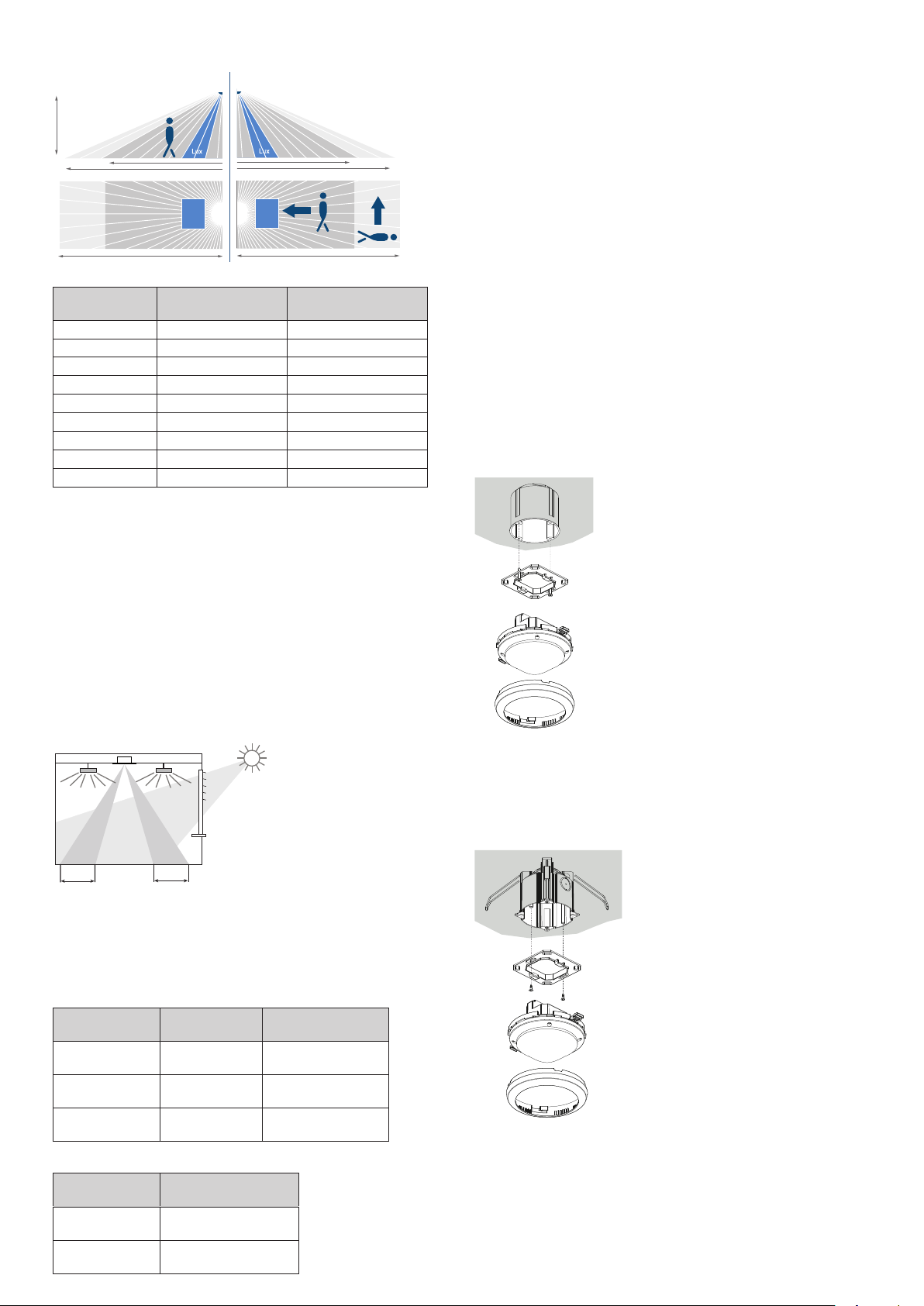
Detection areas: zone 1 or zone 2
r
t
r
t
r
t
r
t
A
L The alignment of both zone 1/zone 2 brightness measu-
rements must be taken into account!
L Direct light in uences the light measurement. Avoid pla-
cing oor lamps or suspended lighting directly under the
r
t
detector.
Constant light control
r
t
The detector must be positioned in such a way that it only
detects arti cial light that it controls itself. Arti cial light
controlled by other detectors (or manually switched working
lights) will affect the brightness measurement of the detector.
Installation height
(A)
2.0 m 8 x 3.5 m (28 m
2.5 m 9 x 4 m (36 m
3.0 m 10 x 4.5 m (45 m
3.5 m 10 x 5 m (50 m
4.0 m 10 x 5 m (50 m
4.5 m 10 x 5 m (50 m
5.0 m 10 x 5 m (50 m
5.5 m 10 x 5 m (50 m
6.0 m 10 x 5 m (50 m
Walking persons
frontal (r)
Walking persons
across (t)
2
) 8 x 3.5 m (28 m2)
2
) 11 x 4 m (44 m2)
2
) 15 x 4.5 m (68 m2)
2
) 15 x 5 m (75 m2)
2
) 15 x 5 m (75 m2)
2
) 15 x 5 m (75 m2)
2
) 15 x 5 m (75 m2)
2
) 15 x 5 m (75 m2)
2
) 15 x 5 m (75 m2)
All gures are guidance values.
Brightness measurement
The presence detector measures arti cial light and daylight
by means of two directed light measurements. Light measurement Z1 measures the brightness in zone 1. In zone 2, light
measurement Z2 measures the brightness. The alignment of
both brightness measurements has to be taken into account
during installation. The installation location is the reference
point for the lighting level. The brightness measurement can
be adapted to the conditions in a room with the room correction factor.
Switching mode
If the brightness measurement is deactivated, the lighting
only switches based on the presence detection function
(brightness setpoint value is set to «Measurement off» via the
remote control).
Flush-mounted installation
with standard ush-mounting box, size 1
Z1 Z2
2 m
2 m
Each light measurement zone maps a rectangle of about 2 x
4 m on the oor. Depending on the operating mode and the
selected detection zone, the light measurements are assigned
as follows:
1-channel (broadcast):
Selection of detection zone
Only zone 1 Channel C1 - light Zone 1
Only zone 2 Channel C1 - light Zone 2
Zone 1 + zone 2 Channel C1 - light
Lighting channel Light measuring zone
Ø from zone 1 +
zone 2
2-channel (addressable):
Lighting channel Light measuring zone
Channel C1 - light Zone 1
Channel C2 - light Zone 2
Ceiling installation
with ceiling installation box 73A (9070917), for installation
diameter 72 mm (Ø 73 mm)
2
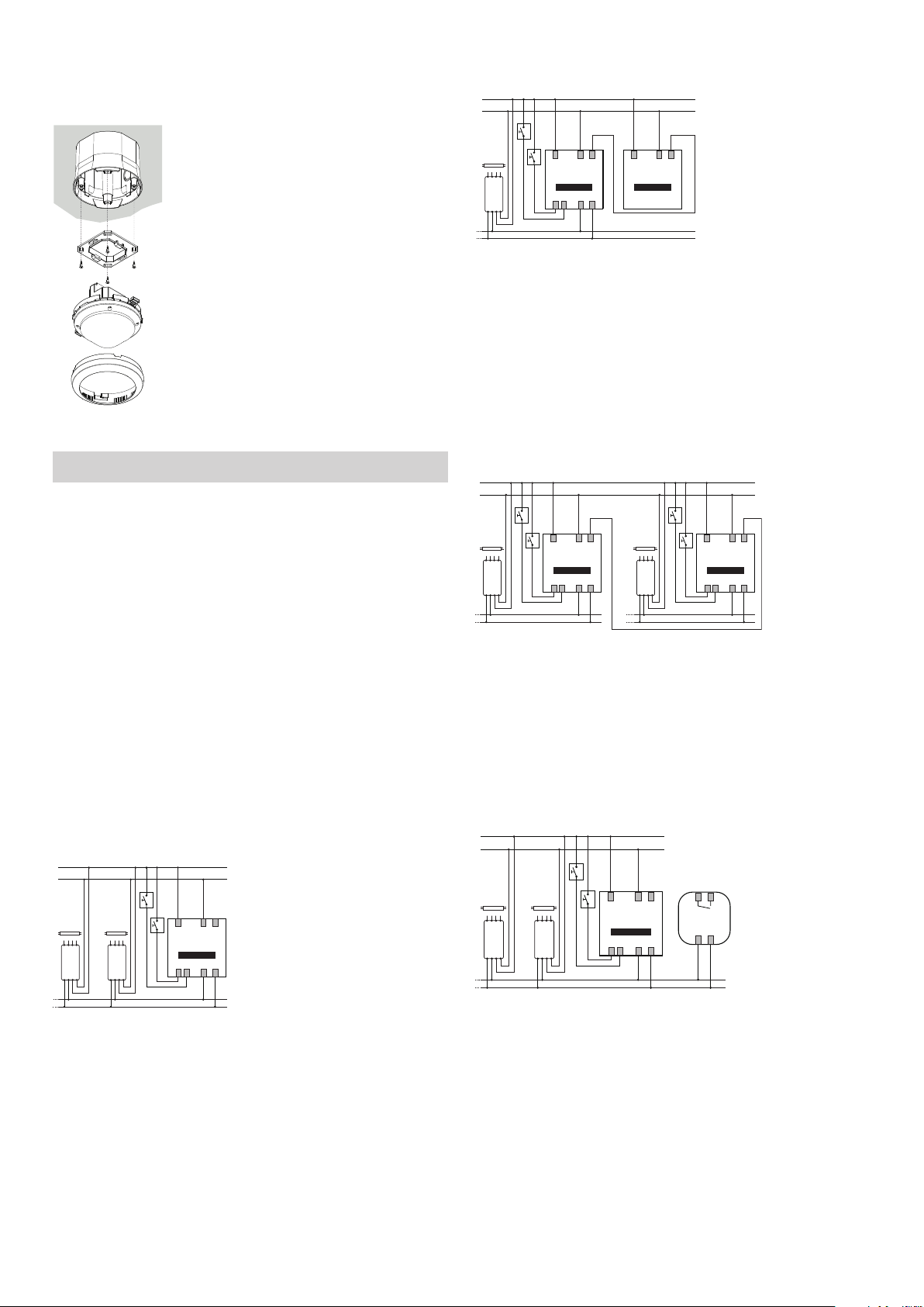
Surface-mounted installation
N
L
N
L
**
N
L
with back box 110A (9070912, 7070913)
The other detectors (slaves) merely provide presence
•
information (e.g. thePassa P360 Slave UP).
L
N
*
5. Connection
Use the same external conductor for all detectors and
!
buttons.
L Several buttons can be connected to one control input.
L Illuminated buttons can only be used with a neutral con-
ductor connection.
L Up to 50 DALI operating devices can be connected to
each master device. Distribute the DALI operating devices
evenly over the 3 external conductors.
L In the addressable operating mode, lighting channels C1
and C2 can be assigned to the required button inputs S1
and S2 via the remote control.
Individual switching
As master, the presence detector detects presence and
•
brightness and controls lighting.
PNL
Master
EVG
DALI
*Only for the "addressable" operating mode
DA+ DA–S1 S2
PNL
Slave
Master/master parallel switching
Several masters can be used. Every master controls
•
its lighting groups according to its own brightness
measurement.
Time delays and brightness setpoint values are set indi-
•
vidually on each master.
Presence is detected collectively by all the detectors.
•
Switch up to 10 detectors in parallel.
•
PNL
Master
EVG
DALI DALI
*Only for the "addressable" operating mode
DA+ DA–S1 S2
EVG
Master
PNL
DA+ DA–S1 S2
Integrating an external DALI relay
No more than 1 external DALI relay can be connected on
•
one single DALI line (IEC 62386-208).
The detector automatically detects the DALI relay.
•
Switch-on delay and time delay can be set using the
•
remote control.
*
P*NL
Master
EVG
*Only for the "addressable" operating mode
EVG
DALI
DA+ DA–S1 S2
Master/slave parallel switching
If the detection area of a single presence detector is
•
insuf cient (spacious rooms), a maximum of 10 detec-
tors can be connected in parallel by connecting the P
terminals.
Presence is detected collectively by all the detectors.
•
The master measures the brightness, processes the
•
button information and controls the lighting.
PNL
Master
EVG
*Only for the "addressable" operating mode
EVG
DALI
DA+ DA–S1 S2
DALI RMr
3
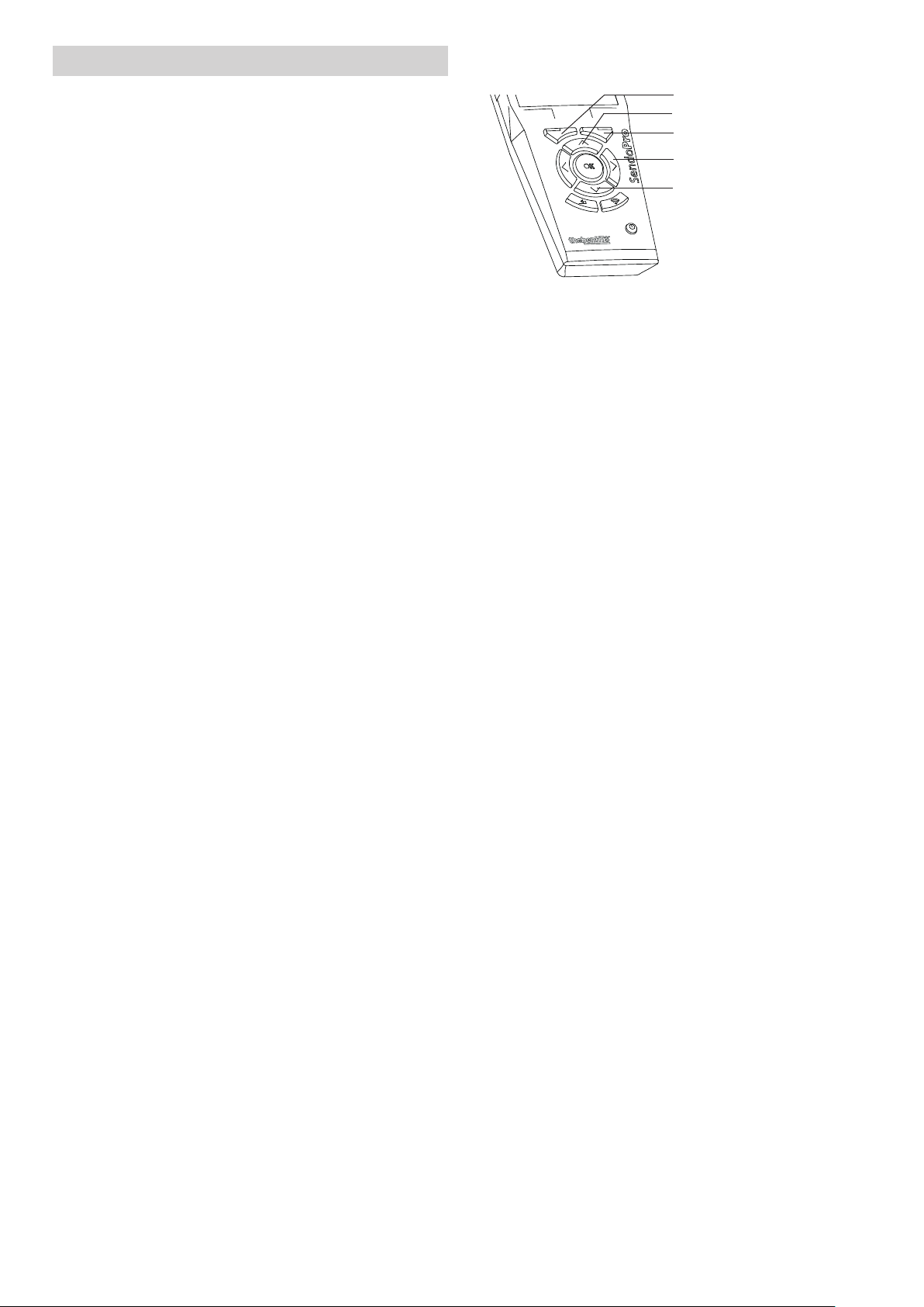
6. Start-up
Initial operation of thePassa P360-111 DALI
(broadcast) → factory setting
Configuring the lighting groups with SendoPro
Left function button
Up button
Right function button
Right button
L After the start-up phase (30 s), the detector is ready for
operation.
Initial operation of thePassa P360-221 DALI
(addressable), uncongured system
The operating mode can be switched from broadcast to
addressable with the SendoPro remote control or the theSenda B/app:
Select the <thePassa P360-111 DALI> parameter as the
detector type.
Open the DALI conguration ("Control commands" menu in
the SendoPro).
Send the <Change over to addressable operating mode>
parameter to the detector.
After the changeover, select <thePassa P360-221> as the
detector type for further parameterization.
After the rst changeover to the addressable operating mode
(thePassa P360-221 DALI), the detector restarts, identies all
connected DALI lights, assigns short addresses and manages
them in a list.
▻ Depending on the system size, the LED on the detector
ashes (5 x ON briey every 3 s) for up to 3 min.
If no DALI EBs are connected to the detector or a DALI line is
interrupted
▻ the LED ashes (LED is switched on and ashes 2 x OFF
briey every 3 s).
If the system is functioning, the detector switches to conguration mode and waits for the conguration of the lighting
groups.
▻ The LED ashes (2 x ON briey every 3 s).
As long as the conguration has not been carried out, the
system is in the following operating state:
Detector is in broadcast mode.
•
Function is in switching mode (only presence detection,
•
no light measurement).
All lights are controlled with 100% switch-on dimming
•
value.
The operating mode is fully automatic device.
•
All connected buttons are active. Switching on and off as
•
well as dimming are possible.
Time delay: 10 min.
•
Configuring the lighting groups with
SendoPro
•
theSenda B/app
•
Buttons or theSenda S
•
Down button
Select "thePassa P360-221 DALI" as the type in the
SendoPro.
Select "Menu" (right function button) then "Control com-
mands" (left function button).
Open "DALI conguration" with "Open" (right function
button).
For the DALI conguration, there are 3 options available:
y "Group assignment (unaddress.)": only DALI EBs without a
group address are processed.
y "Group assignment (all)": all connected DALI EBs are con-
gured. NOTE: All existing group assignments with group
number 1 or 2 are deleted.
y "Change group assignment": the next existing EB is
searched for and selected.
Use the Up or Down button to select the required group
assignment and press "Send" (right function button) to
start the conguration.
L The remote control must be directed to the detector! The
LED is switched off.
▻ A DALI light starts to pulse (random order).
Select the required C1 or C2 channel with the button and
assign it to the DALI EB by pressing "Send" (right function
button).
▻ As conrmation, the light dims to 20%.
▻ The next DALI light starts to pulse. One after the other,
the lighting groups are assigned to all the lights.
For group assignment (unaddress.) or (all): if all DALI EBs
•
are assigned to a lighting group, the detector terminates
the conguration process and restarts (startup phase of
30 s). The detector then switches to the normal opera-
ting mode and the conguration is completed.
L If necessary, the conguration process can be ended by
pressing "End" (left function button).
▻ In this case, the system is not ready for operation.
If "Change group assignment" has been selected, use the
•
right ">" button to switch to the next DALI EB without
changing the lighting group.
When all required changes have been made, end the con-
guration process by pressing "End" (left function button).
Configuring the lighting groups with the theSenda B/app
Connect the theSenda B with the corresponding "theSenda
Plug" app.
Place the theSenda B under the detector (direct the remote
control towards the detector).
Select "thePassa P360-221 DALI" as the type in the "the-
Senda Plug" app.
In the "DALI conguration" menu, select the required group
assignment.
4
For the DALI conguration, there are 3 options available:
y "Group assignment (unaddress.)": only DALI EBs without a
group address are processed.
y "Group assignment (all)": all connected DALI EBs are con-
gured. NOTE: All existing group assignments with group
number 1 or 2 are deleted.
y "Change group assignment": the next existing EB is
searched for and selected.
▻ After selecting the required group assignment, the
detector is in the programming mode.
▻ A DALI light starts to pulse (random order).
Use to assign the required C1 or C2 channel to the DALI
EB.
For further steps, see "Conguring the lighting groups with
SendoPro".
Configuring the lighting groups using buttons
Set the <Conguration button/RC> parameter to "Enabled".
All connected buttons can be used for the conguration.
Press any button 5 times briey (< 0.4 s) and press and
hold once (> 15 s).
▻ The LED is switched off.
▻ A DALI light starts to pulse (random order).
▻ The lighting group is assigned by pressing the approp-
riate button:
y 1 x short button press = channel C1
y 2 x short button press = channel C2
▻ As conrmation, the light dims to 20% (3 s after the
last button press).
▻ The next DALI light starts to pulse. One after the other,
the lighting groups are assigned to all the lights.
If all DALI EBs are assigned to a lighting group, the
•
detector terminates the conguration process and
restarts (startup phase of 30 s).
▻ The detector switches to the normal operating mode
and the conguration is completed.
L If required, the conguration process can be ended by
pressing and holding any button for longer than 15 s. The
detector restarts.
▻ In this case, the system is not ready for operation.
L Instead of using the button, the conguration can also
be carried out with the ON/OFF buttons on the theSenda
B/S.
Checking the configuration
The assignment of the lighting groups can be checked by
switching the individual lighting groups on or off using buttons, the SendoPro remote control or the theSenda B/app (for
SendoPro/theSenda B (app), select the "Control commands"
menu).
L Changing the lighting group for DALI EBs: use the Sendo-
Pro or the theSenda B/app to change the DALI conguration via the "Change group assignment" command.
L With the button: the whole DALI conguration must be
re-executed.
L A video on conguring the lighting groups can be found at
https://www.youtube.com/user/TheThebenAG
Switch-on response (congured system)
If voltage is applied, the presence detector goes through two
phases which are indicated by the LED:
1. Start-up phase (30 s)
The red LED ashes in one-second intervals; the lighting
•
is switched on with the switch on dimming value.
The detector does not react to button commands or to
•
the theSenda B/S.
If absent, the lighting is switched off after 30 s.
•
2. Operation
The red LED is off. The constant light control or switching
•
mode are started.
▻ The detector is ready for operation.
7. Functions
Mixed light measurement
Presence detection
Articial light
Button for manual lighting control
Incident daylight
Lighting channel C1 (broadcast)
Lighting channel C1, C2 (addressable)
The lighting is controlled by presence and brightness. In case
of little daylight and presence, the articial light is switched
on via the DALI interface and regulated to a constant brightness level.
In case of sufcient daylight or absence, the lighting is switched off via the DALI interface.
Constant light control
Z1
It compensates for daylight uctuations by controlling
•
the lighting.
The total brightness is kept constant at the required
•
brightness level.
The lighting is switched on with the switch on dimming
•
value and regulated to the set brightness setpoint value.
Depending on the "school" or "ofce" conguration type,
•
the presence detector responds as follows after manual
dimming using the buttons:
"School" conguration type (in school and conference
rooms):
y Manual dimming stops the constant light control.
y When someone is present, the lighting remains at the
dimmed value (no brightness inuence).
y Switching off and on again leads to control mode.
Z2
5
"Ofce" conguration type (in single and open-plan
•
ofces):
y After manual dimming, the constant light control remains
temporarily active with the current brightness value as the
new brightness setpoint value.
y The new brightness setpoint value only applies while some-
one is present.
y After the lighting time delay, the set brightness setpoint
value is restored.
Switching mode
The switching response is controlled by presence and
•
brightness.
The lighting channel switches on in darkness and when
•
someone is present. The lighting switches off if there is
sufcient brightness or during periods of absence after
the set lighting time delay.
The light is switched on with the switch-on dimming
•
value.
The button can be used to change the intensity of the
•
articial light when someone is present. If the lighting is
switched on with the button, it remains switched on for
at least 30 min. If people have left the room (before), the
lighting switches off after the set time delay.
Standby (orientation light)
After the lighting time delay, the lighting is set to the
•
standby dimming value (1–25% of the lamp output).
The standby time can be set between 0 s and 60 min or
•
permanently.
If the room brightness is above the brightness setpoint
•
value, the lighting switches off. If the room brightness is
below the brightness setpoint value, the lighting switches to the standby brightness. If someone reenters the
room, the detector switches back automatically (fully
automatic device) or after pressing the button (semiautomatic device) to the set brightness setpoint value.
Lighting time delay
The minimum time delay (10 s – 60 min) is adjustable
•
and can increase to max. 30 min or decrease back to the
set minimum time.
With settings ≤ 2 min or ≥ 30 min, the time delay
•
remains unchanged at the set value. If someone briey
enters and leaves an unoccupied room within 30 s,
the lighting switches off early after 2 min (short-term
presence).
Button control
The lighting can be switched or dimmed manually via a
•
button.
A short button press switches the light on or off; a long
•
button press dims the light (brighter or darker).
If the lighting is switched off manually, it remains
•
switched off as long as people are present. The lighting
switches on again after the time delay has elapsed.
Fully or semi-automatic device
Fully automatic device: the lighting is switched on and
•
off automatically.
Semi-automatic device: the lighting must be switched on
•
manually. It is switched off automatically.
Staircase light function
If the staircase light function is activated, the detector is
•
used as a staircase automatic device. It is not possible to
switch the lighting off manually.
If the staircase light function is deactivated, the lighting
•
can be switched on and off manually.
eco and eco plus
Settings for ideal switching response and maximum energy
savings.
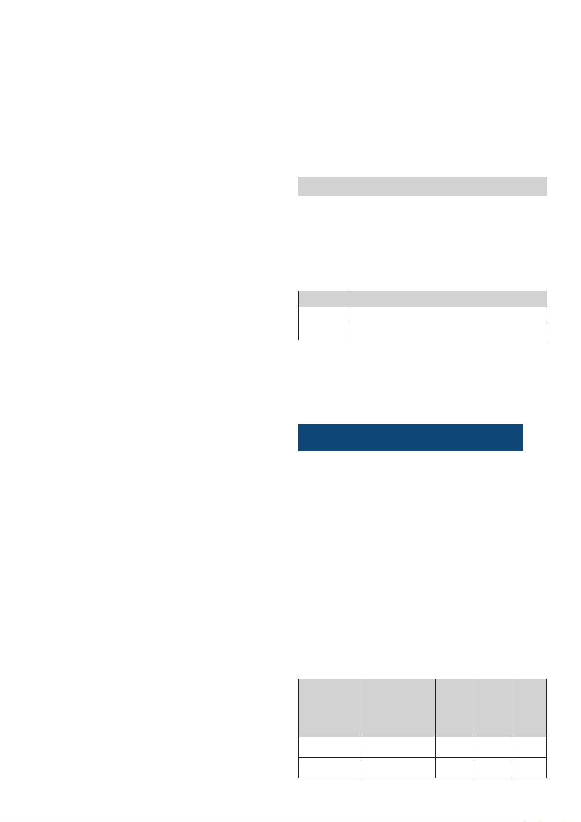
8. Settings
The thePassa P360-221 DALI presence detector features two
different operating modes:
Broadcast (factory setting)
•
Addressable
•
Both operating modes can be selected with the SendoPro or
the theSenda B/app.
Parameter Selection
Type thePassa P360-111 DALI (broadcast)
thePassa P360-221 DALI (addressable)
The presence detectors are supplied with basic settings
•
ready for operation.
With SendoPro and the theSenda B/app, parameters can
•
be checked, adjusted and optimised during start-up.
With the theSenda P, parameters can only be adjusted.
•
Broadcast <thePassa P360-111 DALI>
Teach-in via button
Press the button for > 15 s
▻ The currently measured brightness value is adopted as
the brightness setpoint value.
L The teach-in function via the button can be disabled using
the SendoPro or the theSenda B/app remote controls
when the "Conguration button/RC" parameter is set to
"disabled".
Parameters via remote control
The following parameters can be checked or changed via
the remote control for support during start-up as well as
servicing:
Parameter Description Can be
Detection zone
Function C1
Selection: Z1 / Z2 /
Z1+Z2
Selection:
switching/control
checked
by SendoPro/theSenda B
(app)
Can be
changed
by SendoPro/
theSenda
B (app)
x x
x x
Can be
changed
by theSenda P
6
 Loading...