

Theben MIX 2, RMG 4 U, RME 4 U Series Manual

MIX 2 series RMG 4 U / RME 4 U actuators
RMG 4 U 4930223
RME 4 U 4930228
MIX 2 series actuators
RMG 4 U / RME 4 U
Updated: Apr-15 (Subject to changes) Page 1 of 50

MIX 2 series RMG 4 U / RME 4 U actuators
Contents
1 Functional characteristics ................................................................................................ 4
2 MIX and MIX2 devices ..................................................................................................... 5
3 Operation ........................................................................................................................... 6
4 Technical data ................................................................................................................... 7
5 The application programme "MIX2 V1.8" ..................................................................... 8
5.1 Selection in the product database ........................................................................... 8
5.2 Communication objects ........................................................................................... 9
5.2.1 Channel-related objects: ......................................................................................... 9
5.2.2 Common objects: .................................................................................................. 12
5.2.3 Description of objects ........................................................................................... 13
5.3 Parameter ................................................................................................................ 20
5.3.1 Parameter pages .................................................................................................... 20
5.3.2 Parameter description ........................................................................................... 21
5.3.2.1 The "General" parameter page ..................................................................... 21
5.3.2.2 The "RMG 4 U basic module" parameter page ............................................ 23
5.3.2.3 The "RMG 4 U channel Cx: Configuration options" parameter page .......... 24
5.3.2.4 The "Contact characteristics" parameter page ............................................ 26
5.3.2.5 The "On/Off delay" parameter page ............................................................. 27
5.3.2.6 The "Pulse function.." parameter page ......................................................... 27
5.3.2.7 The "Staircase light with forewarning function .." parameter page ............. 28
5.3.2.8 The "Flashing.." parameter page .................................................................. 29
5.3.2.9 The "Threshold" parameter page .................................................................. 30
5.3.2.10 The "Block function" parameter page ....................................................... 32
5.3.2.11 The "Scenes" parameter page ................................................................... 33
5.3.2.12 The "Feedback" parameter page .............................................................. 36
5.3.2.13 The "Hour counter and service" parameter page ..................................... 37
5.3.2.14 The "Link" parameter page ....................................................................... 39
6 Typical applications ......................................................................................................... 40
6.1 2x switching with push button interface .............................................................. 40
6.1.1 Devices: ................................................................................................................ 40
6.1.2 Overview .............................................................................................................. 40
6.1.3 Objects and links .................................................................................................. 40
6.1.4 Important parameter settings ................................................................................ 41
6.2 Switching light with service counter and display ................................................ 42
6.2.1 Devices ................................................................................................................. 42
6.2.2 Overview .............................................................................................................. 42
6.2.3 Objects and links .................................................................................................. 43
6.2.4 Important parameter settings ................................................................................ 44
6.3 Simple warning function with flashing light ........................................................ 45
6.3.1 Devices: ................................................................................................................ 45
Updated: Apr-15 (Subject to changes) Page 2 of 50

MIX 2 series RMG 4 U / RME 4 U actuators
6.3.2 Overview .............................................................................................................. 45
6.3.3 Objects and links .................................................................................................. 45
6.3.4 Important parameter settings ................................................................................ 46
7 Appendix .......................................................................................................................... 47
7.1 The scenes ................................................................................................................ 47
7.1.1 Principle ............................................................................................................... 47
7.1.2 Call up or save scenes: ......................................................................................... 48
7.1.3 Teach in scenes without telegrams (MIX2 devices ONLY) ................................ 50
7.2 Conversion of percentages to hexadecimal and decimal values ......................... 50
Updated: Apr-15 (Subject to changes) Page 3 of 50

MIX 2 series RMG 4 U / RME 4 U actuators
1 Functional characteristics
• MIX2 4-way switch actuator.
• MIX2 basic module.
• Can be upgraded to a maximum of 12 channels.
• Up to 2 MIX or MIX2 extension modules can be connected to a basic module.
• Device and KNX bus module can be swapped independently of each other.
• Removable KNX bus module enables devices to be changed without reprogramming.
• Manual set-up and use of switch actuators is also possible without KNX bus module.
• LED switching status indicator for each channel.
• Manual operation on device (even without bus voltage).
• Adjustable features: e.g. switching, delayed switching, pulse function.
• Links, type of contact (NC contact/NO contact) and participation in central commands such
as permanent On, permanent Off, central switching, and save/call up scene.
• Switch functions: e.g. On/Off, pulse, On/Off delay, staircase light with forewarning.
• Logical links: e.g. block, AND, release, OR.
• Activation of the channel function via 1-bit telegram or 8-bit threshold.
Updated: Apr-15 (Subject to changes) Page 4 of 50
MIX 2 series RMG 4 U / RME 4 U actuators
MIX2 basic
493…
RMG 4 I, RMG 4 U,
BMG 6 T
MIX2
493…
RME 4 I, RME 4 U,
6 T.
MIX basic
491…
BMG 6, DMG 2 S, HMG 4,
RMG 4 C-load, SMG 2 S
MIX extensions
491…
BME 6, DME 2 S, HME 4,
RME 4 C-load, SME 2 S
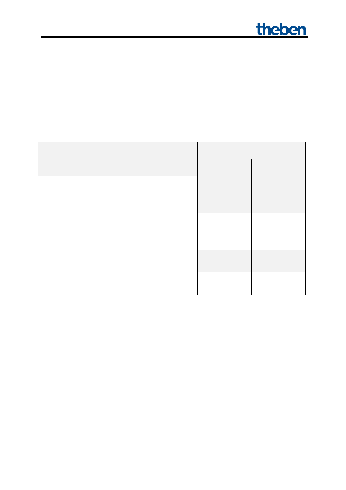
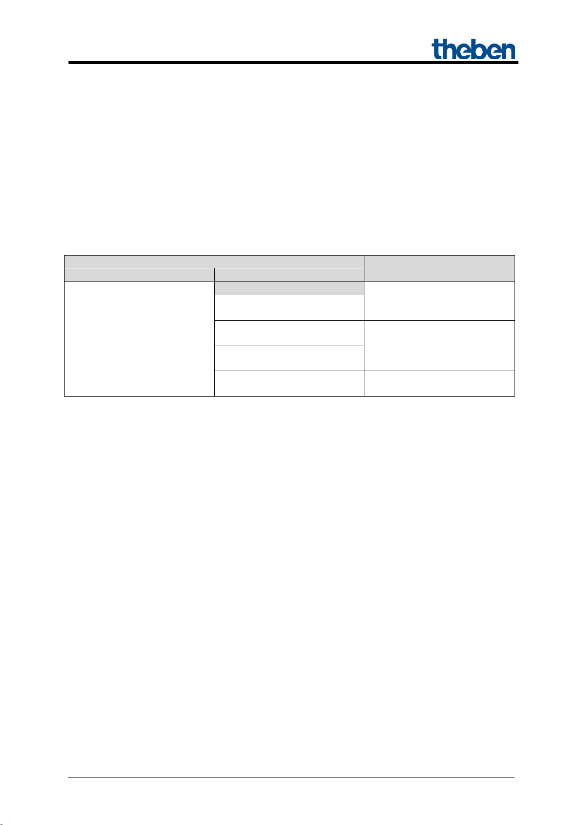
2 MIX and MIX2 devices
The MIX2 series consists of the basic modules RMG 4 I, RMG 4 U, RMG 8 S, RMG 8 T, DMG 2 T,
JMG 4 T, JMG 4 T 24V, HMG 6 T, BMG 6 T + extensions RME 4 I,
RME 4 U, RME 8 S, RME 8 T, DME 2 T, JME 4 T, JME 4 T 24V, HMG 6 T, BME 6 T (as of
03/2015).
Any MiX and MIX2 extension modules can be connected to a MIX2 basic module.
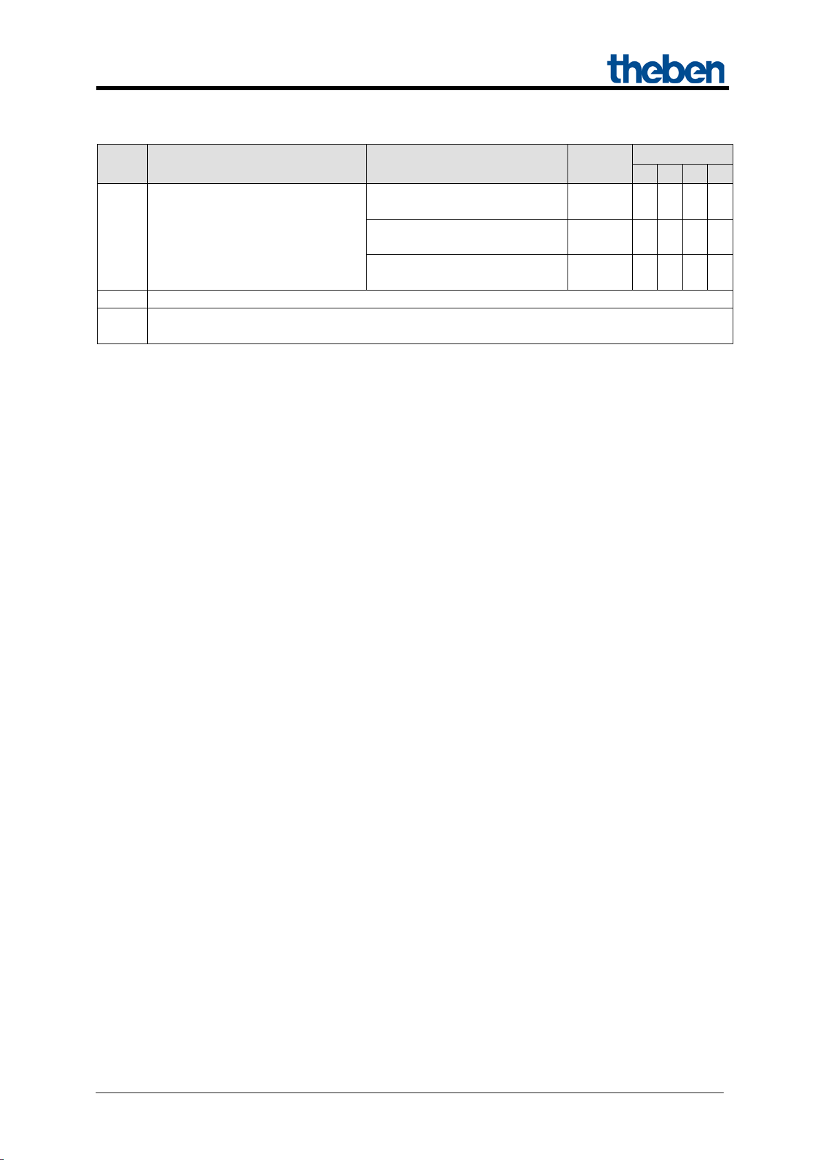
Table 1
Device type
modules
extensions
modules
* Adjusted parameter display and object numbering.
Ord.
No.
Designation
RMG 8 S, RMG 8 T,
DMG 2 T, JMG 4 T,
HMG 6 T, JMG 4 T 24V,
RME 8 S, RME 8 T,
DME 2 T, JME 4 T,
HME 6 T, JME 4 T 24V, BME
JMG 4 S, RMG 4 S,
JME 4 S, RME 4 S,
Can be used with basic module..
in the MIX series
- -
no Yes
- -
yes Yes*
in the MIX2
series
Updated: Apr-15 (Subject to changes) Page 5 of 50

MIX 2 series RMG 4 U / RME 4 U actuators
3 Operation
Each channel can be switched on and off independently of all parameters using the buttons on the
device. A status LED displays the current switching status.
All bus telegrams are ignored with manual operation switched on (manual button) and the channels are
exclusively to be operated via the buttons.
Mains voltage is required for the functioning of the buttons and LEDs, bus voltage or bus module are
not required.
Updated: Apr-15 (Subject to changes) Page 6 of 50

MIX 2 series RMG 4 U / RME 4 U actuators
KNX operating voltage
Bus voltage, ≤ 4 mA
Operating voltage
110 – 240 V AC
Frequency
50 – 60 Hz
Standby output
0.3 W
Type of installation
DIN-rail
Width
4 TE
Connection type
KNX bus terminal
Solid: 0.5 mm² (Ø 0.8) to 4 mm² | strand with
crimp terminal: 0.5 mm² to 2.5 mm²
Number of channels
4
Contact gap
< 3 mm
Voltage output
240 V AC
Switch output
Floating
Switching of different phases
Possible
Type of contact
16 A, 3 A NO contact
Resistive load
3680 W
Incandescent and halogen lamp load
2000 W
Fluorescent lamp load (KVG)
parallel-corrected
Fluorescent lamp load (KVG) not
corrected
Fluorescent lamp load (EB)
1200 W
Energy-saving lamps
300 W
LED lamps
< 2 W = 55 W or > 2 W < 8 W = 180 W
Suitable for SELV
Yes, if all channels switch SELV
Ambient temperature
-5 °C … +45 °C
Protection rating
IP 20
Protection class
II in accordance with EN 60 730-1
4 Technical data
Max. cable cross-section
1300 W (140 μF)
2000 VA
Updated: Apr-15 (Subject to changes) Page 7 of 50

MIX 2 series RMG 4 U / RME 4 U actuators
Manufacturer
Theben AG
Product family
Output
Product type
RMG 4 U
Program name
MIX2 V1.8
Number of communication objects:
254
Number of group addresses:
254
Number of associations:
255
5 The application programme
"MIX2 V1.8"
5.1 Selection in the product database
The ETS database can be found on our downloads page: www.theben.de/en/downloads_en.
Table 2
Updated: Apr-15 (Subject to changes) Page 8 of 50

MIX 2 series RMG 4 U / RME 4 U actuators
Type
Flags
C R W
T
1 bit
1,001
1 byte
5,001
1 byte
5,010
Threshold EIS 5
(DPT9.xxx)
2 byte
9.xxx
2 byte
7,001
1 bit
1,001
1 bit
1,001
1 bit
1,001
1 bit
1,003
1 byte
18,001
Block scenes = 1
1 bit
1,003
Enable scenes = 1
1 bit
1,001
2 byte
7,001
2 byte
7,001
1 bit
1,001
C R W
T
5.2 Communication objects
The objects are divided into channel-related and common objects
5.2.1 Channel-related objects:
Table 3:
No. Object name Function
Switch object
Threshold as percent
0 RMG 4 U channel C1
1 RMG 4 U channel C1
2 RMG 4 U channel C1 Block
3 RMG 4 U channel C1 Call up/save scenes
4 RMG 4 U channel C1
Threshold 0..255
Threshold 0..65535
Logic input in AND gate
Logic input in OR gate
Logic input in XOR gate
DPT
5 RMG 4 U channel C1 Feedback On/Off
Time to next service
6 RMG 4 U channel C1
Operating hours feedback
7 RMG 4 U channel C1 Service required
Updated: Apr-15 (Subject to changes) Page 9 of 50
MIX 2 series RMG 4 U / RME 4 U actuators
Type
Flags
C R W
T
2 bit
2,001
1 bit
1,001
1 bit
1,001
9
Not used
10..
198
Continuation:
No. Object name Function
Switching with priority
8 RMG 4 U channel C1
Channels C2 .. C4 and extension modules: See next table.
Reset service
Reset operating hours
DPT
Updated: Apr-15 (Subject to changes) Page 10 of 50
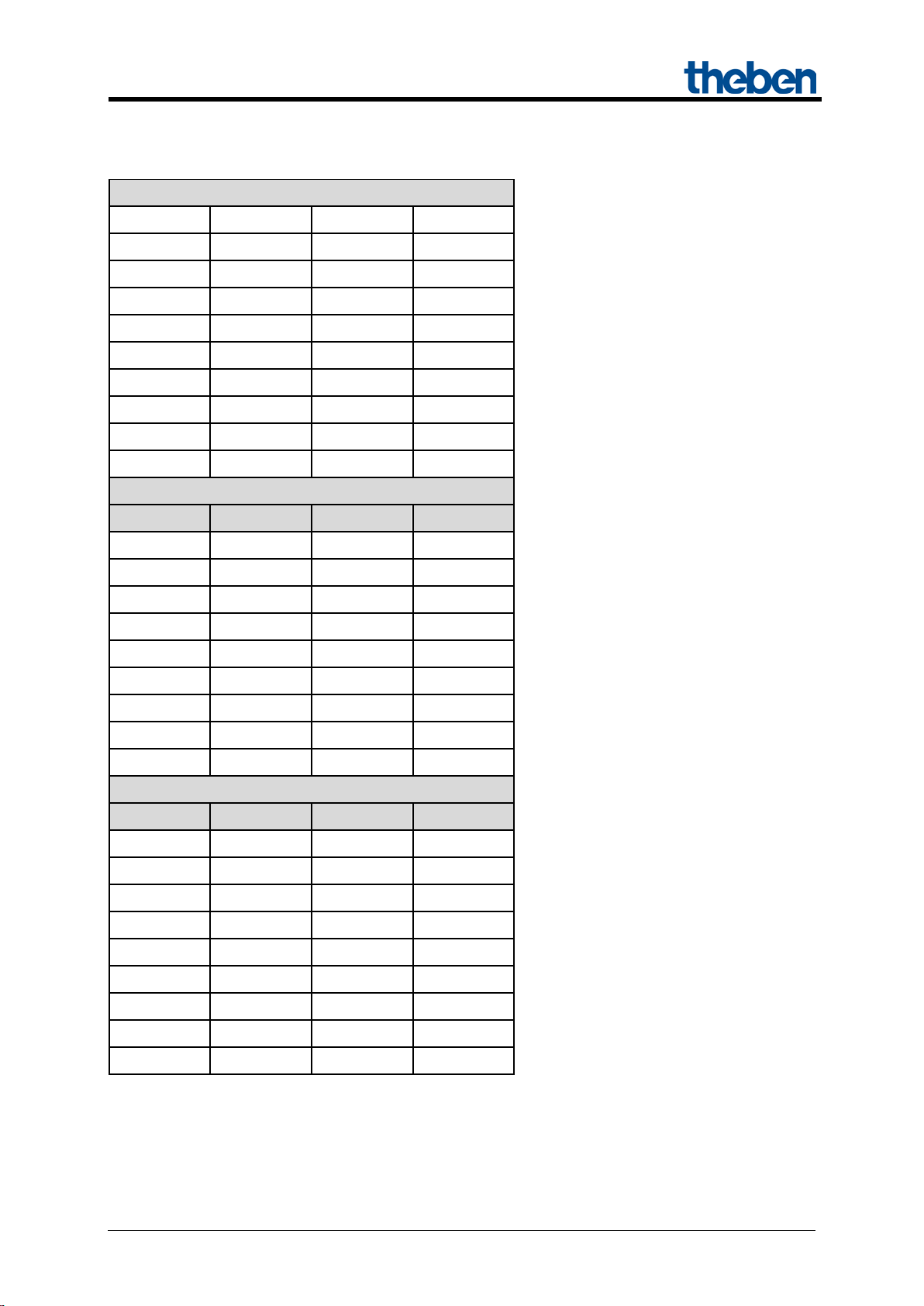
MIX 2 series RMG 4 U / RME 4 U actuators
BASIC MODULE: RMG 4 U
C2 C3
10 20
11 21
12 22
13 23
4
14
24
34
15 25
16 26
17 27
18 28
C1
C2
C3
C4
80
90
100
110
81
91
101
111
82
92
102
112
83
93
103
113
84
94
104
114
85
95
105
115
86
96
106
116
87
97
107
117
88
98
108
118
2nd EXTENSION: RME 4 U
C1
C2
C3
C4
160
170
180
190
161
171
181
191
162
172
182
192
163
173
183
193
164
174
184
194
165
175
185
195
166
176
186
196
167
177
187
197
168
178
188
198
Table 4: Overview of channel-related objects
C1
0
1
2
3
5
6
7
8
C4
30
31
32
33
35
36
37
38
1st EXTENSION: RME 4 U
Updated: Apr-15 (Subject to changes) Page 11 of 50
MIX 2 series RMG 4 U / RME 4 U actuators
Type
Flags
C R W T 78
RMG 4 U
158
EM1 RME 4 U
238
EM2 RME 4 U
RMG/E4x/8x,DMG/E2x,
SME2S
1 bit
1,001
RMG/E4x/8x,DMG/E2x,
SME2S
1 bit
1,001
RMG/E4x/8x,DMG/E2x,
SME2S
1 bit
1,001
RMG4x/8x,DMG/E2x,
JMG/E4x,SME2S
1 byte
18,001
1 bit
1,001
1 bit
1,001
1 bit
1,001
1 bit
1,008
1 bit
1,002
1 bit
1,002
14 byte
16,001
14 byte
16,001
14 byte
16,001
14 byte
16,001
C R W
T
5.2.2 Common objects:
These objects are partly used by the basic module and the two extension modules.
Table 5:
No. Object name Function
Manual
240 Central continuous ON
241 Central continuous OFF
242 Central switching
243 Call up/save central scenes
244 Central safety 1 For JME 4 S
245 Central safety 2 For JME 4 S
246 Central safety 3 For JME 4 S
247 Central up/down For JME 4 S
248 Central safety rain For JMG 4 T
DPT
1 bit
1,001
249 Central safety frost For JMG 4 T
250 Version of bus coupling unit transmit
251 Version of basic module transmit
252 Version of 1st extension module transmit
253 Version of 2nd extension module transmit
Updated: Apr-15 (Subject to changes) Page 12 of 50
MIX 2 series RMG 4 U / RME 4 U actuators
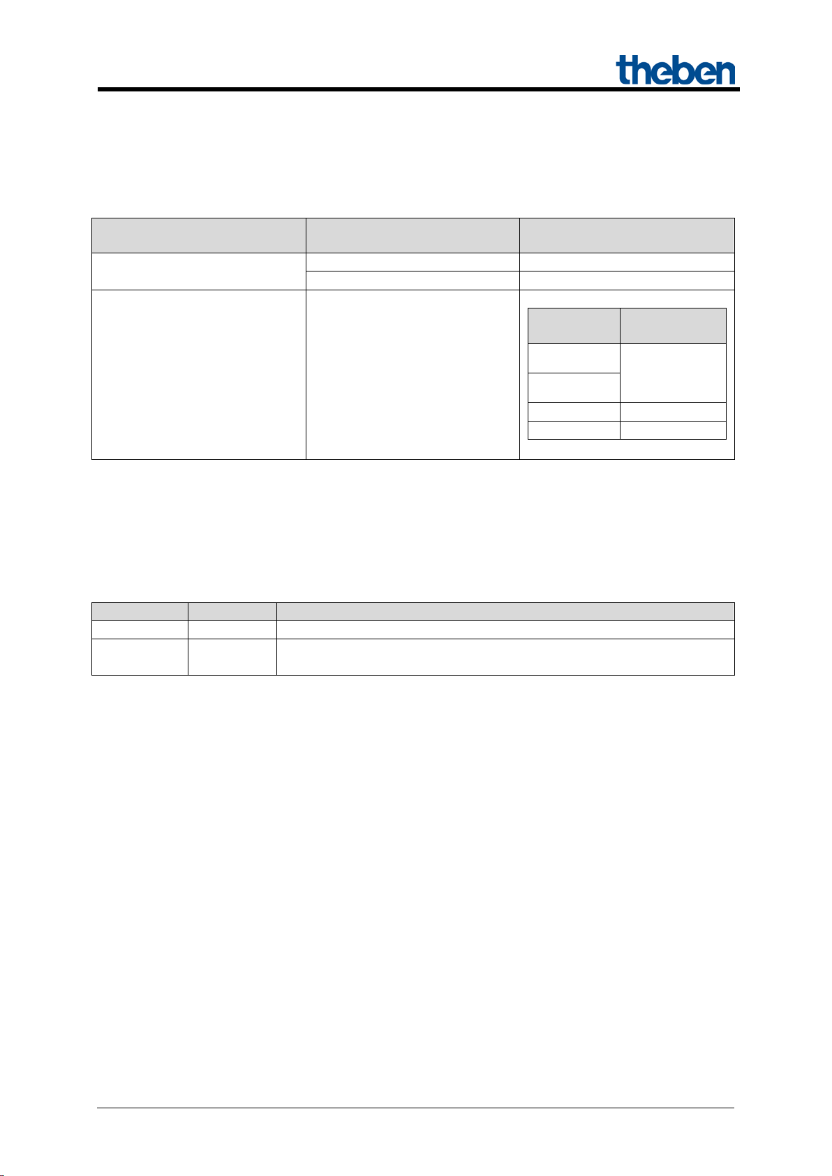
Parameter
Activation of channel function
via
Activation of function via
Type of threshold object
Switch object
1-bit telegram
Object type: Percent (DPT
5.001)
Object type: Counter value
0..255 (DPT 5.010)
Object type: Counter value
0..65535 (DPT 7.001)
Object type: EIS5 e.g. CO2,
brightness (DPT 9.xxx)
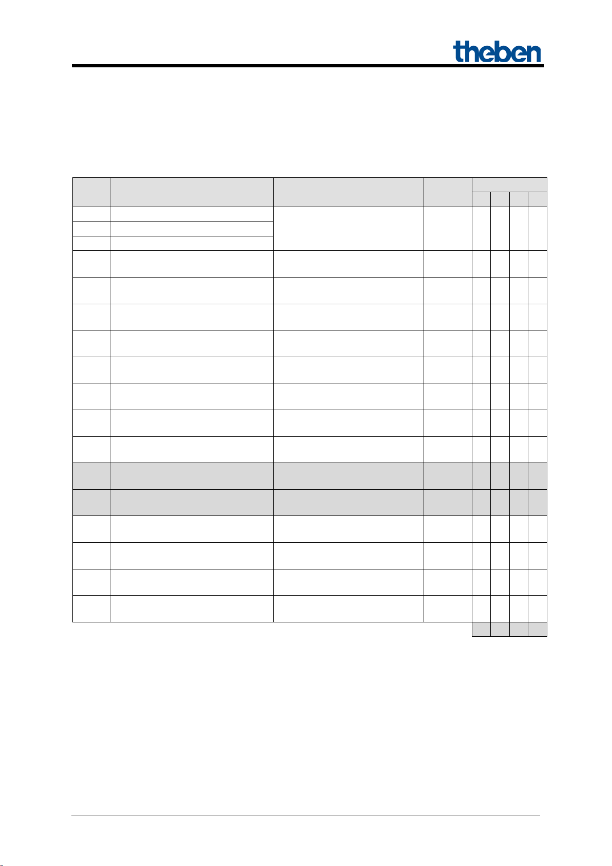
5.2.3 Description of objects
• Object 0 "Switch object, threshold as percent, threshold 0..255, threshold EIS 5
(DPT 9.xxx), threshold 0..65535 "
This object activates the set channel function (see parameter: Channel function).
The set channel function can either be activated via 1-bit telegram or by exceeding a threshold (8- or
16-bit telegram).
Table 6:
Exceeding percentage value
Exceeding the threshold
• Object 1 "Logic input in AND gate, in OR gate, in XOR gate"
Only availab le if Link is activated (Configuration options parameter page).
Forms a logical link together with object 0 to activate the channel function.
• Object 2 "Block"
Locks the channel function.
Responses to setting and cancelling the block can be configured if the block function has been
activated (Configuration options pa rameter page).
Any value in given numerical
range
2 byte floating-point number
Updated: Apr-15 (Subject to changes) Page 13 of 50

MIX 2 series RMG 4 U / RME 4 U actuators
• Object 3 "Call up/save scene"
Only available if the scene function has been ac tivate d (Configuration options parameter page).
This object can be used to save and subsequently call up scenes.
Saving stores the channel status.
It does not matter how this status is produced (whether via switch commands, central objects or the
buttons on the device).
The saved status is restored when it is called up.
All scene numbers from 1 to 64 are supported.
Each channel can participate in up to 8 scenes.
See appendix: Scenes
• Object 4 "Block scenes = 1, Enable scenes = 1"
Locks the scene function with a 1 or a 0 depending on the configuration.
As long as it is blocked, scenes cannot be saved or called up.
• Object 5 "On/Off feedback"
Reports the current channel status.
The status can also be fed back inverted depending on configuration.
• Object 6 "Time to next service, operating hours feedback "
Only available if the hour counter function
has been activated (Configuration options parameter page).
Reports, depending on selected Type of hour counter (Hour counter and service param eter pag e),
either the remaining period to the next service or the current status of the hour counter.
• Object 7 "Service required"
Only available if the hour counter function has been activated (Configuration options parameter page)
and Type of hour counter = Counter for time to next service.
Reports if the next service is due.
0 = not due
1 = service is due.
Updated: Apr-15 (Subject to changes) Page 14 of 50
MIX 2 series RMG 4 U / RME 4 U actuators
Activate hour counter
Reset service*
Reset service interval counter.
Reset operating hours*
Reset hour counter
Priority control:
Status of
object 8
2
OFF
3
ON
Telegram
Meaning
Explanation
0
Auto
All channels can be operated via the bus as well as via the buttons.
The channels can only be operated via the buttons on the device. Bus
telegrams will not work.
• Object 8 "Switching with priority, reset service, reset operating hours"
The function of the object depends on whether or not the hour counter function has been activated
(Configuration options parameter page).
Function Use
yes
Channel status
0
no Switching with priority
1
as set by
object 0
* Depending on configuration.
• Objects 78, 158, 238 "Manual"
Only available for devices in the MIX2 series (order number 493…)
Puts the relevant module in manual mode or sends the status of the manual operation.
1 Manual
The duration of the manual mode, i.e. the Function of the manual button can be configured on the
General parameter page.
Updated: Apr-15 (Subject to changes) Page 15 of 50
 Loading...