

2018-07-30
4940212
4940217
KNX manual
High-performance switch actuators
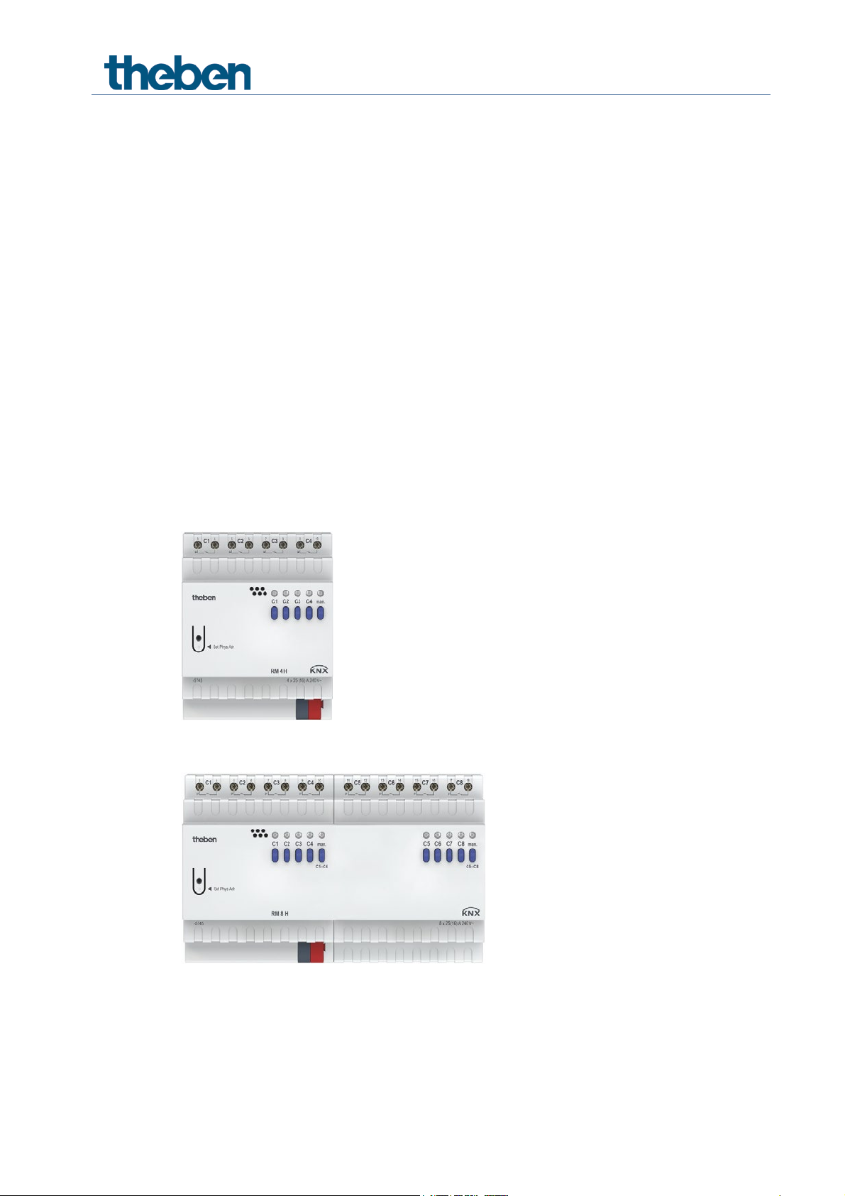
RM 4 H FIX1
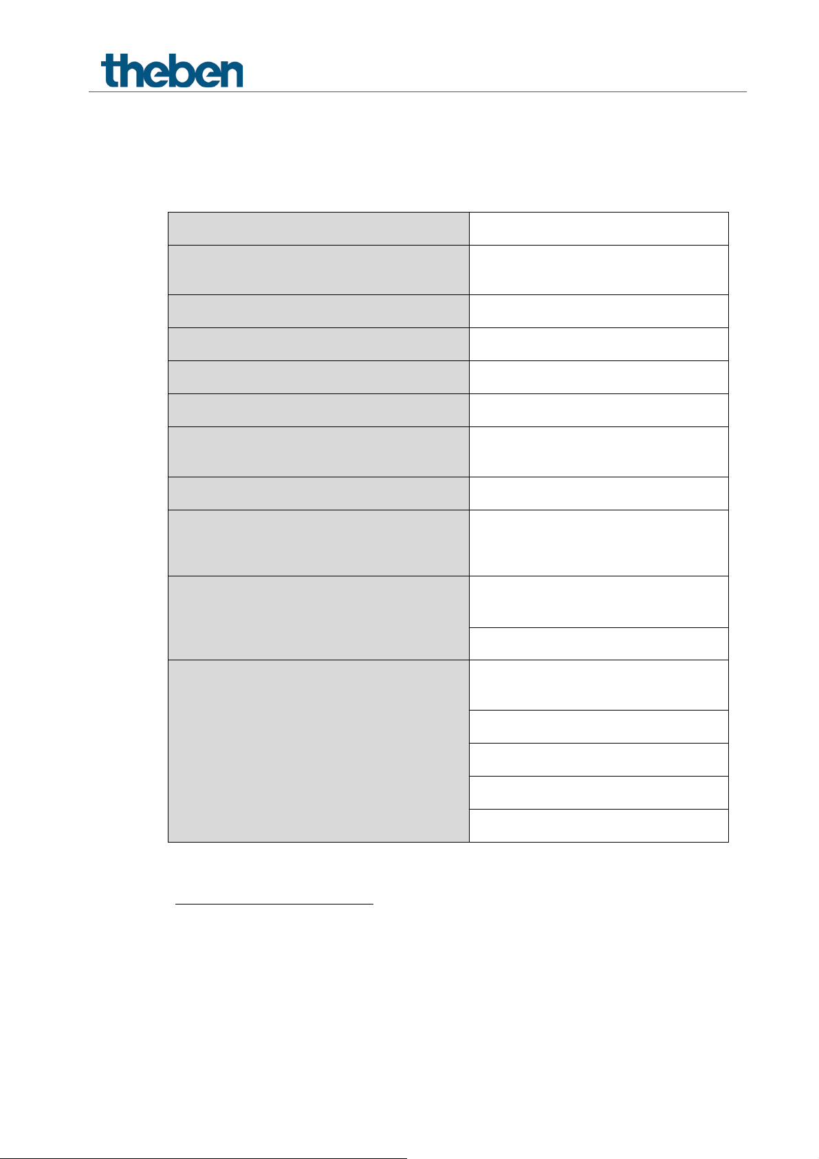
RM 8 H FIX2

Contents
1 Function description 3
2 Operation 4
3 Technical data 5
4 The FIX2 RM 8 H application programme 7
5 Typical applications 34
6 Appendix 38
4.1 Selection in the product database 7
4.2 Overview of communication objects 8
4.3 Description of communication objects 10
4.4 Parameter pages overview 15
4.5 General parameters 16
5.1 2x switching with push button interface 34
5.2 Temperature-controlled domestic water heating 36
6.1 The scenes 38
6.2 Conversion of percentages to hexadecimal and decimal values 41
KNX product manual RM 4 H, RM 8 H

1 Function description
• 4-fold FIX1 or 8-fold FIX2 switch actuator.
• Up to 25 A switching current.
• Connection cross-section up to a maximum of 6 mm
• Energy-saving thanks to bistable relay.
• No power connection required.
• LED switching status indicator for each channel.
• Manual operation on device.
• Adjustable features: e.g. switching, delayed switching, pulse function.
• Links, type of contact (NC contact/NO contact) and participation in central commands
such as permanent On, permanent Off, Central switching and save/call up scene.
• Switch functions: e.g. On/Off, pulse, On/Off delay, staircase light with forewarning.
• Logical links: e.g. block, AND, release, OR.
• Activation of the channel function via 1-bit telegram or 8-bit threshold.
2
.
Switch actuators RM 4 H, RM 8 H

2 Operation
Each channel can be switched on and off independently of all parameters using the buttons on
the device. A status LED displays the current switching status.
All bus telegrams are ignored with manual operation switched on (manual button) and the
channels are to be operated exclusively via the buttons.
Once the bus voltage has been connected or after a bus reset, it might take a few seconds until the
relays switch.
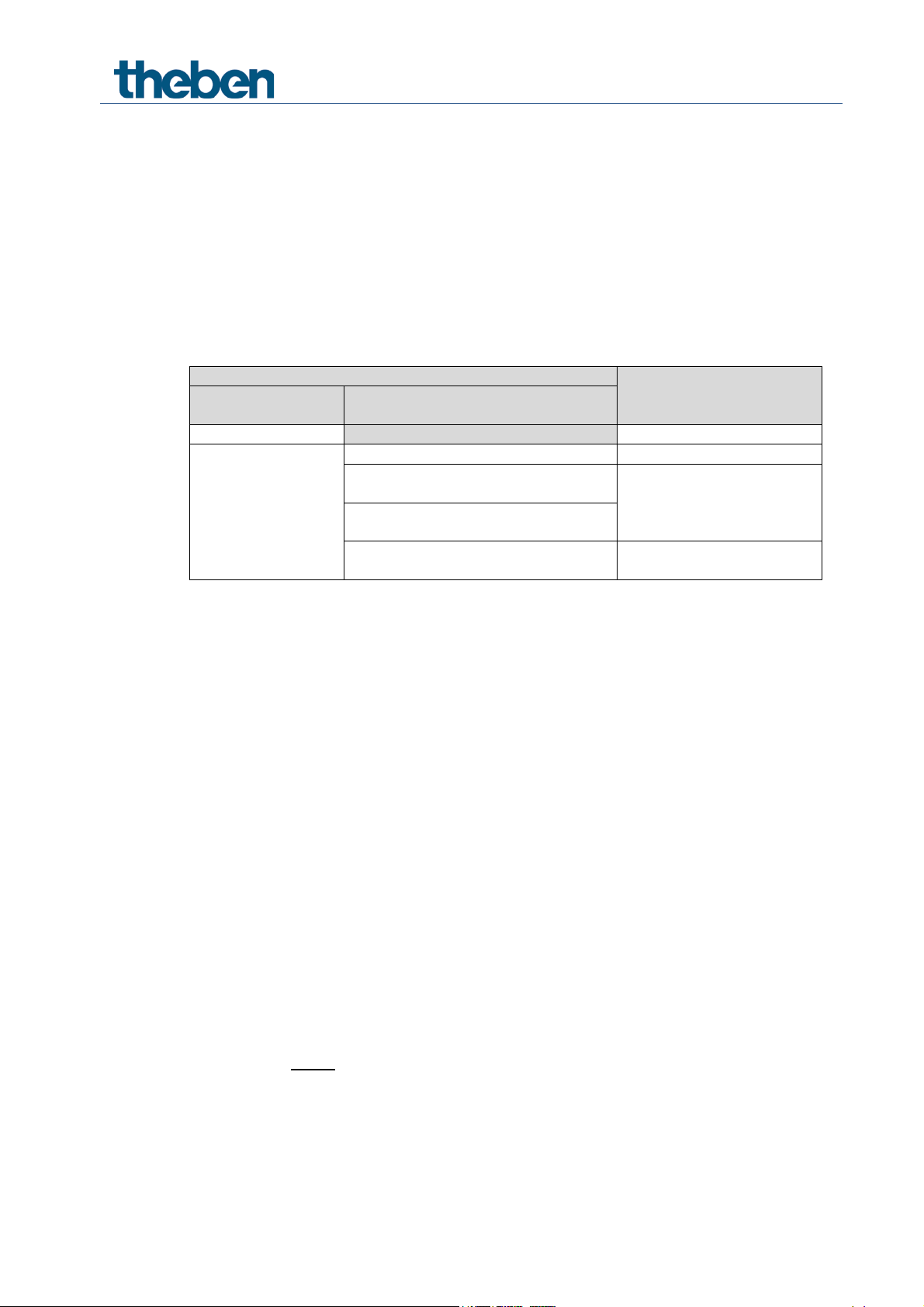
Switch actuators RM 4 H, RM 8 H
KNX bus voltage
21 – 32 V DC
Typical: 6.5 mA1, 10 mA2
Maximum: 12.5 mA3, 17.5 mA4
Number of channels
4 or 8
Type of installation
DIN-rail
Width
4 TE5 or 8 TE6
Connection type
KNX bus terminal, screw terminals
Max. cable cross-section
Solid: 6 mm² | strand with crimp terminal:
up to 4 mm²
Standby output
min. 0.17 W/0.26 W
μ-contact, floating NO contact, contact gap
25 A (at 240 V AC, cos ϕ = 1)
Minimum load
12 V/100 mA
Possible if all channels of a module
connect protective low voltage (SELV)
Protection rating
IP 20
Protection class
II subject to designated installation
Operating temperature
–5 °C … +45 °C
Incandescent/halogen lamp load
4800 W7
3 Technical data
KNX bus power input
Type of contact
Switching capacity
Switching SELV
1
RM 4 H
2
RM 8 H
3
RM 4 H
4
RM 8 H
5
RM 4 H
6
RM 8 H
7
With 30,000 switching cycles
< 3 mm; NO contact;
the switching of any phase is permitted
16 A (at 250 V AC, cos ϕ = 0.6)
Switch actuators RM 4 H, RM 8 H

Fluorescent lamps (LLB) uncompensated/series
Fluorescent lamps (LLB) parallel compensated
2500 W, 200 μF2
Fluorescent lamps (EVB)
1650 W
Compact fluorescent lamps (EVG)
410 W
LED lamps < 2 W
75 W
LED lamps 2 W – 8 W
850 W
Pollution degree
2
Rated impulse voltage
4 kV
Shortest switching interval, if all channels are
compensated
switched at the same time
5000 VA1
3 s
1
With 30,000 switching cycles
2
With 30,000 switching cycles
Switch actuators RM 4 H, RM 8 H

Manufacturer
Theben AG
Product family
Output
Product type
RM 4 H, RM 8 H
Programme name
FIX2 RM 8 H
Number of communication objects
83
Number of group addresses
254
Number of associations
255
4 The FIX2 RM 8 H application programme
4.1 Selection in the product database
The ETS database can be found on our website: www.theben.de/en/downloads_en
Switch actuators RM 4 H, RM 8 H
20
159
4.2 Overview of communication objects
4.2.1 Channel-related objects
No. Object name Function Length R W C T DPT
Switch object 1 bit R W C - 1.001
Threshold as a percentage 1 byte R W C - 5.001
0 Channel C1
1 Channel C1
2 Channel C1 Block 1 bit R W C - 1.001
3 Channel C1 Call up/save scenes 1 byte R W C T 18.001
4 Channel C1
5 Channel C1 Feedback On/Off 1 bit R - C T 1.001
6 Channel C1
7 Channel C1 Service required 1 bit R - C T 1.001
8 Channel C1
Threshold 0..255 1 byte R W C - 5.010
Threshold 0..65535 2 bytes R W C - 7.001
Threshold EIS 5 (DPT 9.xxx) 2 bytes R W C - 9.xxx
Logic input in OR gate 1 bit R W C - 1.002
Logic input in AND gate 1 bit R W C - 1.002
Logic input in XOR gate 1 bit R W C - 1.002
Block scenes = 1 1 bit R W C - 1.001
Enable scenes = 1 1 bit R W C - 1.003
Operating hours feedback 4 bytes R W C T 13.100
Time to next service 4 bytes R W C T 13.100
Reset operating hours 1 bit R W C - 1.001
Reset service 1 bit R W C - 1.001
Switching with priority 2 bit R W C - 2.001
–
Channel C2 – C8
Switch actuators RM 4 H, RM 8 H
4.2.2 Common objects
No. Object name Function Length R W C T DPT
78 C1 – C4 Manual 1 bit R W C T 1.001
79 C1 – C4 Collective feedback 4 bytes R - C T 27.001
158 C5 – C8 Manual 1 bit R W C T 1.001
159 C5 – C8 Collective feedback 4 bytes R - C T 27.001
240 Central permanent ON 1 bit R W C T 1.001
241 Central permanent OFF 1 bit R W C T 1.001
242 Central switching ON/OFF 1 bit R W C T 1.001
243 Central scenes Call up/save 1 byte R W C T 18.001
250 Version of bus coupling unit Send 14 bytes R - C T 16.001
251 Version C1 – C4 Send 14 bytes R - C T 16.001
252 Version C5 – C8 Send 14 bytes R - C T 16.001
Switch actuators RM 4 H, RM 8 H
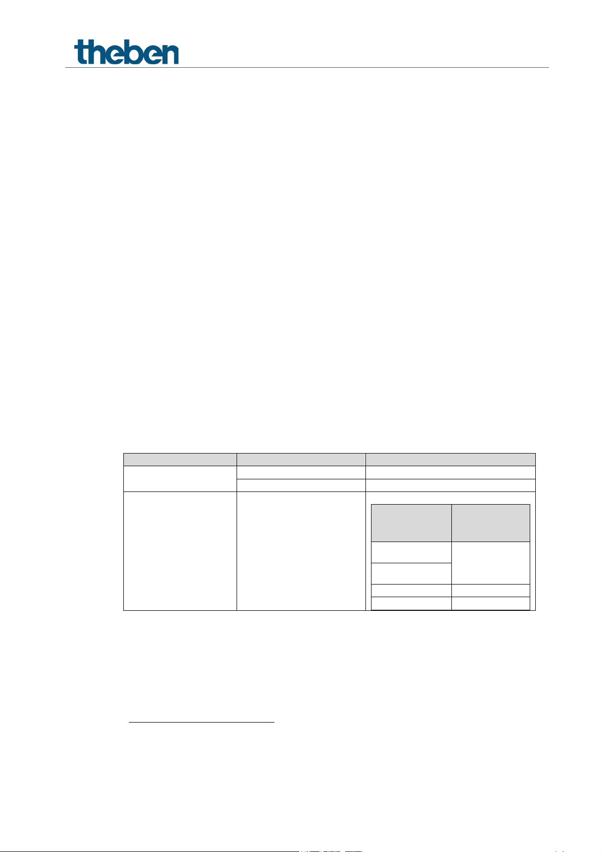
Parameter
Activation of channel
Activation of function
via
Type of threshold object
Switch object
1-bit telegram
Object type: Per cent (DPT 5.001)
Exceeding per cent value
Object type: Counter value 0..255 (DPT
5.010)
Object type: Counter value 0..65535
(DPT 7.001)
Object type: EIS5 e.g. CO2, brightness
(DPT 9.xxx)
2-byte floating-point
number
4.3 Description of communication objects
4.3.1 Channel-related objects
Object 0 Switch object, threshold as a percentage, threshold 0..255,
threshold EIS 5 (DPT 9.xxx), threshold 0..65535
Input object: this object activates the set channel function (see parameter: Channel function).
The set channel function can either be activated via 1-bit telegram or by exceeding a threshold
(8- or 16-bit telegram).
function via
Exceeding the
threshold
Object 1: Logic input in AND gate, in OR gate, in XOR gate
Only available if link is activated (Configuration options parameter page).
Forms a logical link together with the input object to activate the channel function.
Object 2: Block
Blocks the channel function.
Responses to setting and cancelling the block can be configured if the block function has been
activated (Configuration options parameter page).
Object 3: Call up/save scene
Only available if the scene function has been activated (Configuration options parameter page).
This object can be used to save and subsequently call up scenes.
Saving stores the channel status.
It does not matter how this status is produced (whether via switch commands, central objects or
the buttons on the device).
The saved status is restored when it is called up.
All scene numbers from 1 to 64 are supported.
Each channel can participate in up to 8 scenes.
See appendix: Scenes
Any value in given numerical
range
Switch actuators RM 4 H, RM 8 H
Activate hour counter
Function
Usage
Reset service1
Reset service interval counter.
Reset operating hours2
Reset hour counter
Switching with priority
Priority control:
Status of object
priority
2
OFF 3 ON
Object 4: Block scenes = 1, enable scenes = 1
Blocks the scene function with a 1 or a 0 depending on the configuration.
As long as it is blocked, scenes cannot be saved or called up.
Object 5: On/Off feedback
Reports the current channel status.
The status can also be inverted depending on configuration.
Object 6: Time to next service, operating hours feedback
Only available if the hour counter function is activated
(Configuration options parameter page).
Reports, depending on selected Type of hour counter (Hour counter and service parameter
page), either the remaining period to the next service or the current status of the hour counter.
Object 7: Service required
Only available if the hour counter function has been activated (Configuration options parameter
page) and Type of hour counter = Counter for time to next service.
Reports if the next service is due.
0 = not due
1 = service is due.
Object 8: Switching with priority, reset service, reset operating hours
The function of the object depends on whether or not the hour counter function has been
activated (Configuration options parameter page).
yes
no
1
Depending on configuration
2
Depending on configuration
Switching with
0
1
Channel status
As specified by
the input object
of the channel
Switch actuators RM 4 H, RM 8 H

Telegram
Meaning
Explanation
0
Auto
All channels can be operated via the bus as well as via the buttons.
The channels can only be operated via the buttons on the device. Bus
telegrams will not work.
4.3.2 Common objects
Objects 78, 158: Manual
Puts the corresponding channel block (C1 – C4 or C5 – C8) in manual mode or sends the status
of the manual operation.
1 Manual
Objects 79, 159: Collective feedback
Sends the current switching status of all channels in the format DPT 27.001
(DPT_CombinedInfoOnOff).
Object 240: Central permanent ON
Central switch-on function.
Enables simultaneous switching on of all channels with one single telegram.
0 = no function
1 = permanent ON
Participation in this object can be set individually for each channel
(Configuration options parameter page).
This object takes top priority.
As long as it is set, the other switch commands will not work on the participating
channels.
Object 241: Central permanent OFF
Central switch-off function.
Enables simultaneous switching off of all channels with one single telegram.
0 = no function
1 = permanent OFF
Participation in this object can be set individually for each channel
(Configuration options parameter page).
This object has the second highest priority after Central permanent ON. As long as it is
set, the other switch commands will not work on the participating channels.
Switch actuators RM 4 H, RM 8 H

Code
Meaning
xx
00 .. FF = Version of application without dividing point (10 = V1.0, 11 = V1.1, etc.).
yy
Hardware version 00..99
zzz
Firmware version 000..999
Object 242: Central switching
Central switch function.
Enables simultaneous switching on or off of all channels with one single telegram.
0 = OFF
1 = ON
Participation in this object can be set individually for each channel
(Configuration options parameter page).
With this object, every participating channel responds exactly as if its input object
were receiving a switch command.
Object 243: Call up/save central scenes
Central object for using scenes.
This object can be used to save and subsequently call up “scenes”.
See appendix: Scenes
Object 250: Version of bus coupling unit
For diagnostic purposes only.
Sends the bus coupling unit software version after reset or download.
Can also be read out directly via the ETS.
Format: Axx Hyy Vzzz
EXAMPLE: A10 H01 V001
- ETS application version 1.8
Hardware version $01
- Firmware version $001
Switch actuators RM 4 H, RM 8 H

Code
Meaning
xx
19 = Module code RM 4 H / RM 8 H (hexadecimal).
yy
Hardware version 00..99
zzz
Firmware version 000..999
Code
Meaning
xx
19 = Module code RM 4 H / RM 8 H (hexadecimal).
yy
Hardware version 00..99
zzz
Firmware version 000..999
Object 251: Version C1 – C4
For diagnostic purposes only.
Sends the software version (firmware) of the channel block C1 – C4 after reset or download.
Can also be read out directly via the ETS.
The version is issued as an ASCII character string.
Format: Mxx Hyy Vzzz
EXAMPLE: M19 H01 V001
- Module $19 = RM 4 H / RM 8 H
- Hardware version V01
- Firmware version V01
Object 252: Version C5 – C8
For diagnostic purposes only.
Sends the software version (firmware) of the channel block C5 – C8 after reset or download.
Can also be read out directly via the ETS.
The version is issued as an ASCII character string.
Format: Mxx Hyy Vzzz
EXAMPLE: M19 H01 V001
- Module $19 = RM 4 H / RM 8 H
- Hardware version V01
- Firmware version V01
Switch actuators RM 4 H, RM 8 H

Parameter page
Description
General
General parameters: Collective feedback and relay switch delay.
Channel C1
Configuration options
Characteristics of channel and activation of additional functions
(scenes, links, etc.).
Contact
characteristics
Type of contact and status after download, bus failure, etc.
Threshold
Settings for triggering channel function through exceeding threshold.
Block function
Type of block telegram and response to blocking.
Scenes
Selection of scene numbers relevant to the channel.
Feedback
Status of feedback object, etc.
Hour counter and
service
Type of hour counter and, if required, service interval, etc.
Link
Selection of logical link.
4.4 Parameter pages overview
Switch actuators RM 4 H, RM 8 H

Designation
Values
Description
Device type
RM 4 H
4-channel device FIX1
RM 8 H
8-channel device FIX2
Function of the
applies for 24 hours or
until reset via object
Determines how long the device works manually and
Manual operation
enabled
The channels can be operated via the buttons on the
device.
blocked
No manual operation, the buttons on the device are
blocked.
Sending collective
no
No collective feedback, object is unavailable.
report as inactive
Object value can be requested.
only at change
Sends whenever a channel status changes.
cyclically and at change
Sends cyclically and with status changes
See appendix: Collective feedback
Relay switch
This parameter sets the minimum delay between
are switched on simultaneously (e.g. with a number of
4.5 General parameters
4.5.1 General
manual button
of the channels
feedback
until reset via object
blocked
applies until reset via
object
applies for 30 minutes
or until reset via object
applies for 1 hour or
until reset via object
applies for 2 hours or
until reset via object
applies for 4 hours or
until reset via object
applies for 8 hours or
until reset via object
applies for 12 hours or
how this is ended.
In manual mode, the channels can only be switched
on and off via the buttons on the device.
See also: Object_78
delay
Switch actuators RM 4 H, RM 8 H
switching on 2 relays if several are activated at the
same time.
The shortest delay is achieved by using the Central
switching object.
When switching on via individual telegrams (1
telegram per channel), the bus running times and the
sequential processing of commands cause an
additional delay.
This can help avoid high current peaks when devices
lighting strips).

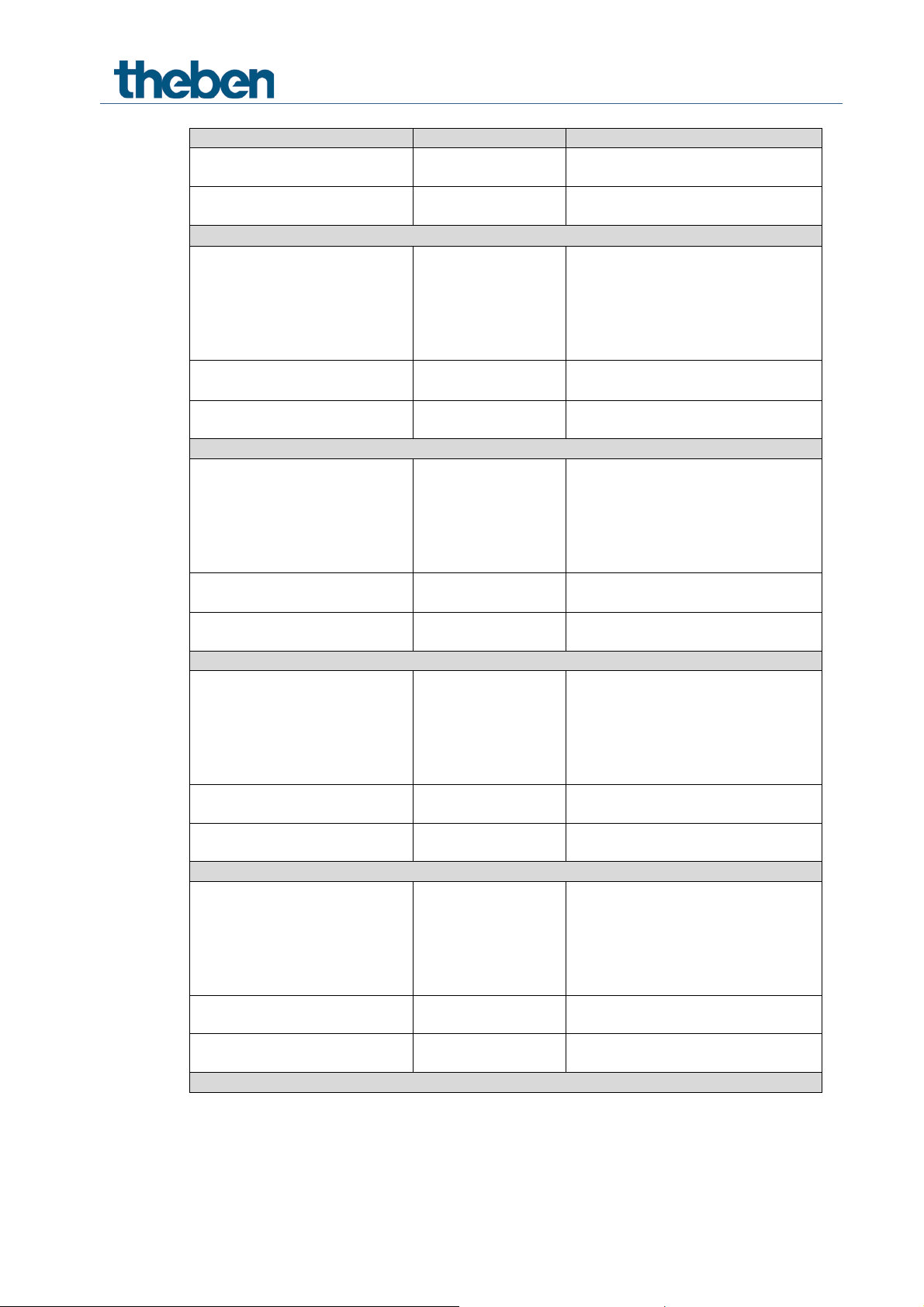
Designation
Values
Description
None
There is no added delay.
60 ms
When a relay switches on, the next one can only
on delay between the first and last relay is
Channel C4 switches 180 ms after C1.
100 ms
200 ms
switch on after the set delay is completed.
The switchcalculated according to the following formula:
(Number of channels – 1) x delay
Example:
RM 4 H and 60 ms:
= (4 channels – 1) * 60 ms = 180 ms
Switch actuators RM 4 H, RM 8 H

Designation
Values
Description
Channel function
Switching On/Off..
Flashing..
Determines the basic
Activation of function via
Switch object
The channel is
Exceeding the threshold
The channel is
page
Adjust block function
Yes..
The block function can
no
The block function
Activate scenes
Yes..
no
Should scenes be
used?
Participation in central objects
no
Central objects are not
4.5.2 Channel C1: Configuration options
A configurable copying function is not incorporated into the design.
The ETS offers convenient and extensive copying functions via the CTRL key.
On/off delay..
Pulse function..
Staircase light time switch
with forewarning function..
functionality of the
channel.
operated via a 1-bit
object.
operated through
exceeding a 1 or 2byte threshold.
See below: the
“Threshold” parameter
be individually
adjusted.
The relevant
parameter page is
shown.
Switch actuators RM 4 H, RM 8 H
works with the
standard parameters:
- Block with ON
telegram
- When setting the
block: Unchanged
- When cancelling:
Update.
taken into account.

Designation
Values
Description
at Central switching,
On and permanent OFF
Which central objects
Adjust feedback
Yes..
The feedback function
no
The Feedback function
cyclically
Activate hour counter
Yes..
Is the hour
used?
Activate link
Yes..
Are logical links to be
object?
Permanent On, Permanent
OFF
only in central permanent
ON
only in central permanent
OFF
only in Central switching
only in Central switching
and permanent ON
only in Central switching
and permanent OFF
only in central permanent
are to be taken into
account?
Central objects enable
simultaneous
switching on and off
of several channels
with one single object.
can be individually
adjusted.
The relevant
parameter page is
shown.
works with the
standard parameters:
- not inverted
- do not transmit
no
no
counter/service
interval function to be
used with the channel
Switch actuators RM 4 H, RM 8 H

Designation
Values
Description
Type of contact
NO contact
Standard:
NC contact
Inverted:
Status with download and
After download or with bus voltage
failure…
OFF ..the relay switches off.
ON ..the relay switches on.
unchanged
…the relay remains in the same state as
sufficient for an additional switching
Status with restoration of
After return of bus voltage…
OFF
..the relay is switched off.
ON
..the relay switches on.
same as before
failure
…the relay remains in the same state as
before.
4.5.3 Contact characteristics
bus failure
The relay contact is closed when a switchon command is issued.
The relay contact is opened when a switchon command is issued.
before.
If several switching operations were
executed immediately before the
bus failure, the energy may not be
operation.
In this case, the relay remains in its
previous state, regardless of the
parameter setting.
the bus supply
Switch actuators RM 4 H, RM 8 H

Designation
Values
Description
Switch-on delay
Hours
0..3
Input of desired switch-on delay in
hours.
Minutes
0..60
Input of desired switch-on delay in
minutes.
Seconds
0..255
Input of desired switch-on delay in
seconds.
Switch-off delay
Hours
0..3
Input of desired switch-off delay in
hours.
Minutes
0..60
Input of desired switch-off delay in
minutes.
Seconds
0..255
Input of desired switch-off delay in
seconds.
4.5.4 The “On/off delay” time function
This parameter page appears if On/Off delay is chosen as the Channel function.
Switch actuators RM 4 H, RM 8 H

Designation
Values
Description
Hours
0..3
Input of desired pulse duration in
hours.
Minutes
0..60
Input of desired pulse duration in
minutes.
Seconds
0..255
Input of desired pulse duration in
seconds.
Pulse can be retriggered
Yes The pulse can be extended
no
The pulse cannot be extended.
Pulse can be reset
Yes The pulse can be ended early at
no
The pulse cannot be ended early
4.5.5 The “Pulse” time function
This parameter page appears if Pulse function is chosen as the Channel function.
(with 1 on switch object)
(with 1 on switch object)
as often as desired via a 1-telegram
anytime
via a 0-telegram.
Switch actuators RM 4 H, RM 8 H

Designation
Values
Description
Staircase light time (min. 1 s)
Hours
0..3
Input of desired switch-on delay in
hours.
Minutes
0..60
Input of desired switch-on delay in
minutes.
Seconds
0..255
Input of desired switch-on delay in
seconds.
The maximum sum of pulses
1..40
Determines how often the staircase
again.
Duration of
0 The light switches off immediately
1..60
Once the staircase light time is
Duration of
0
No 2nd forewarning.
1..60
Second forewarning:
time is completed.
Flashing
Example: forewarning function
4.5.6 The “Staircase light with forewarning function” time function
This parameter page appears if Staircase light with forewarning function is chosen as the
Channel function.
The user can press a button again to extend the staircase light time at any time.
1st forewarning in s
2nd forewarning in s
Default value = 5
Default value = 10
Default value = 30
light time can be extended
(restarted) by pressing the button
once the staircase light time is
completed.
completed, the light should briefly
flash and then stay on for the
duration of the forewarning
The light switches off at the end of
the 1st forewarning.
Once the 1st forewarning is
completed, the light should flash
briefly and then stay on for the
duration of the 2nd forewarning.
The light switches off when this
Switch actuators RM 4 H, RM 8 H
Staircase light time
1st
forewarning
Flashing
2nd
forewarning
OFF

Designation
Values
Description
ON phase of flash pulse
Hours
0..3
Input of desired pulse time in hours.
Minutes
0..60
Input of desired pulse time in
minutes.
Seconds
0..255
Input of desired pulse time in
OFF phase of flash pulse
Hours
0..3
Input of desired length of break in
hours.
Minutes
0..60
Input of desired length of break in
minutes.
Seconds
0..255
Input of desired length of break in
seconds.
How often should it flash
Until it switches off
The channel flashes until a switch-
1 x
50 x
The channel flashes as often as set
4.5.7 The “Flashing” time function
This parameter page appears if Flashing is chosen as the Channel function.
seconds.
2 x
3 x
4 x
5 x
7 x
10 x
15 x
20 x
30 x
off telegram is received.
here.
Switch actuators RM 4 H, RM 8 H

Designation
Values
Description
Type of threshold object
Object type: Per cent
temperature, CO2.
Threshold format
Response on exceeding the
Should the channel switch on or off on
As switch object = 0
NO contact: the relay switches off if
threshold is exceeded.
NC contact: the relay switches on if
As switch object = 1
NO contact: the relay switches on if
NC contact: the relay switches off if
threshold is exceeded.
Parameter for Per cent threshold object
Threshold
1..99%
Desired threshold.
Object value < threshold - hysteresis
Hysteresis (as %)
1..99%
Default value = 10%
The hysteresis prevents frequent switching
after small fluctuations in readings.
Parameter for threshold object Counter value 0..255
Threshold
1..254
Desired threshold.
Object value < threshold - hysteresis
Hysteresis
1..254
Default value = 5
The hysteresis prevents frequent switching
after small fluctuations in readings.
Parameter for threshold object Counter value 0..65535
4.5.8 Threshold
This page is shown if the Activation of the function by exceeding threshold parameter is set.
(DPT 5.001)
Counter value 0..255
(DPT 5.010)
Counter value
0..65535 (DPT 7.001)
Floating point value
DPT9, e.g.
threshold
Default value = 50%
exceeding the threshold?
The set type of contact must be taken into
account here.
threshold is exceeded.
threshold is exceeded.
Example of NO contact with response as
switch object = 1:
Switches on when:
Object value > threshold
Switches off when:
Switch actuators RM 4 H, RM 8 H
Default value = 127
Example of NO contact with response as
switch object = 1:
Switches on when:
Object value > threshold
Switches off when:

Designation
Values
Description
Threshold
1..65534
Desired threshold.
Hysteresis
1..65534
The hysteresis prevents frequent switching
Parameter for Floating point value (DPT 9), e.g. temperature, CO2…) threshold object
Threshold
-671088.64..
Desired threshold.
Object value < threshold - hysteresis
Hysteresis
0.01..
Default value = 1
The hysteresis prevents frequent switching
Default value = 1000
Default value = 5
670760.96
Default value = 20
670760.96
Example of NO contact with response as
switch object = 1:
Switches on when:
Object value > threshold
Switches off when:
Object value < threshold - hysteresis
after small fluctuations in readings.
Example of NO contact with response as
switch object = 1:
Switches on when:
Object value > threshold
Switches off when:
after small fluctuations in readings.
Switch actuators RM 4 H, RM 8 H

Designation
Values
Description
Block telegram
Block with ON telegram
0 = cancel block
Block with OFF telegram
0 = block
deactivated after reset.
Response when setting the
OFF
Switch off
ON
Switch on
unchanged
No response
Response when cancelling
OFF
Switch off
ON
Switch on
unchanged
No response
update
Restore normal operation and
switch relay accordingly.
4.5.9 Block function
This page appears when Adjust block function is selected on the Configuration options
parameter page.
block
the block
1 = block
1 = cancel block
Note: The block is always
Switch actuators RM 4 H, RM 8 H

Designation
Values
Description
Block telegram for scenes
Block with ON
0 = cancel block
Block with OFF
0 = block
are always blocked immediately after
reset or download.
All channel scene statuses
Overwrite on
A download deletes all scene
Unchanged after
All previously taught-in scenes are
reacts to).
Participation in central scene
object
No
yes
Should the device react to the central
scene object?
Channel reacts to
No scene number
Scene number 63
First of the 8 possible scene numbers
Status after download
Off
New switching status to which the
Permit teach-in
No Scenes can only be called up.
Yes
The user can both call up and teach-
Channel reacts to
No scene number
Scene number 63
Second of the 8 possible scene
4.5.10 Scenes
This page appears when the Scenes are activated on the Configuration options parameter
page.
Each channel can participate in up to 8 scenes.
telegram
telegram
download
download
1 = block
1 = cancel block
Note: With this setting, the scenes
memories in a channel, i.e. all
previously taught scenes.
When a scene number is called, the
channel assumes the configured
Status after download (see below).
See appendix: Teach in scenes
without telegrams
saved.
However, the scene numbers to
which the channel should react can
be changed (see below: Channel
Switch actuators RM 4 H, RM 8 H
Scene number 1
On
Scene number 1
Scene number 2
…
to which the channel is to react.
selected scene number is to be
allocated.
Only possible if the scene statuses
are to be overwritten after download.
in or amend scenes.
numbers
Designation
Values
Description
Status after download
Off
See above.
Permit teach-in
No
See above.
Channel reacts to
No scene number
Scene number 63
Third of the 8 possible scene
Status after download
Off
See above.
Permit teach-in
No
Yes
See above.
Channel reacts to
No scene number
Scene number 63
Fourth of the 8 possible scene
Status after download
Off
On
See above.
Permit teach-in
No
Yes
See above.
Channel reacts to
No scene number
Scene number 63
Fifth of the 8 possible scene numbers
Status after download
Off
On
See above.
Permit teach-in
No
Yes
See above.
Channel reacts to
No scene number
Scene number 63
Sixth of the 8 possible scene
Status after download
Off
On
See above.
Permit teach-in
No
Yes
See above.
On
Yes
Scene number 1
…
Scene number 3
…
On
Scene number 1
…
Scene number 4
…
Scene number 1
…
Scene number 5
…
numbers
numbers
Switch actuators RM 4 H, RM 8 H
Scene number 1
…
Scene number 6
…
numbers

Designation
Values
Description
Channel reacts to
No scene number
Scene number 63
Seventh of the 8 possible scene
Status after download
Off
On
See above.
Permit teach-in
No
Yes
See above.
Channel reacts to
No scene number
Scene number 63
Last of the 8 possible scene numbers
Status after download
Off
On
See above.
Permit teach-in
No
Yes
See above.
Scene number 1
…
Scene number 7
…
Scene number 1
…
Scene number 8
…
numbers
Switch actuators RM 4 H, RM 8 H

Designation
Values
Description
Reported status
Not inverted
Channel switched on:
inverted
Channel switched on:
0
Transmit feedback cyclically
No
yes
Send at regular
intervals?
Time for cyclical transmission
2 minutes, 3 minutes,
60 minutes
At what interval?
4.5.11 Feedback
feedback object sends a
1
feedback object sends a
of feedback
5 minutes, 10 minutes,
15 minutes, 20 minutes,
30 minutes, 45 minutes
Switch actuators RM 4 H, RM 8 H

Designation
Values
Description
Type of hour counter
Hour counter
Forward counter for channel
Counter for time period
before next service
Backward counter for channel
duty cycle.
Hour counter
Reporting of operating hours
0..100
At what interval is the current
hours.
Report operating hours cyclically
No
yes
Send at regular intervals?
Time for cyclical transmission
2 minutes, 3 minutes,
60 minutes
At what interval?
Counter for time period before next service
Service interval
0..2000
Desired timescale between 2
= 100 hours
Reporting of time to service
0..100
At what interval is the current
hours.
Report time to service cyclically
no
Send remaining time to next
Report service cyclically
no
Send expiry of time to next
Time for cyclical transmission
2 minutes, 3 minutes,
60 minutes
At what interval?
4.5.12 Hour counter and service
This page appears when Activate hour counter is selected on the Configuration options
parameter page.
duty cycle.
when changing
(0..100 h, 0 = no report)
(x10 h)
when changing
(0 = no report)
Default value = 10
5 minutes, 10 minutes,
15 minutes, 20 minutes,
30 minutes, 45 minutes
Default value = 100
Default value = 10
meter reading to be sent?
Example:
10 = Send each time the meter
reading increases by another 10
services.
Example:
10 = 10 x 10 h
meter reading to be sent?
Example:
10 = Send each time the meter
reading decreases by another 10
(if used)
Switch actuators RM 4 H, RM 8 H
Yes
Yes
5 minutes, 10 minutes,
15 minutes, 20 minutes,
30 minutes, 45 minutes
service at regular intervals?
Object Time to next service.
service at regular intervals?
Object Service required.

Designation
Values
Description
Activate link
Selection of logical link with the
AND link
The Logic input in AND gate
OR link (override)
The Logic input in OR gate object
XOR link
The Logic input in XOR gate
object appears.
Block object affects logic object
No The block object only affects the
yes
The block object affects the
active.
4.5.13 Link
channel object
object appears.
appears.
input object.
If required, the logic object can
activate the channel function
despite block (with OR and XOR
link).
channel object and the logic
object.
The channel function is
completely blocked if the block is
Switch actuators RM 4 H, RM 8 H

TA 2 S
RM 4 H
Object name
Object name
5 Typical applications
These typical applications are designed to aid planning and are not to be considered an
exhaustive list.
It can be extended and updated as required.
5.1 2x switching with push button interface
2 push buttons are connected to a TA 2 S push button interface and they control 2 channels
on the RM 4 H.
5.1.1
5.1.2
5.1.3
No.
Devices
• RM 4 H (4940212)
• TA 2 S (RM 8 H (4930212))
Overview
Objects and links
No.
Comment
1 Channel I1.1 switching 0 Channel C1 switch object -
11 Channel I2.1 switching 20 Channel C2 switch object -
Switch actuators RM 4 H, RM 8 H

Parameter page
Parameter
Setting
Channel 1
Activate channel 1
Yes
Channel 1 function
Push button
Button object 1
Object type
Switching (1 bit)
Send after short operation
Send telegram
Value
Change over
Send after long operation
Do not send
Send after double-click
Do not send
Channel 2
Activate channel 2
Yes
Channel 2 function
Push button
Button object 1
Object type
Switching (1 bit)
Send after short operation
Send telegram
Value
Change over
Send after long operation
Do not send
Send after double-click
Do not send
Parameter page
Parameter
Setting
Channel C1
Channel function
Switch On/Off
Activation of function via
Switch object
Contact characteristics
Type of contact
NO contact
5.1.4 Important parameter settings
Standard or customer-defined parameter settings apply to unlisted parameters.
TA 2 S:
RM 4 H:
Switch actuators RM 4 H, RM 8 H
TA 4 S
RM 4 H
Object name
Object name
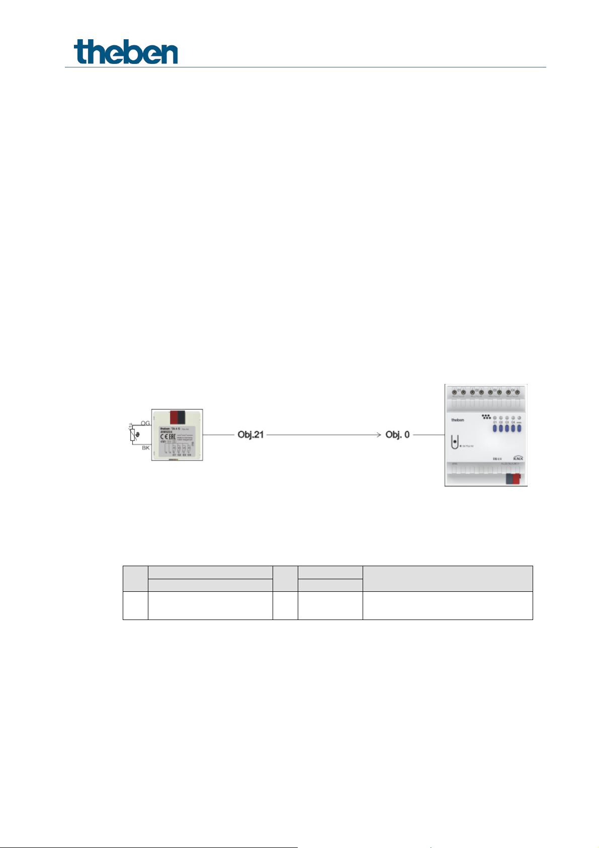
5.2 Temperature-controlled domestic water heating
Task:
The domestic water temperature must be maintained at a minimum of 50 °C using a heating
element.
The water temperature is measured using a remote sensor (e.g. order no. 9070321).
The sensor is connected to a TA 4 S input and the temperature value is sent to the bus.
Channel C1 receives the domestic water temperature via a threshold object and switches the
heating element to relay output.
5.2.1
5.2.2
5.2.3
Devices
• RM 4 H (4940212)
• TA 4 S (RM 8 H (4930214))
• 100k feed temperature sensor (9070489)
Overview
Objects and links
No.
Temperature actual value
21
of channel I3
Switch actuators RM 4 H, RM 8 H
No.
0
DPT 9
threshold
Comment
The measured temperature is sent to
the threshold object.

Parameter page
Parameter
Setting
Channel 3
Activate channel 3
Yes
Channel 3 function
Temperature input
Sensor type
Floor sensor (9070321)
Transmit temperature in the event of change of
2 K
Parameter page
Parameter
Setting
Configuration
options
Channel function
Switch On/Off
Activation of function via
Exceeding the setpoint
Contact
characteristics
Type of contact
NO contact
Threshold
Type of threshold object
Floating point value DPT9, e.g.
temperature, CO2.
Threshold
50
Hysteresis
5
Response on exceeding the
threshold
As switch object = 0
5.2.4 Important parameter settings
Standard or customer-defined parameter settings apply to unlisted parameters.
TA 4 S:
Temperature input
RM 4 H, channel C1:
Switch actuators RM 4 H, RM 8 H

6 Appendix
6.1 The scenes
6.1.1 Principle
The current status of a channel, or a complete
device can be stored and retrieved later at any time via the scene function.
Each channel can participate simultaneously in up to 8 scenes.
Scene numbers 1 to 64 are permitted.
Permission is required to access scenes for the relevant channel via parameter.
See Activate scenes parameter and Scenes parameter page.
The current status is allocated to the appropriate scene number when a scene is saved.
The previously saved status is restored when a scene number is called up.
This allows a FIX system to be easily and conveniently integrated into any chosen user scene.
The scenes are permanently stored and remain intact even after the application has been
downloaded again.
See All channel scene statuses parameter on the Scenes parameter page.
Switch actuators RM 4 H, RM 8 H

Call up
Save
Hex.
Dec.
Hex.
Dec. 1 $00 0 $80
128 2 $01 1 $81
129
3
$02 2 $82
130
4
$03 3 $83
131 5 $04 4 $84
132 6 $05 5 $85
133 7 $06 6 $86
134 8 $07 7 $87
135
9
$08 8 $88
136
10
$09 9 $89
137
11
$0A
10
$8A
138
12
$0B
11
$8B
139
13
$0C
12
$8C
140
14
$0D
13
$8D
141
15
$0E
14
$8E
142
16
$0F
15
$8F
143
17
$10
16
$90
144
18
$11
17
$91
145
19
$12
18
$92
146
20
$13
19
$93
147
21
$14
20
$94
148
22
$15
21
$95
149
23
$16
22
$96
150
24
$17
23
$97
151
25
$18
24
$98
152
26
$19
25
$99
153
27
$1A
26
$9A
154
28
$1B
27
$9B
155
29
$1C
28
$9C
156
30
$1D
29
$9D
157
31
$1E
30
$9E
158
32
$1F
31
$9F
159
33
$20
32
$A0
160
34
$21
33
$A1
161
35
$22
34
$A2
162
36
$23
35
$A3
163
37
$24
36
$A4
164
38
$25
37
$A5
165
39
$26
38
$A6
166
40
$27
39
$A7
167
41
$28
40
$A8
168
42
$29
41
$A9
169
43
$2A
42
$AA
170
44
$2B
43
$AB
171
45
$2C
44
$AC
172
46
$2D
45
$AD
173
47
$2E
46
$AE
174
6.1.2 Calling up or saving scenes:
To call up or save a scene, the relevant code is sent to the corresponding scene object.
Scenario
Switch actuators RM 4 H, RM 8 H

Call up
Save
Hex.
Dec.
Hex.
Dec.
48
$2F
47
$AF
175
49
$30
48
$B0
176
50
$31
49
$B1
177
51
$32
50
$B2
178
52
$33
51
$B3
179
53
$34
52
$B4
180
54
$35
53
$B5
181
55
$36
54
$B6
182
56
$37
55
$B7
183
57
$38
56
$B8
184
58
$39
57
$B9
185
59
$3A
58
$BA
186
60
$3B
59
$BB
187
61
$3C
60
$BC
188
62
$3D
61
$BD
189
63
$3E
62
$BE
190
64
$3F
63
$BF
191
Scenario
Examples (central or channel-related):
Call up status of scene 5:
→ Send $04 to the relevant scene object.
Save current status with scene 5:
→ Send $84 to the relevant scene object.
Switch actuators RM 4 H, RM 8 H

Percentage
value
Hexadecimal
00
1A
33
4D
66
80
99
B3
CC
E6
FF
Decimal
00
26
51
77
102
128
153
179
204
230
255
6.1.3 Teach-in scenes without telegrams
Instead of defining scenes individually by telegram, this can be done in advance in the ETS.
This merely requires setting the All channel scene statuses parameter (Scenes parameter page)
to overwrite at download.
Accordingly, the required status can be selected for each of the 8 possible scene numbers in a
channel (= Status after download parameter).
The scenes are programmed into the device after the download has been completed.
Later changes via teach in telegrams are possible if required and they can be permitted or
blocked via a parameter.
6.2 Conversion of percentages to hexadecimal and decimal
values
0% 10% 20% 30% 40% 50% 60% 70% 80% 90% 100%
All values from 00 to FF hex. (0 to 255 dec.) are valid.
Switch actuators RM 4 H, RM 8 H
 Loading...