

Theben RM 4 H FIX1, RM 8 H FIX2 User Manual
2018-07-30
4940212
4940217
KNX manual
High-performance switch actuators
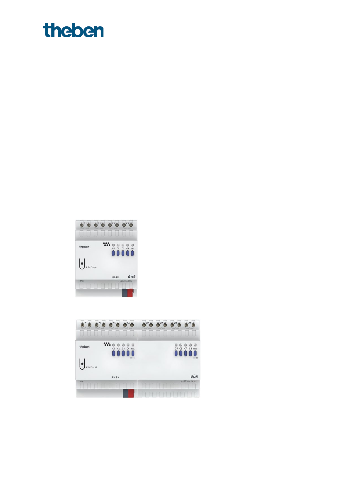
RM 4 H FIX1
RM 8 H FIX2

Contents
1 Function description 3
2 Operation 4
3 Technical data 5
4 The FIX2 RM 8 H application programme 7
5 Typical applications 34
6 Appendix 38
4.1 Selection in the product database 7
4.2 Overview of communication objects 8
4.3 Description of communication objects 10
4.4 Parameter pages overview 15
4.5 General parameters 16
5.1 2x switching with push button interface 34
5.2 Temperature-controlled domestic water heating 36
6.1 The scenes 38
6.2 Conversion of percentages to hexadecimal and decimal values 41
KNX product manual RM 4 H, RM 8 H

1 Function description
• 4-fold FIX1 or 8-fold FIX2 switch actuator.
• Up to 25 A switching current.
• Connection cross-section up to a maximum of 6 mm
• Energy-saving thanks to bistable relay.
• No power connection required.
• LED switching status indicator for each channel.
• Manual operation on device.
• Adjustable features: e.g. switching, delayed switching, pulse function.
• Links, type of contact (NC contact/NO contact) and participation in central commands
such as permanent On, permanent Off, Central switching and save/call up scene.
• Switch functions: e.g. On/Off, pulse, On/Off delay, staircase light with forewarning.
• Logical links: e.g. block, AND, release, OR.
• Activation of the channel function via 1-bit telegram or 8-bit threshold.
2
.
Switch actuators RM 4 H, RM 8 H

2 Operation
Each channel can be switched on and off independently of all parameters using the buttons on
the device. A status LED displays the current switching status.
All bus telegrams are ignored with manual operation switched on (manual button) and the
channels are to be operated exclusively via the buttons.
Once the bus voltage has been connected or after a bus reset, it might take a few seconds until the
relays switch.
Switch actuators RM 4 H, RM 8 H

KNX bus voltage
21 – 32 V DC
Typical: 6.5 mA1, 10 mA2
Maximum: 12.5 mA3, 17.5 mA4
Number of channels
4 or 8
Type of installation
DIN-rail
Width
4 TE5 or 8 TE6
Connection type
KNX bus terminal, screw terminals
Max. cable cross-section
Solid: 6 mm² | strand with crimp terminal:
up to 4 mm²
Standby output
min. 0.17 W/0.26 W
μ-contact, floating NO contact, contact gap
25 A (at 240 V AC, cos ϕ = 1)
Minimum load
12 V/100 mA
Possible if all channels of a module
connect protective low voltage (SELV)
Protection rating
IP 20
Protection class
II subject to designated installation
Operating temperature
–5 °C … +45 °C
Incandescent/halogen lamp load
4800 W7
3 Technical data
KNX bus power input
Type of contact
Switching capacity
Switching SELV
1
RM 4 H
2
RM 8 H
3
RM 4 H
4
RM 8 H
5
RM 4 H
6
RM 8 H
7
With 30,000 switching cycles
< 3 mm; NO contact;
the switching of any phase is permitted
16 A (at 250 V AC, cos ϕ = 0.6)
Switch actuators RM 4 H, RM 8 H

Fluorescent lamps (LLB) uncompensated/series
Fluorescent lamps (LLB) parallel compensated
2500 W, 200 μF2
Fluorescent lamps (EVB)
1650 W
Compact fluorescent lamps (EVG)
410 W
LED lamps < 2 W
75 W
LED lamps 2 W – 8 W
850 W
Pollution degree
2
Rated impulse voltage
4 kV
Shortest switching interval, if all channels are
compensated
switched at the same time
5000 VA1
3 s
1
With 30,000 switching cycles
2
With 30,000 switching cycles
Switch actuators RM 4 H, RM 8 H

Manufacturer
Theben AG
Product family
Output
Product type
RM 4 H, RM 8 H
Programme name
FIX2 RM 8 H
Number of communication objects
83
Number of group addresses
254
Number of associations
255
4 The FIX2 RM 8 H application programme
4.1 Selection in the product database
The ETS database can be found on our website: www.theben.de/en/downloads_en
Switch actuators RM 4 H, RM 8 H
20
159
4.2 Overview of communication objects
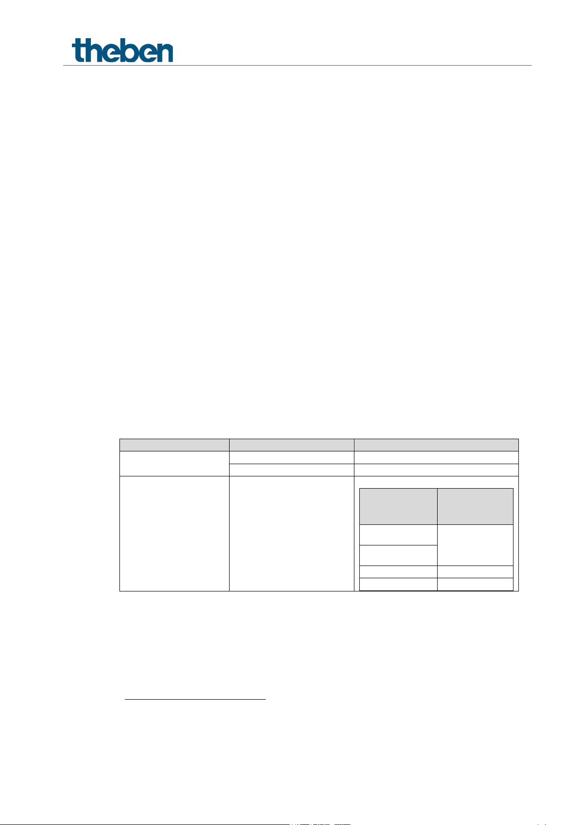
4.2.1 Channel-related objects
No. Object name Function Length R W C T DPT
Switch object 1 bit R W C - 1.001
Threshold as a percentage 1 byte R W C - 5.001
0 Channel C1
1 Channel C1
2 Channel C1 Block 1 bit R W C - 1.001
3 Channel C1 Call up/save scenes 1 byte R W C T 18.001
4 Channel C1
5 Channel C1 Feedback On/Off 1 bit R - C T 1.001
6 Channel C1
7 Channel C1 Service required 1 bit R - C T 1.001
8 Channel C1
Threshold 0..255 1 byte R W C - 5.010
Threshold 0..65535 2 bytes R W C - 7.001
Threshold EIS 5 (DPT 9.xxx) 2 bytes R W C - 9.xxx
Logic input in OR gate 1 bit R W C - 1.002
Logic input in AND gate 1 bit R W C - 1.002
Logic input in XOR gate 1 bit R W C - 1.002
Block scenes = 1 1 bit R W C - 1.001
Enable scenes = 1 1 bit R W C - 1.003
Operating hours feedback 4 bytes R W C T 13.100
Time to next service 4 bytes R W C T 13.100
Reset operating hours 1 bit R W C - 1.001
Reset service 1 bit R W C - 1.001
Switching with priority 2 bit R W C - 2.001
–
Channel C2 – C8
Switch actuators RM 4 H, RM 8 H
4.2.2 Common objects
No. Object name Function Length R W C T DPT
78 C1 – C4 Manual 1 bit R W C T 1.001
79 C1 – C4 Collective feedback 4 bytes R - C T 27.001
158 C5 – C8 Manual 1 bit R W C T 1.001
159 C5 – C8 Collective feedback 4 bytes R - C T 27.001
240 Central permanent ON 1 bit R W C T 1.001
241 Central permanent OFF 1 bit R W C T 1.001
242 Central switching ON/OFF 1 bit R W C T 1.001
243 Central scenes Call up/save 1 byte R W C T 18.001
250 Version of bus coupling unit Send 14 bytes R - C T 16.001
251 Version C1 – C4 Send 14 bytes R - C T 16.001
252 Version C5 – C8 Send 14 bytes R - C T 16.001
Switch actuators RM 4 H, RM 8 H
Parameter
Activation of channel
Activation of function
via
Type of threshold object
Switch object
1-bit telegram
Object type: Per cent (DPT 5.001)
Exceeding per cent value
Object type: Counter value 0..255 (DPT
5.010)
Object type: Counter value 0..65535
(DPT 7.001)
Object type: EIS5 e.g. CO2, brightness
(DPT 9.xxx)
2-byte floating-point
number
4.3 Description of communication objects
4.3.1 Channel-related objects
Object 0 Switch object, threshold as a percentage, threshold 0..255,
threshold EIS 5 (DPT 9.xxx), threshold 0..65535
Input object: this object activates the set channel function (see parameter: Channel function).
The set channel function can either be activated via 1-bit telegram or by exceeding a threshold
(8- or 16-bit telegram).
function via
Exceeding the
threshold
Object 1: Logic input in AND gate, in OR gate, in XOR gate
Only available if link is activated (Configuration options parameter page).
Forms a logical link together with the input object to activate the channel function.
Object 2: Block
Blocks the channel function.
Responses to setting and cancelling the block can be configured if the block function has been
activated (Configuration options parameter page).
Object 3: Call up/save scene
Only available if the scene function has been activated (Configuration options parameter page).
This object can be used to save and subsequently call up scenes.
Saving stores the channel status.
It does not matter how this status is produced (whether via switch commands, central objects or
the buttons on the device).
The saved status is restored when it is called up.
All scene numbers from 1 to 64 are supported.
Each channel can participate in up to 8 scenes.
See appendix: Scenes
Any value in given numerical
range
Switch actuators RM 4 H, RM 8 H
Activate hour counter
Function
Usage
Reset service1
Reset service interval counter.
Reset operating hours2
Reset hour counter
Switching with priority
Priority control:
Status of object
priority
2
OFF 3 ON
Object 4: Block scenes = 1, enable scenes = 1
Blocks the scene function with a 1 or a 0 depending on the configuration.
As long as it is blocked, scenes cannot be saved or called up.
Object 5: On/Off feedback
Reports the current channel status.
The status can also be inverted depending on configuration.
Object 6: Time to next service, operating hours feedback
Only available if the hour counter function is activated
(Configuration options parameter page).
Reports, depending on selected Type of hour counter (Hour counter and service parameter
page), either the remaining period to the next service or the current status of the hour counter.
Object 7: Service required
Only available if the hour counter function has been activated (Configuration options parameter
page) and Type of hour counter = Counter for time to next service.
Reports if the next service is due.
0 = not due
1 = service is due.
Object 8: Switching with priority, reset service, reset operating hours
The function of the object depends on whether or not the hour counter function has been
activated (Configuration options parameter page).
yes
no
1
Depending on configuration
2
Depending on configuration
Switching with
0
1
Channel status
As specified by
the input object
of the channel
Switch actuators RM 4 H, RM 8 H

Telegram
Meaning
Explanation
0
Auto
All channels can be operated via the bus as well as via the buttons.
The channels can only be operated via the buttons on the device. Bus
telegrams will not work.
4.3.2 Common objects
Objects 78, 158: Manual
Puts the corresponding channel block (C1 – C4 or C5 – C8) in manual mode or sends the status
of the manual operation.
1 Manual
Objects 79, 159: Collective feedback
Sends the current switching status of all channels in the format DPT 27.001
(DPT_CombinedInfoOnOff).
Object 240: Central permanent ON
Central switch-on function.
Enables simultaneous switching on of all channels with one single telegram.
0 = no function
1 = permanent ON
Participation in this object can be set individually for each channel
(Configuration options parameter page).
This object takes top priority.
As long as it is set, the other switch commands will not work on the participating
channels.
Object 241: Central permanent OFF
Central switch-off function.
Enables simultaneous switching off of all channels with one single telegram.
0 = no function
1 = permanent OFF
Participation in this object can be set individually for each channel
(Configuration options parameter page).
This object has the second highest priority after Central permanent ON. As long as it is
set, the other switch commands will not work on the participating channels.
Switch actuators RM 4 H, RM 8 H

Code
Meaning
xx
00 .. FF = Version of application without dividing point (10 = V1.0, 11 = V1.1, etc.).
yy
Hardware version 00..99
zzz
Firmware version 000..999
Object 242: Central switching
Central switch function.
Enables simultaneous switching on or off of all channels with one single telegram.
0 = OFF
1 = ON
Participation in this object can be set individually for each channel
(Configuration options parameter page).
With this object, every participating channel responds exactly as if its input object
were receiving a switch command.
Object 243: Call up/save central scenes
Central object for using scenes.
This object can be used to save and subsequently call up “scenes”.
See appendix: Scenes
Object 250: Version of bus coupling unit
For diagnostic purposes only.
Sends the bus coupling unit software version after reset or download.
Can also be read out directly via the ETS.
Format: Axx Hyy Vzzz
EXAMPLE: A10 H01 V001
- ETS application version 1.8
Hardware version $01
- Firmware version $001
Switch actuators RM 4 H, RM 8 H
 Loading...