

Theben RAMSES 818 top 6 A, RAMSES 818 top 16 A Operating Instructions Manual
Bedienungsanleitung 1
Uhrenthermostat
Operating instructions 16
Clock thermostat
Mode d’emploi 31
Thermostat à horloge
Instrucciones de servicio 46
Cronotermostato
Istruzioni per l’uso 61
Cronotermostato
Gebruiksaanwijzing 76
Klokthermostaat
RAMSES 818 top 6 A
RAMSES 818 top 16 A
309 251 05
Table of Contents
1 Designated Use ....................................................................15
2 Safety Instructions...............................................................1 5
3 Description and Mounting................................................... 16
3.1 Device Overview .................................................................... 16
3.2 Mounting and Electrical Connection....................................... 17
4 Installation and Operation................................................... 18
4.1 Carrying out a Reset .............................................................. 18
4.2 Inserting or Exchanging Batteries (only RAMSES®811 top)18
4.3 Selecting the Language .........................................................18
4.4 Setting the Time / Date .......................................................... 18
4.5 Selecting the Temperature Profile.......................................... 19
4.6 Checking Current Room Temperature and Settings -
Info Button.............................................................................. 19
4.7 Temporarily Changing the Target Temperature..................... 20
4.8 Early Cancellation, Check or Clearance of the
Holiday Program .................................................................... 20
4.9 Party / Eco Program............................................................... 21
5 Programming........................................................................ 21
5.1 Setting the Holiday Program.................................................. 21
5.2 Changing the Settings for Target Temperatures.................... 22
5.3 Program P3............................................................................22
5.4 Service Settings ..................................................................... 25
5.5 Time/Date and Summer/Winter Time..................................... 27
6 Maintenance and Repair...................................................... 28
7 Disposal ................................................................................ 28
7.1 Disposal of Batteries .............................................................. 28
7.2 Disposal of the Device ...........................................................28
8 Technical Data......................................................................2 8
1DesignatedUse
The RAMSES®811/812 top is a digital clock thermostat for control-
ling the room temperature.
The room thermostat RAMSES
®
811/812 top is intended for time-
and room temperature-dependent on andoff switching ofan electrical
load with a maximum current consumption of 6 A, such as a circula-
tion pump, a burner or a motor mixing valve. It must only be used in
dry rooms with impurities that are usual for flats or houses.
Designated use also includes adherence to the operating and mount-
ing instructions. Any other usage is not allowed. The manufacturer
cannot be held liable for damages resulting from this.
2 Safety Instructions
The connection and installation of electrical devices must
only be carried out by a qualified technician.
The national regulations and respective safety instruc-
tions are to be observed.
Interferences and changes to the device will lead to can-
cellation of the warranty.
Table of Contents
1 Designated Use. . …………………………...…….……………..16
2 Safety Instructions. . …………………………………………....16
3 Description and Mounting…………………………………… . 17
3.1 Device Overview . . . . . . . . . . . . . . . . . . . . . . . . . . . . . . . . . . . . . . . . . . 17
3.2 Mounting and Electrical Connection . . . . . . . . . . . . . . . . . . . . . . . . . . . 18
4 Installation and Operation . . . . . . . . . . . . . . . . . . . . . . . . . . . . 19
4.1 Carrying out a Reset . . . . . . . . . . . . . . . . . . . . . . . . . . . . . . . . . . . . . . . 19
4.2 Selecting the Language. . . . . . . . . . . . . . . . . . . . . . . . . . . . . . . . . . . . . 19
4.3 Select the floor covering and/or the control range . . . . . . . . . . . . . . . . 19
4.4 Setting the Time/Date . . . . . . . . . . . . . . . . . . . . . . . . . . . . . . . . . . . . . . 19
4.5 Selecting the Temperature Profile . . . . . . . . . . . . . . . . . . . . . . . . . . . . 20
4.6 Checking Current Room Temperature and Settings - Info Button . . . . 20
4.7 Quick-heating function (boost function) . . . . . . . . . . . . . . . . . . . . . . . . 21
4.8 Temporarily Changing the Target Temperature . . . . . . . . . . . . . . . . . . . 21
4.9 Early Cancellation, Check or Clearance of the
Holiday Program . . . . . . . . . . . . . . . . . . . . . . . . . . . . . . . . . . . . . . . . . 21
4.10 Party/Eco Program. . . . . . . . . . . . . . . . . . . . . . . . . . . . . . . . . . . . . . . . . 22
5 Programming . . . . . . . . . . . . . . . . . . . . . . . . . . . . . . . . . . . . . . 22
5.1 Setting the Holiday Program . . . . . . . . . . . . . . . . . . . . . . . . . . . . . . . . 22
5.2 Changing the Settings for Target Temperatures . . . . . . . . . . . . . . . . . . 23
5.3 Program P1, P2, P3 . . . . . . . . . . . . . . . . . . . . . . . . . . . . . . . . . . . . . . . 23
5.4 Service Settings. . . . . . . . . . . . . . . . . . . . . . . . . . . . . . . . . . . . . . . . . . . 26
5.5 Time/Date and Summer/Winter Time . . . . . . . . . . . . . . . . . . . . . . . . . . 29
6 Maintenance and Repair . . . . . . . . . . . . . . . . . . . . . . . . . . . . . . 30
7 Disposal . . . . . . . . . . . . . . . . . . . . . . . . . . . . . . . . . . . . . . . . . . . 30
8 Technical Data . . . . . . . . . . . . . . . . . . . . . . . . . . . . . . . . . . . . . . 30
1 Designated Use
RAMSES®818 top 6 A and RAMSES®818 top 16 A are digital
clock thermostats for regulating the temperature.
The temperature is measured via a 4 m external temperature sensor.
The clock thermostats are used in electric underfloor heaters or floor
temperature regulating systems.
The thermostats RAMSES®818 top 6 A/16 A are intended for
time and temperature-dependent on and off switching of an electrical
load with a current consumption of 6 A/16 A. It must only be used in
dry rooms with impurities that are usual for flats or houses.
Designated use also includes adherence to the operating and mounting instructions.Any other usage is not allowed. The manufacturer
cannot be held liable for damages resulting from this.
2 Safety Instructions
To be able to eliminate all fire hazards and the risk of
electric shock, the device must be connected and installed
by a qualified electrician and in accordance with the natio-
nal regulations and valid safety requirements.
Tampering with or making modifications to the device will invalidate
the guarantee.
16
ENGLISH
3 Description and Mounting
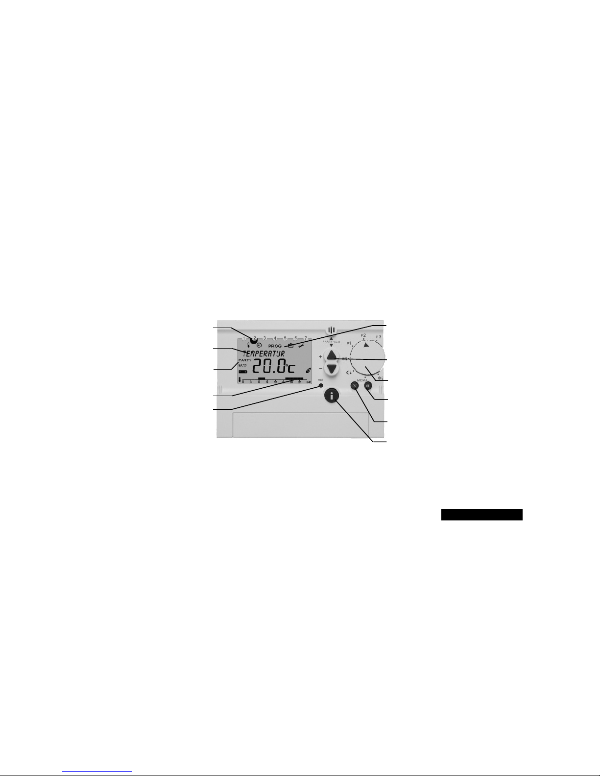
3.1 Device Overview
Display of the day of week
(1 = Monday, 2 = Tuesday etc.)
Multifunctional display,
e.g. “Room temperature 20.O ˚C”
Display PARTY or
ECO program active
Display of the switch phases
RESET button
Icon bar for display of the programming
level (rotary switch position MENU)
Change buttons +/–
Rotary switch for program selection
Button OK (confirmation of settings/
selection or programming )
Button ESC (cancellation of
programming entries)
Info button for checking the settings
17
ENGLISH
18
ENGLISH
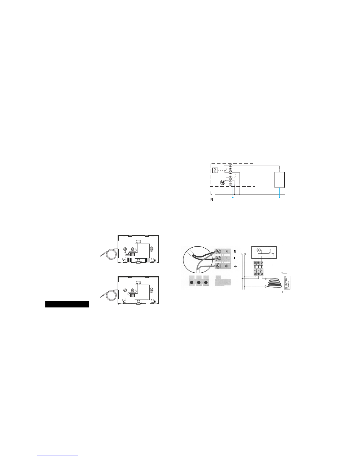
3.2 Mounting and Electrical Connection
3.2.1 Connection (and mounting) of the temperature
floor sensor
– The temperature floor sensor should be placed in the floor in a
„PVC“ tube between the heating cables.
– The sensor device cable must not be laid together with a voltage-
carrying cable in an empty tube.
Attention!
– Make use of a original floor sensor only!
– The sensor cable should not be lengthened!
– The sensor cable may be shortened. before doing so, make sure that
the temperature regulator is disconnected!
– We strongly recommend to implement on extra security for the
regulator system through installing a personal protection switch!
RAMSES 818 top 16 A
RAMSES 818 top 6 A
3.2.2 Connection examples RAMSES®818 top 6 A
3.2.3 Connection examples RAMSES®818 top 16 A
flush-mounted
socket
N
L1
heating cable
Regulation of an
underfloor heating cable or a
heating mat
Heating mat
Connection
– Remove the connection cable from the terminal.
– Now attach the connection cable (see figure).
Connect the temperature sensor according to the connection diagram.
4 Installation and Operation
For installation of RAMSES®818 top, follow the sections
4.1 to 4.4.
4.1 Carrying out a Reset
After having connected the power supply or having inserted the batteries (when exceeding the battery change power reserve of 10 min),
you must carry out a Reset. For this purpose, open the hinged cover,
and press with a pointed object on the Reset button which is recessed in the case (see figure below).
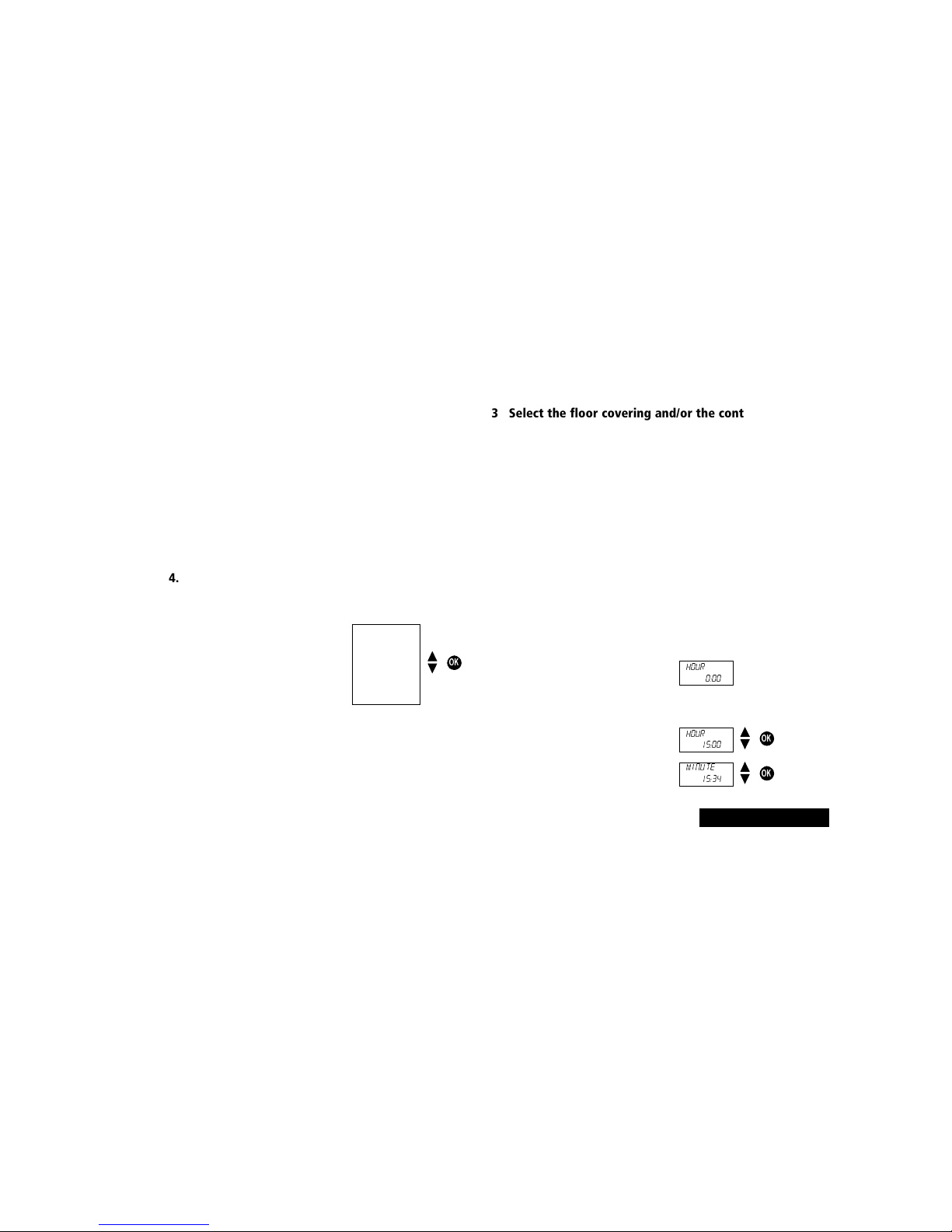
4.4 Setting the Time / Date
With the ESC button you can always return to the previous programmming step in order to adjust a setting.
3. The display automatically switches to the time setting.
Note: The language can also be changed in the “Service” menu
(see chap. 5.4).
1. The display shows the time setting.
2. Set the current time with the buttons
▲ and ▼:
Set the hour and confirm with the OK
button.
Set the minutes and confirm with the
OK button.
19
ENGLISH
OK
4.2 Selecting the Language
1. The display automatically shows the selected language
after Reset.
2. Select your language with the buttons
▲ or ▼. The available languages are
displayed one after the other.
Confirm with the OK button.
nederlands
francais
english
deutsch
italiano
espanol
portugues
Hour
0:00
OK
Hour
15:00
OK
Minute
15:34
4.3 Select the floor covering and/or the control
range
1. Select the floor covering with the ▲ or ▼ button.
2. Press OK to confirm.
Recommended control range:
– Floor covering-1 (5–30 °C)
wood, cork, laminate, PVC and carpeting
– Floor covering-2 (5–40 °C)
stone, earthenware, ceramic coverings

Note: The time and date can also be changed in the “Service” menu
(see chap. 5.4).There you can also set the changeover from winter to
summer time.
4.5 Selecting the Temperature Profile
4.5.1 Program P1 (freely selectable)
Comfort temperature Mon-Fr from 5.30 - 9.00 and
21.00 - 23.00 hrs; Sat and Sun 7.00 - 11.00 and
21.00 - 23.00 hrs; in between lower temperature
4.5.2 Program P2 (freely selectable)
Comfort temperature Mon-Fr from 5.30 - 8.00 and 16.00 - 22.00 hrs;
Sat and Sun 6.00 - 8.00 and 16.00 - 23.00 hrs.
4.5.3 Program P3 (freely selectable)
The program P3 is an individually programmable temperature profile.
Program P3 is not programmed when delivered. For programming
see chap. 5.
4.5.4 Permanent comfort (using Comfort + Reduced 1)
The room temperature is permanently regulated to the programmed
comfort temperature.There is no reduction.
4.5.5 Permanent reduction (using Comfort + Reduced 1)
The room temperature is permanently regulated to the programmed
lower temperature.
4.5.6 Antifreezing
The room thermostat only comes on when the room temperature
falls below the programmed antifreeze temperature.
4.6 Checking Current Room Temperature and
Settings - lnfo Button
With the lnfo button you can display the current room temperature
as well as all important settings of the program set at the rotary
switch.
1. Press the Info button. The current room temperature is shown in
the display for approx. 3 seconds. In order to continue with the
check, press the lnfo button again.
2. This way you can check the following information one after the
other:
- Temperature
- Currently active target temperature
- Date and time
- Set display type, (i.e. which information is shown in the
display, also see chap. 5.4.2)
- Reset operating hours
20
ENGLISH
P2
P3
P1
MENU
1. The display shows the time setting.
2. Set the current time with the buttons
and :
Set the hour and confirm with the OK
button.
OK
Year
2002
Month
04
OK
Day
09.04
OK
3. The display changes automatically to
the date setting.
Set the year,month and date one
after the other.Confirm each setting
with the OK button. The display
changes automatically.
4. The display automatically changes to the set automatic mode,
e.g. display of the target temperature.
 Loading...