

Thales ATM 435 Users Manual
-
Description, Installation, Operation, Maintenance Reference: Vol. 1 Code 955 900 031 C
GROUND BEACON
DME 415/435
Technical Manual
VOLUME 1
Equipment description, Installation, Operation, Maintenance and PC user
SECTION 2
INSTALLATION
Vers. D, September 2005
THALES Italia S.p.A.- Air Systems Division

955 900 031 C
DME 415/435 -Technical Manual
Vol. 1-Section 2 - Installation
2-II
THALES Italia S.p.A.- A. S. D.
Vers. D, September 2005

DME 415/435 -Technical Manual
Vol. 1-Section 2 - Installation
955 900 031 C
Table of CONTENTS
Paragraph Page
SECTION 2 ...........................................................................................................................................
2-1
INSTALLATION...................................................................................................................2-1
2.1 General installation information........................................................................................2-1
2.1.1 Safety Precautions ...........................................................................................................2-1
2.1.1.1 General rules....................................................................................................................2-1
2.2 INSTALLATION PRELIMINARY.......................................................................................2-2
2.3 INSTALLATION SITE SELECTION..................................................................................2-2
2.4 EQUIPMENT SITE LOCATION........................................................................................2-3
2.5 UNPACKING, PACKING AND SHIPPING;......................................................................2-3
2.6 Typical INSTALLATION....................................................................................................2-3
2.6.1 Installation cables.............................................................................................................2-4
2.6.2 Grounding.........................................................................................................................2-8
2.6.3 Power supply connection..................................................................................................2-8
2.6.3.1 Batteries............................................................................................................................2-13
2.6.3.1.1 Battery duration time (on 230Vac black-out)....................................................................2-13
2.6.4 ANTENNA CONNECTION...............................................................................................2-14
2.6.4.1 Antenna coax cables-Attenuations and delays ................................................................2-15
2.6.4.2 Data entry calibration procedure for “EXTENDED CONFIGURATION”...........................2-15
2.6.4.2.1 Check of the OUTPUT POWER measurement on transponder ......................................2-17
2.6.4.2.2 Measurement calibration of the TRANSMITTED POWER (radiated)..............................2-17
2.6.5 Adjustment Power Reading by monitor............................................................................2-19
2.6.6 I/O and external interface connections.............................................................................2-20
2.6.7 Link set - Jumper presetting.............................................................................................2-30
2.6.8 Associated Facility Interface.............................................................................................2-35
2.6.9 Remote Control and Status Indicator...............................................................................2-41
2.6.10 PC Installation...................................................................................................................2-42
2.6.11 Power supply with BCPS subrack of Frako type (optional version).................................2-43
2.6.11.1 External power supply 48Vdc connection (Frako subrack)..............................................2-43
List of FIGURES
Figure Page
Figure 2.1. AUX OUT I/O cable........................................................................................................2-4
Figure 2.2. AUX IN I/O cable............................................................................................................2-5
Figure 2.3. PC serial cable ...............................................................................................................2-5
Figure 2.4. RS232 External Modem cable........................................................................................2-6
Figure 2.5. Interface Facility cable....................................................................................................2-6
Figure 2.6. RF coax cable - LCF 1/2"...............................................................................................2-7
Figure 2.7. Obstruction light cable....................................................................................................2-8
Figure 2.8. Installation connections (typical) ....................................................................................2-9
Figure 2.9. Installation - Cables connections (typical) on top end of equipment..............................2-10
Figure 2.10. Installation - Cables connections (typical) on bottom of cabinet ....................................2-11
Figure 2.11. Cable connection - Grounding and AC power supply of the Terminal Bar ....................2-12
Figure 2.12. Cables connection - Grounding and AC power supply .................................................2-12
Vers. D, September 2005
THALES Italia S.p.A.- A. S. D.
2-a

955 900 031 C
Figure Page
DME 415/435 -Technical Manual
Vol. 1-Section 2 - Installation
Figure 2.13. Grounding and external 48 Vdc power supply - Cables connection.............................. 2-13
Figure 2.14. Battery connections typical ............................................................................................ 2-13
Figure 2.15. Cable connections to FAN 96 antenna..........................................................................2-14
Figure 2.16a. Simplified diagram of Antenna coax cables...................................................................2-16
Figure 2.16b. “EXTENDED CONFIGURATION” – Example of data entry .......................................... 2-16
Figure 2.17. MON module – Trimmer adj. position of the “Transmitted Power” measurement.........2-18
Figure 2.18 Screen of correct measurement by Monitor 1 & 2 ......................................................... 2-19
Figure 2.19 Screen of configuration for power reading adjustment.................................................. 2-19
Figure 2.20. I/O panel, top view ......................................................................................................... 2-21
Figure 2.21. Parallel Input Lines application......................................................................................2-28
Figure 2.22. Parallel Output Lines application ................................................................................... 2-29
Figure 2.23 . List of Links Set on CSB Module ................................................................................... 2-30
Figure 2.24. Links Setting on CSB Module ........................................................................................ 2-31
Figure 2.25. Links Setting on DMD Module ....................................................................................... 2-32
Figure 2.26. Links Setting on MON Module ....................................................................................... 2-33
Figure 2.27. Links Setting on TX Module........................................................................................... 2-34
Figure 2.28. Header plugs setting on AFI Module.............................................................................. 2-36
Figure 2.29. AFI Module - Input and output signals application.........................................................2-37
Figure 2.29a. AFI Module – Association example with VOR/ILS 400.................................................. 2-38
Figure 2.29b. AFI Module – Association example with VOR/ILS NORMAC........................................ 2-39
Figure 2.30. Equipment associated examples ................................................................................... 2-40
Figure 2.31. Remote Control and Status Indications connection examples ...................................... 2-41
Figure 2.32. PC connection examples ............................................................................................... 2-42
Figure 2.33. BCPS subrack of Frako type - Supply cables connection ............................................ 2-43
List of TABLES
Table Page
Table 2-1 - List of typical installation cables.........................................................................................2-4
Table 2-2 - RF coax cable LCF 1/2" CU2Y type - Technical specification........................................... 2-7
Table 2-3 - STD Coax cables...............................................................................................................2-15
Table 2-4 - Loss of STD coax cables ................................................................................................... 2-17
Table 2-5 - Monitors power alarm threshold examples........................................................................2-18
Table 2-6a - SK1 on I/O panel and front panel - Serial Ports PC connector pin-out signals............... 2-21
Table 2-6b - PL1 and PL2 on I/O panel - Serial Ports MDM connector pin-out signals....................... 2-22
Table 2-7a - PL3 on I/O panel - INPUT Parallel Port Connector pin-out signals.................................2-23
Table 2-7b - SK2 on I/O panel - OUTPUT Parallel Port Connector pin-out signals.............................2-24
Table 2-7c - PL4 on I/O panel (optional) - INPUT Parallel Port connector pin-out signals.................. 2-25
Table 2-7d - SK3 on I/O panel (optional) - OUTPUT Parallel Port Connector pin-out Signals............ 2-26
Table 2-8 - PL7 on I/O Panel - Telephone line Connector pin-out signals........................................... 2-27
Table 2-9 - SK4 and SK5 on I/O Panel - AFI Connectors pin-out signals........................................... 2-27
Table 2-10 - AFI Connectors pin-out signals........................................................................................ 2-35
2-b
THALES Italia S.p.A.- A. S. D.
Vers. D, September 2005

DME 415/435 -Technical Manual
Vol. 1-Section 2 - Installation
955 900 031 C
SECTION 2
INSTALLATION
2.1 GENERAL INSTALLATION INFORMATION
2.1.1 Safety Precautions
It is the task of the site supervisor or construction manager to make available the materials supplied by
THALES Italia s.p.a., independently procured special materials and tools. For every site, strict attention
should be paid to safety regulations issued by the local authorities.
2.1.1.1 General rules
The following rules should be observed for prevention of accidents:
- Consum ption of alcohol in any form is forbidden on the installation site.
- Drunken persons or those under influence of alcohol will not be tolerated on the installation site.
- Protective goggles and safety gloves are to be worn when work is being carried out on batteries. Rinsing
water, soda and several cleaning cloths should be available.
- Sturdy shoes, safety gloves and safety helmets are to be worn.
- Protruding nails, strips etc. must be removed immediately. Ladders and planks must always be carefully
checked before use.
- Do not tread on protruding plank sections.
- Never leave objects on scaffolding or ladders.
- Scaffolding or frames are to be erected sturdily and must always be tested before use.
- Test electrical devices and extension cables for accident safety.
- Remove fuses before carrying out work on mains.
- Wear protective goggles when carrying out sanding or drilling operations.
- Sand off burr from chisels and punches in good time.
- Test striking tools for tightness of fit.
- Do not put pointed or sharp objects into working-clothing pockets.
- Jewelry such as chains and rings should be removed when working on building sites - especially when
working with electrical devices.
- Always keep escape routes clear.
- Every employee on an installation site should know:
• where the First-Aid box is kept
• the telephone number of the nearest casualty doctor and eye specialist
• where the fire extinguisher is kept
• the location of hazardous areas on the way to the work place, or at the work place itself.
Damage caused by animals is highly improbable. The door of the shelter or equipment room should be
locked in the absence of the personnel.
Vers. D, September 2005
THALES Italia S.p.A.- A. S. D.
2-1

955 900 031 C
DME 415/435 -Technical Manual
Vol. 1-Section 2 - Installation
2.2 INSTALLATION PRELIMINARY
The operator must perform the following operations when installing the beacon:
Select and prepare the site;
Unpacking, Paging and shipping;
Typical installation
• ground the equipment;
• connect the power supplies;
• connect the antenna.
• I/O connections
The following connections may also be necessary, depending on the beacon configuration selected
and the options used:
• connection the facility with associated equipment;
• connection with other equipment.
2.3 INSTALLATION SITE SELECTION
The area in which a DME is to be installed is determined by the responsible Civil Aviation Authority
according to the international air traffic regulations.
The area is dependent on the type of obstacle. Also clearance and runway configuration (e.g. overrun,
clearway, stopway) in case located in terminal area.
The following site selection guidelines are general recommendation and only guiding values for information.
The exact values are locally dependent decisions, which are made during installation. They are computed
with formulas, which take in account of terrain, obstacles and other. See Appendix "A – DME Antenna Siting
Area Criteria", on this volume.
The installation is determined by means of a site survey at which a surveyor must always be present.
THALES Italia s.p.a. is able to provide engineering consultants on site for this survey.
The DME installation area selection depends on the following using conditions:
1) Terminal Area beacon
a) DME (substituting or integrating MARKER functions) placed with ILS equipment
In this case, DME antenna, usually directional antenna, is mounted on Glide Slope antenna mast
and the DME equipment is installed into Glide Path shelter.
b) Stand-alone
DME with omnidirectional antenna on its own mast and equipment installed into a suitable
shelter. The area is dependent on clearance and runway configuration.
2) In route beacon
(External zone site and normally far away from terminal area), with or without associated VOR
equipment: see Appendix "A – DME Antenna Siting Area Criteria", on this volume
2-2
THALES Italia S.p.A.- A. S. D.
Vers. D, September 2005

DME 415/435 -Technical Manual
Vol. 1-Section 2 - Installation
955 900 031 C
2.4 EQUIPMENT SITE LOCATION
The ground beacon may be installed in a control room or inside a shelter, which complies with the
environmental temperature, humidity and pressure values listed in Section 4. Bear in mind that the
equipment has the following overall dimensions:
− height: 1730 mm,
− width: 580 mm,
− depth: 635 mm cabinet code 297509007or 610 mm cabinet code 297509004
the amount of space around the equipment must be as follows:
− more than a value between the rear part of the beacon and the wall or any other piece of equipment, to
allow the operator to open the rear door of the equipment.
Make it possible support the back part of the cabinet to a wall, in as all the operations of cables and
connectors assemblage, could be performed on front.
− a minimum of 30 cm between the top of the beacon and the ceiling of the control room or the shelter to
leave space for the external connection cables and to allow access to the antenna connector and to the
antenna probes connectors;
− a minimum of 60 cm between the front of the beacon and the wall or any other piece of equipment, to
allow the operator to open the front door.
The base must be able to support the total weight of the equipment (approx. 200/230 kg including the
optional modules) within the range of dynamic stress envisaged for the equipment.
The beacon does not normally need securing; if it is to be secured to the base, however, four M12 bolts
should be used and their fixing holes.
2.5 UNPACKING, PACKING AND SHIPPING;
The equipment should be unpacked as soon as possible in order to check that it is complete and intact. The
place of storage used for any intermediate storage period must be dry. The temperature range specified in
the technical data section 4 must be conformed to. The check list is inside the packing to which to refer.
The DME beacon and modules will be packed according to the national and international standards. The
packing procedure may be slightly different according to the way of shipping or to the destination country.
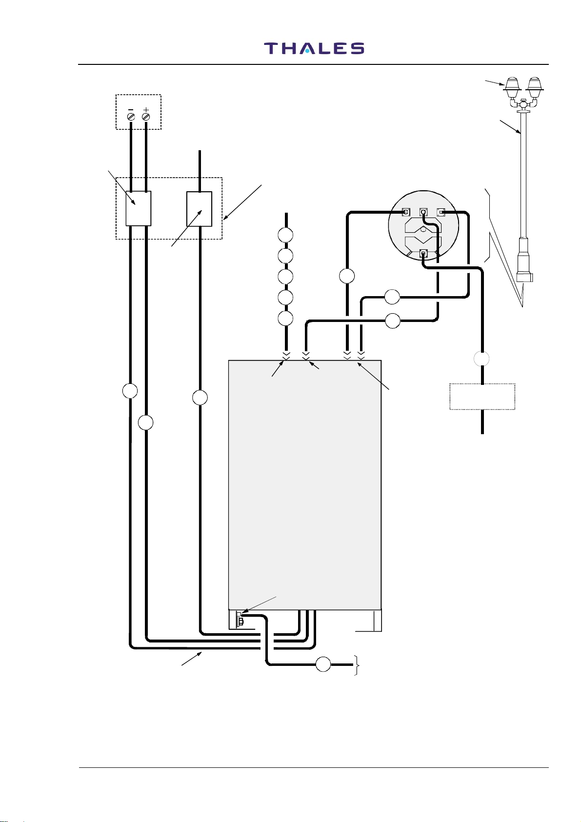
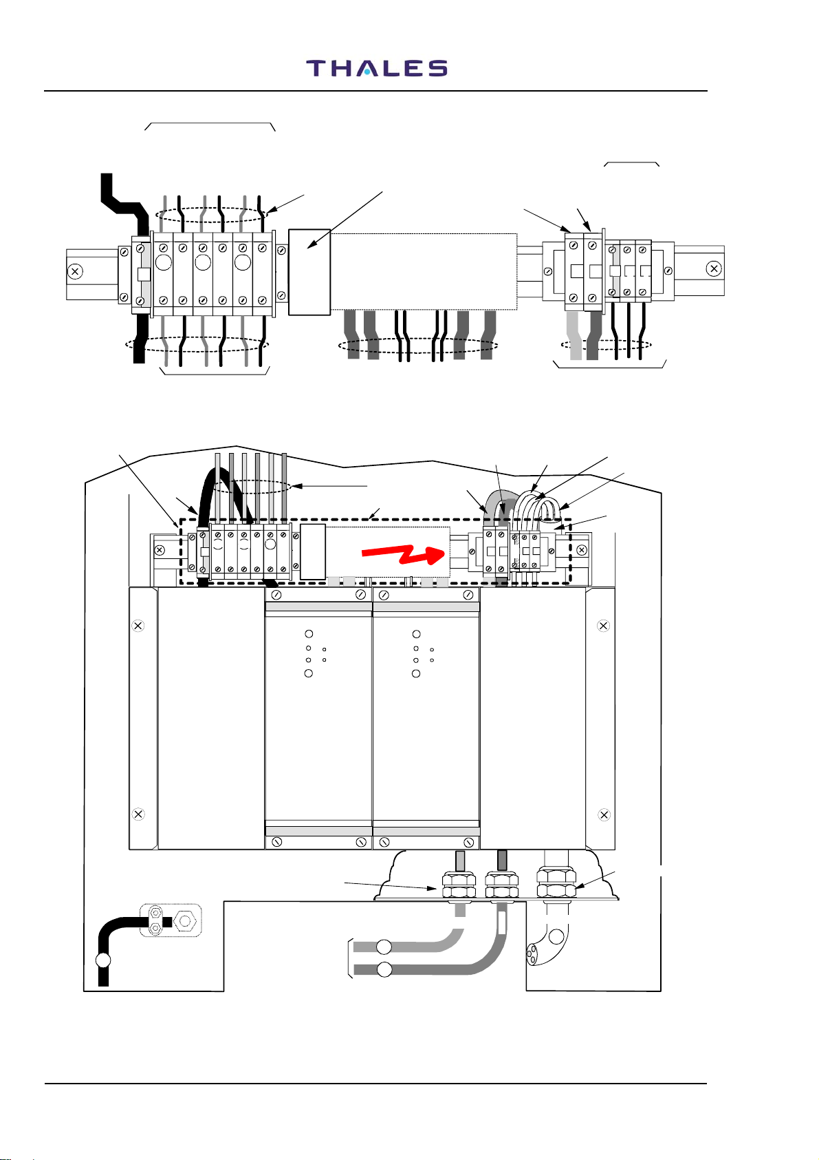
2.6 TYPICAL INSTALLATION
Figure
2.8 shows all the connections for beacon installation. Should this use an I/O system provided with the
LCSU unit in standard configuration; this figure also illustrates the characteristics of the cables used for
installation and provided by the manufacturer, as listed in table 2.1. The main characteristics of installation
cables are on figures 2.1 to 2.7. The reference item is shown on figures, internal at a circle.
Before connecting the cables check that the mains lead is dead and that the battery is not
connected (the breaker of mains and battery, on external electrical switchboard, must be OFF ).
Vers. D, September 2005
WARNING
THALES Italia S.p.A.- A. S. D.
2-3
955 900 031 C
2.6.1 Installation cables
DME 415/435 -Technical Manual
Vol. 1-Section 2 - Installation
. The main characteristics of installation cables are on figures
2.1 to 2.7. and in table 2-1.
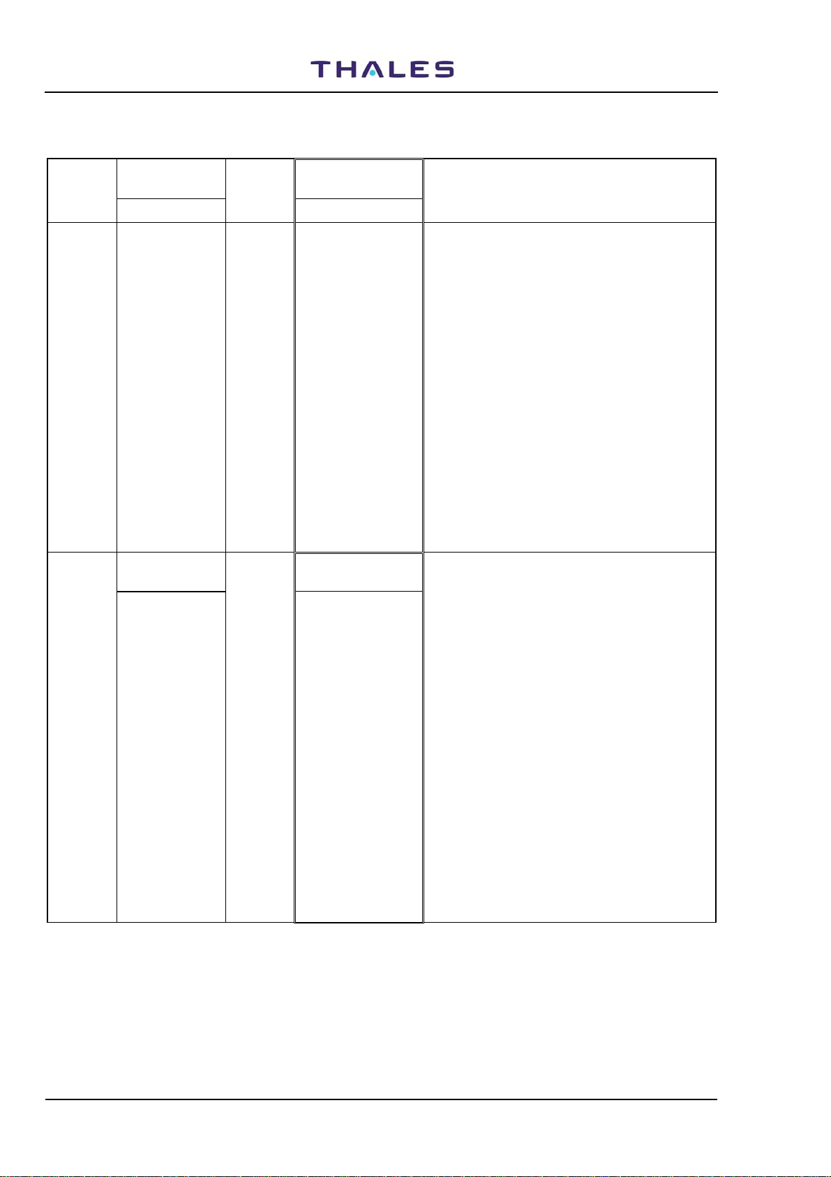
Table 2-1 - List of typical installation cables
REF. CABLE LENGTH
(m)
1 GROUND CABLE (option) 15 Single wire section:25 mm2. External wire
covering: Ø=11 mm, green/yellow color
2 MAINS POWER SUPPLY CABLE (option) 15 Three wires section 2,5mm2 each – External
cable covering Ø=15,2 mm
3 BATTERY CABLE (RO) (option) 15 Single wire section:10 mm2 -
External wire covering: Ø=7,6 mm; red color
4 BATTERY CABLE (NE) (option) 15 Single wire section:10 mm2 -
External wire covering Ø=7,6 mm; black color
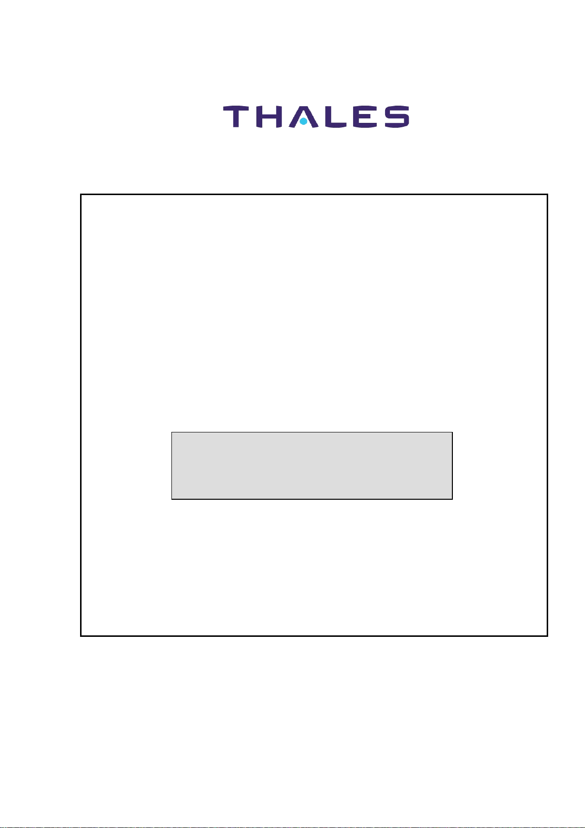
5 AUX OUT I/O CABLE (option) 10 see figure 2.1
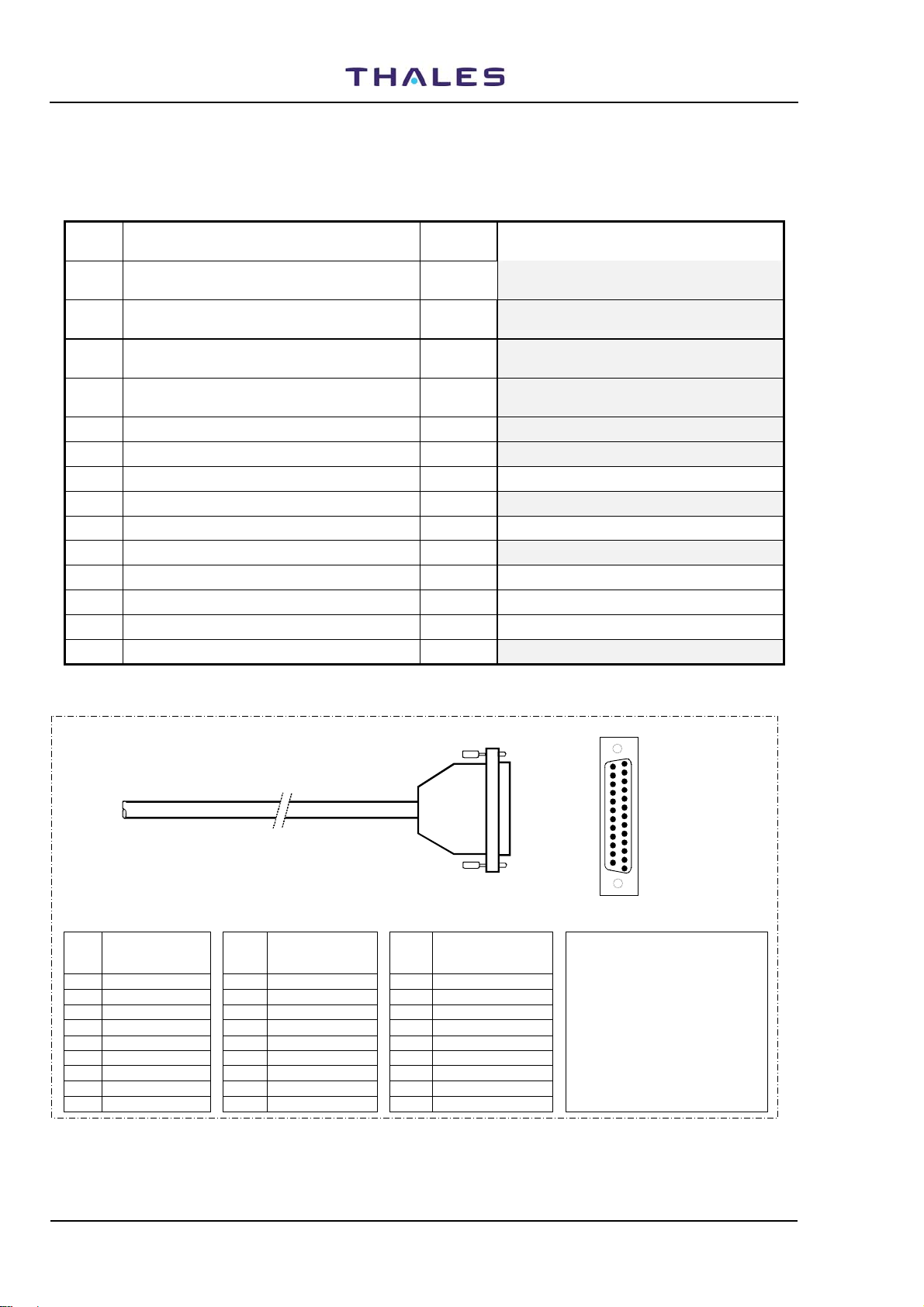
6 AUX IN I/O CABLE (option) 10 see figure 2.2
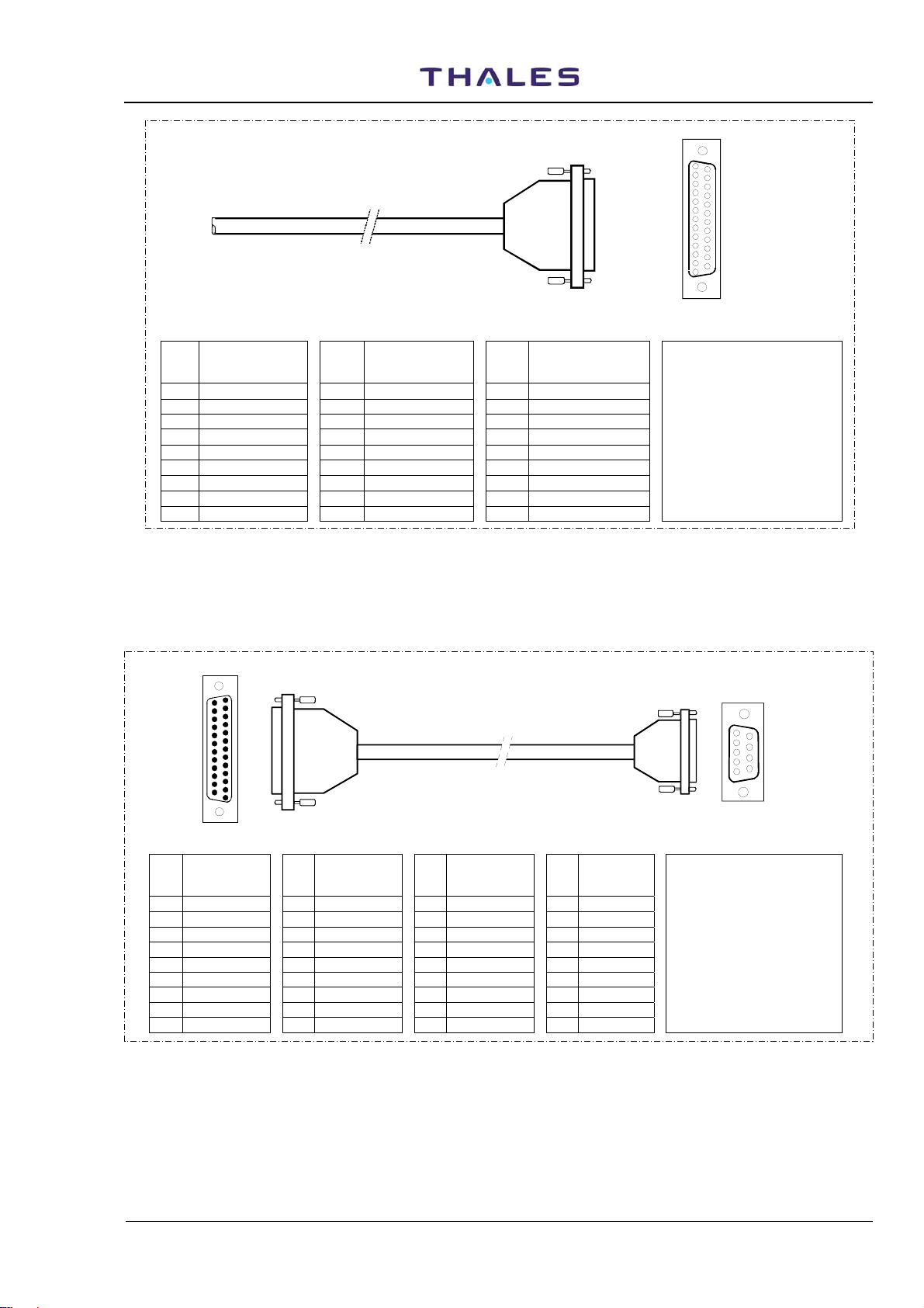
7 LOCAL PC SERIAL CABLE 3 see figure 2.3
8 RS-232 EXTERNAL MODEM CABLE (option) 3 see figure2.4
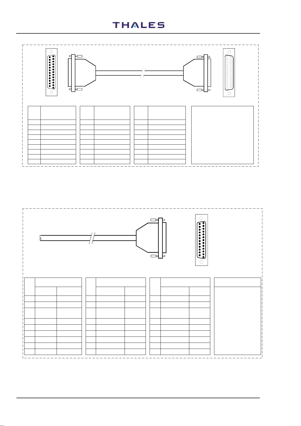
9 INTERFACE FACILITY CABLE 10 see figure 2.5
10 TELEPHONE CABLE (option) 15 Two pair twisted wire telephone cable (screened )
11 LOW LOSS ½” ANTENNA CABLE 25 see figure 2.6.
12 LOW LOSS ½” MONITOR CABLE 25 see figure 2.6.
13 LOW LOSS ½” MONITOR CABLE 25 see figure 2.6.
14 OBSTRUCTION LIGHT CABLE (option) 25 see figure 2.7 Three wire 1,5 mm2 shielded cable
NOTE
14
PL2
1
Db 25
( 25 pins
Male)
To I/O panel (SK2)
OUT Parallel port
25
pin side view
13
PIN
Wire Covering
n°
Color
1 White 10 Violet 19 WHITE/brown
2 Brown 11 Orange 20 WHITE/green n°5
3 Green bright 12 Bleu (light) 21 WHITE/yellow
4 Yellow 13 Green (dark) 22 WHITE/gray
5 Gray 14 WHITE/bleu 23 YELLOW/black see table 2-4b
6 Pink 15 WHITE/violet 24 YELLOW/red
7 Bleu (dark) 16 WHITE/red 25 YELLOW/bleu
8 Red 17 WHITE/pink
9 Black 18 WHITE/black connector cover
PIN
Wire Covering
n°
Color
PIN
Wire Covering
n°
Color
NOTE
• Reference item of table 2-1:
• Signal assignment:
• Cable screen on the
Figure 2.1. AUX OUT I/O cable
2-4
THALES Italia S.p.A.- A. S. D.
Vers. D, September 2005
DME 415/435 -Technical Manual
Vol. 1-Section 2 - Installation
955 900 031 C
1
14
SK3
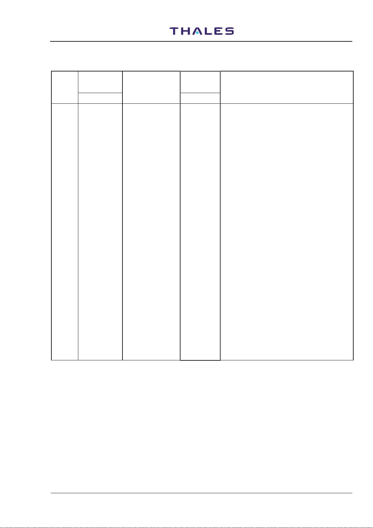
AUX IN I/O cabl e
COD. 041917 043T
To I/O panel (PL3)
IN Parallel port
13
pin side view
PIN
Wire Covering
n°
Color
1 White 10 Violet 19 WHITE/brown
2 Brown 11 Orange 20 WHITE/green n°6
3 Green bright 12 Bleu (light) 21 WHITE/yellow
4 Yellow 13 Green (dark) 22 WHITE/gray
5 Gray 14 WHITE/bleu 23 YELLOW/black see table 2-4a
6 Pink 15 WHITE/violet 24 YELLOW/red
7 Bleu (dark) 16 WHITE/red 25 YELLOW/bleu
8 Red 17 WHITE/pink connector cover
9 Black 18 WHITE/black
PIN
Wire Covering
n°
Color
PIN
Wire Covering
n°
Color
NOTE
• Reference item of table 2-1:
• Signal assignment:
• Cable screen on the
Figure 2.2. AUX IN I/O cable
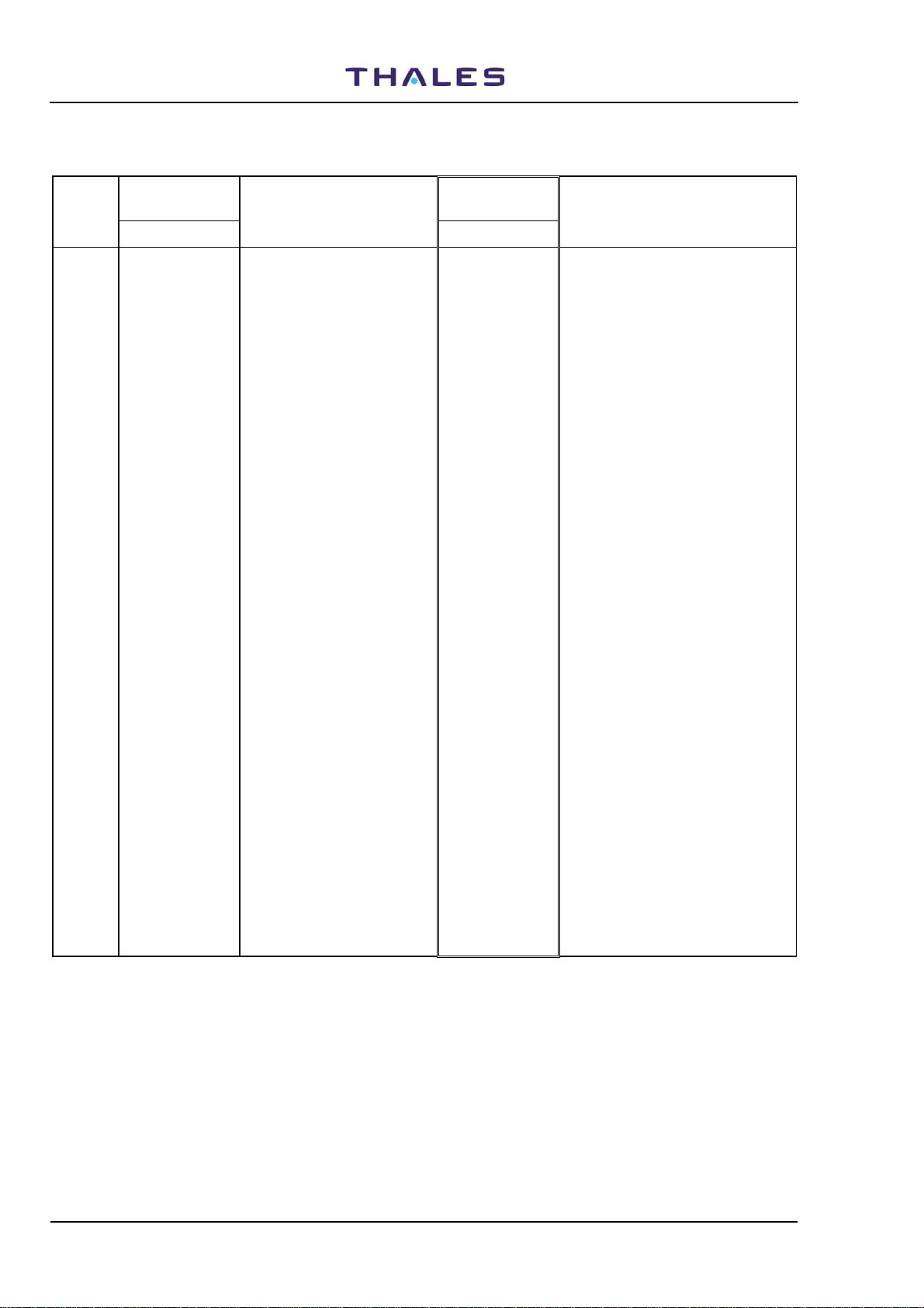
Db 25
( 25 pin s
Female)
25
14
Db 25
( 25 pins
Male)
25
pin side view
PIN
PL1 Signal
n°
assignment
1 - 10 - 19 - 1 DCD
2 RXD 11 - 20 DSR 2 RXD n°7
3 TXD 12 - 21 - 3 TXD
4 CTS 13 - 22 RI 4 DTR
5 RTS 14 - 23 - 5 GND
6 DTR 15 - 24 - 6 DSR
7 GND 16 - 25 - 7 RTS
8 DCD 17 - 8 CTS
9 - 18 - 9 RI
1
13
To I/O panel (SK1)
PC RS232 port
PIN
PL1
PL1 Signal
n°
assignment
PIN
n°
PL1 Signal
assignment
PIN
n°
typical COM1 port
PC Signal
assignm.
1
PC
5
To PC
NOTE
pin side view
• Reference item of table 2-1:
Figure 2.3. PC serial cable
Db 9
6
( 9 pins Female)
9
Vers. D, September 2005
THALES Italia S.p.A.- A. S. D.
2-5
955 900 031 C
A
A
A
W
W
W
W
Y
Y
Y
DME 415/435 -Technical Manual
Vol. 1-Section 2 - Installation
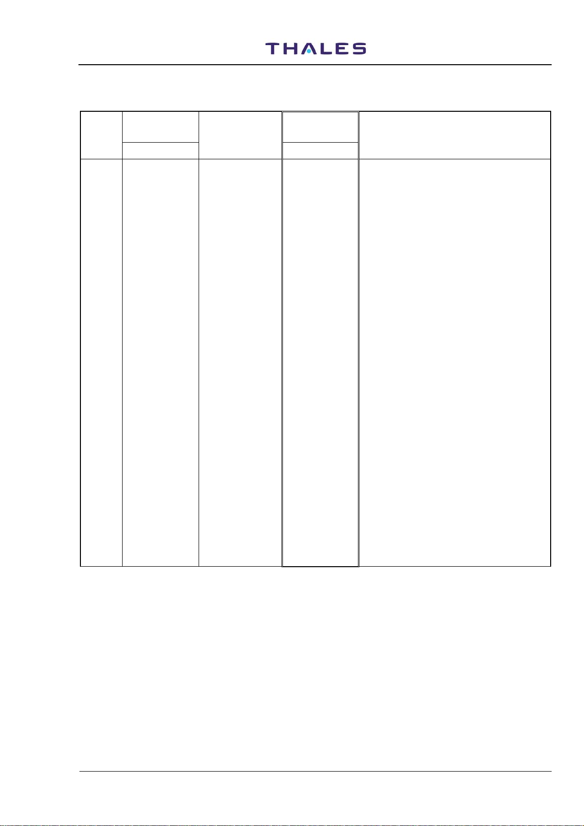
14
Db 25
( 25 pins
Male)
25
pin side view
PIN
Signal
n°
assignment
1 - 10 - 19 -
2 TXD1/2 11 - 20 DTR1/2 n°8
3 RXD1/2 12 - 21 -
4 RTS1/2 13 - 22 RI 1/2
5 CTS1/2 14 - 23 -
6 DSR 1/2 15 TXCK1/2 24 -
7 GND 16 - 25 -
8 DCD1/2 17 RXCK1/2
9 - 18 -
1
13
MDM
To MODEM
PIN
n°
Signal
assignment
PIN
n°
Signal
assignment
SK2
SK1
To I/O panel (PL1,2)
RS23 2 Serial port 3,2
NOTE
• Reference item of table 2-1:
Figure 2.4. RS232 External Modem cable
1
13
pin side view
14
Db 25
( 25 pins
Female)
25
Wire Covering Color
PIN
n°
STD
1 White Black
2 Brown White
3 Green
bright
4 Yellow Green
5 Gray Orange
6 Pink Bleu
7 Bleu (dark) White/blk
8 Red Red/black
9 Black Green/blk
lternative
Red
Wire Covering Color Wire Covering Color
PIN
n
°
10
11
12
13
14
15
16
17
18
STD
Violet Oran/blck
Orange Bleu/blk
Bleu (light) Black/whi
Green (dark) Red/white
WHITE/bleu Green/wh
WHITE/violet Bleu/whit
WHITE/red Black/red
WHITE/pink White/red
WHITE/black Oran/blk
lternative
PL4
PL5
To I/O panel (SK4,5)
Assoc. Facility EQPT
AF1,2
PIN
n°
19
HITE/brown Bleu/red
20
HITE/green Red/gre
21
HITE/yellow Oran/gre
22
HITE/gray Blk/Wh/rd
23
ELLOW/black Wh/blk/rd
24
ELLOW/red Rd/blk/wh
25
ELLOW/bleu Gr/blk/wh
STD
14
25
pin side view
lternative
1
13
Db 25
( 25 pins
Male)
NOTE
• Reference item of
table 2-1: n°9
• Signal assignment:
see table 2-6
• Cable screen on the
connector cover
Figure 2.5. Interface Facility cable
2-6
THALES Italia S.p.A.- A. S. D.
Vers. D, September 2005
DME 415/435 -Technical Manual
Vol. 1-Section 2 - Installation
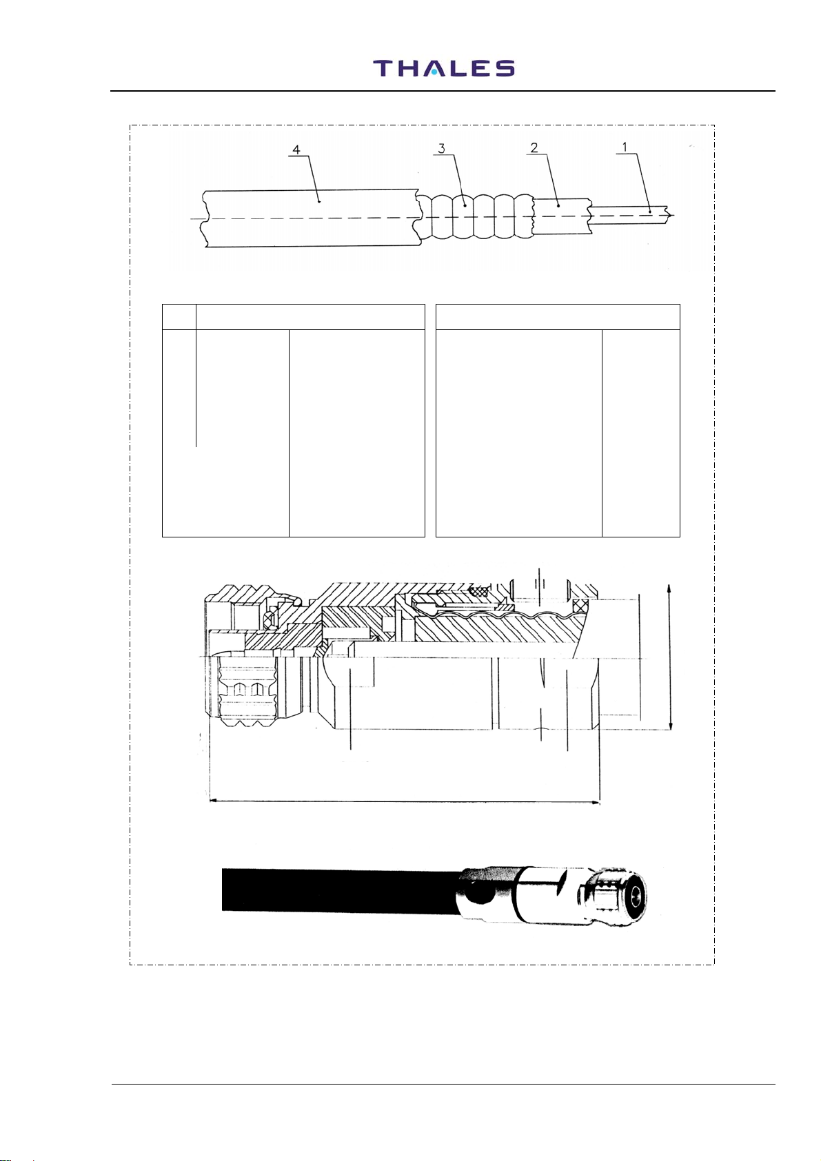
Table 2-2 - RF coax cable LCF 1/2" CU2Y type - Technical specification
item Mechanical Electrical data
955 900 031 C
1 Inner conductor Ø 4,8 mm AL/CU clad Characteristic impedance
Relative propagation velocity
2 Dielectric Ø 11,5 mm Foam PE Capacity 76 pF/m
3 Outer conductor Ø 13,8 mm corrugated
4 Jacket Ø 16,1 mm PE black Attenuation @ 20°C 0,073 dB/m
- Weight Approx. 0,23 kg/m Max operating frequency 3000 MHz
- Minimum
bending radius
copper tube
70 mm: single bending
125 mm: repeated
bending
Peak Power rating
Peak RF Voltage rating
DC-resistance inner conductor
DC-resistance outer conductor
Typical delay at 1000MHz
50 ±1Ω
88%
23 kW
1,5 kV
1,59 Ω/km
2,0 Ω/km
0.004 µs/m
Ø 21,8
reference plane
Vers. D, September 2005
SW19
58
SW19
Connector N-plug for LCF 1/2" – 50 Ω
Coax cable with connector N-plug
Figure 2.6. RF coax cable - LCF 1/2"
THALES Italia S.p.A.- A. S. D.
2-7
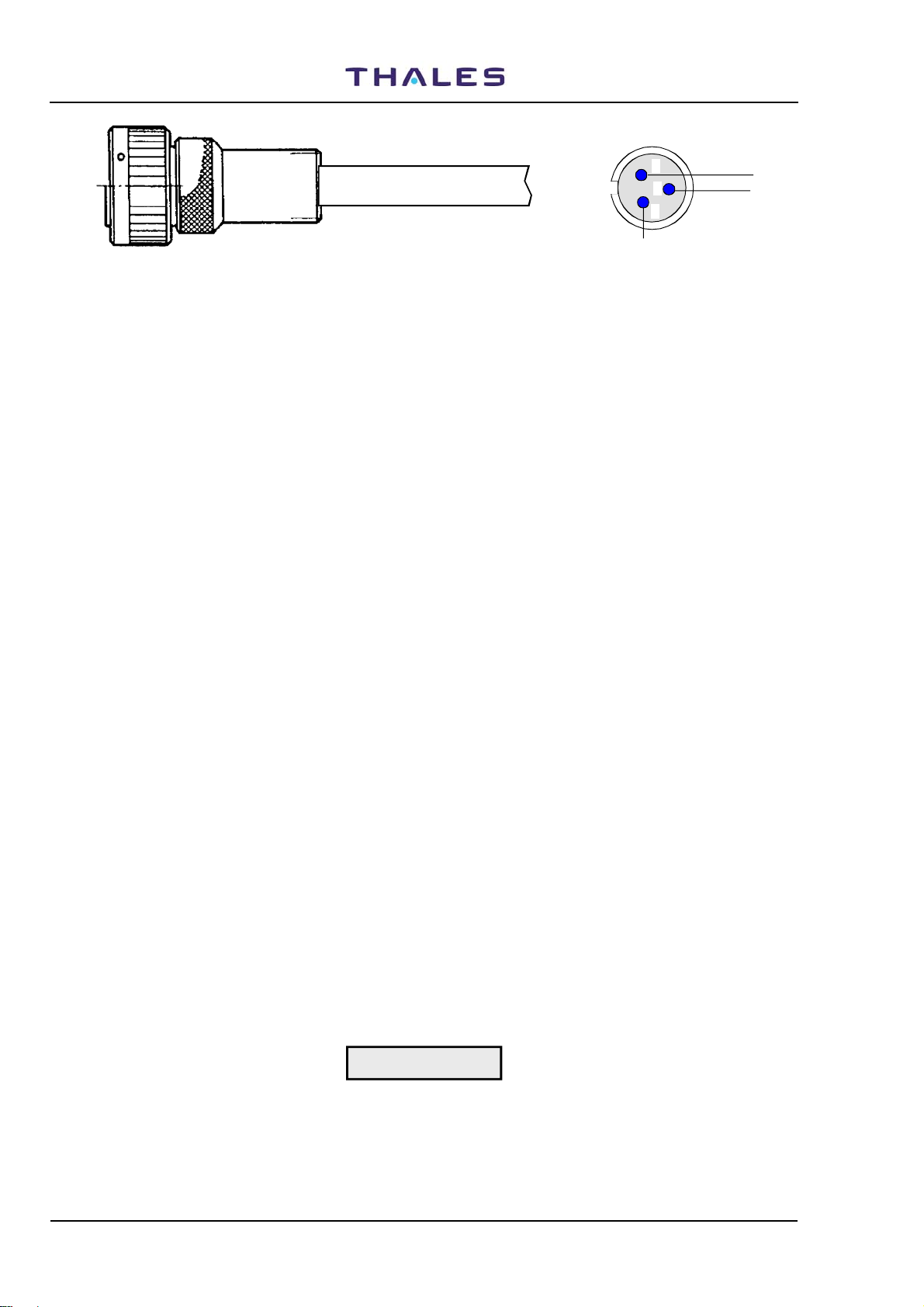
955 900 031 C
Connector: Cannon - CGL06PG 10SL-3S-C1L
3 wire shielded cabl e
DME 415/435 -Technical Manual
Vol. 1-Section 2 - Installation
pin solder rear view
A
B
C
GND
Figure 2.7. Obstruction light cable
2.6.2 Grounding
The ground cable must be laid separately and connected permanently to GND terminal of the "Terminal
Board) and to the connecting bolt of the cabinet.
A ground fault external interrupter it is suggested for a rated fault leakage current of 30 mA.
The copper cable, with cross-section 25 mm
provided for grounding the beacon. Figures
2
, and fitted with a lug for attaching to the ground bolt, is
2.10 and figure 2.12 illustrate how the beacon is grounded.
One end of the cable is inserted in the lug terminal and the other end is connected to the local ground
network, which must comply with the safety regulations stipulated in the specifications.
2.6.3 Power supply connection
The equipment can be powered from either mains, or battery, or both.
The standard version can be powered from a external 48 Vdc. The BCPS rack must be added for VAC
operation and it can either be housed inside the equipment or installed externally as well.
Cabling connections are shown in figures
2.11 and 2.12.
The BCPS unit will have a different structure depending on the type of power supply used. Furthermore,
since the beacon is not provided with any on/off breakers. It will be provided from optional breaker AC and
DC recommended with independent switch for the two power supplies.
When collocated with a System 400 (D)VOR, NDB or ILS Systems a common power supply and battery will
be implemented.
The equipment may be supplied by the mains with a 194 to 260 Vac voltage, 48 to 64 Hz, single phase, or
by an source providing a rated 48 Vdc (external source or 48Vdc battery back-up) direct power supply (40
Vdc to 60 Vdc). Equipment consumption: refer to para. 4.10.1 section 4 on this volume
Connect the mains leads (L= mains phase; N = Neutral; Mains Ground = typical green-yellow color) and
battery leads (+polarity = red cable and negative polarity = black cable) to terminals on "terminal board" as
shown in figure
2.11 or 2.13.
2-8
CAUTION
When connecting the DC supply observe the correct polarity ("+ positive" and "- negative")
THALES Italia S.p.A.- A. S. D.
Vers. D, September 2005
DME 415/435 -Technical Manual
A
Vol. 1-Section 2 - Installation
BATTERY
48Vcc
220Vac
utomatic
battery
breaker
Automatic
mains
breaker
mains
External electrical
switchboard
10
9
5
Obstr. Light
RF
M1M2INPUT
Obs. Light
12
FAN-96
ANTENNA
955 900 031 C
6
7
SK1
I/O Panel
4
3
2
see fig 2.9
Antenna
connector
13
11
Top of cabinet
Antenna
monitors probes
connectors
14
Automatic
night switch
Obstruction light
power supply
DME 400
EQUIPMENT
Ground bolt
Bottom of cabinet
Power suppl y Cables
1
To local ground network
Figure 2.8. Installation connections (typical)
Vers. D, September 2005
THALES Italia S.p.A.- A. S. D.
2-9

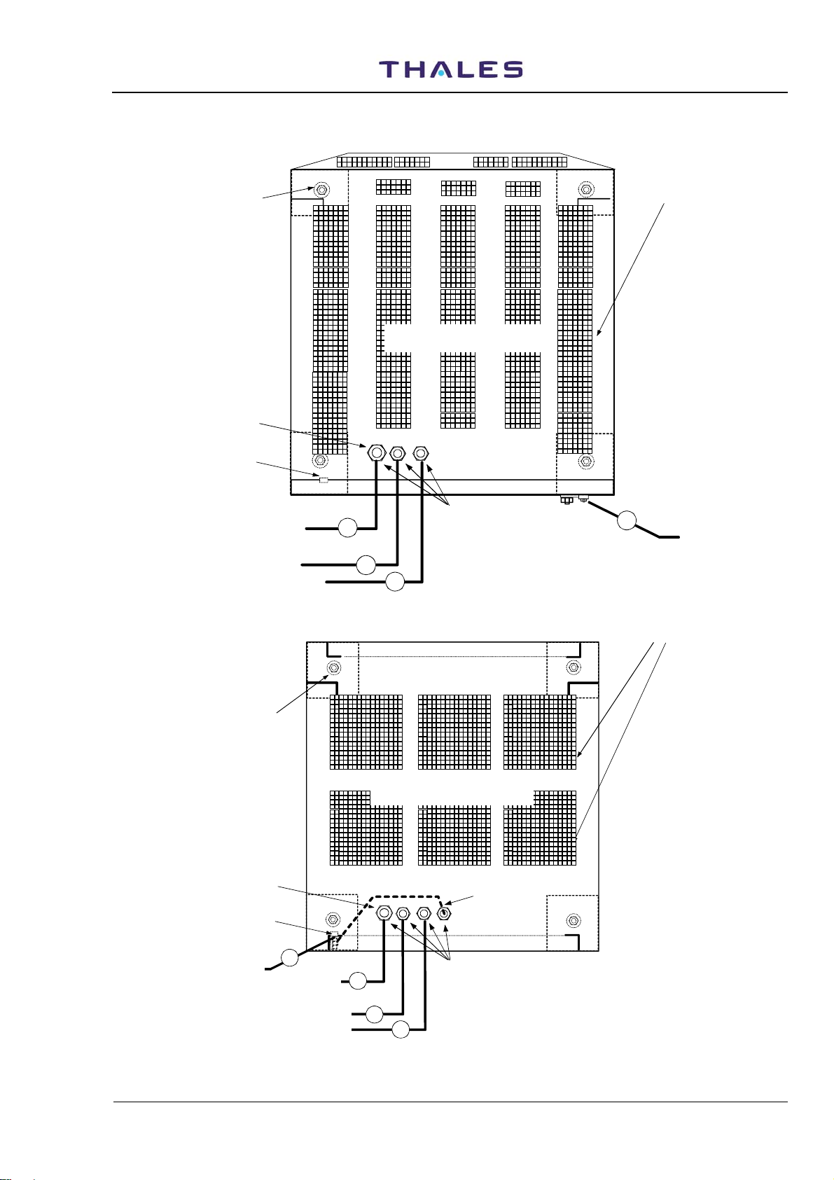
955 900 031 C
UNAVAILABLE IF
MDM1 (internal modem)
IS USED
UNAVAILABLE IF
MDM2 (internal modem)
IS USED
Rear of cabinet
DME 415/435 -Technical Manual
Vol. 1-Section 2 - Installation
To associated equipment 1
Identity Facility
N.U.
To antenna
monitors
probes
12
13
ANTENNA
MONITORS PROBES
CONNECTORS
"N" type female
Possible external
MODEM (option)
M1
M2
8
PL1
PL2
PORT 2 (DTE)
SERI AL PORT (R S 232)
AUX. IN/OUT Parallel
signals ON/OFF
PC
8
SK1
PORT 1 (DCE)PORT 3 (DCE/DTE)
PC (RS232)
OUT
7
5
SK2
OUT(0/15)
PL3
IN (0/15)
IN
6
PARALLEL PORT
SK3
OUT(16/31)
PL4
IN (16/31)
9
SK4
AF1
SK5
AF2
ASSOC. FACILITY
I/O PANEL
SK6
TACAN ANTENNA
PL7
1-6= LINE 1 3-8=LINE 2
TEL. LINES
N.U.
10
9
To telephon lines
To associated
equipment 2
Identity Facility
AIRING
GRIDS
To don't obstruct
TOP side area
N° 4 EYE
BOLTS
2-10
11
Front of cabinet
To DME antenna
ANTENNA
CONNECTOR
"N" female type
NOTE: Valid for both cabinets type
Figure 2.9. Installation - Cables connections (typical) on top end of equipment
THALES Italia S.p.A.- A. S. D.
Vers. D, September 2005
DME 415/435 -Technical Manual
Vol. 1-Section 2 - Installation
N° 4 holes
for fixing
to the plinth
Input power suppl y
cable entry
Ground bolt
Cabinet bottom view
Front door
Cabinet 297 509 007
AIRING
GRIDS
To don't obstruct
BOTTOM side area
955 900 031 C
MAINS CABLE
+ BATTERY CABLE
- BATTERY CABLE
N° 4 holes
for fixing
to the plinth
Input power sup pl y
cable en try
Bush fair-lead
2
3
4
Cabinet bottom view
Front door
Cabinet 297 509 004
Rear door
GROUND CABLE
GROUND CABLE
1
GROUND CABLE
to local GND network
AIRING
GRIDS
To don't obstruct
BOTTOM side area
GROUND CA BLE
to local GND network
Figure 2.10. Installation - Cables connections (typical) on bottom of cabinet
Vers. D, September 2005
Ground bolt
1
MAINS CABLE
+ BATTERY CABLE
- BATTERY CABLE
Bush fair-lead
2
3
4
THALES Italia S.p.A.- A. S. D.
Rear door
2-11
955 900 031 C
*to GND
local
network
48 Vdc nominal
to TRANSP. 1
-
+
++
10A
10A
DME 415/435 -Technical Manual
Vol. 1-Section 2 - Installation
TERMINAL BAR CONNECTIONS
from MAINS CABLE
Battery Depleted
Factory wired
to SERVICES
to TRANSP.2
--
2A
Breaker
I Batt. & I Nav SHUNTS
(Optional)
+ 48 Vdc input
From Battery
Battery return
(negative)
+
MAINS GND
L - MAINS LINE
N-MAINS NEUTRAL
G
N L
-
Factory wired
to BCPS back panel
from BCPS back panel
Factory wired
*) INSTALLATION CONNECTED WIRES
Figure 2.11. Cable connection - Grounding and AC power supply of the Terminal Bar
SAFETY PROTECTION
*GND
10A
Factory wired
SAFETY PROTECTION
2A
10A
-
+
-
-
+
+
Module OK
Mains OK
V adj
+
TP
-
-
AC/DC 1
WARNING
Module OK
V adj
-
Mains OK
AC/DC 2
*Battery return
*+48V ba tter y
220 Vac
+
TP
-
*Mains GND
-
+
LN
Gnd
*Mains Neutral
*Mains Phase
*Mains cable
* to local
GND network
2-12
on rear of cabinet
GND cable
1
Figure 2.12. Cables connection - Grounding and AC power supply
Bush fair-lead
*) INSTALLATION
CONNECTED WIRES
to BATTERY
THALES Italia S.p.A.- A. S. D.
3
* BATTERY cables
4
RACK BCPS
front view
Bush fair-lead
-
* Mains cable
+
2
NOTE: For cabinet 297 509 004 see fig. 2-10
Vers. D, September 2005
DME 415/435 -Technical Manual
Vol. 1-Section 2 - Installation
40 to 60 Vdc
955 900 031 C
to GND
local
network
to TRANSP. 1
to TRANSP .2
-
+
10A2A10A
to SERVICES
++
--
Factory wired
Factory wired
Battery breaker
+ 48 Vdc input
From Battery or
externa power supply
I Batt. & I Nav SHU N T S
(Optional)
Battery or 48 Vdc
return (negative)
Factory wired
Not Used
N-MAINS
NEUTRAL
MAINS
GND
G
+
-
N L
L - MAINS
LINE
Figure 2.13. Grounding and external 48 Vdc power supply - Cables connection
2.6.3.1 Batteries
The battery of back up is used in case of blackout, to allow the beacon to keep working without interruption.
cavo positivo
Terminali dei cavi
cavo negativo
Batteri a 12 V/ 5 0A / h
+
-
Batteria 12V/50A /h
+
Batteria 12V/50A /h
+
cavi di
connessione
-
Batteria 12V/50A /h
+
Tensione centrale
Figure 2.14. Battery connections typical
Battery type and size depend on requirements.
Suggested batteries for back-up power supply must have the following characteristics:
- Output voltage: 48 V nominal (four 12 V unit serially connected: see fig.
2.14);
- Nominal discharge capacity: 50 A/h (this capacity ensures a time duration as at para. 4.10 of section 4);
- Low maintenance types or sealed types;
- Low self-discharge;
- Long life: >4 to 5 years;
- Temperature range: -20 to +50 °C;
- The charge from the equipment, at constant voltage, is typically: 2.25 V/element.
These required characteristics should be completed by technical information from the battery constructor.
CAUTION
The low maintenance battery group must be placed in a low-ventilated
environment, while the other sealed types, may be installed everywhere. In any
case, follow the battery constructor’s instructions.
2.6.3.1.1 Battery duration time (on 230Vac black-out)
The battery 50A/h (at end of 42V voltage), are the following:
DME415=20h - DME435=12h for TX2 stby, TX1 en service, and radiate 800 pps
DME415=18h - DME435=10h for TX2 stby, TX1 en service, and radiate 2700 pps
DME415=17h - DME435=7h pour TX2 stby, TX1 en service and radiate 4800 pps
NOTE: With battery 12 mounts old the back up period duration is typical degraded of 10/15% (see also
the technical information from the battery constructor)
Vers. D, September 2005
THALES Italia S.p.A.- A. S. D.
2-13
955 900 031 C
DME 415/435 -Technical Manual
Vol. 1-Section 2 - Installation
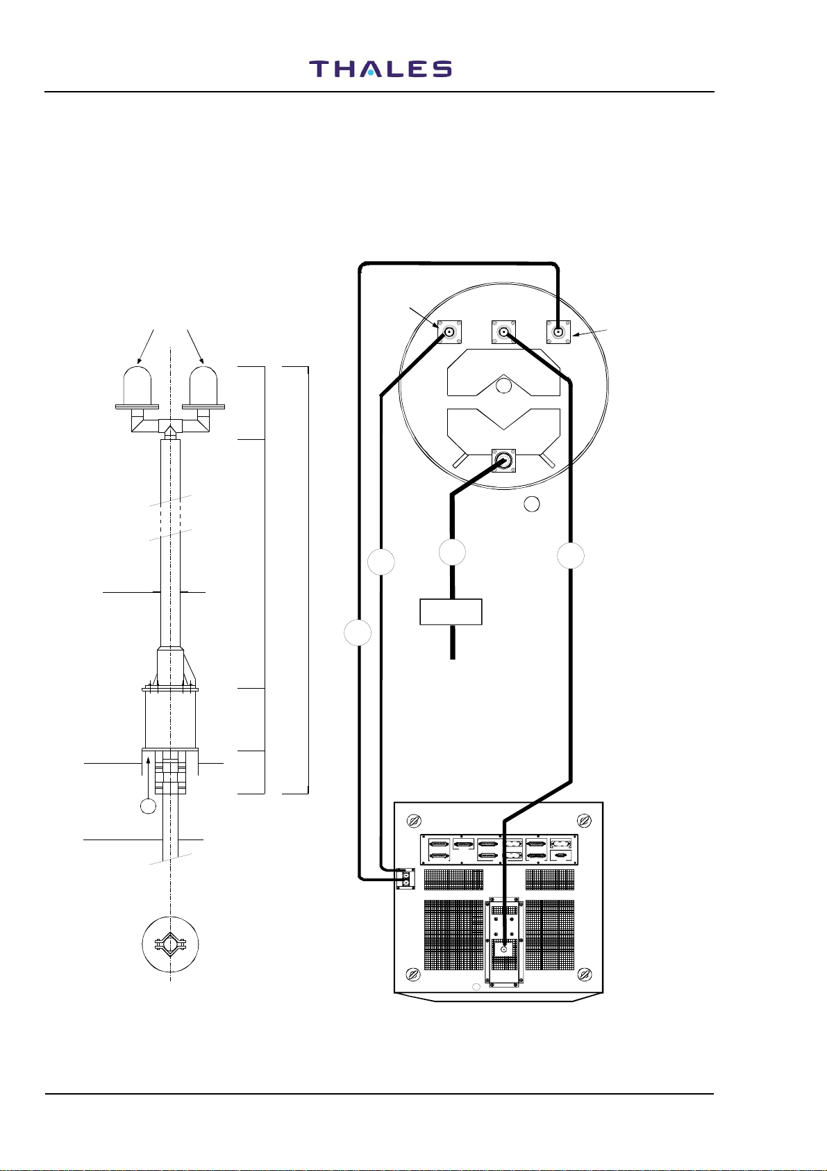
2.6.4 ANTENNA CONNECTION
Mechanical antenna collocation is simple and straightforward with any type of existing VOR, DVOR or ILS
antenna.
Figure
2.15 shows the connections to be performed upon antenna installation and the identification of the
cables supplied.
Characteristics and dimensions: see para. 4.9 on section 4 of this volume (FAN 96 type dimensions are in
2.15)
figure
Antenna probe
Obstructions light
MONITOR 1
connector
~3502200
Connettore
d'ANTENNA
OL
M2M1
Antenna probe
MONITOR 2
connector
90
220
60.5 max
12
View from
14
A
11
3050
Daylight
sensor
13
Obstruction light
power supply
300200
A
ASSOC. FAC ILITY
SK6
SK4
TACAN ANTENNA
AF2
PL7
SK5
1-6= LINE 1 3-8=LINE 2
AF1
TEL. LINES
PL1
PORT 1 (D CE)PORT 3 ( DCE/DTE)
PC (RS232)
PL2
PORT 2 (D TE)
SERIAL PORT (RS23 2)
M1
M2
OUT(16/31)
OUT(0/15)
PL4
PL3
IN (0/15)
IN (1 6/31)
PARALLEL PORT
SK3
SK2
SK1
2-14
11
Cabinet top view
Figure 2.15. Cable connections to FAN 96 antenna
THALES Italia S.p.A.- A. S. D.
ANTENNA
CONNECTOR
"N" female typ e
Vers. D, September 2005
DME 415/435 -Technical Manual
× = Δ
Vol. 1-Section 2 - Installation
955 900 031 C
2.6.4.1 Antenna coax cables-Attenuations and delays
The interrogating signal from the aircraft received on the beacon antenna, comes the antenna connector
SK1 (equipment input/output RF) with a delay Δt
which depends on the antenna coax cable.
RF
This delay, indicated in μs, is given through the following relation:
L
P
c
t
RF
where:
- L: Cable length expressed in m
- P: Relative propagation velocity (for LCF 1/2" cable, typical value: 88%)
- c: Light velocity (300 m/μs)
The low loss "LCF 1/2 inch" standard cable, has a delay of about 0.004 μs/m and an attenuation of about 0.073 dB/m.
The signal received in antenna comes the beacon receiver after a ΔtRF delay, is processed and, after the
reply delay (introduced by the transponder), returns to the antenna from where it is transmitted with an
additional delay Δt
(introduced by the antenna coax cable). If it is supposed that the beacon uses a "X"
RF
channel mode (50 μs reply delay), the total delay of the reply signal, generated by the antenna output
system, will be:
Rvel. = Δt
+ 50 μs + Δt
RF
= 2Δt
RF
+ 50 μs
RF
The measurement of the reply delay value and its automatic compensation, in 25ns steps compared to the
fixed value, is performed by the monitors through interrogating pulses (Pilot pulse) sent by the transponder
receiver.
The calculated value of the delay and the cables loss according to their length is shown as an example in
the following table
2-3):
Table 2-3 - STD Coax cables
Coax. cable
Parameter Description
Monitor Cable Loss Loss of monitor coax. cables probes
Type Length
LCF 1/2" 25 m Approx. 2dB
Value
for monitoring
Antenna Cable Loss Loss of antenna coax. cable LCF 1/2" 25 m Approx. 2dB
Delay time Delay of antenna coax. cable LCF 1/2" 25 m Approx. 100 ns
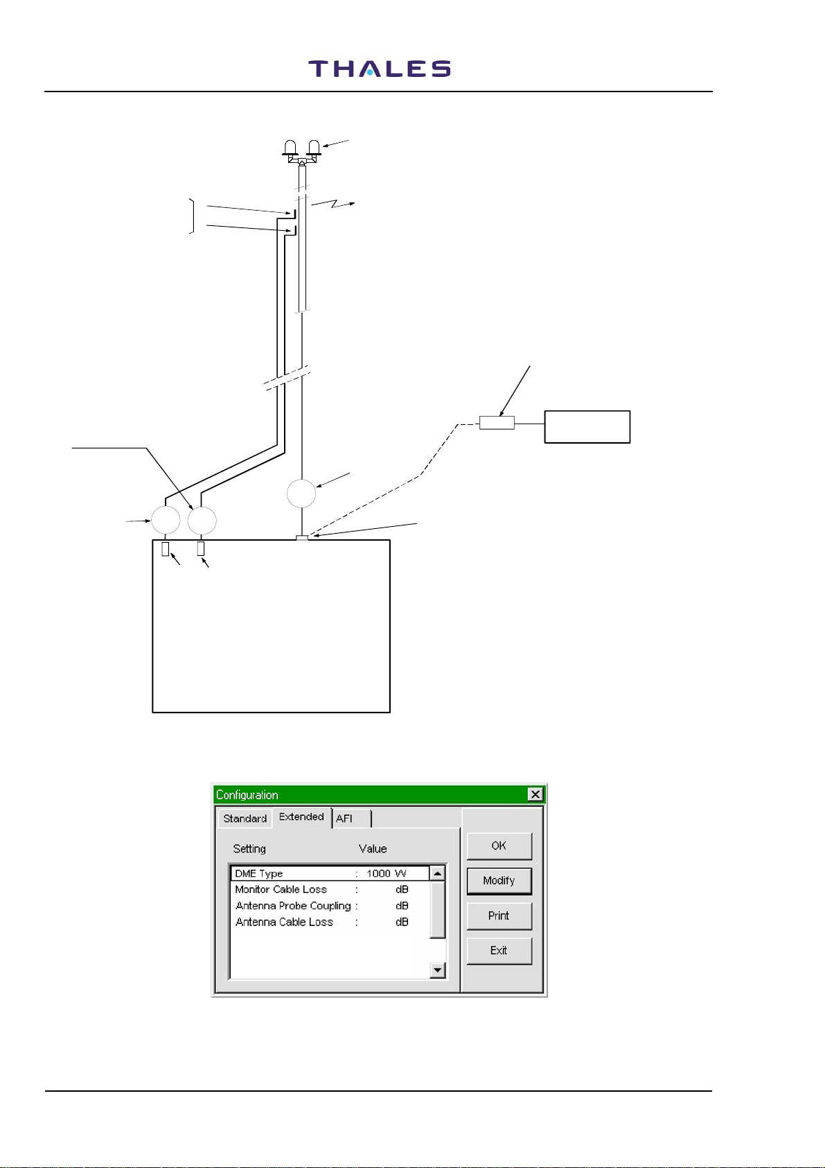
2.6.4.2 Data entry calibration procedure for “EXTENDED CONFIGURATION”
Figure
2.16a) shows an example of typical installation with equipped standard cables.
For calibration and check of the correctness of the power parameters measurement displayed on windows
of the “CHECK”, preset the configuration “EXTENDED CONFIGURATION” (fig.
2.16b) with the procedures
here below (also see in this volume, Appendix “D” PC user EQPT Manager on paragraphs: "Executive
Monitoring on Antenna", "STD measurements & Routine Check on Antenna" and "UTILITY – DME
Configuration").
Remark: The peak power output calibration procedure of the TX100 ad TKW modules is described on
section 5 -MAINTENANCE- para. 5.3.4 and 5.3.5 of this volume. This procedure must be carried
out during the installation, in the event of substitution of module TX100 or/and TKW and also in
case the channel change.
Vers. D, September 2005
THALES Italia S.p.A.- A. S. D.
2-15
955 900 031 C
Obstruction lights
DME 415/435 -Technical Manual
Vol. 1-Section 2 - Installation
Monitoring Antenna
couplers (internal to
antenna)
Monitor 1 probe cable
Monitor 2
probe cable
13
(only for DME 435)
1
2
12
10 dB PAD
DME EQPT
Antenna cable
11
SK1
Transm itte d Po we r
Peak Power Output
Typical values (coax. cable LCF 1/2", 25 m lenght):
Monitoring Antenna couplers :
(for FAN96 antenna)
Monitors cables loss : 2 dB
Antenna cable loss : 2 dB
PAD
Power meter
protection
attenuator
Peak Power
meter
21dB ± 3dB
2-16
Figure
Figure 2.16a. Simplified diagram of Antenna coax cables
2.0
21.5
2.0
Mon. 1 Power Adj. : +50
Mon. 2 Power Adj. : -10
Mains Power Supply : Frako
2.16b. “EXTENDED CONFIGURATION” – Example of data entry
THALES Italia S.p.A.- A. S. D.
Vers. D, September 2005
DME 415/435 -Technical Manual
Vol. 1-Section 2 - Installation
955 900 031 C
2.6.4.2.1 Check of the OUTPUT POWER measurement on transponder
a) Preset the equipment in "Maintenance" mode (TX in STBY). Unplug the antenna cable and to connect
the "peak power meter", as in fig.
2.16a, to the antenna connector. Switch to “OPERATING” mode, take
notes of the reading of the power peak meter.
b) Restore the connections of the antenna cables. With TX main in OPERATING and on window
“EXTENDED CONFIGURATION – Mon. 1 Power Adj.” Enter, if necessary, a preset value from -100,
99, -98 ......to .....+98,+99,+100 (Nr. 1 step by step), in order for the measurement reading on
“Executive monitoring: Peak Power Output” to be the same (±2%) as the one indicated on the external
“Peak Power Meter”, previously noted.
c) Repeat point b) for “Mon. 2 Power Adj." on window “EXTENDED CONFIGURATION
2.6.4.2.2 Measurement calibration of the TRANSMITTED POWER (radiated)
a) TX main on antenna in OPERATING. On window “EXTENDED CONFIGURATION – Monitor Cable
loss” enter the value, measured or calculated, of the monitor probe cable loss (for standard cable see
table in previous para.
2.6.4.1)
b) On “EXTENDED CONFIGURATION – Monitor Probe Coupling” enter the value of the coupler at the
operating frequency, a detail that is pointed out on the antenna features. For the model FAN 96 and
FAN 88 the coupling values of the probes are shown on a table enclosed to the package of the antenna
(for antenna FAN 96: typical value 20dB ± 3dB)
c) On “EXTENDED CONFIGURATION – Antenna cable loss” enter the value, measured or calculated, of
the antenna cable loss (for standard cable see table in previous para.
2.6.4.1)
d) The measure indicated in “Transmitted Power”, in theory, should be:
[“Peak Power Output” – Antenna cable loss] in Watt
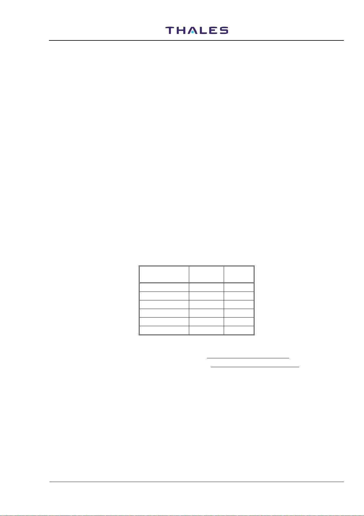
Some significant power ratios and loss percentage are calculated as per the following table
2-4 :
Table 2-4 - Loss of STD coax cables
Ant. cable loss:
dB
Ratio
Loss
%
-3 0,5 50
-2 0,63 37
-1,5 0,708 29,2
-1 0,78 22
-0,5 0,89 11
-0,1 0,9772 2,28
Example: with STD cable (25m – LCF ½”) the reading in “Transmitted Power” must be:
1) for DME 415 with 110 W in Peak Power Output: 110 – (110 * 0,347) = 71,83 W
2) for DME 435 with 1050 W in Peak Power Output: 1050 – (1050 * 0,347) = 685.6 W
e) if the reading in “Transmitted Power” is over ± 2% compared to the value mentioned in point d), vary,
step by 0,1dB step , the data on window “EXTENDED CONFIGURATION – Monitor Probe Coupling”
(or in “Monitor cable loss”) up to the limit of ± 2%.
NOTE 1: The sum of the values in dB [Monitor Cable Loss + Antenna Probe Coupling + Antenna
Cable Loss] must be >20 dB and <33 dB, otherwise the data will refused.
NOTE 2: Values in “Transmitted Power” of each monitor can be adjusted within ±10%.
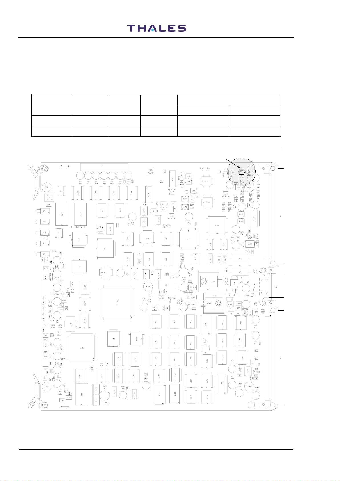
Difference of measure of the values in "Transmitted Power" between the two monitors due to
different attenuations of the coaxial cables, couplers and internal coax cabling, can be
corrected with the trimmer P6 mounted on module MON (shown in fig.
monitor to read measurements that are as equivalent as possible.
Vers. D, September 2005
THALES Italia S.p.A.- A. S. D.
2.17), in order for each
2-17
955 900 031 C
DME 415/435 -Technical Manual
Vol. 1-Section 2 - Installation
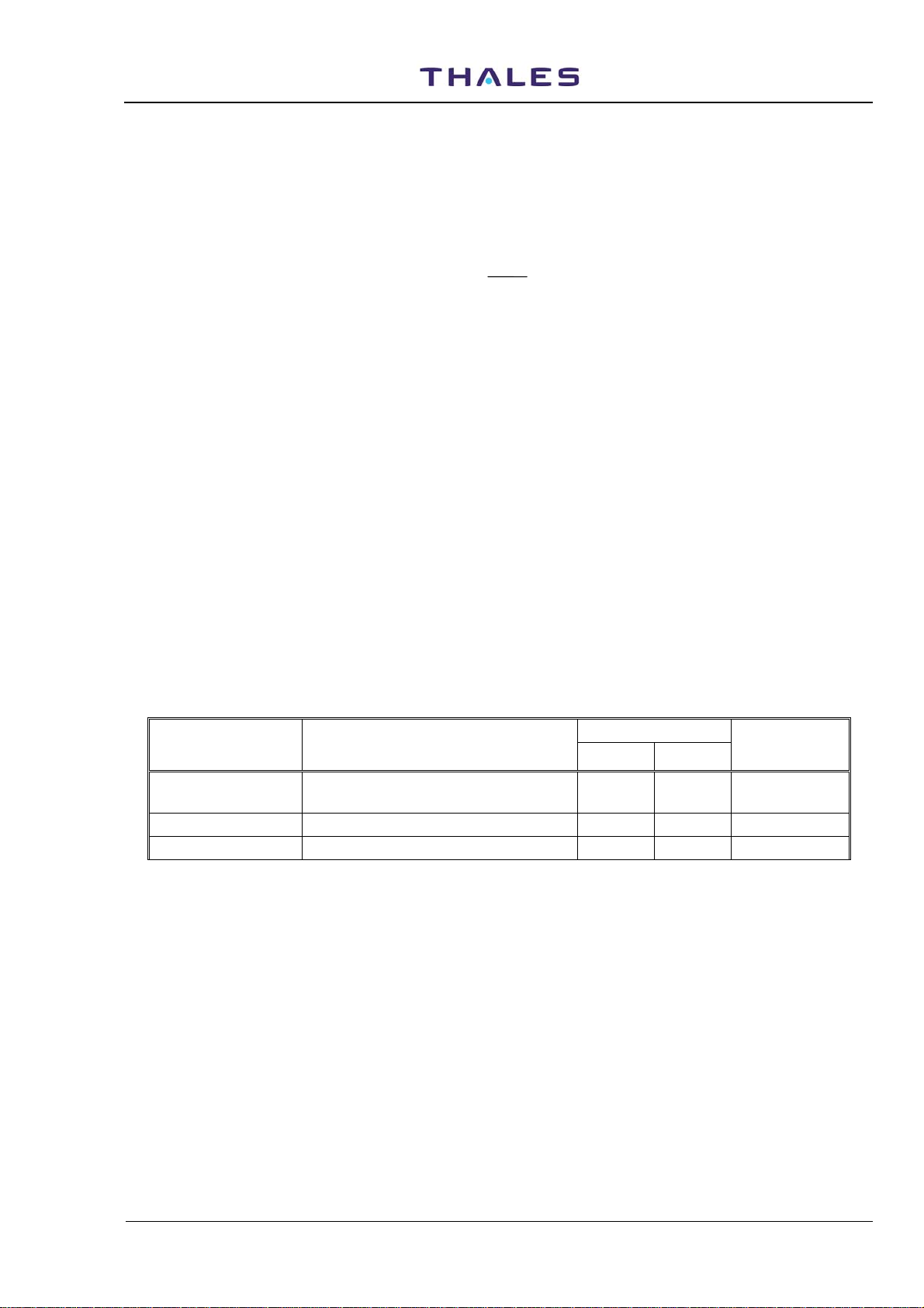
f) The power alarm thresholds of the monitors are programmed for fixed ratios, as data "SETTING" preset
and the monitors also, automatically counts the loss of the coax cables predisposed in "Extended
Configuration".
Examples are shown in table
2-5) for standard cables and with data "SETTING" of monitors power
alarm preset = -3dB:
Table 2-5 - Monitors power alarm threshold examples
EQPT Peak power
Ant. Cable
output
loss
Transmitted
power
Monitors Power Alarm threshold
Peak Power out Transmitt. power
DME AN 415 120 Wp -1,85 dB 78 Wp 60 Wp 39 Wp
DME AN 435 1050 Wp -1,85 dB 686 Wp 525 Wp 343 Wp
Measu re of TR AN S MITTED POWE R - Cal ibr. adj. tri m m er
Figure 2.17. MON module – Trimmer adj. position of the “Transmitted Power” measurement
2-18
THALES Italia S.p.A.- A. S. D.
Vers. D, September 2005

DME 415/435 -Technical Manual
Vol. 1-Section 2 - Installation
2.6.5 Adjustment Power Reading by monitor
955 900 031 C
Reply Delay
Reply efficiency
Pulse spacing
Peak Power Output
Transmission Rate
Transmitter Freq.
Transmitted Power
Reply Delay
50,01
98
12.00
1062
805
1020.0
1001
µs
%
µs
Watt
ppps
MHz
Watt
Figure 2.18 Screen of correct measurement by Monitor 1 & 2
To adjust value of Peak Power Output (see figure
- MON1 Power Adj
- MON2 Power Adj
The range value is from –100 to +100. See figure
50,00
µs
%
96
µs
12.00
1065
Watt
ppps
805
MHz
1020.0
Watt
1000
2.18) you have to change the following value of preset:
2.19.
Figure 2.19 Screen of configuration for power reading adjustment
To adjust value of Transmitted Power for both monitors, you have to change the values of preset. See
2.19
figure
- Monitor Cable Loss
- Antenna Probe Coupling
There is also a possibility to adjust value of power for each monitor, so you can align monitor1 with monitor2
by TRIMMER P6 on monitor board.
NOTE: Be careful !!!! Don’t touch any other TRIMMER on monitor board
Remark: The peak power output calibration procedure of the TX100 ad TKW modules is described on
section 5 -MAINTENANCE- para. 5.3.4 and 5.3.5 of this volume.
Vers. D, September 2005
THALES Italia S.p.A.- A. S. D.
2-19

955 900 031 C
DME 415/435 -Technical Manual
Vol. 1-Section 2 - Installation
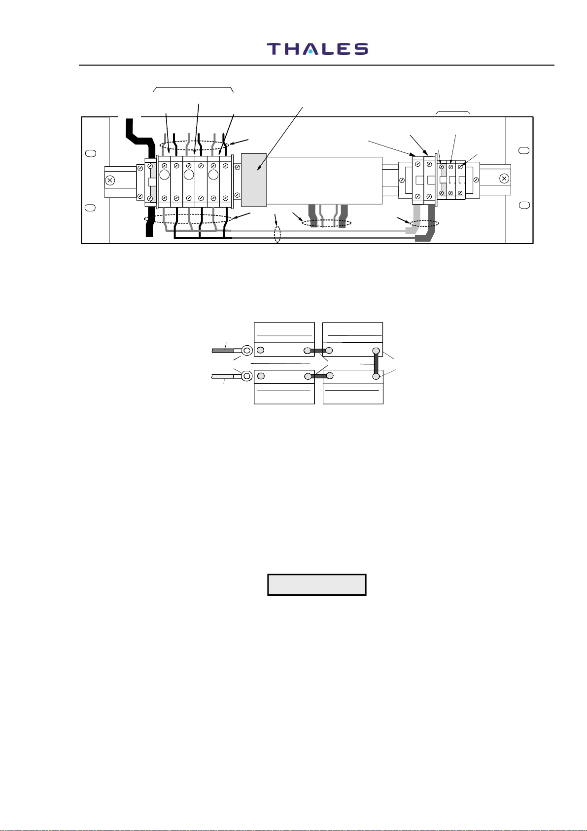
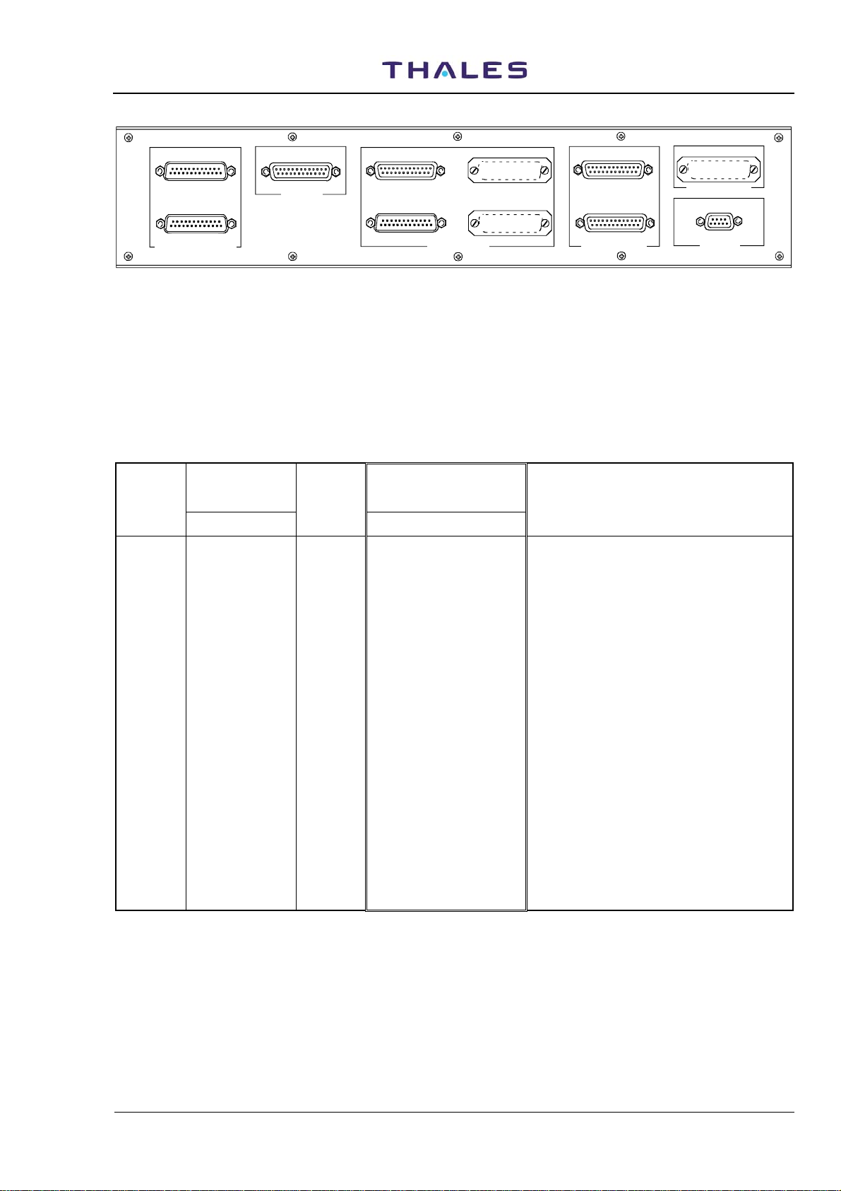
2.6.6 I/O and external interface connections
The following I/O connectors (figure 2.15) are available on the top of the cabinet:
• PL1 - SERIAL PORT 3 (standard DTE) – 25 pin Sub D male connector
• PL2 - SERIAL PORT 2 (DTE) – 25 pin Sub D male connector
• SK1 - PC local operation (reciprocally exclusive to SK1 front panel LCSU) – 25 pin Sub D female
connector
• SK2 - PARALLEL PORT n° 16 out ON/OFF solid state relay lines – 25 pin Sub D female connector
• PL3 - PARALLEL PORT n° 16 in ON/OFF optocoupled lines – 25 pin Sub D male connector
• SK3 - N.U.
• PL4 - N.U.
• SK4 - ASSOCIATED FACILITY (AF1) interface – 25 pin Sub D female connector
• SK5 - ASSOCIATED FACILITY (AF2) interface – 25 pin Sub D female connector
• PL7 - Telephone lines PSTN or dedicated line connection -9 pin Sub D male connector
Figure
2.9 shows all the connections on I/O panel and figure 2.20 shows the connectors of I/O panel on top
end of cabinet.
Tables
signals. On table
2-6a) and 2-6b , (serial ports) and tables 2-7a ,b,c,d (parallel ports), list the pin-out connector
2-8 and table 2-9 are listed the pin-out of the connectors of the telephone line and
Associated.
Figure
2.21 shows typical examples of electrical connections related to parallel input lines, user
configurable, for the PL3 connector - PARALLEL IN - of the I/O panel.
The block a) shows the drive connection with the contact to ground of the input signal on Nr. 8 lines. The
blocks b) and c) show the possibility to drive separately, every input line of the allowable ones (eight). Every
line can be driven with a high or low level signal which configurable links (M49, M50, M51, M52) as shown in
2.23 .
figure
On table,
Typical examples of how to use the parallel OUTPUT lines are shown in figure
2-7a is shown the parallel input line used by equipment for flag indication of AC/DC power supply
2.22 where:
− in block b) a single line external connection for a configuration with a distinct common is shown;
− in block c) a four lines connection with only a user power supply (Vg) is shown;
− in block d) a four lines connection with a distinct power supply is shown;
− in block e) a solution with a power supply (5VDC), picked up from the pin 25 of SK2 connector of the
I/O panel is shown.
The commons are arranged in four lines groups, as shown in table
2-7b and in figure 2.22.
2-20
THALES Italia S.p.A.- A. S. D.
Vers. D, September 2005
DME 415/435 -Technical Manual
Vol. 1-Section 2 - Installation
955 900 031 C
PL1
PL2
PORT 2 (DTE)
SERIAL PORT (RS232)
PL1 = UNAVAILABLE if MDM 2 IS USED
PL2 = UNAVAILABLE if MDM 1 IS USED
SK1 = PC connection:
connector on FRONT PANEL is USED
SK4 = Associated Faci lit y EQPT 1
SK5 = Associated Faci lit y EQPT 2
UNAVAILABLE if PC
SK1
PORT 1 (DCE)PORT 3 (DCE/DTE)
PC (RS232)
SK2
OUT(0/15)
PL3
IN (0/15)
PARALLEL PORT
SK2 = N° 16 AUXILIARY ON/OFF OUT SIGNALS (standard)
PL3 = N° 16 AUXILIARY ON/OFF IN SIGNALS (standard)
(e.g. possible Site Status Indication)
SK3 = N° 16 AUXILIARY ON/OFF OUT SIGNALS (optional)
PL4 = N° 16 AUXILIARY ON/OFF IN SIGNALS (optional)
SK3
OUT(16/31)
PL4
IN (16/31)
SK4
AF1
SK5
AF2
ASSOC. FACILITY
TACAN ANTENNA
1-6= LINE 1 3-8=LINE 2
TEL. LINES
SK6 = N.U.
PL7 = N° 2 Telephon Line
Internal MODEM connected
Figure 2.20. I/O panel, top view
Table 2-6a - SK1 on I/O panel and front panel - Serial Ports PC connector pin-out signals
SIGNAL
CONNECTOR ON
CSB MODULE
M22-PIN Nr.
SERIAL
DCE
Port Nr.
(Spare) 1 1
(Spare) 2 - 14
RXD 3 1 2
(Spare) 4 - 15
TXD 5 1 3
(Spare) 6 16
CTS∼
7 1 4
(Spare) 8 17
RTS∼
9 1 5
(Spare) 10 18
(Spare) 11 6
(Spare) 12 19
GND 13 1 7
DCD∼
DTR∼
14 1 20
15 1 8
(Spare) 16 21*) *) pin from 9 to 13 and 22 to 25: N.U.
PC CONNECTOR on I/O
PANEL
and on LCSU Front panel
PC-SK1- PIN Nr
NOTE
SK6
PL7
Vers. D, September 2005
THALES Italia S.p.A.- A. S. D.
2-21
955 900 031 C
Table 2-6b - PL1 and PL2 on I/O panel - Serial Ports MDM connector pin-out signals
DME 415/435 -Technical Manual
Vol. 1-Section 2 - Installation
SIGNAL
CONNECTOR ON
CSB MODULE
M22-PIN Nr.
SERIAL
DTE
Port Nr.
CONNECTOR on I/O
PANEL
MDM1-PL2 -PIN Nr
NOTE
(Spare) 17 1
(Spare) 18 14
TXD1 19 2 2
TXCK1 20 2 15
RXD1 21 2 3
(Spare) 22 16
RTS∼1
23 2 4
RXCK1 24 2 17
CTS∼1
25 2 5
(Spare) 26 18
DSR1-386 27 6
(Spare) 28 19
PGND 29 2 7
DTR∼1
DCD∼1
30 2 20
31
2
8
(Spare) 32 21*) *) pin from 9 to 13 and 22 to 25: N.U.
M22-PIN Nr
MDM2-PL1- PIN Nr
(Spare) 33 1
(Spare) 34 14
TXD2 35 3 2
TXCK2 36 3 15
RXD2 37 3 3
(Spare) 38 16
RTS∼2
39 3 4
RXCK2 40 3 17
CTS∼2
41 3 5
(Spare) 42 18
DSR2-386 43 6
(Spare) 44 19
PGND 45 3 7
DTR∼2
DCD∼2
46 3 20
47
3
8
(Spare) 48 21*) *) pin from 9 to 13 and 22 to 25: N.U.
Pin 49 to 64 on M22 (CSB) : N.A.
2-22
THALES Italia S.p.A.- A. S. D.
Vers. D, September 2005
DME 415/435 -Technical Manual
Vol. 1-Section 2 - Installation
Table 2-7a - PL3 on I/O panel - INPUT Parallel Port Connector pin-out signals
955 900 031 C
SIGNAL
CONNECTOR
ON CSB
MODULE
M32-PIN Nr.
GND 1 PGND
VCC 2 +5 VDC
OUT3 3 TTL output
IAUX0 4 Opto-coupled input
IAUX1 5 Opto-coupled input
IAUX2 6 Opto-coupled input
IAUX3 7 Opto-coupled input
IAUX4 8 Opto-coupled input
IAUX5 9 Opto-coupled input
IAUX6 10 Opto-coupled input
IAUX7 11 Opto-coupled input
IAUX8 12 Opto-coupled input
IAUX9 13 Opto-coupled input
IAUX10 14 Opto-coupled input
IN Parallel line
ON/OFF
Pin function
CONNECTOR
on I/O PANEL
IN-PL3-PIN Nr
1
14
2
15
3
16
4
17
5
18
6
19
7
20
NOTE
b)
b)
b)
b)
b)
b)
b)
b)
a) H+5 FTY1 - Indication TRX1 5Vdc faulty
a) H+5 FTY2 - Indication TRX2 5Vdc faulty
a) LMNS1 - Mains input found faulty from AC/DC 1
IAUX11 15 Opto-coupled input 8 a) LMNS2 - Mains input found faulty from AC/DC 2
IAUX12 16 Opto-coupled input 21 a) HBDISC – Battery disconnected
IAUX13
IAUX14
IAUX15
IN0
IN1
IN2
OUT4
IN3
PGND
17
18
19
20
21
22
23
24
25
Opto-coupled input 9 a) LMNS3 - Mains input found faulty from AC/DC 3
Opto-coupled input 22 a) HBPDPL – Battery Predepleted
Opto-coupled input 10 a) LMNS4 - Mains input found faulty from AC/DC 4
TTL input 23 a) HBCPFTY1 - AC/DC 1 found f aulty
TTL input 11 a) HBCPFTY2 - AC/DC 2 found f aulty
TTL input 24 a) HBCPFTY3 - AC/DC 3 found f aulty
TTL output 12 a) HBDPOFF – Non active signal
TTL input 25 a) HBCPFTY4 - AC/DC 4 found f aulty
GND 13
NOTE
a) Internal use. These signals are used in the equipment for the interconnections of the BCPS unit and
cannot be used for other purposes. Definitions used are contained in the “NOTE” column.
b) Nr.
8 INPUT parallel auxiliary I/O lines, driven by a free contact ON/OFF (closing to ground) (see figure
2.21 block a).
Vers. D, September 2005
THALES Italia S.p.A.- A. S. D.
2-23
955 900 031 C
DME 415/435 -Technical Manual
Vol. 1-Section 2 - Installation
Table 2-7b - SK2 on I/O panel - OUTPUT Parallel Port Connector pin-out signals
SIGNAL
COM3
CONNECTOR ON
CSB MODULE
M32-PIN Nr.
26
COM4 27
OUT Parallel line ON/OFF
Pin function
Relays common for OAUX4,
OAUX5, OAUX6, OAUX7
Relays common for OAUX8,
OAUX9, OAUX10, OAUX11
CONNECTOR on
I/O PANEL
OUT-SK2-PIN Nr
1
14
NOTE
OUT2 28 TTL output 2
OAUX0 29 Solid state relay output 15 c)
OAUX1 30 Solid state relay output 3 c)
OAUX2 31 Solid state relay output 16 c)
OAUX3 32 Solid state relay output 4 c)
OAUX4 33 Solid state relay output 17 c)
OAUX5 34 Solid state relay output 5 c)
OAUX6 35 Solid state relay output 18 c)
OAUX7 36 Solid state relay output 6 c)
COM1 37 Relays common for OAUX0,
19
OAUX1, OAUX2, OAUX3
OAUX8 38 Solid state relay output 7 c)
OAUX9 39 Solid state relay output 20 c)
OAUX10 40 Solid state relay output 8 c)
OAUX11 41 Solid state relay output 21 c)
OAUX12 42 Solid state relay output 9 c)
OAUX13 43 Solid state relay output 22 c)
OAUX14 44 Solid state relay output 10 c)
OAUX15 45 Solid state relay output 23 c)
COM2 46 Relays common for OAUX12,
11
OAUX13, OAUX14, OAUX15
OUT0 47 TTL output 24
OUT1 48 TTL output 12
VCC 49 +5 VDC 25
PGND 50 GND 13
NOTE
c) Nr. 16 OUTPUT parallel auxiliary I/O lines (for application examples: see figure
2-24
THALES Italia S.p.A.- A. S. D.
2.22).
Vers. D, September 2005
DME 415/435 -Technical Manual
Vol. 1-Section 2 - Installation
Table 2-7c - PL4 on I/O panel (optional) - INPUT Parallel Port connector pin-out signals
955 900 031 C
SIGNAL
CONNECTOR ON
CSB MODULE
PIN Nr.
IN Parallel line
ON/OFF
Pin function
CONNECTOR on
I/O PANEL
IN-PL4-PIN Nr
NOTE
PGND 1 PGND 1
VCC 2 +5 VDC 14
(Spare) 3 2
IAUX16 4 Opto-coupled input 15
IAUX17 5 Opto-coupled input 3
IAUX18 6 Opto-coupled input 16
IAUX19 7 Opto-coupled input 4
IAUX20 8 Opto-coupled input 17
IAUX21 9 Opto-coupled input 5
IAUX22 10 Opto-coupled input 18
IAUX23 11 Opto-coupled input 6
IAUX24 12 Opto-coupled input
19
IAUX25 13 Opto-coupled input 7
IAUX26 14 Opto-coupled input 20
IAUX27 15 Opto-coupled input 8
IAUX28 16 Opto-coupled input 21
IAUX29
IAUX30
IAUX31
(Spare)
(Spare)
(Spare)
(Spare)
(Spare)
PGND
17
18
19
20
21
22
23
24
25
Opto-coupled input 9
Opto-coupled input 22
Opto-coupled input 10
23
11
24
12
25
GND 13
Vers. D, September 2005
THALES Italia S.p.A.- A. S. D.
2-25

955 900 031 C
DME 415/435 -Technical Manual
Vol. 1-Section 2 - Installation
Table 2-7d - SK3 on I/O panel (optional) - OUTPUT Parallel Port Connector pin-out Signals
SIGNAL
COM7
CONNECTOR ON
CSB MODULE
PIN Nr.
26
COM8 27
OUT Parallel line ON/OFF
Pin function
Relays common for OAUX4,
OAUX5, OAUX6, OAUX7
Relays common for OAUX8,
OAUX9, OAUX10, OAUX11
CONNECTOR on
I/O PANEL
OUT-SK2-PIN Nr
1
14
NOTE
(Spare) 28 2
OAUX16 29 Solid state relay output 15
OAUX17 30 Solid state relay output 3
OAUX18 31 Solid state relay output 16
OAUX19 32 Solid state relay output 4
OAUX20 33 Solid state relay output 17
OAUX21 34 Solid state relay output 5
OAUX22 35 Solid state relay output 18
OAUX23 36 Solid state relay output 6
COM5 37 Relays common for OAUX0,
19
OAUX1, OAUX2, OAUX3
OAUX24 38 Solid state relay output 7
OAUX25 39 Solid state relay output 20
OAUX26 40 Solid state relay output 8
OAUX27 41 Solid state relay output 21
OAUX28 42 Solid state relay output 9
OAUX29 43 Solid state relay output 22
OAUX30 44 Solid state relay output 10
OAUX31 45 Solid state relay output 23
COM6 46 Relays common for OAUX12,
11
OAUX13, OAUX14, OAUX15
(Spare) 47 24
(Spare) 48 12
VCC 49 +5 VDC 25
PGND 50 GND 13
2-26
THALES Italia S.p.A.- A. S. D.
Vers. D, September 2005
 Loading...