

Page 1

1-Wire Weather Station
Thank you for purchasing the 1-Wire Weather Station. You will need at minimum one 1-Wire
Weather Sensor, a HA3 or HA4 Host adapter, and the OneSix server software. Most packages will
include multiple 1-Wire Weather Sensors, an intermediate cable; a mast mounted junction box and
Weather View 32 Software. This documentation will assume that you have purchased the complete
package.
The 1-Wire Weather Station™ has several unique qualities because it utilizes the Dallas
Semiconductor 1-Wire Microlan™. The 1-wire system does not require external power supplies, all
power is supplied by the PC RS-232 Port. All 1-Wire Weather Sensors are intelligent digital devices
that have calibration information, unique serial numbers and sensor type information stored in the
memory of each sensor. Up to 100 sensors (depending on the type sensor and length of the cable)
can be attached anywhere into the 1-Wire Microlan (a twisted pair cable).
Data is made available via a DDE link. Any Windows® application that can use DDE can obtain this
data from the OneSix™ Server. Examples of such applications include Weather View 32,
Microsoft® Office products like Word® & Excel®, Wonderware® Intouch, National Instruments®
LabView® & LookOut®, Capital Equipment Corp.® TestPoint, general development applications like
Microsoft® Visual Basic and Borland® Delphi. This system allows you to run several software
packages at the same time, all reading from one set of weather sensors.
HARDWARE INSTALLATION
We strongly suggest that all the 1-Wire Weather Station Sensors, intermediate cable,
junction box and host adapter be connected to your PC, and that your software be installed
on your computer and tested prior to the installation of your sensors on the roof, so that you
may become familiar with the operation of this equipment.
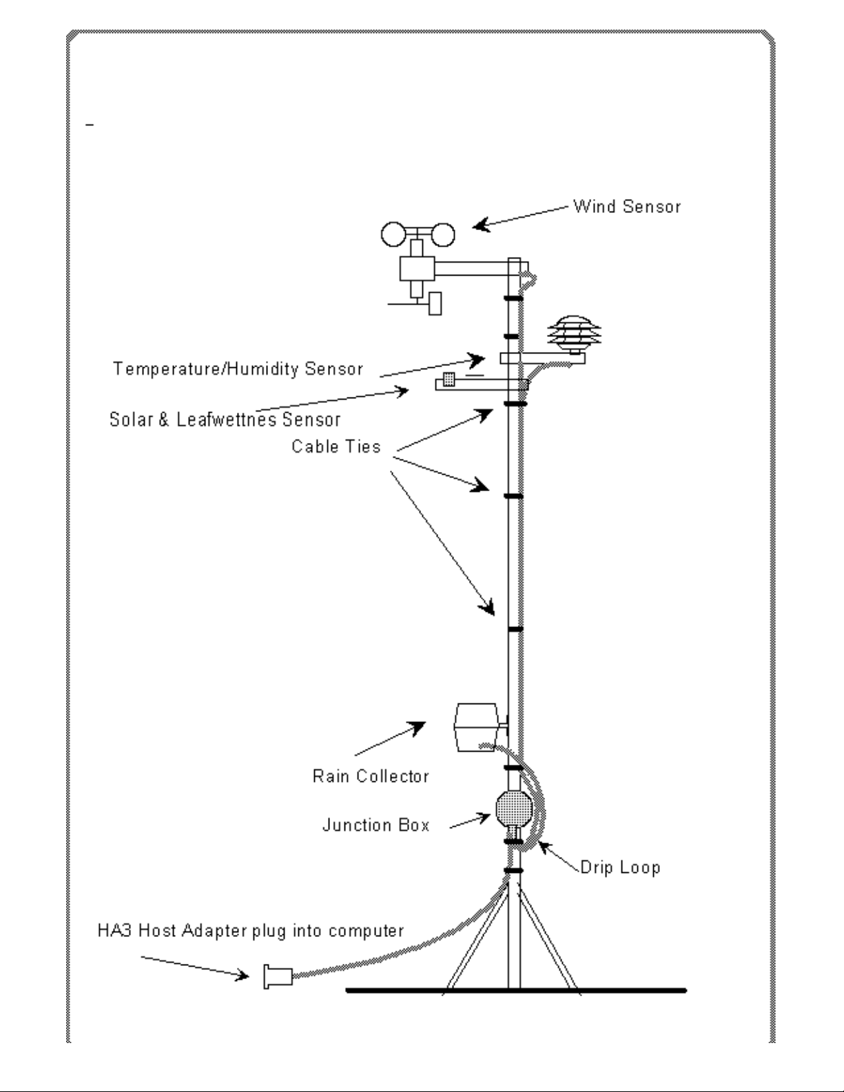
The 1-Wire Weather Station uses multiple sensors to gather weather data. The wind direction and
speed sensor, the temperature/humidity pagoda, the solar radiation/leafwettnes sensor, lightning
sensor and the rain collector are designed to mount to a television type mast (not provided). The
barometric pressure sensor is designed to be inside; plugged into the host adapter. Also plugged
into the host adapter will be with the red intermediate cable that goes to the roof sensors. (Note: the
pressure sensor must be plugged into the host adapter with the TWI dropping adapter in line or the
pressure sensor will not work.)
1-Wire Weather Station
Texas Weather Instruments, Inc. 1-Wire Weather Station
Page 2
1-Wire Weather Station
Texas Weather Instruments, Inc. 1-Wire Weather Station
Page 3

C A U T I O N !! :BE EXTREMELY CAREFUL NOT TO TOUCH ANY HIGH POWER LINES
DURING INSTALLATION OF THE VARIOUS SENSORS!!!
The wind direction and speed sensor is normally mounted on television type antenna masts. For
best results the wind · ·
sensor should be mounted twenty feet above the roof of the building. The higher the installation, the
more accurate the readings. The wind direction sensor is calibrated at the factory and should be
installed with the wind sensor arm pointed to the North. If you are unable to point the wind sensor
arm to the North you can change the wind direction offset in the OneSix server INI file. Plug the
wind sensor RJ11 connector into the mast mounted junction box (if present).
The TWI Lightning Sensor must be mounted at the top of a grounded mast. The taller the mast and
the better the earth grounding the further away lightning can be detected. A detection range of over
200 miles can be achieved depending on the installation.
Mount the Lighting Sensor one inch below and 180 degrees away from the wind sensor (refer to
figure A) in order to gain the maximum distance between the two sensors. The top of the Lightning
sensor must not be below any part of the grounded mast, doing so will shield the sensor from
detecting lightning from that direction
The outside temperature/humidity pagoda should be mounted about two feet under the wind sensor.
Again we suggest a twenty-foot mast for commercial installations to overcome the artificially high
readings generated by a hot roof. Plug the temperature/humidity pagoda cable into RJ11 connector
1-Wire Weather Station
in the junction box.
Texas Weather Instruments, Inc. 1-Wire Weather Station
Page 4

The solar/leafwettness sensor must be pointed South and must be free of shadows created by the
other sensors (near the top of the mast is normally the best). Take care that the sensor is perfectly
level. Run the solar sensor cable to the junction box and plug it in to RJ11 connector.
The rain collector is normally mounted on the mast. It should be mounted as low as possible to
reduce windage and to limit movement of the mast, which can cause false readings. The collector
should be mounted in a manner that allows rain to enter the collector unencumbered by surrounding
obstacles. Use a bubble level to make sure that the collector is perfectly level with the ground.
Failure to level the collector will cause inaccurate rainfall readings. The rain collector has one cable
that must be connected to the junction box.
Mount the junction box under the rain collector using the hose clamps that are installed on the box
(see figure 1). Remove the front cover of the junction box, inserting the connectors from the sensors
and intemediated cable through he hole in the bottom of the junction box and then out of the front of
the box. Plug all the sensor connectors in the junction box being careful not to plug the sensor
cables into the larger red color coded RJ-45 intermediate connectors
The intermediate cable (red) should be plugged in to one of the junction box RJ-45 intermediate
connectors (color coded red), then run into the building where the PC is located. Pull the excess
cable out of the j-box. Carefully seal the bottom hole in the box from the inside by using the
plumber’s putty provided to keep bugs out. Be sure and replace the rubber gasket on the junction
box so that it can remain watertight. If you do not properly put the j-box cover and seal on, the j-box
will leak water and the system will fail. It is a good idea to avoid running the intermediate cable close
to noisy devices such as florescent lights and electric motors. Plug the red intermediate cable RJ-45
connector into the host adapter (HA3 or HA4) and then attach the host adapter to serial port on the
PC. If you have a barometric pressure sensor, plug it also in to the host adapter making sure that
the TWI dropping adapter is in line. Your hardware is now installed, go to software installation.
SOFTWARE INSTALLATION
We strongly suggest that all the 1-Wire Weather Station Sensors, intermediate cable,
junction box and host adapter be connected to your PC, and that your software be installed
on your computer and tested prior to the installation of your sensors on the roof, so that you
may become familiar with the operation of this equipment.
OneSix Server
Find the diskette that is labeled OneSix Server. The OneSix Server is also available via the internet
at www.pointsix.com. Plug all of your hardware in to your computer (through the J-box if supplied)
then install the OneSix server software. The default folder for the OneSix server is c:\onesix (if you
put OneSix server into any other folder, Weather View will not be able to find the server). Click onto
the OneSix server icon and load. OneSix Server will search the 1-Wire Microlan for sensors and
then write to the Onesix.ini file recording your configuration.
To make a DDE link into another program such as Word 97, click on the OneSix DDE Server
button. Then click on DDE Variables in the OneSix Server. Highlight the sensor description that you
1-Wire Weather Station
Texas Weather Instruments, Inc. 1-Wire Weather Station
Page 5

desire and click copy link. Switch to Windows 97, go to edit, then paste special and click on to paste
link. Your data for that sensor should now be in your Word document.
For more information on the OneSix server go to the OneSix manual. Assuming that the OneSix
Server has been installed on your hard drive, use Windows Explorer to go to the onesix folder and
click on to Onesix32.pdf or click on the OneSix Server icon in your startup menu.
Weather View 32
Make sure that you have already installed the OneSix server program on you computer, then using
the Weather View 32 CD, install Weather View 32. The OneSix server is a program that runs the
1-Wire Microlan and provides data to the Weather View 32 program via a DDE link. Weather View
will automatically load the OneSix Server software.
The only sensor that must be calibrated is barometric pressure. Obtain the correct local pressure
from a reliable source such as a weather radio or TV Station, go into the setup menu, then weather
station properties and change the offset. For more information on Weather View 32, refer to the
Weather View 32 manual.
CONNECTOR PINOUTS
Screw Connector PIN SIGNAL/SYMBOL DESCRIPTION
1 PGND "G" Power Ground
2
1–Wire Ground
Pin "C"
Microlan™
Ground
3
1–Wire Input/Output
Pin "S"
Microlan™
network I/O
4 PWR "+"
Power + (unreg)
5-16 V DC
RJ-11 PINOUT
RJ11 PIN SIGNAL DESCRIPTION
1
No connection No connection
2
PGND Power Ground
3
1–Wire Input/Output Pin
Microlan™
Network I/O
4
1–Wire Ground Pin
Microlan™
Ground
5
No connection No connection
6
PWR
Power + (unreg)
5-16 V DC
1-Wire Weather Station
Texas Weather Instruments, Inc. 1-Wire Weather Station
Page 6

FCC RADIO FREQUENCY INTERFERENCE STATEMENT
NOTE: This equipment has been tested and found to comply with the limits for a Class B digital
device, pursuant to Part 15, Subpart B, of the FCC Rules. This equipment generates, uses, and can
radiate radio frequency energy. If not installed and used in accordance with the instructions, may
cause interference to radio communications.
The limits are designed to provide reasonable protection against such interference in a residential
situation. However, there is no guarantee that interference will not occur in a particular installation. If
this equipment does cause interference to radio or television reception, which can be determined by
turning the equipment off and on, the user is encouraged to try and correct the interference by one
or more of the following measures:
· Reorient or relocate the receiving antenna of the affected radio or television
· Increase the separation between the equipment and the affected receiver.
· Connect the equipment and the affected receiver to power outlets on separate circuits.
· Consult the dealer or an experienced radio/TV technician for help.
MODIFICATIONS
Changes or modifications not expressly approved by Texas Weather Instruments, Inc. could void
the user's authority to operate the equipment.
TOP
1-Wire Weather Station
Texas Weather Instruments, Inc. 1-Wire Weather Station
 Loading...